EP2114673B1 - Security document - Google Patents
Security document Download PDFInfo
- Publication number
- EP2114673B1 EP2114673B1 EP08707586A EP08707586A EP2114673B1 EP 2114673 B1 EP2114673 B1 EP 2114673B1 EP 08707586 A EP08707586 A EP 08707586A EP 08707586 A EP08707586 A EP 08707586A EP 2114673 B1 EP2114673 B1 EP 2114673B1
- Authority
- EP
- European Patent Office
- Prior art keywords
- layer
- watermark
- security document
- security
- carrier substrate
- Prior art date
- Legal status (The legal status is an assumption and is not a legal conclusion. Google has not performed a legal analysis and makes no representation as to the accuracy of the status listed.)
- Revoked
Links
- 239000000758 substrate Substances 0.000 claims abstract description 93
- 229920003023 plastic Polymers 0.000 claims abstract description 11
- 239000004033 plastic Substances 0.000 claims abstract description 10
- 230000000694 effects Effects 0.000 claims description 36
- 230000001419 dependent effect Effects 0.000 claims description 10
- 230000000737 periodic effect Effects 0.000 claims description 2
- 239000000463 material Substances 0.000 abstract description 24
- 230000003287 optical effect Effects 0.000 abstract description 15
- 239000010410 layer Substances 0.000 description 337
- 230000005540 biological transmission Effects 0.000 description 27
- 229910052751 metal Inorganic materials 0.000 description 22
- 239000002184 metal Substances 0.000 description 22
- 229910052782 aluminium Inorganic materials 0.000 description 18
- XAGFODPZIPBFFR-UHFFFAOYSA-N aluminium Chemical compound [Al] XAGFODPZIPBFFR-UHFFFAOYSA-N 0.000 description 18
- 238000012546 transfer Methods 0.000 description 14
- 239000004922 lacquer Substances 0.000 description 11
- 239000012790 adhesive layer Substances 0.000 description 9
- 125000006850 spacer group Chemical group 0.000 description 9
- 238000005286 illumination Methods 0.000 description 7
- BQCADISMDOOEFD-UHFFFAOYSA-N Silver Chemical compound [Ag] BQCADISMDOOEFD-UHFFFAOYSA-N 0.000 description 6
- 238000013461 design Methods 0.000 description 6
- 229920002120 photoresistant polymer Polymers 0.000 description 6
- 229910052709 silver Inorganic materials 0.000 description 6
- 239000004332 silver Substances 0.000 description 6
- 230000015572 biosynthetic process Effects 0.000 description 5
- 239000003086 colorant Substances 0.000 description 5
- 238000010030 laminating Methods 0.000 description 5
- 238000002834 transmittance Methods 0.000 description 5
- 238000010586 diagram Methods 0.000 description 4
- 238000004519 manufacturing process Methods 0.000 description 4
- 239000011248 coating agent Substances 0.000 description 3
- 238000000576 coating method Methods 0.000 description 3
- PCHJSUWPFVWCPO-UHFFFAOYSA-N gold Chemical compound [Au] PCHJSUWPFVWCPO-UHFFFAOYSA-N 0.000 description 3
- 229910052737 gold Inorganic materials 0.000 description 3
- 239000010931 gold Substances 0.000 description 3
- 239000004973 liquid crystal related substance Substances 0.000 description 3
- 238000000034 method Methods 0.000 description 3
- 230000005855 radiation Effects 0.000 description 3
- 230000010076 replication Effects 0.000 description 3
- VYZAMTAEIAYCRO-UHFFFAOYSA-N Chromium Chemical compound [Cr] VYZAMTAEIAYCRO-UHFFFAOYSA-N 0.000 description 2
- RYGMFSIKBFXOCR-UHFFFAOYSA-N Copper Chemical compound [Cu] RYGMFSIKBFXOCR-UHFFFAOYSA-N 0.000 description 2
- 238000010521 absorption reaction Methods 0.000 description 2
- 238000004026 adhesive bonding Methods 0.000 description 2
- 229910052804 chromium Inorganic materials 0.000 description 2
- 239000011651 chromium Substances 0.000 description 2
- 229910052802 copper Inorganic materials 0.000 description 2
- 239000010949 copper Substances 0.000 description 2
- 230000007423 decrease Effects 0.000 description 2
- 238000001746 injection moulding Methods 0.000 description 2
- 230000010354 integration Effects 0.000 description 2
- 239000000049 pigment Substances 0.000 description 2
- 239000011241 protective layer Substances 0.000 description 2
- 238000004088 simulation Methods 0.000 description 2
- 239000000126 substance Substances 0.000 description 2
- 230000000007 visual effect Effects 0.000 description 2
- 239000004831 Hot glue Substances 0.000 description 1
- 241000283973 Oryctolagus cuniculus Species 0.000 description 1
- 241000220317 Rosa Species 0.000 description 1
- RTAQQCXQSZGOHL-UHFFFAOYSA-N Titanium Chemical compound [Ti] RTAQQCXQSZGOHL-UHFFFAOYSA-N 0.000 description 1
- 238000003848 UV Light-Curing Methods 0.000 description 1
- 239000000956 alloy Substances 0.000 description 1
- 229910045601 alloy Inorganic materials 0.000 description 1
- 238000000149 argon plasma sintering Methods 0.000 description 1
- 239000005387 chalcogenide glass Substances 0.000 description 1
- 239000002131 composite material Substances 0.000 description 1
- 239000004020 conductor Substances 0.000 description 1
- 239000000470 constituent Substances 0.000 description 1
- 238000004049 embossing Methods 0.000 description 1
- 238000005530 etching Methods 0.000 description 1
- 239000011888 foil Substances 0.000 description 1
- 239000011521 glass Substances 0.000 description 1
- 230000001771 impaired effect Effects 0.000 description 1
- 238000003780 insertion Methods 0.000 description 1
- 230000037431 insertion Effects 0.000 description 1
- 238000003475 lamination Methods 0.000 description 1
- 238000000608 laser ablation Methods 0.000 description 1
- 230000031700 light absorption Effects 0.000 description 1
- 239000000696 magnetic material Substances 0.000 description 1
- 239000011159 matrix material Substances 0.000 description 1
- 238000012634 optical imaging Methods 0.000 description 1
- 230000010363 phase shift Effects 0.000 description 1
- 239000002985 plastic film Substances 0.000 description 1
- 229920006255 plastic film Polymers 0.000 description 1
- 229910052714 tellurium Inorganic materials 0.000 description 1
- PORWMNRCUJJQNO-UHFFFAOYSA-N tellurium atom Chemical compound [Te] PORWMNRCUJJQNO-UHFFFAOYSA-N 0.000 description 1
- 238000012360 testing method Methods 0.000 description 1
- 229920001169 thermoplastic Polymers 0.000 description 1
- 239000004416 thermosoftening plastic Substances 0.000 description 1
- 229910052719 titanium Inorganic materials 0.000 description 1
- 239000010936 titanium Substances 0.000 description 1
- 238000012795 verification Methods 0.000 description 1
- 238000005406 washing Methods 0.000 description 1
Images


Classifications
-
- B—PERFORMING OPERATIONS; TRANSPORTING
- B42—BOOKBINDING; ALBUMS; FILES; SPECIAL PRINTED MATTER
- B42D—BOOKS; BOOK COVERS; LOOSE LEAVES; PRINTED MATTER CHARACTERISED BY IDENTIFICATION OR SECURITY FEATURES; PRINTED MATTER OF SPECIAL FORMAT OR STYLE NOT OTHERWISE PROVIDED FOR; DEVICES FOR USE THEREWITH AND NOT OTHERWISE PROVIDED FOR; MOVABLE-STRIP WRITING OR READING APPARATUS
- B42D25/00—Information-bearing cards or sheet-like structures characterised by identification or security features; Manufacture thereof
- B42D25/30—Identification or security features, e.g. for preventing forgery
- B42D25/333—Watermarks
-
- B—PERFORMING OPERATIONS; TRANSPORTING
- B42—BOOKBINDING; ALBUMS; FILES; SPECIAL PRINTED MATTER
- B42D—BOOKS; BOOK COVERS; LOOSE LEAVES; PRINTED MATTER CHARACTERISED BY IDENTIFICATION OR SECURITY FEATURES; PRINTED MATTER OF SPECIAL FORMAT OR STYLE NOT OTHERWISE PROVIDED FOR; DEVICES FOR USE THEREWITH AND NOT OTHERWISE PROVIDED FOR; MOVABLE-STRIP WRITING OR READING APPARATUS
- B42D25/00—Information-bearing cards or sheet-like structures characterised by identification or security features; Manufacture thereof
- B42D25/20—Information-bearing cards or sheet-like structures characterised by identification or security features; Manufacture thereof characterised by a particular use or purpose
- B42D25/23—Identity cards
-
- B—PERFORMING OPERATIONS; TRANSPORTING
- B42—BOOKBINDING; ALBUMS; FILES; SPECIAL PRINTED MATTER
- B42D—BOOKS; BOOK COVERS; LOOSE LEAVES; PRINTED MATTER CHARACTERISED BY IDENTIFICATION OR SECURITY FEATURES; PRINTED MATTER OF SPECIAL FORMAT OR STYLE NOT OTHERWISE PROVIDED FOR; DEVICES FOR USE THEREWITH AND NOT OTHERWISE PROVIDED FOR; MOVABLE-STRIP WRITING OR READING APPARATUS
- B42D25/00—Information-bearing cards or sheet-like structures characterised by identification or security features; Manufacture thereof
- B42D25/20—Information-bearing cards or sheet-like structures characterised by identification or security features; Manufacture thereof characterised by a particular use or purpose
- B42D25/24—Passports
-
- B—PERFORMING OPERATIONS; TRANSPORTING
- B42—BOOKBINDING; ALBUMS; FILES; SPECIAL PRINTED MATTER
- B42D—BOOKS; BOOK COVERS; LOOSE LEAVES; PRINTED MATTER CHARACTERISED BY IDENTIFICATION OR SECURITY FEATURES; PRINTED MATTER OF SPECIAL FORMAT OR STYLE NOT OTHERWISE PROVIDED FOR; DEVICES FOR USE THEREWITH AND NOT OTHERWISE PROVIDED FOR; MOVABLE-STRIP WRITING OR READING APPARATUS
- B42D25/00—Information-bearing cards or sheet-like structures characterised by identification or security features; Manufacture thereof
- B42D25/20—Information-bearing cards or sheet-like structures characterised by identification or security features; Manufacture thereof characterised by a particular use or purpose
- B42D25/29—Securities; Bank notes
-
- D—TEXTILES; PAPER
- D21—PAPER-MAKING; PRODUCTION OF CELLULOSE
- D21H—PULP COMPOSITIONS; PREPARATION THEREOF NOT COVERED BY SUBCLASSES D21C OR D21D; IMPREGNATING OR COATING OF PAPER; TREATMENT OF FINISHED PAPER NOT COVERED BY CLASS B31 OR SUBCLASS D21G; PAPER NOT OTHERWISE PROVIDED FOR
- D21H21/00—Non-fibrous material added to the pulp, characterised by its function, form or properties; Paper-impregnating or coating material, characterised by its function, form or properties
- D21H21/14—Non-fibrous material added to the pulp, characterised by its function, form or properties; Paper-impregnating or coating material, characterised by its function, form or properties characterised by function or properties in or on the paper
- D21H21/40—Agents facilitating proof of genuineness or preventing fraudulent alteration, e.g. for security paper
- D21H21/44—Latent security elements, i.e. detectable or becoming apparent only by use of special verification or tampering devices or methods
-
- B42D2033/06—
-
- B42D2035/20—
Definitions
- the invention relates to a security document, comprising a translucent carrier substrate, in particular made of paper and / or plastic, and at least one embedded on the carrier substrate or embedded in the carrier substrate security element, which seen from at least a first side of the security document in transmitted light at least a first image and a presence of at least one first watermark in the carrier substrate is simulated, wherein the security element at least partially at least one, the at least one first watermark simulating layer which changes the visually perceptible translucency of the carrier substrate locally.
- a security foil is applied to a security or stored in it as a security element.
- the security film consists of a translucent carrier film and a metallic coating applied thereon, which has metal-free regions, which are clearly visible especially in transmitted light.
- the metallic coating is divided into individual halftone dots which produce a halftone image. If the security film is embedded between two layers of security paper, the metallic coating simulates the presence of a watermark in the security paper, which is clearly visible in transmitted light.
- a conventional watermark in paper is created by locally changing the thickness of the paper as it is made, thus resulting in transmission differences in the paper.
- transmitted light is for a viewer from both sides of the paper a continuous grayscale image, the so-called watermark, recognizable.
- a simulation of a watermark by a security element has the advantage that the complicated production process, as required in conventional watermarking on paper substrates, can be avoided. Furthermore, by means of a simulated watermark and a translucent plastic substrate can be easily equipped with a watermark effect. Only embedding or applying a security element formed independently of the translucent carrier substrate of the security document into or onto the translucent carrier substrate, whether made of paper, plastic, or Teslin® , or laminates of these materials, is required. Depending on the configuration of the security element, a wide variety of watermarks can be simulated in one and the same carrier substrate.
- the at least one, the first watermark simulating layer contains one or more substances (such as luminescent, thermochromic, photochromic substances and the like), with such radiation can be stimulated.
- paper and / or plastic and / or Teslin® or a composite of such materials has proven to be a translucent carrier substrate.
- translucent means that the carrier substrate is translucent, but not transparent or transparent. In the carrier substrate, a volume scattering occurs and the light passing through is scattered more or less strongly depending on the material selection and material thickness.
- the at least one layer simulating the first watermark is preferably by at least one metal layer and / or at least one dielectric layer, in particular having a high refractive index and / or at least one chalcogenide glass layer and / or a pigmented layer, in particular a pigmented ink layer or ink, and / or or a liquid crystal layer is formed.
- a combination of at least one metal layer and at least one pigmented layer has proved particularly useful.
- the security document is viewed in reflected light, then it is assumed here that it is viewed by a human eye under normal conditions, ie in daylight or artificial light, with the light from the side of the observer striking the security document.
- the security element is viewed in transmitted light, it is assumed to be under normal conditions by the human eye, the light from the back of the security document, ie the side of the security document facing away from the viewer, impinging on it.
- the layer simulating at least one first watermark has regions with different transmissivity.
- the security element is applied on the second side of the security document or is embedded in the translucent carrier substrate such that the security element is in a plane parallel to the first side and the second side, and a portion of the support substrate located on the second side between the at least one watermark simulating layer and a viewer is at least partially recessed, areas visible from the second side being the first one Watermark simulating layer can be seen visually in the reflected light as a closed, opaque layer areas, but at least the visible areas of the first watermark simulating layer in the transmitted light are different transmissive.
- the observer recognizes the first watermark in the case of a security document according to case a) as usual when viewing the first page in transmitted light.
- the observer sees in the incident light the security element applied to the carrier substrate and the at least one layer simulating the first watermark, the shape of which, however, does not coincide with the shape of the first watermark contrary to expectations.
- the first watermark is recognizable from the second side as well - possibly reversed from one side to the other. This effect is achieved by forming the at least one layer which simulates at least one first watermark with regions of different transmissivity, which are visually distinguishable from one another only in transmitted light.
- the security element is in a plane parallel to the first side and the second side of the security document, and a portion of the carrier substrate located on the second side between the at least one opaque layer and one Viewer is located, is recessed, realized by the carrier substrate is formed of at least two layers and the at least one security element is disposed between these layers.
- the carrier substrate is formed of at least two layers and the at least one security element is disposed between these layers.
- a window opening is, as well as below in the text, understood not only an opening, but also a transparent or transparent area, for example, made of transparent plastic.
- a window opening could also be introduced into both layers and the at least one security element be brought into coincidence with both window openings. Subsequently, the security element is covered on the first side with at least one translucent ink layer, so that the layer simulating the at least one first watermark can only be seen from the second side.
- At least one translucent ink layer can also already be a component of the security element, so that a job after the embedding of the security element in the carrier substrate can be dispensed with.
- a translucent ink layer may further be formed by a translucent adhesive layer which is used to embed the security element between the layers of the carrier substrate for bonding to a layer.
- the at least one layer simulating the watermark shows a different surface area as seen in transmitted light, as seen in transmitted light.
- the layer simulating the first watermark is applied to the second side of the security document and is partially covered by at least one translucent ink layer arranged on the second side, or embedded in the translucent carrier substrate, in that the security element is located in a plane parallel to the first side and the second side, and a region of the carrier substrate located on the second side between the at least one, the first Watermark simulating layer and a viewer located, either partially recessed or completely recessed and is partially covered by at least one arranged on the second side of the translucent color layer, wherein the visible from the second side of the first watermark simulating layer in incident light visually as a partially formed opaque layer areas are to be recognized, which show a security information, and shows in the transmitted light from the second side, the at least one first watermark, which differs from the security information.
- a viewer recognizes in a security document according to case a) also as usual when viewing the first page in transmitted light, a first watermark.
- the observer sees the security element applied to the carrier substrate or partially formed opaque regions of the first watermark simulating layer in the reflected light, which show security information, however, the shape of which does not coincide with the shape of the first watermark contrary to expectations.
- the watermark can now be seen from the second page as well - now possibly reversed.
- this effect is achieved by the fact that, visible to the viewer in the reflected light, only parts of the layer which is formed over the whole area or in regions and which simulate the first watermark are arranged so as to be immediately visible.
- the layer simulating the first watermark can also be equipped with regions of different transmissivity, which are visually distinguishable from one another only in transmitted light.
- the effect can also be achieved by the at least one opaque layer-which is readily visible to the human eye-only partially formed and completely visible and further having regions of different transmissivity, which are visually distinguishable from each other only in transmitted light.
- an area of the layer simulating the first watermark in transmitted light is perceived by the human observer to be opaque if the transmission for visible light is less than 5%, in particular less than 1%.
- a translucent a viewer perceives in transmitted light areas with a transmission for visible light of greater than 10%, in particular greater than 20%. In reflected light can be For a viewer, however, even in the areas that are translucent in transmitted light, the impression of an opaque layer area results.
- a metallic layer is used as the layer simulating the first watermark, then the areas which are opaque and translucent in transmitted light reflect a maximum of a factor of 10 when viewed in reflected light. A reflection that is different by a factor of 10 is easily recognizable to the human eye, while a difference in reflection of up to approximately 20% is barely perceptible.
- the human eye can not resolve the differences in reflected light and perceives a uniformly opaque surface.
- the security element is embedded in the translucent carrier substrate and is located in a plane parallel to the first side and the second side, wherein a region of the carrier substrate which is located on the second Side between the at least one, the first watermark simulating layer and a viewer is located, at least partially recessed, realized by the carrier substrate is formed at least from two layers and the at least one security element between these layers is arranged.
- one of them is provided with a window opening and the window opening is placed over the security element in such a way that the at least one layer simulating the first watermark is only partially visible.
- the first watermark simulating layer could also be completely visible and these are then partially covered with the translucent color layer.
- a window opening to be introduced in both layers and for the at least one security element to be brought into overlap with both window openings.
- the security element on the first page is partially or completely covered with a translucent color layer and partially covered on the second side with the translucent color layer, so that the, the first watermark simulating layer on the second side in incident light only partially visible.
- the at least one, the first watermark simulating layer is not or only partially visible. If the at least one layer simulating the first watermark is also partly visible in incident light on the first side, then it is preferred if different regions of the at least one layer simulating the first watermark are visible on the first side and the second side in incident light ,
- At least one translucent ink layer may also already be a constituent of the security element or translucent adhesive layers may be used for embedding, so that an application after embedding the security element in the carrier substrate may be unnecessary.
- an optical concealment of the presence of window openings in the carrier substrate integration of translucent color layers into the security element in combination with an additional application of translucent color layers after embedding the security element or using translucent adhesive layers for embedding can be advantageous.
- the at least one first watermark simulating layer on the first side and a second side of the security document opposite the first side is at least partially covered by at least one translucent layer at least one translucent layer on the first side and the at least one translucent layer on the second side scatter light to different degrees.
- the security element has been arranged on the second side and the watermark simulating layer is covered by at least one translucent color layer arranged on the second side, or the security element is embedded in the translucent carrier substrate the security element is in a plane parallel to the first side and the second side, but at a unequal distance from the first side and the second side, or the security element embedded in the translucent carrier substrate and the watermark simulating layer through at least one, on the first Side and / or the second side arranged translucent color layer is covered, wherein the first watermark simulating layer seen from the second side in transmitted light at least one second image that simulates the presence of at least one, different from the first watermark second watermark in the carrier substrate.
- a viewer also recognizes, as usual, when viewing the first page in transmitted light, a first watermark.
- the observer does not or only partially see the at least one layer simulating the first watermark in incident light.
- the observer on the second page has a second watermark different from the first watermark.
- This effect is achieved by forming the security document in such a way that the light passing through is scattered to different degrees between the first watermark simulating layer and the first side and between the first watermark simulating layer and the second side. This causes, for example, filigree openings in the first watermark simulating layer to be seen from the second side in transmitted light, but not from the first side.
- the carrier substrate is formed from at least two layers of different material.
- the embedding of the security element and the arrangement and configuration of translucent layers can furthermore be carried out analogously to the case a) already described above.
- An imitation of the security document according to the invention in accordance with one of the cases b) or b) in combination with a) is difficult because an exact formation of different layer thicknesses and / or openings or transparent areas depending on the material of the at least one layer simulating the first watermark must be performed on the at least one, the first watermark simulating layer or the scattering behavior of layers in coordination with the design of the first watermark simulating layer must be set.
- the at least one layer simulating the first watermark has regions with transmissivity dependent on the viewing angle.
- the at least one first watermark in transmitted light when tilting the security document shows a kinematic effect and / or a three-dimensional effect and / or a color-changing effect on at least one side of the security document.
- a viewer also recognizes, as usual, when viewing the first page in transmitted light, a first watermark. On the second page, the viewer also sees the watermark.
- a kinematic effect and / or a three-dimensional effect and / or a color change effect comes to light.
- the first kinematic watermark appears to the viewer as if it were moving, such as when an illustrated person were making a movement.
- the first watermark with a three-dimensional effect appears to the viewer as if a three-dimensional object were embedded in the carrier substrate.
- the first watermark with color change effect shows the viewer different colors or colors at different viewing angles.
- the security element is formed with a viewing angle-dependent local transmissivity which essentially results from the configuration of the at least one layer simulating the first watermark, if appropriate also by the presence of diffractive structures and Spacer layers in the security element, conditional.
- a combination of cases a) to c) has proven itself by the security document, or even the security element, at least a first Having area, which is designed according to case b), and further comprises at least a second region, which is configured according to at least one of the cases a) and c).
- the achievable effects can thus be combined in a particularly effective manner.
- the different effects can be present on a single security element or distributed over several security elements.
- a plurality of identically and / or differently formed security elements can be used on a security document.
- at least one first security element can be arranged on the second side and a second security element can be embedded in the carrier substrate.
- security elements can be arranged on both sides of the security document, which simulate the presence of a watermark on the respective opposite side in transmitted light.
- At least one translucent ink layer it has proven to be useful if it does not differ in color or differs only slightly from, optionally printed in color, adjacent areas of the carrier substrate. As a result, the presence of the security element in these areas is visually hidden or made unrecognizable to the viewer.
- the at least one layer simulating the first watermark has transparent regions and / or openings whose dimensions, at least in one direction, are below the resolution limit of the human eye, that is to say smaller than approximately 0.3 mm.
- openings whose dimensions, at least in one direction are in the range from 1 to 250 ⁇ m, in particular in the range from 2 to 100 ⁇ m, and in particular in the range from 5 to 80 ⁇ m.
- Such transparent areas or openings are invisible to the human eye in incident light, but are easily recognizable in transmitted light due to the increased transmission of light.
- the at least one layer simulating the first watermark has transparent regions and / or openings, the mean surface density of the transparent regions or openings in the opaque layer being ⁇ 10%.
- Such transparent areas or openings are also invisible to the human eye in incident light, but are easily recognizable in transmitted light due to the increased transmission of light.
- the at least one layer simulating the first watermark has regions with different layer thicknesses.
- the areas with different layer thicknesses may appear continuously opaque to the human eye in incident light, however, areas with lower layer thickness in transmitted light due to the increased transmission of light easily distinguishable from areas with higher layer thickness.
- the material used to form the at least one first watermark simulating layer may be in such a small layer thickness that it is not substantially noticeable Has an influence on the transmission properties of the security document.
- the structuring of the at least one layer simulating the first watermark, or the formation of openings or transparent areas, can be carried out according to a method DE 102004042136 A1 will be realized.
- the layer thickness of the layer is adjusted by uniformly applying the material for forming the layer to a surface provided with diffractive surface structures, a locally different effective layer thickness being established depending on the depth-to-width ratio of the surface structures.
- the at least one layer simulating the first watermark may have a continuously changing layer thickness at least in regions in the regions which appear opaque in the incident light. Alternatively or in combination with this, the at least one layer simulating the first watermark in the regions which appear opaque in the incident light can at least in some areas become one have gradually changing layer thickness.
- the formation of the different layer thickness produces a different transmissivity or optical density seen in transmitted light and can also according to a method according to DE 102004042136 A1 be realized.
- the at least one layer simulating the first watermark has openings such that this layer is structured in the form of a fine dot or line grid with a screen width of less than 300 ⁇ m. It is particularly preferred if the layer is structured in the form of an aperiodic point or line grid.
- points or lines are understood here not only circular pixels, but also other geometric shapes such as triangular, rectangular, elliptical, etc. pixels. Also, pixels in the form of symbols, pictorial representations, alphanumeric characters or strings are possible.
- the points or lines are arranged either in a uniform grid spacing or a locally or continuously changing grid spacing. Alternatively or in combination, the areal extent of the points or lines may vary.
- a substructuring is understood as meaning, for example, a phase shift of a subset of pixels or lines in relation to the rest of the screen. Further possibilities for a substructuring consist in a local change of a curvature of lines, a local change in the orientation of the pixels or lines, a local change of the dot or line spacing, a local change in shape of pixels or lines, an education in the form of different characters or picture elements etc.
- a single line can be sub-structured by the line being composed of a sequence of letters which, at least in sections, has a specific, readable information content.
- Substructures of this kind can only be read out with auxiliary means, for example by means of a magnifying glass or by means of superposition with a further dot or line grid in the manner of a verification plate.
- the security element has at least two layers which are arranged overlapping one another at least in regions and which simulate the at least one first watermark.
- at least one transparent spacer layer is preferably arranged between the at least two layers simulating the at least one first watermark.
- the first and the second layer preferably have a multiplicity of subregions differing in their transmission and reflection properties. These different subregions are preferably arranged in the respective layer according to a regular, periodic grid. The grid spacings are preferably below the resolution of the human eye. Depending on the angle of view, different partial areas of the first and second layer in the beam path of the transmitted or reflected light overlap, so that, depending on the viewing angle, a different optical impression in reflected light and in transmitted light is displayed for the viewer.
- first and second layers can also have diffractive structures in partial regions that act in transmission or in reflection.
- diffractive structures in partial regions that act in transmission or in reflection.
- the angular resolution of the viewing-angle-dependent effect can be further refined by a different thickness of the transparent spacer layer.
- the security element has an optically variable effect, which is visible when viewed in incident light.
- the security element has in particular an optically variable material, in particular an optically variable pigment, a liquid crystal material, a luminescent material or a thermochromic material, and / or a diffractive or refractive structure, in particular a hologram, a Kinegram ®, a stochastic matt structure, an asymmetric Matt structure, a macrostructure, a light-absorbing structure or a microlens structure, on.
- an optically variable material in particular an optically variable pigment, a liquid crystal material, a luminescent material or a thermochromic material, and / or a diffractive or refractive structure, in particular a hologram, a Kinegram ®, a stochastic matt structure, an asymmetric Matt structure, a macrostructure, a light-absorbing structure or a microlens structure, on.
- the security element has at least one transparent layer adjoining the at least one layer simulating at least one first watermark, in which, in particular, a diffractive structure is molded.
- the transparent layer is formed as a lacquer layer, in particular as a thermoplastic or UV-cured lacquer layer.
- the transparent layer can also be formed without a diffractive structure and serve as a protective layer for the layer simulating at least one first watermark, in order at least partially to cover a layer simulating the at least one watermark on the security document and subjecting it to mechanical stress Minimize layer.
- the transparent layer can serve as a spacer layer between the layers which simulate at least one first watermark or give this layer or the watermark in transmitted light, if it is colored, a colored appearance.
- the security element has at least two layers that simulate at least one first watermark, then it is preferable for these to be present at least one translucent ink layer and / or a transparent layer, optionally containing diffractive structures arranged.
- a translucent ink layer is preferably formed by a pigmented lake layer. Both pastel colors and pure colors can be used.
- color layers are formed by colored photoresist layers, which are formed in regions in the register for the at least one first watermark simulating layer.
- the layer simulating the at least one first watermark can serve as the exposure mask in order to structure the photoresist layers in the register.
- the transparent layer has a multiplicity of microlenses, wherein a layer thickness of the at least one transparent layer corresponds at least approximately to the focal length of the microlenses.
- the security element has one or more transparent first layers and a second layer having a plurality of micro-patterns of one or more opaque first portions and one or more transparent second portions that one of the first layers on its second layer facing away from the surface having a surface profile forming a plurality of first microlenses, and that the thickness of said first layer or said first layer and between said first layer and the second layer disposed one or more further first layers corresponds approximately to the focal length of the first microlens.
- the security element therefore has first subregions in which at least the second layer is opaque; and it has second subregions in which all layers of the security element are transparent.
- the security element is transparent throughout, ie, the layers of the security element are designed to be transparent in the area of the second partial areas.
- Such a security element forms when viewed from the front and from the back very different optical effects, which form a hard to imitate security feature.
- the microlenses formed in one of the first layers form an optical imaging system suitable for enlarging the micropatterns. Through the microlenses is each selected one pixel of the micropattern per microlens. Due to the microlenses, this is very bright, but in principle a shadow mask would also work.
- the micropattern consists of first subregions which appear opaque to the human observer or the human eye, ie opaque (by absorption or reflection of the incident light), and second subareas which appear translucent to the human observer or the human eye.
- the overall impression produced in this way shows transparent image areas that change their position depending on the viewing direction, so that it may seem that a transparent image area floats against an opaque background. Images may appear to appear behind the surface of the security element, or in front of or in the surface thereof, depending on whether the screen pitch of the microlenses is smaller or larger than the screen pitch of the microimages.
- the two screen rulings are exactly the same, but slightly twisted, the interesting effect is that images appear to move from left to right as the security element moves back and forth a bit and images seem to move back and forth when the security element is moved to the left and to the right. It is also possible that images are reversed or rotated, ie the images may be enlarged versions of the micropatterns (magnification> 1) or the images may be reversed or rotated versions of the micropatterns (magnification ⁇ -1).
- the security element when viewed from the back side, the security element appears as an opaque area which, for example, can show information in the manner of a halftone or gray scale image. This apparent contradiction between the two optical impressions is evident both in reflected light and in transmitted light and is very striking and memorable.
- the thickness of the microlens layer may vary between 10% to 20% of the focal length from the nominal value.
- the at least one layer simulating the at least one first watermark is characterized by at least one metal layer and / or at least one pigmented layer, in particular a highly pigmented layer Color lacquer layer is formed.
- the layer simulating the at least one first watermark is preferably opaque to the human eye under normal illumination conditions, ie in daylight and artificial light, at least in reflected light. Seen in transmitted light, however, this layer can be translucent at least in some areas.
- metal layer which appears opaque to the human eye in reflected light.
- visible or transmissive or transparent regions in transmitted light it is important to know and to select the individual influencing parameters when forming the metal layer in its dependencies.
- the existing absorption must be taken into account, by which the sum of transmission and reflection is less than 100%.
- An observer already sees a region of a metal layer in reflected light as fully reflective when 85% of the incident light is reflected, and already perceives an area as transparent when less than 20% of the incident light is reflected, i. more than 80% are allowed through.
- chromium and copper may reflect much less than gold and silver. This may mean that only 50% of the incident light is reflected, the transmittance being less than 1%.
- the transmittance also decreases if necessary, if the angle of incidence of the light differs from the normal angle of incidence, ie the transmittance decreases when the light is not incident vertically.
- a metal layer for example in the region of a surface relief structure, can be designed to be transmissive only in a limited incidence cone of the light. It can therefore be provided that a metal layer appears opaque only in an oblique view in incident light.
- the at least one layer simulating the at least one first watermark is formed from a combination of at least one metal layer and at least one pigmented layer.
- the pigmented layer is also preferably a layer which appears opaque to the human eye under normal illumination conditions, at least in incident light. In transmitted light, however, as well as in the metal layer, translucent areas may be present. If the layer simulating the at least one first watermark is at least partially visible on the security document, then in a combination of metal layer and pigmented layer visible in incident light, colored patterns can be formed in combination with metallic patterns and the layer simulating the at least one first watermark thus be designed especially forgery-proof.
- the carrier substrate is provided with a translucent security imprint.
- Security imprints are usually difficult to imitate due to their design or the materials used.
- a security imprint made of filigree lines or guilloches is usually used on banknotes, whereby visually variable materials can also be used.
- the layer simulating the at least one first watermark shows a halftone image when viewed in reflected light and / or transmitted light.
- the security imprint comprises colored material and / or magnetic material and / or electrically conductive material and / or optically variable material, in particular luminescent material, thermochromic material, interference pigments or liquid crystal material.
- luminescent material of a security imprint can be superimposed with the at least one layer simulating the at least one first watermark, whereby in the transmitted light an intensive illumination of the transparent areas or openings in the at least one, the at least one first Watermark simulating layer can be observed.
- the security element is formed by a laminating film or a transfer layer of a transfer film.
- a laminating film a self-supporting, translucent or transparent carrier film is present, on which the at least one layer simulating the at least one first watermark and, if required, further layers, such as transparent layers, optically variable layers, translucent layers, adhesive layers, etc., are formed ,
- a transfer film usually has a self-supporting carrier film on which there is a transfer layer which comprises at least one layer simulating the at least one first watermark and, if required, further layers such as protective layers, transparent layers, optically variable layers, translucent layers, Adhesive layers, etc., is constructed.
- the individual layers of the transfer layer are usually so thin that they, like the transfer layer, are not self-supporting.
- a laminating film usually has a layer thickness which is at least 50% higher than a transfer layer and is thus suitable for use in a continuous window in the carrier substrate.
- the carrier film of the transfer film is removed after fixing the transfer layer on the carrier substrate of the security document.
- a good detachment behavior of the carrier film is required by the transfer layer, which can optionally be set defined by an arrangement of waxy or silicone-like release layers between the carrier film and the transfer layer.
- the security document according to the invention may be a banknote, a bank card, an ID card, a passport, a passport, a security, a deed or much more.
- Banknotes may be conventional banknotes with a substrate of security paper or banknotes with a substrate in the form of a multilayer laminate of plastic.
- the security element is embedded in or applied to the corresponding carrier substrate of the security document.
- An application is preferably carried out by embossing, gluing or laminating.
- the embedding of the security element can take place directly in a carrier substrate.
- embedding the security element for example in paper
- this can take place in that the security element is already integrated in the papermaking or introduced between individual, to be connected to each other surface paper layers, in particular glued or inserted between still moist paper layers.
- insertion, gluing or lamination of the security element between the layers of the substrate can take place.
- a security element can be laminated between individual card layers, overmoulded onto a card layer and then overmolded by injection molding or directly into a card layer formed by injection molding, which in this case can also correspond to the complete card base , to get integrated.
- An embedding can also be visually simulated if the security element is printed with a translucent layer, which is adapted to the visual appearance of the carrier substrate, embossed, etc.
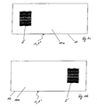
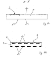
- FIG. 1 a shows in plan view a security document 1 in the form of a banknote with a security element 2 in reflected light.
- the banknote has a translucent carrier substrate 10 made of paper.
- the security element 2 is adhesively bonded in the form of a film element which comprises a layer 2a of aluminum simulating at least one first watermark.
- FIG. 1b shows the security document 1 FIG. 1a in section A - A '.
- Figure 1c shows the security document 1 FIG. 1a seen from the second side 10b in transmitted light.
- the security element 2 the viewer sees a watermark 2 'simulated by the security element 2.
- the watermark 2 ' is composed of five wavy curved bands having different transmission characteristics.
- the two bands arranged at the top and bottom have a lower transmission than the bands enclosed by them and thus have a darker effect in transmitted light.
- the security element 2 due to the at least one first watermark simulating layer 2a in reflected light shows a closed, reflective opaque surface made of aluminum, this surface is transmitted differently light transparent and visible divided into individual areas or bands with different shades of gray. This is achieved by the fact that the at least one first watermark simulating layer 2a is formed with a different layer thickness.
- the layer thickness of the layer 2a is in the range from 10 nm to 100 nm, in particular in the range from 10 to 50 nm. Adjacent regions with different layer thickness differ by 2 nm to 50 nm, in particular from 2 to 20 nm. However, this depends significantly which material is the layer simulating the first watermark 2a is formed.
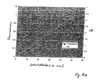
- the first watermark simulating layer 2a is formed of aluminum and it is in FIG. 8 Specifically, their transmission or optical density OD at normal illumination is shown as a function of the layer thickness (in nm) of an aluminum layer.
- the layer 2a simulating the at least one first watermark has an even smaller layer thickness than in the region of the middle band.
- the layer thicknesses of the layer 2a simulating the at least one first watermark are to be selected in each case such that different transmission or light transmission values are achieved in transmitted light. Since the observer perceives an opaque aluminum surface in reflected light, he is all the more surprised when the watermark 2 'that differs in shape and design unexpectedly shows itself in the transmitted light.
- FIG. 1 d now shows the security document 1 from the FIGS. 1 a to 1 c seen from the first page 10a in transmitted light.
- the watermark 2 ' is identical to the view from the second side 10b, only in side-reversed form.
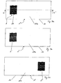
- FIG. 2a shows in plan view a security document 1 'in the form of a banknote with a security element 2 in incident light.
- the banknote has a translucent carrier substrate 10 made of paper.
- the security element 2 is imprinted in the form of a film element which comprises a layer 2a of aluminum simulating at least one first watermark.
- At least one first watermark simulating layer 2a Between the at least one first watermark simulating layer 2a and the viewer is a pattern-shaped printed translucent layer 3 with a star-shaped opening, which consists of a pigmented lacquer layer with a similar color as that adjacent support substrate 10 is formed and the actual dimensions of the, at least a first watermark simulating layer 2a conceals (here the shape of a cross, as indicated by dashed lines).
- the layer 2a simulating the first watermark is thus directly visible only in the region of the star-shaped opening in the translucent layer 3, while its remaining regions are invisible in reflected light.
- FIG. 2b shows the security document 1 'from FIG. 2a in section B - B '. It can be clearly seen that the star-shaped opening in the translucent layer 3 leaves only a part of the layer 2a simulating the first watermark uncovered.
- the security document 1 'from FIG. 2a a similar watermark 2 '(see Figure 1c ), as the security document 1 from FIG. 1a show, but with a cross-shaped outline.
- the security element 2 the viewer sees the watermark 2 'simulated by the security element 2.
- the security element 2 of the layer 2a simulating the at least one first watermark only shows a closed, star-shaped specular opaque surface made of aluminum, the layer 2a is subdivided into individual regions or bands with different light transmittances or gray levels when viewed through transmitted light.
- the opaque layer 2a which is opaque in incident light, is formed in regions with different layer thicknesses and / or has a multiplicity of openings whose spacing lies below 0.3 mm at least in one direction.
- the holes thus have, for example, in each case a diameter of approximately 2 to 100 ⁇ m or an area occupied by the respective hole of approximately 3 to 75 10 3 ⁇ m 2 and are in a grid with a screen width of 20 to 300 ⁇ m in the X direction and from 20 to 300 microns apart in the Y direction.
- the area fraction of the holes is between about 0.003 and 10%. Since the viewer perceives a star-shaped opaque aluminum surface in reflected light, he is all the more surprised, as in the transmitted light unexpectedly shows a different in shape and design watermark with a cross-shaped outline.
- FIG. 2a shows from the first page 10a from in transmitted light appearance similar to in Figure 1d shown, but with a cross-shaped outline.
- the simulated watermark is identical to the view from the second side 10b, only in a laterally inverted form.
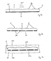
- FIG. 3a shows a further security document 1 "in the form of a banknote with a security element 2 impressed thereon.
- the layer 2a simulating the at least one first watermark is arranged by individual, in a regular grid of a screen width of 5 to 300 .mu.m, in particular from 10 to 100 .mu.m and aluminum pixels (not shown separately), which appear opaque in incident light, and between which the carrier substrate 10 is visible, at least under the microscope.
- the pixels cover 80 to 100% of the surface.
- a further reduction of the area ratio of the pixels can be achieved in that the reflection of the watermark simulating layer 2a is adapted to the reflection of the substrate or carrier substrate 10, for example by means of a scattering microstructure
- the layer 2a simulating the at least one first watermark shows a halftone or gray scale image of five in reflected light curved bands in two i different shades of gray.
- FIG. 3b shows the security document 1 "from FIG. 3a seen from the second side 10b in transmitted light. Due to different layer thicknesses of the individual pixels of the, at least one first watermark simulating layer 2a shows in the transmitted light, a first watermark 2 'with areas of different light transmission. Thus, the middle curved band is more translucent in the transmitted light than the bands above and below and also five vertical, filigree lines with high transparency are visible.
- Figure 3c shows the security document 1 "from FIG. 3a seen from the first page 10a in transmitted light.
- the viewer recognizes a second watermark 2 "which is reversed in relation to the first watermark 2 'and which does not show the five vertical, filigree lines with high light transmittance, which is realized in that the carrier substrate 10 transmits the light passing through in the area of the particularly transmissive trained filigree lines of Security elements 2 on the first page 10a scatters so much that they visually no longer appear in transmitted light.
- the security element 2 has a transparent hot-melt adhesive layer 3a, which has the at least one first watermark-simulating layer 2a and a transparent lacquer layer 3b and is adhesively bonded to the carrier substrate 10.
- the security element 2 is formed by the transfer layer of a transfer film and formed on the carrier substrate 10 in a transfer process.
- FIG. 3e shows a security document 1 "in the sectional view with an asymmetrically embedded in the support substrate 10 made of paper security element 2, which in principle as the security element 2 according to the FIGS. 3a to 3d is designed and gives a similar impression in transmitted light.
- the security element 2 is essentially not visible from any side 10a, 10b of the security document 1 "
- the security element 2 is designed as a laminating film and has a transparent lacquer layer 4a, which comprises the layer 2a simulating at least one first watermark and a transparent lacquer layer 4b
- a paper layer which scatters the transmitted light more strongly than between the security element 2 and the second side 10b
- the paper layer between the security element 2 and the first side 10a is thus for example 10 to 95% thicker in the case of a total layer thickness of the carrier substrate 10 of 50 ⁇ m to 2 mm, in particular of 50 ⁇ m to 1 mm, the embedding of the security element 2 into the carrier substrate 10 already takes place during papermaking.
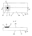
- FIG. 4a shows a further security document 1 '''in the form of a document with a security element 2, which has a viewing angle-dependent, optically variable effect in reflected light.
- the observer 100 of the security document 1 ''' shows from a first viewing direction a security element 2 with a layer 2a simulating the at least one first watermark, appearing opaque in incident light, a house being recognized as the first representation.
- the first representation is produced by diffractive first relief structures introduced into the layer 2a.
- the viewer 100 recognizes FIG. 4b likewise the security element 2 with a layer 2a which simulates the at least one first watermark and which appears opaque in incident light. From this line of sight, however, not the first representation, but due to introduced into the layer 2a, second relief structures to recognize a second representation in the form of a rose.
- the first and second relief structures are formed, for example, by diffraction gratings with different azimuth angles to one another or by different, asymmetrical relief structures, eg blazed gratings with different edge inclination.
- Figure 4c now shows the security document 1 '''from the FIGS. 4a and 4b in transmitted light and in a slightly enlarged representation. It shows neither the first nor the second representation, but a third representation in the form of a color-deposited rabbit as a watermark 2 ', which incidentally also shows from the first page 10a.
- the security element 2 is designed for realizing the security document 1 '''with a layer 2a of aluminum simulating at least one first watermark and containing diffractive structures arranged in a fine grid whose grid width is smaller than approximately 0 in at least one direction. 3 mm.
- a first group of grid surfaces contains the diffractive ones first structures, which serve in a viewing direction for generating the first representation.
- a second group of screen surfaces contains different diffractive second structures which serve to produce the second representation in a second viewing direction.
- a third group of grid surfaces contains openings which, viewed in transmitted light, increase the transmissivity in regions to produce the third representation.
- the opaque layer 2a which is opaque in incident light, has openings which are invisible to the human eye in incident light, but which are recognizable by transmitted light.
- the relative size and local frequency of the openings is varied in order to produce different halftones or gray levels in transmitted light.
- light-permeable color layers and / or transparent diffractive structures deposited with a transparent reflection layer can be arranged in order to produce color effects and / or optically variable effects in transmitted light.
- the openings have no disturbing influence on the first and second representations visible in reflected light, the grid surfaces having the openings are arranged alternately next to the diffractive grid surfaces.
- the regions of the at least one first watermark simulating layer 2a appear to be metallically reflective in incident light.
- a third structure in the form of a matt structure in the region of the perforated grid surface which has a similar scattering capacity as the carrier substrate 10, so that the regions of the layer 2a simulating the at least one first watermark correspond to the third representation are not obvious in reflected light.
- a light-absorbing diffractive fourth structure may also be present in the regions of the layer 2a simulating the at least one first watermark, which are to be assigned to the third representation, so that it appears dark in incident light.
- At least one translucent or transparent color layer is preferably arranged in the register to the openings, which in the incident light is hidden behind the layer 2a simulating at least one first watermark, but can be seen in the transmitted light and the third one Representation color or at least gives colored areas, where one or more colors may be present.
- a fourth group of grid areas with the third structures and a fifth group of grid areas with the fourth structures are occupied, thus providing a fourth and a fifth representation of the security element 2 in addition to the first, second and third representations which are formed in incident light from the third and fourth or third and fifth group of grid surfaces.
- a filigree Kinegram ® can be superimposed on the effects, which has little effect on the watermark effect and serves to distract the eye from the grid and hide it.
- the raster areas of the first to third group of raster areas are here preferably arranged alternately according to a regular raster, for example in the sequence, raster area of the first group, raster area of the second group, raster area of the third group, raster area of the first group, etc. in which the sequence repeatedly, less than 0,3 mm is chosen.
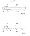
- FIG. 5a shows another security document 1 '''in the form of a document with a security element 2 (see also FIG. 5c ), which is embedded in the support substrate 10 of light-diffusing paper adjacent to the surface and, seen in transmitted light from the first side 10a, simulates the presence of a three-dimensional watermark 2 '.
- the security element 2 has at least two layers 2a ', 2a "of opaque, black-colored lacquer that simulate at least one first watermark (see FIG. 5d ), which are arranged spaced apart by a spacer film 5 made of plastic film, which acts as a filter for light in certain directions, and allows scattered light of only a certain angular range to arrive from the second side 10b.
- the two layers 2a ', 2a "simulating the at least one first watermark are each provided with openings, the openings being superimposed with one another in such a way that different regions of the security element 2 allow light to pass through in the transmitted light depending on the viewing angle according to a first viewing angle
- FIG. 5a a first three-dimensional representation, here a folded band.
- the security document 1 '''according to FIG. 5b viewed from a different angle in transmitted light, so shows the three-dimensional volume from another perspective due to the shift or change in position of the translucent areas.
- the change in perspective can be continuously observable or erratic as the angle of view changes.
- FIG. 5c shows the security document FIG. 5a and the embedded in the support substrate 10 security element 2 in a simplified form in cross section.
- FIG. 5d shows the security element 2 FIG. 5c alone and in an enlarged view in cross section. It shows the spacer layer 5, which has on each side in each case one of the at least one first watermark simulating layers 2a ', 2a ", which are each provided with openings through which passes depending on the acting as a filter spacer layer 5 light certain angular orientation Furthermore, an optically variable element 6 in the form of a volume hologram, amplitude hologram or a diffractive surface structure is present, which is very good in transmitted light but substantially indistinguishable in incident light.
- FIG. 6a shows another security document 1 with a embedded in a support substrate 10 of light-scattering paper adjacent to the surface security element which seen in transmitted light from the first side 10a, the presence of a moving watermark 2 'simulated when the viewing angle is changed.
- the security element points, as already from the principle in the FIGS. 5a to 5d shown, at least two, at least a first watermark simulating layers, which are spaced apart by a spacer acting as a filter and each provided with openings, wherein the openings are superposed with each other such that in the transmitted light depending on the viewing angle different areas of the security element light let through.
- FIG. 6b shows the security document 1 FIG. 6a also in transmitted light, but from a different angle. It shows up due to the shift or change in position of the translucent areas, the watermark 2 in a second representation, or the annulus in a different spatial orientation. In this case, the change in the position of the circular ring with change in the angle of view can be continuously observable or take place abruptly.
- Figure 7a shows the production of a security element 2 according to FIG. 7b for generating in cross-section a watermark effect visible only on one side of a security document.
- a film carrier 7 made of transparent PET with a layer thickness in the range of 12 to 50 ⁇ m is covered on one side with a UV-curing replication lacquer layer 8 and replicated in these microlenses 8a.
- the microlenses 8a are preferably of refractive design and have a thickness or structure depth of usually 2 to 50 ⁇ m and a diameter (seen perpendicular to the plane of the replication lacquer layer 8) of usually 5 to 100 ⁇ m.
- a metal layer 12 made of aluminum with a layer thickness of 50 nm is applied over the entire surface, in which information, in particular in the form of a € -character is introduced.
- the information is formed by covering the metal layer 12 formed over the entire area with a positive photoresist layer 9 on its side facing away from the film carrier 7.
- a UV exposure (see arrows) is performed from the side of the microlenses 8a. The UV light strikes and is focused by the microlenses 8a, so that a single light beam leaves the replication lacquer layer 8 per microlens 8a.
- the light beams pass through the film carrier 7 to the metal layer 12 and - due to a sufficient transmission of the 50 nm thick aluminum layer for UV radiation - therethrough to the positive photoresist layer 9.
- the exposed areas of the photoresist layer 9 are then removed in a washing process and the exposed areas the metal layer 12 removed by etching. Openings 11 are formed in the metal layer which are aligned in perfect registry with the microlenses 8a.
- the photoresist layer 9 is removed and the apertured metal layer 12, which has now become a first watermark simulating layer 2a, is exposed (see figure 7b ).
- the openings in the metal layer can also be produced by laser ablation, whereby a metal layer of aluminum in a layer thickness of 20 nm or a layer of tellurium in a layer thickness of 50 nm has proved successful.
- FIG. 7b shows that according to Figure 7a produced security element 2 in cross section, which can simulate embedded in a support substrate of a security document, a watermark with a particularly unusual optical effect.
- FIG. 7c now shows in cross section the security element 2 according to FIG. 7b which has been completely embedded in a carrier substrate 10 of a security document made of paper and glued on both sides with this.
- the carrier substrate 10 is comparatively weakly scattering and thin.
- a transparent adhesive layer 13a, 13b is present on both sides of the security element 2 over the entire area or only partially (for example in the form of a line or dot matrix).
- the layer thickness of the adhesive layer 13b, which is arranged adjacent to the microlenses 8a, is negligibly small with respect to the structural depth of the microlenses 8a to choose, so that the optical effect of the security element 2 is not impaired.
- the adhesive layer 13a adjacent to the first watermark simulating layer 2a can be made substantially thicker.
- the security element 2 is visible in reflected light neither from the first side 10a nor from the second side 10b of the carrier substrate 10.
- the viewer From the first side 10a of the carrier substrate 10, the viewer sees in transmitted light a first watermark with a slightly dynamic movement effect, which conveys information in the form of a € symbol, after the layer 2a simulating the first watermark through the openings 11 is only a part lets in the incoming light. Seen from the second side 10b, however, the viewer does not show any watermark in the transmitted light, since the lenses cause all incident light to be ignited and to pass through the openings 11.
- the subsequent material of the carrier substrate 10 evenly disperses the collimated light before the light comes to the observer's eye, so that, to the astonishment of the observer, viewed from the second side 10b, none Brightness differences or no watermark in the carrier substrate 10 can be perceived.
- FIG. 8a shows a diagram of the dependence of the transmission or optical density OD of an aluminum layer of the layer thickness d (in nm) under normal illumination.
- the viewer perceives the aluminum layer as translucent if a transmission of greater than 10%, in particular greater than 20%, is present. This is the case for aluminum with a layer thickness of up to about 10 to 15 nm.
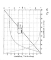
- FIG. 8b shows a diagram of the dependence of the transmission / reflection or the optical density OD of a silver layer of the layer thickness d (in nm) under normal illumination.
- the viewer perceives the silver layer as translucent if a transmission of greater than 10%, in particular greater than 20%, is present. This is the case for silver with a layer thickness of up to about 19 to 27 nm.
- the result for a layer thickness of 40 nm is a transmission of less than 10%, ie an opaque layer.
Landscapes
- Business, Economics & Management (AREA)
- Accounting & Taxation (AREA)
- Finance (AREA)
- Credit Cards Or The Like (AREA)
- Inspection Of Paper Currency And Valuable Securities (AREA)
- Diffracting Gratings Or Hologram Optical Elements (AREA)
- Transition And Organic Metals Composition Catalysts For Addition Polymerization (AREA)
Abstract
Description
Die Erfindung betrifft ein Sicherheitsdokument, umfassend ein transluzentes Trägersubstrat, insbesondere aus Papier und/oder Kunststoff, und mindestens ein auf das Trägersubstrat aufgebrachtes oder in das Trägersubstrat eingebettetes Sicherheitselement, welches von mindestens einer ersten Seite des Sicherheitsdokuments aus gesehen im Durchlicht mindestens ein erstes Bild zeigt und ein Vorhandensein mindestens eines ersten Wasserzeichens im Trägersubstrat simuliert, wobei das Sicherheitselement zumindest bereichsweise mindestens eine, das mindestens eine erste Wasserzeichen simulierende Schicht aufweist, welche die visuell wahrnehmbare Transluzenz des Trägersubstrats lokal verändert.The invention relates to a security document, comprising a translucent carrier substrate, in particular made of paper and / or plastic, and at least one embedded on the carrier substrate or embedded in the carrier substrate security element, which seen from at least a first side of the security document in transmitted light at least a first image and a presence of at least one first watermark in the carrier substrate is simulated, wherein the security element at least partially at least one, the at least one first watermark simulating layer which changes the visually perceptible translucency of the carrier substrate locally.
Derartige Sicherheitsdokumente sind aus
Ein derartiges Sicherheits dokument wird auch in
Ein herkömmliches Wasserzeichen in Papier wird dadurch erzeugt, dass die Dicke des Papiers bei dessen Herstellung lokal verändert wird, so dass sich Transmissionsunterschiede im Papier ergeben. Im Durchlicht ist für einen Betrachter von beiden seiten des Papiers ein kontinuierliches Graustufenbild, das so genannte Wasserzeichen, erkennbar.A conventional watermark in paper is created by locally changing the thickness of the paper as it is made, thus resulting in transmission differences in the paper. In transmitted light is for a viewer from both sides of the paper a continuous grayscale image, the so-called watermark, recognizable.
Eine Simulation eines Wasserzeichens durch ein Sicherheitselement besitzt den Vorteil, dass der aufwendige Herstellungsprozess, wie er bei der herkömmlicher Wasserzeichenbildung an Papiersubstraten erforderlich ist, vermieden werden kann. Weiterhin kann mittels eines simulierten Wasserzeichens auch ein transluzentes Kunststoffsubstrat in einfacher Weise mit einem Wasserzeicheneffekt ausgestattet werden. Lediglich ein Einbetten oder Aufbringen eines unabhängig vom transluzenten Trägersubstrat des Sicherheitsdokuments gebildeten Sicherheitselements in oder auf das transluzente Trägersubstrat, ob nun aus Papier, Kunststoff, oder auch Teslin®, bzw. Laminaten aus diesen Materialien, ist erforderlich. Je nach Ausgestaltung des Sicherheitselements sind dabei unterschiedlichste Wasserzeichen in ein und demselben Trägersubstrat simulierbar.A simulation of a watermark by a security element has the advantage that the complicated production process, as required in conventional watermarking on paper substrates, can be avoided. Furthermore, by means of a simulated watermark and a translucent plastic substrate can be easily equipped with a watermark effect. Only embedding or applying a security element formed independently of the translucent carrier substrate of the security document into or onto the translucent carrier substrate, whether made of paper, plastic, or Teslin® , or laminates of these materials, is required. Depending on the configuration of the security element, a wide variety of watermarks can be simulated in one and the same carrier substrate.
Jedoch hat es sich gezeigt, dass die Simulation von Wasserzeichen mittels separaten Sicherheitselementen an einem Sicherheitsdokument auch für einen Fälscher mit vertretbarem Aufwand durchführbar ist. Dazu wird beispielsweise zwischen den Papierlagen ein Aufdruck angeordnet oder eine Maskenschicht eingeklebt, um das gewünschte Graustufenbild zu simulieren.However, it has been found that the simulation of watermarks by means of separate security elements on a security document can also be carried out by a counterfeiter at a reasonable cost. For this purpose, for example, a print is arranged between the paper layers or glued in a mask layer in order to simulate the desired gray scale image.
Es ist daher Aufgabe der Erfindung, ein Sicherheitsdokument bereitzustellen, das einen besonders schwer nachahmbaren, durch ein Sicherheitselement simulierten Wasserzeicheneffekt aufweist.It is therefore an object of the invention to provide a security document which has a particularly difficult to imitate, simulated by a security element watermark effect.
Die Aufgabe wird mit einem Sicherheitsdokument gemäß Anspruch 1 gelöst.The object is achieved with a security document according to
Dabei ist als Beleuchtung üblicherweise Tageslicht oder Kunstlicht vorgesehen. Allerdings können sich diese oder weitere optischen Effekte auch bei zusätzlicher ultravioletter oder infraroter Bestrahlung zeigen, sofern die mindestens eine, das erste Wasserzeichen simulierende Schicht einen oder mehrere Stoffe (wie beispielsweise lumineszierende, thermochrome, photochrome Stoffe und ähnliches) enthält, die mit einer derartigen Strahlung angeregt werden können.It is usually provided as lighting daylight or artificial light. However, these or other optical effects may also show up with additional ultraviolet or infrared radiation, provided that the at least one, the first watermark simulating layer contains one or more substances (such as luminescent, thermochromic, photochromic substances and the like), with such radiation can be stimulated.
Die erfindungsgemäße Ausgestaltung des Sicherheitsdokuments verleiht diesem neben einem simulierten Wasserzeicheneffekt weiterhin interessante und unerwartete Effekte in direktem Zusammenhang mit dem simulierten Wasserzeichen.The inventive design of the security document gives this in addition to a simulated watermark effect further interesting and unexpected effects in direct connection with the simulated watermark.
Bei herkömmlichen, in das Trägersubstrat eingebetteten, ein Wasserzeichen simulierenden Sicherheitselementen sieht ein Betrachter im Durchlicht von jeder Seite des Sicherheitsdokuments das gleiche Wasserzeichenbild, bei asymmetrischen Motiven lediglich in seitenverkehrter Form. Wird das Sicherheitselement auf eine Seite des Trägersubstrats aufgebracht, so zeigt sich dem Betrachter üblicherweise unmittelbar diejenige Schicht oder diejenigen Schichten, die im Durchlicht die Transmission des Trägersubstrats beeinflussen. Der Betrachter erwartet dabei, dass zumindest die Form von opaken Schichten dem entspricht, was er auf der anderen Seite als Wasserzeichen, gegebenenfalls in seitenverkehrter Form, wahrnimmt. Bei der Betrachtung des erfindungsgemäßen Sicherheitsdokuments zeigt sich dem Betrachter jedoch ein unerwarteter optischer Eindruck, da die gewohnten Wasserzeicheneffekte in dieser Form nicht oder nur zum Teil eintreten.In conventional security elements simulating a watermark which are embedded in the carrier substrate, a viewer sees in transmitted light from each side of the security document the same watermark image, in asymmetrical images only in a laterally inverted form. If the security element is applied to one side of the carrier substrate, the viewer is usually immediately exposed to that layer or those layers which influence the transmission of the carrier substrate in transmitted light. The observer expects that at least the shape of opaque layers corresponds to what he perceives on the other side as a watermark, possibly in a laterally reversed form. When considering the security document according to the invention shows the Viewers, however, an unexpected visual impression, since the usual watermark effects occur in this form, or only partially.
Als transluzentes Trägersubstrat hat sich hierbei insbesondere Papier und/oder Kunststoff und/oder Teslin® bzw. ein Verbund aus derartigen Materialien bewährt. Dabei bedeutet der Begriff "transluzent", dass das Trägersubstrat zwar lichtdurchlässig ist, jedoch nicht durchsichtig bzw. transparent. Im Trägersubstrat tritt eine Volumenstreuung auf und das hindurchtretende Licht wird je nach Materialauswahl und Materialdicke mehr oder weniger stark gestreut.In particular, paper and / or plastic and / or Teslin® or a composite of such materials has proven to be a translucent carrier substrate. The term "translucent" means that the carrier substrate is translucent, but not transparent or transparent. In the carrier substrate, a volume scattering occurs and the light passing through is scattered more or less strongly depending on the material selection and material thickness.
Die mindestens eine, das erste Wasserzeichen simulierende Schicht ist bevorzugt durch mindestens eine Metallschicht und/oder mindestens eine dielektrische Schicht insbesondere mit hohem Brechungsindex und/oder mindestens eine Chalkogenidglas-Schicht und/oder eine pigmentierte Schicht, insbesondere eine pigmentierte Farbschicht oder Tinte, und/oder eine Flüssigkristallschicht ausgebildet. Besonders bewährt hat sich hierbei eine Kombination mindestens einer Metallschicht und mindestens einer pigmentierten Schicht.The at least one layer simulating the first watermark is preferably by at least one metal layer and / or at least one dielectric layer, in particular having a high refractive index and / or at least one chalcogenide glass layer and / or a pigmented layer, in particular a pigmented ink layer or ink, and / or or a liquid crystal layer is formed. In this case, a combination of at least one metal layer and at least one pigmented layer has proved particularly useful.
Wird das Sicherheitsdokument im Auflicht betrachtet, so wird hier von einer Betrachtung durch ein menschliches Auge unter Normalbedingungen, also bei Tageslicht oder Kunstlicht, ausgegangen, wobei das Licht von der Seite des Betrachters auf das Sicherheitsdokument auftrifft.If the security document is viewed in reflected light, then it is assumed here that it is viewed by a human eye under normal conditions, ie in daylight or artificial light, with the light from the side of the observer striking the security document.
Wird das Sicherheitselement im Durchlicht betrachtet, so wird von einer Betrachtung durch das menschliche Auge unter Normalbedingungen ausgegangen, wobei das Licht von der Rückseite des Sicherheitsdokuments, also der dem Betrachter abgewandten Seite des Sicherheitsdokuments, auf dieses auftrifft.If the security element is viewed in transmitted light, it is assumed to be under normal conditions by the human eye, the light from the back of the security document, ie the side of the security document facing away from the viewer, impinging on it.
Es hat sich bewährt, wenn in Fall a) die, das mindestens eine erste Wasserzeichen simulierende Schicht Bereiche mit unterschiedlicher Transmissivität aufweist.It has proven useful if, in case a), the layer simulating at least one first watermark has regions with different transmissivity.
Es hat sich dabei bewährt, wenn in Fall a) das Sicherheitselement auf der zweiten Seite des Sicherheitsdokuments aufgebracht ist oder derart in das transluzente Trägersubstrat eingebettet ist, dass das Sicherheitselement sich in einer Ebene parallel zu der ersten Seite und der zweiten Seite befindet und ein Bereich des Trägersubstrats, welcher sich auf der zweiten Seite zwischen der mindestens einen das Wasserzeichen simulieren Schicht und einem Betrachter befindet, zumindest teilweise ausgespart ist, wobei von der zweiten Seite sichtbare Bereiche der das erste Wasserzeichen simulierenden Schicht im Auflicht visuell als geschlossene, opake Schichtbereiche zu erkennen sind, jedoch zumindest die sichtbaren Bereiche der das erste Wasserzeichen simulierenden Schicht im Durchlicht unterschiedlich transmissiv sind.It has proven useful in case a) the security element is applied on the second side of the security document or is embedded in the translucent carrier substrate such that the security element is in a plane parallel to the first side and the second side, and a portion of the support substrate located on the second side between the at least one watermark simulating layer and a viewer is at least partially recessed, areas visible from the second side being the first one Watermark simulating layer can be seen visually in the reflected light as a closed, opaque layer areas, but at least the visible areas of the first watermark simulating layer in the transmitted light are different transmissive.
So erkennt der Betrachter bei einem Sicherheitsdokument gemäß Fall a) wie gewohnt bei Betrachtung der ersten Seite im Durchlicht das erste Wasserzeichen. Auf der zweiten Seite sieht der Betrachter im Auflicht das auf das Trägersubstrat aufgebrachte Sicherheitselement und die mindestens eine das erste Wasserzeichen simulierende Schicht, deren Form allerdings mit der Form des ersten Wasserzeichens wider Erwarten nicht übereinstimmt. Im Durchlicht ist jedoch auch von der zweiten Seite wieder das - gegebenenfalls seitenverkehrte - erste Wasserzeichen erkennbar. Dieser Effekt wird erreicht, indem die mindestens eine, das mindestens eine erste Wasserzeichen simulierende Schicht mit Bereichen unterschiedlicher Transmissivität ausgebildet wird, welche lediglich im Durchlicht visuell voneinander unterscheidbar sind.Thus, the observer recognizes the first watermark in the case of a security document according to case a) as usual when viewing the first page in transmitted light. On the second side, the observer sees in the incident light the security element applied to the carrier substrate and the at least one layer simulating the first watermark, the shape of which, however, does not coincide with the shape of the first watermark contrary to expectations. In transmitted light, however, the first watermark is recognizable from the second side as well - possibly reversed from one side to the other. This effect is achieved by forming the at least one layer which simulates at least one first watermark with regions of different transmissivity, which are visually distinguishable from one another only in transmitted light.
Bei einem Papier- oder Kunststoffträgersubstrat kann der letztere Fall, dass das Sicherheitselement sich in einer Ebene parallel zu der ersten Seite und der zweiten Seite des Sicherheitsdokuments befindet und ein Bereich des Trägersubstrats, welcher sich auf der zweiten Seite zwischen der mindestens einen opaken Schicht und einem Betrachter befindet, ausgespart ist, realisiert werden, indem das Trägersubstrat mindestens aus zwei Lagen ausgebildet wird und das mindestens eine Sicherheitselement zwischen diesen Lagen angeordnet wird. Vor dem Zusammenfügen der Lagen wird eine davon mit einer Fensteröffnung versehen und die Fensteröffnung derart über dem Sicherheitselement platziert, dass die mindestens eine im Auflicht opake Schicht sichtbar ist.In a paper or plastic carrier substrate, the latter case may be that the security element is in a plane parallel to the first side and the second side of the security document, and a portion of the carrier substrate located on the second side between the at least one opaque layer and one Viewer is located, is recessed, realized by the carrier substrate is formed of at least two layers and the at least one security element is disposed between these layers. Before assembling the layers, one of them is provided with a window opening and the window opening is placed over the security element such that the at least one opaque layer is visible in the incident light.
Unter einer Fensteröffnung wird dabei, wie im Übrigen auch nachfolgend im Text, nicht nur eine Öffnung verstanden, sondern auch ein durchsichtiger bzw. transparenter Bereich, beispielsweise aus glasklarem Kunststoff.Under a window opening is, as well as below in the text, understood not only an opening, but also a transparent or transparent area, for example, made of transparent plastic.
Alternativ könnte auch eine Fensteröffnung in beide Lagen eingebracht werden und das mindestens eine Sicherheitselement mit beiden Fensteröffnungen zur Überdeckung gebracht werden. Anschließend wird das Sicherheitselement auf der ersten Seite mit mindestens einer transluzenten Farbschicht überdeckt, so dass die das mindestens eine erste Wasserzeichen simulierende Schicht lediglich von der zweiten Seite erkennbar ist.Alternatively, a window opening could also be introduced into both layers and the at least one security element be brought into coincidence with both window openings. Subsequently, the security element is covered on the first side with at least one translucent ink layer, so that the layer simulating the at least one first watermark can only be seen from the second side.
Generell kann mindestens eine transluzente Farbschicht aber auch bereits ein Bestandteil des Sicherheitselements sein, so dass sich ein Auftrag nach dem Einbetten des Sicherheitselements in das Trägersubstrat erübrigen kann. Eine transluzente Farbschicht kann weiterhin durch eine transluzente Kleberschicht gebildet sein, die beim Einbetten des Sicherheitselements zwischen die Lagen des Trägersubstrats zur Verklebung mit einer Lage verwendet wird. Im Hinblick, auf eine optische Verschleierung des Vorhandenseins von Fensteröffnungen im Trägersubstrat kann eine Integration von transluzenten Farbschichten in das Sicherheitselement in Kombination mit einem zusätzlichen Aufbringen von transluzenten Farbschichten nach dem Einbetten des Sicherheitselements oder einer Verwendung transluzenter Kleberschichten zum Einbetten von Vorteil sein.In general, however, at least one translucent ink layer can also already be a component of the security element, so that a job after the embedding of the security element in the carrier substrate can be dispensed with. A translucent ink layer may further be formed by a translucent adhesive layer which is used to embed the security element between the layers of the carrier substrate for bonding to a layer. With regard to optical concealment of the presence of window openings in the carrier substrate, integration of translucent color layers into the security element in combination with additional application of translucent color layers after embedding the security element or using translucent adhesive layers for embedding may be advantageous.
Weiterhin ist es von Vorteil, wenn in Fall a) die mindestens eine, das Wasserzeichen simulierende Schicht im Auflicht gesehen eine andere Flächenausdehnung zeigt als im Durchlicht erkennbar.Furthermore, it is advantageous if, in case a), the at least one layer simulating the watermark shows a different surface area as seen in transmitted light, as seen in transmitted light.
Weiterhin hat es sich bewährt, wenn in Fall a) die das erste Wasserzeichen simulierende Schicht auf der zweiten Seite des Sicherheitsdokuments aufgebracht ist und bereichsweise durch mindestens eine, auf der zweiten Seite angeordnete transluzente Farbschicht bedeckt ist, oder derart in das transluzente Trägersubstrat eingebettet ist, dass das Sicherheitselement sich in einer Ebene parallel zu der ersten Seite und der zweiten Seite befindet und ein Bereich des Trägersubstrats, welcher sich auf der zweiten Seite zwischen der mindestens einen, das erste Wasserzeichen simulierenden Schicht und einem Betrachter befindet, entweder teilweise ausgespart ist oder aber gänzlich ausgespart ist und bereichsweise durch mindestens eine, auf der zweiten Seite angeordnete transluzente Farbschicht bedeckt ist, wobei die von der zweiten Seite sichtbaren Bereiche der das erste Wasserzeichen simulierenden Schicht im Auflicht visuell als bereichsweise ausgeformte opake Schichtbereiche zu erkennen sind, welche eine Sicherheitsinformation zeigen, und sich im Durchlicht von der zweiten Seite das mindestens eine erste Wasserzeichen zeigt, welches sich von der Sicherheitsinformation unterscheidet.Furthermore, it has proven useful if in case a) the layer simulating the first watermark is applied to the second side of the security document and is partially covered by at least one translucent ink layer arranged on the second side, or embedded in the translucent carrier substrate, in that the security element is located in a plane parallel to the first side and the second side, and a region of the carrier substrate located on the second side between the at least one, the first Watermark simulating layer and a viewer located, either partially recessed or completely recessed and is partially covered by at least one arranged on the second side of the translucent color layer, wherein the visible from the second side of the first watermark simulating layer in incident light visually as a partially formed opaque layer areas are to be recognized, which show a security information, and shows in the transmitted light from the second side, the at least one first watermark, which differs from the security information.
Ein Betrachter erkennt bei einem Sicherheitsdokument gemäß Fall a) ebenfalls wie gewohnt bei Betrachtung der ersten Seite im Durchlicht ein erstes Wasserzeichen. Auf der zweiten Seite sieht der Betrachter im Auflicht das auf das Trägersubstrat aufgebrachte Sicherheitselement bzw. bereichsweise ausgeformte opake Bereiche der das erste Wasserzeichen simulierenden Schicht, welche eine Sicherheitsinformation zeigen, deren Form allerdings mit der Form des ersten Wasserzeichens wider Erwarten nicht übereinstimmt. Im Durchlicht ist auch von der zweiten Seite wieder das - nun gegebenenfalls seitenverkehrte - Wasserzeichen erkennbar. Dieser Effekt wird einerseits erreicht, indem - vom Betrachter im Auflicht nicht erkennbar - nur Teile der vollflächig oder bereichsweise ausgeformten, das erste Wasserzeichen simulierenden Schicht unmittelbar sichtbar angeordnet sind. Dabei kann die das erste Wasserzeichen simulierende Schicht zudem mit Bereichen unterschiedlicher Transmissivität ausgestattet sein, welche lediglich im Durchlicht visuell voneinander unterscheidbar sind. Andererseits kann der Effekt auch erreicht werden, indem die mindestens eine im Auflicht opake Schicht - für das menschliche Auge ohne weiteres sichtbar - lediglich bereichsweise ausgebildet und komplett sichtbar ist und weiterhin Bereiche unterschiedlicher Transmissivität aufweist, welche lediglich im Durchlicht visuell voneinander unterscheidbar sind.A viewer recognizes in a security document according to case a) also as usual when viewing the first page in transmitted light, a first watermark. On the second side, the observer sees the security element applied to the carrier substrate or partially formed opaque regions of the first watermark simulating layer in the reflected light, which show security information, however, the shape of which does not coincide with the shape of the first watermark contrary to expectations. In transmitted light, the watermark can now be seen from the second page as well - now possibly reversed. On the one hand, this effect is achieved by the fact that, visible to the viewer in the reflected light, only parts of the layer which is formed over the whole area or in regions and which simulate the first watermark are arranged so as to be immediately visible. In this case, the layer simulating the first watermark can also be equipped with regions of different transmissivity, which are visually distinguishable from one another only in transmitted light. On the other hand, the effect can also be achieved by the at least one opaque layer-which is readily visible to the human eye-only partially formed and completely visible and further having regions of different transmissivity, which are visually distinguishable from each other only in transmitted light.
Hierbei wird vom menschlichen Betrachter ein Bereich der, das erste Wasserzeichen simulierenden Schicht im Durchlicht als opak empfunden, wenn die Transmission für sichtbares Licht kleiner als 5 %, insbesondere kleiner als 1 % beträgt. Als transluzent empfindet ein Betrachter im Durchlicht Bereiche mit einer Transmission für sichtbares Licht von größer als 10 %, insbesondere von größer als 20 %. Im Auflicht kann sich für einen Betrachter allerdings auch in den, im Durchlicht transluzent wahrgenommenen Bereichen, der Eindruck eines opaken Schichtbereichs ergeben. Wird beispielsweise eine metallische Schicht als die, das erste Wasserzeichen simulierende Schicht eingesetzt, so reflektieren die im Durchlicht opak und transluzent empfundenen Bereiche im Auflicht betrachtet maximal um einen Faktor 10 unterschiedlich. Eine um den Faktor 10 unterschiedliche Reflexion ist für das menschliche Auge gut erkennbar, während ein Unterschied in der Reflektion von bis zu ca. 20 % kaum mehr wahrnehmbar ist.In this case, an area of the layer simulating the first watermark in transmitted light is perceived by the human observer to be opaque if the transmission for visible light is less than 5%, in particular less than 1%. As a translucent, a viewer perceives in transmitted light areas with a transmission for visible light of greater than 10%, in particular greater than 20%. In reflected light can be For a viewer, however, even in the areas that are translucent in transmitted light, the impression of an opaque layer area results. If, for example, a metallic layer is used as the layer simulating the first watermark, then the areas which are opaque and translucent in transmitted light reflect a maximum of a factor of 10 when viewed in reflected light. A reflection that is different by a factor of 10 is easily recognizable to the human eye, while a difference in reflection of up to approximately 20% is barely perceptible.
Wird also der Faktor möglichst klein gewählt und/oder das Reflektionsverhalten der, das erste Wasserzeichen simulierenden Schicht dem des Untergrunds angepasst, so kann das menschliche Auge die Unterschiede im Auflicht nicht auflösen und nimmt eine gleichmäßig opake Fläche wahr.Thus, if the factor chosen is as small as possible and / or the reflection behavior of the layer simulating the first watermark is matched to that of the background, then the human eye can not resolve the differences in reflected light and perceives a uniformly opaque surface.
Bei einem Trägersubstrat aus beispielsweise Papier und/oder Kunststoff kann der Fall, dass das Sicherheitselement in das transluzente Trägersubstrat eingebettet ist und sich in einer Ebene parallel zu der ersten Seite und der zweiten Seite befindet, wobei ein Bereich des Trägersubstrats, welcher sich auf der zweiten Seite zwischen der mindestens einen, das erste Wasserzeichen simulierenden Schicht und einem Betrachter befindet, zumindest teilweise ausgespart ist, realisiert werden, indem das Trägersubstrat mindestens aus zwei Lagen ausgebildet wird und das mindestens eine Sicherheitselement zwischen diesen Lagen angeordnet wird. Vor dem Zusammenfügen der Lagen wird eine davon mit einer Fensteröffnung versehen und die Fensteröffnung derart über dem Sicherheitselement platziert, dass die mindestens eine, das erste Wasserzeichen simulierende Schicht nur teilweise sichtbar ist. Alternativ könnte die, das erste Wasserzeichen simulierende Schicht auch vollständig sichtbar sein und diese anschließend mit der transluzenten Farbschicht bereichsweise abgedeckt werden. Weiterhin ist es auch hier möglich, dass eine Fensteröffnung in beide Lagen eingebracht ist und das mindestens eine Sicherheitselement mit beiden Fensteröffnungen zur Überdeckung gebracht ist. Anschließend wird das Sicherheitselement auf der ersten Seite teilweise oder vollständig mit einer transluzenten Farbschicht überdeckt und auf der zweiten Seite mit der transluzenten Farbschicht bereichsweise abgedeckt, so dass die, das erste Wasserzeichen simulierende Schicht auf der zweiten Seite im Auflicht lediglich teilweise sichtbar ist. Auf der ersten Seite ist die mindestens eine, das erste Wasserzeichen simulierenden Schicht nicht oder ebenfalls nur teilweise zu erkennen. Ist die mindestens eine, das erste Wasserzeichen simulierende Schicht auch auf der ersten Seite teilweise im Auflicht zu erkennen, so ist es bevorzugt, wenn auf der ersten Seite und der zweiten Seite im Auflicht unterschiedliche Bereiche der mindestens einen, das erste Wasserzeichen simulierenden Schicht sichtbar sind.In the case of a carrier substrate of, for example, paper and / or plastic, the case may be that the security element is embedded in the translucent carrier substrate and is located in a plane parallel to the first side and the second side, wherein a region of the carrier substrate which is located on the second Side between the at least one, the first watermark simulating layer and a viewer is located, at least partially recessed, realized by the carrier substrate is formed at least from two layers and the at least one security element between these layers is arranged. Before assembling the layers, one of them is provided with a window opening and the window opening is placed over the security element in such a way that the at least one layer simulating the first watermark is only partially visible. Alternatively, the, the first watermark simulating layer could also be completely visible and these are then partially covered with the translucent color layer. Furthermore, it is also possible here for a window opening to be introduced in both layers and for the at least one security element to be brought into overlap with both window openings. Subsequently, the security element on the first page is partially or completely covered with a translucent color layer and partially covered on the second side with the translucent color layer, so that the, the first watermark simulating layer on the second side in incident light only partially visible. On the first page, the at least one, the first watermark simulating layer is not or only partially visible. If the at least one layer simulating the first watermark is also partly visible in incident light on the first side, then it is preferred if different regions of the at least one layer simulating the first watermark are visible on the first side and the second side in incident light ,
Generell kann auch hier mindestens eine transluzente Farbschicht bereits ein Bestandteil des Sicherheitselements sein oder transluzente Klebstoffschichten zum Einbetten verwendet werden, so dass sich ein Auftrag nach dem Einbetten des Sicherheitselements in das Trägersubstrat erübrigen kann. Im Hinblick auf eine optische Verschleierung des Vorhandenseins von Fensteröffnungen im Trägersubstrat kann eine Integration von transluzenten Farbschichten in das Sicherheitselement in Kombination mit einem zusätzlichen Aufbringen von transluzenten Farbschichten nach dem Einbetten des Sicherheitselements oder einer Verwendung transluzenter Klebstoffschichten zum Einbetten von Vorteil sein.In general, at least one translucent ink layer may also already be a constituent of the security element or translucent adhesive layers may be used for embedding, so that an application after embedding the security element in the carrier substrate may be unnecessary. With regard to an optical concealment of the presence of window openings in the carrier substrate, integration of translucent color layers into the security element in combination with an additional application of translucent color layers after embedding the security element or using translucent adhesive layers for embedding can be advantageous.
Für den im erfindungsgemäßen Sicherheitsdokument vorausgesetzten Fall b) ist es bevorzugt, wenn die mindestens eine, das erste Wasserzeichen simulierende Schicht auf der ersten Seite und einer der ersten Seite gegenüberliegenden zweiten Seite des Sicherheitsdokuments jeweils zumindest teilweise von mindestens einer transluzenten Schicht bedeckt ist, wobei die mindestens eine transluzente Schicht auf der ersten Seite und die mindestens eine transluzente Schicht auf der zweiten Seite einfallendes Licht unterschiedlich stark streuen.For the case b) presupposed in the security document according to the invention, it is preferred if the at least one first watermark simulating layer on the first side and a second side of the security document opposite the first side is at least partially covered by at least one translucent layer at least one translucent layer on the first side and the at least one translucent layer on the second side scatter light to different degrees.
Schließlich hat es sich bewährt, wenn in Fall b) das Sicherheitselement auf der zweiten Seite angeordnet und die das Wasserzeichen simulierende Schicht durch mindestens eine, auf der zweiten Seite angeordnete transluzente Farbschicht bedeckt ist, oder das Sicherheitselement derart in das transluzente Trägersubstrat eingebettet ist, dass das Sicherheitselement sich in einer Ebene parallel zu der ersten Seite und der zweiten Seite, jedoch in ungleichem Abstand zur ersten Seite und zur zweiten Seite befindet, oder das Sicherheitselement in das transluzente Trägersubstrat eingebettet und die das Wasserzeichen simulierende Schicht durch mindestens eine, auf der ersten Seite und/oder der zweiten Seite angeordnete transluzente Farbschicht bedeckt ist, wobei die das erste Wasserzeichen simulierende Schicht von der zweiten Seite im Durchlicht gesehen mindestens ein zweites Bild zeigt, das ein Vorhandensein mindestens eines, zum ersten Wasserzeichen unterschiedlichen zweiten Wasserzeichens im Trägersubstrat simuliert.Finally, in case b), the security element has been arranged on the second side and the watermark simulating layer is covered by at least one translucent color layer arranged on the second side, or the security element is embedded in the translucent carrier substrate the security element is in a plane parallel to the first side and the second side, but at a unequal distance from the first side and the second side, or the security element embedded in the translucent carrier substrate and the watermark simulating layer through at least one, on the first Side and / or the second side arranged translucent color layer is covered, wherein the first watermark simulating layer seen from the second side in transmitted light at least one second image that simulates the presence of at least one, different from the first watermark second watermark in the carrier substrate.
Ein Betrachter erkennt bei einem Sicherheitsdokument gemäß Fall b) ebenfalls wie gewohnt bei Betrachtung der ersten Seite im Durchlicht ein erstes Wasserzeichen. Auf der zweiten Seite sieht der Betrachter im Auflicht die mindestens eine, das erste Wasserzeichen simulierende Schicht nicht oder nur teilweise. Im Durchlicht zeigt sich dem Betrachter auf der zweiten Seite aber ein zum ersten Wasserzeichen unterschiedliches zweites Wasserzeichen. Dieser Effekt wird erreicht, indem das Sicherheitsdokument derart ausgebildet wird, dass zwischen der, das erste Wasserzeichen simulierenden Schicht und der ersten Seite und zwischen der das erste Wasserzeichen simulierende Schicht und der zweiten Seite das hindurchtretende Licht unterschiedlich stark gestreut wird. Dies bewirkt, dass beispielsweise filigrane Öffnungen in der, das erste Wasserzeichen simulierenden Schicht von der zweiten Seite im Durchlicht gesehen werden können, jedoch von der ersten Seite nicht.In the case of a security document according to case b), a viewer also recognizes, as usual, when viewing the first page in transmitted light, a first watermark. On the second side, the observer does not or only partially see the at least one layer simulating the first watermark in incident light. In transmitted light, however, the observer on the second page has a second watermark different from the first watermark. This effect is achieved by forming the security document in such a way that the light passing through is scattered to different degrees between the first watermark simulating layer and the first side and between the first watermark simulating layer and the second side. This causes, for example, filigree openings in the first watermark simulating layer to be seen from the second side in transmitted light, but not from the first side.
Im Fall b) hat es sich bewährt, wenn das Trägersubstrat aus mindestens zwei Lagen unterschiedlichen Materials gebildet ist. Die Einbettung des Sicherheitselements und die Anordnung sowie Ausgestaltung transluzenter Schichten kann weiterhin analog zu dem bereits oben beschriebenen Fall a) erfolgen.In case b), it has proven useful if the carrier substrate is formed from at least two layers of different material. The embedding of the security element and the arrangement and configuration of translucent layers can furthermore be carried out analogously to the case a) already described above.
Eine Nachahmung des erfindungsgemäßen Sicherheitsdokuments gemäß einem der Fälle b) oder b) in Kombination mit a) ist nur schwer möglich, da eine exakte und vom Material der mindestens einen, das erste Wasserzeichen simulierenden Schicht abhängige Ausbildung unterschiedlicher Schichtdicken und/oder Öffnungen oder transparenter Bereiche an der mindestens einen, das erste Wasserzeichen simulierenden Schicht durchgeführt werden muss oder das Streuverhalten von Schichten in Abstimmung zur Ausgestaltung der, das erste Wasserzeichen simulierenden Schicht gezielt eingestellt werden muss.An imitation of the security document according to the invention in accordance with one of the cases b) or b) in combination with a) is difficult because an exact formation of different layer thicknesses and / or openings or transparent areas depending on the material of the at least one layer simulating the first watermark must be performed on the at least one, the first watermark simulating layer or the scattering behavior of layers in coordination with the design of the first watermark simulating layer must be set.
Für den Fall c) hat es sich als vorteilhaft erwiesen, wenn die mindestens eine, das erste Wasserzeichen simulierende Schicht Bereiche mit vom Betrachtungswinkel abhängiger Transmissivität aufweist.For the case c), it has proven advantageous if the at least one layer simulating the first watermark has regions with transmissivity dependent on the viewing angle.
Es hat sich weiterhin als vorteilhaft erwiesen, wenn in Fall c) das mindestens eine erste Wasserzeichen im Durchlicht beim Verkippen des Sicherheitsdokuments zumindest auf einer Seite des Sicherheitsdokuments einen kinematischen Effekt und/oder einen dreidimensionalen Effekt und/oder einen Farbwechseleffekt zeigt.It has also proved to be advantageous if, in case c), the at least one first watermark in transmitted light when tilting the security document shows a kinematic effect and / or a three-dimensional effect and / or a color-changing effect on at least one side of the security document.
Ein Betrachter erkennt bei einem Sicherheitsdokument gemäß Fall c) ebenfalls wie gewohnt bei Betrachtung der ersten Seite im Durchlicht ein erstes Wasserzeichen. Auf der zweiten Seite sieht der Betrachter ebenfalls das Wasserzeichen. Beim Verkippen des Sicherheitsdokuments tritt jedoch, zumindest auf einer Seite des Sicherheitselements, ein kinematischer Effekt und/oder ein dreidimensionaler Effekt und/oder ein Farbwechseleffekt zutage. Das erste Wasserzeichen mit kinematischem Effekt erscheint dem Betrachter so, als wenn es sich bewegen würde, beispielsweise als wenn eine dargestellte Person eine Bewegung ausführen würde. Das erste Wasserzeichen mit dreidimensionalem Effekt erscheint dem Betrachter so, als wenn ein dreidimensionales Objekt im Trägersubstrat eingebettet wäre. Das erste Wasserzeichen mit Farbwechseleffekt zeigt dem Betrachter bei unterschiedlichen Betrachtungswinkeln unterschiedliche Farbe oder Farben. Diese Effekte, die miteinander kombiniert auftreten können, werden im wesentlichen dadurch erreicht, dass das Sicherheitselement mit einer blickwinkelabhängigen lokalen Transmissivität ausgebildet wird, welche im wesentlichen durch die Ausgestaltung der mindestens einen, das erste Wasserzeichen simulierenden Schicht, gegebenenfalls weiterhin durch das Vorhandensein diffraktiver Strukturen und Abstandshalterschichten im Sicherheitselement, bedingt ist.In the case of a security document according to case c), a viewer also recognizes, as usual, when viewing the first page in transmitted light, a first watermark. On the second page, the viewer also sees the watermark. When tilting the security document, however, at least on one side of the security element, a kinematic effect and / or a three-dimensional effect and / or a color change effect comes to light. The first kinematic watermark appears to the viewer as if it were moving, such as when an illustrated person were making a movement. The first watermark with a three-dimensional effect appears to the viewer as if a three-dimensional object were embedded in the carrier substrate. The first watermark with color change effect shows the viewer different colors or colors at different viewing angles. These effects, which can occur in combination with one another, are essentially achieved in that the security element is formed with a viewing angle-dependent local transmissivity which essentially results from the configuration of the at least one layer simulating the first watermark, if appropriate also by the presence of diffractive structures and Spacer layers in the security element, conditional.
Die Einbettung des Sicherheitselements und die Anordnung sowie Ausgestaltung transluzenter Schichten kann auch hier analog zu dem bereits oben beschriebenen Fall a) erfolgen.The embedding of the security element and the arrangement and configuration of translucent layers can also be done analogously to the case a) already described above.
Besonders hat sich eine Kombination der Fälle a) bis c) bewährt, indem das Sicherheitsdokument, oder auch das Sicherheitselement, mindestens einen ersten Bereich aufweist, der gemäß Fall b) ausgestaltet ist, und weiterhin mindestens einen zweiten Bereich aufweist, welcher gemäß mindestens einem der Fälle a) und c) ausgestaltet ist. Die erreichbaren Effekte iassen sich so in besonders wirkungsvoller Weise kombinieren. Dabei können die unterschiedlichen Effekte auf einem einzigen Sicherheitselement oder verteilt auf mehrere Sicherheitselemente vorliegen.In particular, a combination of cases a) to c) has proven itself by the security document, or even the security element, at least a first Having area, which is designed according to case b), and further comprises at least a second region, which is configured according to at least one of the cases a) and c). The achievable effects can thus be combined in a particularly effective manner. The different effects can be present on a single security element or distributed over several security elements.
Dabei können mehrere gleichartig und/oder unterschiedlich ausgebildete Sicherheitselemente auf einem Sicherheitsdokument zum Einsatz kommen. So kann beispielsweise mindestens ein erstes Sicherheitselement auf der zweiten Seite angeordnet und ein zweites Sicherheitselement in das Trägersubstrat eingebettet werden. Weiterhin können auf beiden Seiten des Sicherheitsdokuments Sicherheitselemente angeordnet sein, die auf der jeweils gegenüberliegenden Seite im Durchlicht gesehen das Vorhandenseins eines Wasserzeichens simulieren. Auch eine zumindest teilweise überlappende Anordnung von mindestens zwei, im Durchlicht jeweils ein Wasserzeichen simulierenden Sicherheitselementen, senkrecht zur Ebene des Sicherheitsdokuments gesehen, ist möglich.In this case, a plurality of identically and / or differently formed security elements can be used on a security document. For example, at least one first security element can be arranged on the second side and a second security element can be embedded in the carrier substrate. Furthermore, security elements can be arranged on both sides of the security document, which simulate the presence of a watermark on the respective opposite side in transmitted light. An at least partially overlapping arrangement of at least two security elements, each simulating a watermark in transmitted light, viewed perpendicular to the plane of the security document, is also possible.
Sofern mindestens eine transluzente Farbschicht verwendet wird, hat sich bewährt, wenn diese sich farblich nicht oder nur unmerklich von, gegebenenfalls farbig bedruckten, angrenzenden Bereichen des Trägersubstrats unterscheidet. Dadurch wird für den Betrachter das Vorhandensein des Sicherheitselements in diesen Bereichen optisch verborgen bzw. unkenntlich gemacht.If at least one translucent ink layer is used, it has proven to be useful if it does not differ in color or differs only slightly from, optionally printed in color, adjacent areas of the carrier substrate. As a result, the presence of the security element in these areas is visually hidden or made unrecognizable to the viewer.
Es ist bevorzugt, wenn die mindestens eine, das erste Wasserzeichen simulierende Schicht transparente Bereiche und/oder Öffnungen aufweist, deren Dimensionen, zumindest in einer Richtung, unterhalb der Auflösungsgrenze des menschlichen Auges, also kleiner als etwa 0,3 mm betragen. Besonders bevorzugt sind Öffnungen, deren Dimensionen, zumindest in einer Richtung, im Bereich von 1 bis 250 µm, insbesondere im Bereich von 2 bis 100 µm liegen, und insbesondere im Bereich von 5 bis 80 µm liegen. Derartige transparente Bereiche oder Öffnungen sind für das menschliche Auge im Auflicht unsichtbar, jedoch im Durchlicht aufgrund der erhöhten Transmission von Licht problemlos erkennbar.It is preferred if the at least one layer simulating the first watermark has transparent regions and / or openings whose dimensions, at least in one direction, are below the resolution limit of the human eye, that is to say smaller than approximately 0.3 mm. Particular preference is given to openings whose dimensions, at least in one direction, are in the range from 1 to 250 μm, in particular in the range from 2 to 100 μm, and in particular in the range from 5 to 80 μm. Such transparent areas or openings are invisible to the human eye in incident light, but are easily recognizable in transmitted light due to the increased transmission of light.
Weiterhin hat es sich bewährt, wenn die mindestens eine, das erste Wasserzeichen simulierende Schicht transparente Bereiche und/oder Öffnungen aufweist, wobei die mittlere Flächendichte der transparenten Bereiche oder Öffnungen in der opaken Schicht < 10 % beträgt. Derartige transparente Bereiche oder Öffnungen sind für das menschliche Auge im Auflicht im wesentlichen ebenfalls unsichtbar, jedoch im Durchlicht aufgrund der erhöhten Transmission von Licht problemlos erkennbar.Furthermore, it has proven useful if the at least one layer simulating the first watermark has transparent regions and / or openings, the mean surface density of the transparent regions or openings in the opaque layer being <10%. Such transparent areas or openings are also invisible to the human eye in incident light, but are easily recognizable in transmitted light due to the increased transmission of light.
Außerdem ist es von Vorteil, wenn die mindestens eine, das erste Wasserzeichen simulierende Schicht Bereiche mit unterschiedlicher Schichtdicke aufweist. Die Bereiche mit unterschiedlichen Schichtdicken können für das menschliche Auge im Auflicht durchgehend opak erscheinen, jedoch sind Bereiche mit geringerer Schichtdicke im Durchlicht aufgrund der erhöhten Transmission von Licht problemlos von Bereichen mit höherer Schichtdicke unterscheidbar.Moreover, it is advantageous if the at least one layer simulating the first watermark has regions with different layer thicknesses. The areas with different layer thicknesses may appear continuously opaque to the human eye in incident light, however, areas with lower layer thickness in transmitted light due to the increased transmission of light easily distinguishable from areas with higher layer thickness.
In transparenten Bereichen, welche gleichwertig zu einer durchgehenden Öffnung in der mindestens einen das erste Wasserzeichen simulierenden Schicht wahrgenommen werden, kann das zur Bildung der mindestens einen, das erste Wasserzeichen simulierenden Schicht verwendete Material in so geringer Schichtdicke vorliegen, dass es keinen wesentlichen bzw. wahrnehmbaren Einfluss auf die Transmissionseigenschaften des Sicherheitsdokuments besitzt.In transparent areas, which are perceived as equivalent to a continuous opening in the at least one first watermark simulating layer, the material used to form the at least one first watermark simulating layer may be in such a small layer thickness that it is not substantially noticeable Has an influence on the transmission properties of the security document.
Die Strukturierung der mindestens einen, das erste Wasserzeichen simulierenden Schicht, bzw. die Bildung von Öffnungen oder transparenten Bereichen, kann dabei gemäß einem Verfahren nach
Die mindestens eine das erste Wasserzeichen simulierende Schicht kann in den, im Auflicht opak erscheinenden Bereichen zumindest bereichsweise eine sich kontinuierlich ändernde Schichtdicke aufweisen. Alternativ oder in Kombination dazu kann die mindestens eine, das erste Wasserzeichen simulierende Schicht in den, im Auflicht opak erscheinenden Bereichen zumindest bereichsweise eine sich stufenweise ändernde Schichtdicke aufweisen. Die Ausbildung der unterschiedlichen Schichtdicke erzeugt eine im Durchlicht gesehen unterschiedliche Transmissivität bzw. optische Dichte und kann ebenso gemäß einem Verfahren nach
Weiterhin hat es sich als vorteilhaft erwiesen, wenn die mindestens eine, das erste Wasserzeichen simulierende Schicht Öffnungen aufweist derart, dass diese Schicht in Form eines feinen Punkt- oder Linienrasters mit einer Rasterweite kleiner 300 µm strukturiert ist. Besonders bevorzugt ist es dabei, wenn die Schicht in Form eines aperiodischen Punkt- oder Linienrasters strukturiert ist.Furthermore, it has proved to be advantageous if the at least one layer simulating the first watermark has openings such that this layer is structured in the form of a fine dot or line grid with a screen width of less than 300 μm. It is particularly preferred if the layer is structured in the form of an aperiodic point or line grid.
Unter dem Begriff "Punkt" werden dabei nicht nur kreisrunde Bildpunkte verstanden, sondern auch andere geometrische Formen wie dreieckige, rechteckige, elliptische, usw. Bildpunkte. Auch Bildpunkte in Form von Symbolen, bildlichen Darstellungen, alphanumerischen Zeichen oder Zeichenfolgen sind möglich. Die Punkte oder Linien sind dabei entweder in einem gleichmäßigen Rasterabstand oder einem sich lokal oder stetig ändernden Rasterabstand angeordnet. Alternativ oder in Kombination dazu kann die Flächenausdehnung der Punkte oder Linien variieren.The term "point" is understood here not only circular pixels, but also other geometric shapes such as triangular, rectangular, elliptical, etc. pixels. Also, pixels in the form of symbols, pictorial representations, alphanumeric characters or strings are possible. The points or lines are arranged either in a uniform grid spacing or a locally or continuously changing grid spacing. Alternatively or in combination, the areal extent of the points or lines may vary.
Es hat sich bewährt; wenn die das Punkt- oder Linienraster bildenden Bereiche der mindestens einen, das erste Wasserzeichen simulierenden Schicht zumindest bereichsweise substrukturiert ausgebildet sind. Unter einer Substrukturierung wird dabei beispielsweise eine Phasenverschiebung einer Teilmenge an Bildpunkten oder Linien gegenüber dem übrigen Raster verstanden. Weitere Möglichkeiten zu einer Substrukturierung bestehen in einer lokalen Änderung einer Krümmung von Linien, einer lokalen Änderung der Orientierung der Bildpunkte oder Linien, einer lokalen Änderung der Punkt- oder Linienabstände, einer lokalen Formänderung von Bildpunkten oder Linien, eine Ausbildung in Form unterschiedlicher Zeichen oder Bildelemente usw. So kann beispielsweise eine einzelne Linie substrukturiert sein, indem die Linie sich aus einer Buchstabenfolge zusammensetzt, die zumindest abschnittsweise einen bestimmten, auslesbaren Informationsgehalt aufweist. Derartige Substrukturierungen sind nur mit Hilfsmitteln auslesbar, beispielsweise mittels einer Lupe oder mittels Überlagerung mit einem weiteren Punkt- oder Linienraster in der Art eines Verifizierungsschilds.It has proven itself; if the regions forming the dot or line grid of the at least one layer simulating the first watermark are formed at least partially substructured. In this case, a substructuring is understood as meaning, for example, a phase shift of a subset of pixels or lines in relation to the rest of the screen. Further possibilities for a substructuring consist in a local change of a curvature of lines, a local change in the orientation of the pixels or lines, a local change of the dot or line spacing, a local change in shape of pixels or lines, an education in the form of different characters or picture elements etc. Thus, for example, a single line can be sub-structured by the line being composed of a sequence of letters which, at least in sections, has a specific, readable information content. Substructures of this kind can only be read out with auxiliary means, for example by means of a magnifying glass or by means of superposition with a further dot or line grid in the manner of a verification plate.
Besonders bevorzugt ist es, wenn das Sicherheitselement mindestens zwei, zumindest bereichsweise miteinander überlappend angeordnete, das mindestens eine erste Wasserzeichen simulierende Schichten aufweist. Dabei wird zwischen den mindestens zwei, das mindestens eine erste Wasserzeichen simulierenden Schichten vorzugsweise mindestens eine transparente Abstandshalterschicht angeordnet.It is particularly preferred if the security element has at least two layers which are arranged overlapping one another at least in regions and which simulate the at least one first watermark. In this case, at least one transparent spacer layer is preferably arranged between the at least two layers simulating the at least one first watermark.
Die erste und die zweite Schicht weisen hierbei bevorzugt eine Vielzahl von sich in ihren Transmissions- und Reflektionseigenschaften unterscheidende Teilbereiche auf. Diese unterschiedlichen Teilbereiche sind in der jeweiligen Schicht vorzugsweise gemäß eines regelmäßigen, periodischen Rasters angeordnet. Die Rasterabstände liegen hierbei bevorzugt unterhalb des Auflösungsvermögen des menschlichen Auges. Je nach Blickwinkel kommen hierbei unterschiedliche Teilbereiche der ersten und zweiten Schicht im Strahlengang des transmittierten bzw. reflektierten Lichts in Überdeckung, so dass sich je nach Blickwinkel ein anderer optischer Eindruck im Auflicht und im Durchlicht für den Betrachter zeigt.In this case, the first and the second layer preferably have a multiplicity of subregions differing in their transmission and reflection properties. These different subregions are preferably arranged in the respective layer according to a regular, periodic grid. The grid spacings are preferably below the resolution of the human eye. Depending on the angle of view, different partial areas of the first and second layer in the beam path of the transmitted or reflected light overlap, so that, depending on the viewing angle, a different optical impression in reflected light and in transmitted light is displayed for the viewer.
Im weiteren ist es hier auch möglich, dass die ersten und zweiten Schichten in Teilbereichen auch diffraktive Strukturen aufweisen, die in Transmission oder in Reflektion wirken. Hierdurch kann weiter ein blickwinkelabhängiger, optisch variabler Eindruck erzeugt werden.Furthermore, it is also possible here for the first and second layers to also have diffractive structures in partial regions that act in transmission or in reflection. As a result, an angle-dependent, optically variable impression can be generated further.
Bei einem Verkippen des Sicherheitsdokuments wird vorzugsweise im Überlappungsbereich der mindestens zwei, das mindestens eine erste Wasserzeichen simulierenden Schichten im Durchlicht eine vom Kippwinkel abhängige, unterschiedliche Transmissivität und/oder Farbigkeit erkennbar. Dies ist insbesondere für den Fall c) eine bevorzugte Ausführungsform.When the security document is tilted, preferably in the overlapping region of the at least two layers simulating the at least one first watermark in the transmitted light, a different transmissivity and / or coloration, which is dependent on the tilt angle, can be recognized. This is a preferred embodiment, in particular for case c).
Werden drei oder mehr, durch Abstandshalterschichten beabstandete, das mindestens eine Wasserzeichen simulierende Schichten vorgesehen, so kann weiter durch eine unterschiedliche Dicke der transparenten Abstandshalterschicht die Winkelauflösung des blickwinkelabhängigen Effekts verfeinert werden.If three or more layers spaced apart by spacer layers and simulating the at least one watermark are provided, then the angular resolution of the viewing-angle-dependent effect can be further refined by a different thickness of the transparent spacer layer.
Es ist vorteilhaft, wenn auf dem Sicherheitsdokument mindestens zwei, das mindestens eine erste Wasserzeichen simulierende Schichten, die jeweils in Form eines mikroskopisch feinen Punkt- oder Linienrasters strukturiert sind, vorhanden sind, welche miteinander überlagert ein, insbesondere periodisches, Moire-Muster zeigen.It is advantageous if on the security document there are at least two layers which simulate at least one first watermark and are each structured in the form of a microscopically fine dot or line pattern, which overlay one another, in particular periodically, moire patterns.
Es hat sich bewährt, wenn das Sicherheitselement einen optisch variablen Effekt aufweist, der bei Betrachtung im Auflicht sichtbar ist.It has proven useful if the security element has an optically variable effect, which is visible when viewed in incident light.
Das Sicherheitselement weist dabei insbesondere ein optisch variables Material, insbesondere ein optisch variables Pigment, ein Flüssigkristallmaterial, ein lumineszierendes Material oder ein thermochromes Material, und/oder eine diffraktive oder refraktive Struktur, insbesondere ein Hologramm, ein Kinegram®, eine stochastische Mattstruktur, eine asymmetrische Mattstruktur, eine Makrostruktur, eine lichtabsorbierende Struktur oder eine Mikrolinsenstruktur, auf.The security element has in particular an optically variable material, in particular an optically variable pigment, a liquid crystal material, a luminescent material or a thermochromic material, and / or a diffractive or refractive structure, in particular a hologram, a Kinegram ®, a stochastic matt structure, an asymmetric Matt structure, a macrostructure, a light-absorbing structure or a microlens structure, on.
Es hat sich als vorteilhaft erwiesen, wenn das Sicherheitselement mindestens eine, an die mindestens eine, das mindestens eine erste Wasserzeichen simulierende Schicht angrenzende transparente Schicht aufweist, in welcher insbesondere eine diffraktive Struktur abgeformt ist. Vorzugsweise ist die transparente Schicht als Lackschicht, insbesondere als thermoplastische oder UV-gehärtete Lackschicht ausgebildet. Die transparente Schicht kann dabei auch ohne diffraktive Struktur ausgebildet sein und als Schutzschicht für die, das mindestens eine erste Wasserzeichen simulierende Schicht dienen, um eine auf dem Sicherheitsdokument angeordnete sichtbare, das mindestens eine erste Wasserzeichen simulierende Schicht zumindest bereichsweise zu überdecken und eine mechanische Beanspruchung dieser Schicht zu minimieren. Weiterhin kann die transparente Schicht als Abstandshalterschicht zwischen den, das mindestens eine erste Wasserzeichen simulierenden Schichten dienen oder aber dieser Schicht oder dem Wasserzeichen im Durchlicht, sofern sie eingefärbt ist, ein farbiges Aussehen verleihen.It has proved to be advantageous if the security element has at least one transparent layer adjoining the at least one layer simulating at least one first watermark, in which, in particular, a diffractive structure is molded. Preferably, the transparent layer is formed as a lacquer layer, in particular as a thermoplastic or UV-cured lacquer layer. In this case, the transparent layer can also be formed without a diffractive structure and serve as a protective layer for the layer simulating at least one first watermark, in order at least partially to cover a layer simulating the at least one watermark on the security document and subjecting it to mechanical stress Minimize layer. Furthermore, the transparent layer can serve as a spacer layer between the layers which simulate at least one first watermark or give this layer or the watermark in transmitted light, if it is colored, a colored appearance.
Weist das Sicherheitselement mindestens zwei, das mindestens eine erste Wasserzeichen simulierende Schichten auf, so ist vorzugsweise zwischen diesen mindestens eine transluzente Farbschicht und/oder eine transparente Schicht, gegebenenfalls enthaltend diffraktive Strukturen, angeordnet.If the security element has at least two layers that simulate at least one first watermark, then it is preferable for these to be present at least one translucent ink layer and / or a transparent layer, optionally containing diffractive structures arranged.
Eine transluzente Farbschicht wird vorzugsweise durch eine pigmentierte Farblackschicht gebildet. Dabei können sowohl Pastellfarben wie auch reine Farben zum Einsatz kommen. Insbesondere hat es sich bewährt, wenn Farbschichten durch farbige Photoresistschichten gebildet sind, welche im Register zur das mindestens eine erste Wasserzeichen simulierenden Schicht bereichsweise ausgebildet sind. Dabei kann die, das mindestens eine erste Wasserzeichen simulierende Schicht als Belichtungsmaske dienen, um die Photoresistschichten im Register zu strukturieren.A translucent ink layer is preferably formed by a pigmented lake layer. Both pastel colors and pure colors can be used. In particular, it has proven useful if color layers are formed by colored photoresist layers, which are formed in regions in the register for the at least one first watermark simulating layer. In this case, the layer simulating the at least one first watermark can serve as the exposure mask in order to structure the photoresist layers in the register.
Insbesondere weist die transparente Schicht eine Vielzahl von Mikrolinsen auf, wobei eine Schichtdicke der mindestens einen transparenten Schicht zumindest annähernd der Brennweite der Mikrolinsen entspricht.In particular, the transparent layer has a multiplicity of microlenses, wherein a layer thickness of the at least one transparent layer corresponds at least approximately to the focal length of the microlenses.
Dabei ist vorgesehen, dass das Sicherheitselement eine oder mehrere transparente erste Schichten und eine zweite Schicht aufweist, die eine Vielzahl von Mikromustern aus einem oder mehreren opaken ersten Teilbereichen und einem oder mehreren transparenten zweiten Teilbereichen aufweist, dass eine der ersten Schichten auf ihrer der zweiten Schicht abgewandten Oberfläche ein Oberflächenprofil aufweist, das eine Vielzahl von ersten Mikrolinsen bildet, und dass die Dicke dieser ersten Schicht oder dieser ersten Schicht und zwischen dieser ersten Schicht und der zweiten Schicht angeordneten ein oder mehreren weiteren ersten Schichten in etwa der Brennweite der ersten Mikrolinsen entspricht. Das Sicherheitselement weist also erste Teilbereiche auf, in denen zumindest die zweite Schicht opak ausgebildet ist; und es weist zweite Teilbereiche auf, in denen alle Schichten des Sicherheitselements transparent ausgebildet sind. Im Bereich der zweiten Teilbereiche ist das Sicherheitselement durchgehend transparent, d.h., die Schichten des Sicherheitselements sind im Bereich der zweiten Teilbereiche transparent ausgebildet. Ein solches Sicherheitselement bildet bei der Betrachtung von der Vorderseite her und von der Rückseite her sehr unterschiedliche optische Effekte aus, die ein schwer nachahmbares Sicherheitsmerkmal bilden. Die in einer der ersten Schichten ausgeformten Mikrolinsen bilden ein optisches Abbildungssystem, das zur Vergrößerung der Mikromuster geeignet ist. Durch die Mikrolinsen wird jeweils ein Bildpunkt des Mikromusters pro Mikrolinse selektiert. Durch die Mikrolinsen geschieht dies sehr lichtstark, prinzipiell würde eine Lochmaske aber auch funktionieren. Das Mikromuster besteht aus ersten Teilbereichen, die für den menschlichen Betrachter bzw. das menschliche Auge opak, also lichtundurchlässig (durch Absorption oder Reflexion des einfallenden Lichtes) erscheinen und zweiten Teilbereichen, die für den menschlichen Betrachter bzw. das menschliche Auge lichtdurchlässig erscheinen. Der auf diese Weise erzeugte Gesamteindruck zeigt transparente Bildbereiche, die in Abhängigkeit von der Blickrichtung ihre Lage wechseln, so dass es scheinen kann, dass ein transparenter Bildbereich vor einem opaken Hintergrund schwebt. Bilder können scheinbar hinter der Oberfläche des Sicherheitselements erscheinen oder vor oder in dessen Oberfläche, abhängig davon, ob die Rasterweite der Mikrolinsen kleiner oder größer als die Rasterweite der Mikrobilder ist. Wenn die beiden Rasterweiten exakt gleich sind, jedoch etwas gegeneinander verdreht sind, ist der interessante Effekt zu beobachten, dass sich Bilder von links nach rechts zu bewegen scheinen, wenn das Sicherheitselement etwas zurück und vor bewegt wird und Bilder sich vor und zurück zu bewegen scheinen, wenn das Sicherheitselement nach links und rechts bewegt wird. Es ist weiter möglich, dass Bilder seitenverkehrt bzw. gedreht dargestellt werden, d.h. die Bilder können vergrößerte Versionen der Mikromuster sein (Vergrößerung > 1) oder die Bilder können seitenverkehrte bzw. gedrehte Versionen der Mikromuster sein (Vergrößerung < -1). Bei der Betrachtung von der Rückseite her erscheint das Sicherheitselement dagegen als opake Fläche, die beispielsweise eine Information in Art eines Halbton- bzw. Graustufenbildes zeigen kann. Dieser scheinbare Widerspruch zwischen den beiden optischen Eindrücken zeigt sich sowohl im Auflicht als auch im Durchlicht und ist sehr auffällig und einprägsam. Unvermeidliche Fertigungstoleranzen bezüglich des Radius der Mikrolinsen, der Brechzahl und der Dicke der Mikrolinsenschicht beeinträchtigen die Funktionsfähigkeit des Sicherheitselements nicht. Wie Versuche ergeben haben, kann die Dicke der Mikrolinsenschicht zwischen 10% bis 20% der Brennweite vom Sollwert abweichen.It is provided that the security element has one or more transparent first layers and a second layer having a plurality of micro-patterns of one or more opaque first portions and one or more transparent second portions that one of the first layers on its second layer facing away from the surface having a surface profile forming a plurality of first microlenses, and that the thickness of said first layer or said first layer and between said first layer and the second layer disposed one or more further first layers corresponds approximately to the focal length of the first microlens. The security element therefore has first subregions in which at least the second layer is opaque; and it has second subregions in which all layers of the security element are transparent. In the area of the second partial areas, the security element is transparent throughout, ie, the layers of the security element are designed to be transparent in the area of the second partial areas. Such a security element forms when viewed from the front and from the back very different optical effects, which form a hard to imitate security feature. The microlenses formed in one of the first layers form an optical imaging system suitable for enlarging the micropatterns. Through the microlenses is each selected one pixel of the micropattern per microlens. Due to the microlenses, this is very bright, but in principle a shadow mask would also work. The micropattern consists of first subregions which appear opaque to the human observer or the human eye, ie opaque (by absorption or reflection of the incident light), and second subareas which appear translucent to the human observer or the human eye. The overall impression produced in this way shows transparent image areas that change their position depending on the viewing direction, so that it may seem that a transparent image area floats against an opaque background. Images may appear to appear behind the surface of the security element, or in front of or in the surface thereof, depending on whether the screen pitch of the microlenses is smaller or larger than the screen pitch of the microimages. If the two screen rulings are exactly the same, but slightly twisted, the interesting effect is that images appear to move from left to right as the security element moves back and forth a bit and images seem to move back and forth when the security element is moved to the left and to the right. It is also possible that images are reversed or rotated, ie the images may be enlarged versions of the micropatterns (magnification> 1) or the images may be reversed or rotated versions of the micropatterns (magnification <-1). On the other hand, when viewed from the back side, the security element appears as an opaque area which, for example, can show information in the manner of a halftone or gray scale image. This apparent contradiction between the two optical impressions is evident both in reflected light and in transmitted light and is very striking and memorable. Inevitable manufacturing tolerances with respect to the radius of the microlenses, the refractive index and the thickness of the microlens layer do not impair the functioning of the security element. As tests have shown, the thickness of the microlens layer may vary between 10% to 20% of the focal length from the nominal value.
Es ist bevorzugt, wenn die mindestens eine, das mindestens eine erste Wasserzeichen simulierende Schicht durch mindestens eine Metallschicht und/oder mindestens eine pigmentierte Schicht, insbesondere eine hochpigmentierte Farblackschicht, ausgebildet ist. Die, das mindestens eine erste Wasserzeichen simulierende Schicht ist dabei, zumindest im Auflicht gesehen, für das menschliche Auge unter normalen Beleuchtungsbedingungen, also bei Tageslicht sowie Kunstlicht, vorzugsweise opak. Im Durchlicht gesehen kann diese Schicht aber zumindest bereichsweise lichtdurchlässig sein.It is preferred if the at least one layer simulating the at least one first watermark is characterized by at least one metal layer and / or at least one pigmented layer, in particular a highly pigmented layer Color lacquer layer is formed. The layer simulating the at least one first watermark is preferably opaque to the human eye under normal illumination conditions, ie in daylight and artificial light, at least in reflected light. Seen in transmitted light, however, this layer can be translucent at least in some areas.
Zur Bildung einer dem menschlichen Auge im Auflicht opak erscheinenden Metallschicht eigenen sich insbesondere Aluminium, Silber, Gold, Chrom, Kupfer, Titan usw. sowie Legierungen daraus. Bei der Ausbildung von im Durchlicht sichtbar transmissiven oder transparenten Bereichen ist es wichtig, die einzelnen Einflussparameter bei der Bildung der Metallschicht in ihren Abhängigkeiten zu kennen und zweckmäßig zu wählen. Speziell bei Metallschichten muss die vorhandene Absorption berücksichtigt werden, durch welche die Summe aus Transmission und Reflektion kleiner 100% ist. Ein Beobachter empfindet einen Bereich einer Metallschicht im Auflicht bereits als voll reflektierend, wenn 85 % des einfallenden Lichtes reflektiert werden, und empfindet einen Bereich bereits als transparent, wenn weniger als 20 % des einfallenden Lichtes reflektiert werden, d.h. mehr als 80 % durchgelassen werden. Diese Werte können in Abhängigkeit vom Untergrund, von der Beleuchtung usw. variieren. Eine wichtige Rolle spielt dabei auch die Metallart bei der Absorption des Lichtes in der Metallschicht. Beispielsweise reflektieren Chrom und Kupfer unter Umständen weitaus weniger als Gold und Silber. Das kann bedeuten, dass nur 50 % des einfallenden Lichtes reflektiert werden, wobei der Transmissionsgrad kleiner als 1 % ist.In particular, aluminum, silver, gold, chromium, copper, titanium, etc., as well as alloys thereof, are suitable for forming a metal layer which appears opaque to the human eye in reflected light. In the formation of visible or transmissive or transparent regions in transmitted light, it is important to know and to select the individual influencing parameters when forming the metal layer in its dependencies. Especially with metal layers, the existing absorption must be taken into account, by which the sum of transmission and reflection is less than 100%. An observer already sees a region of a metal layer in reflected light as fully reflective when 85% of the incident light is reflected, and already perceives an area as transparent when less than 20% of the incident light is reflected, i. more than 80% are allowed through. These values may vary depending on the ground, lighting, etc. The type of metal plays an important role in the absorption of light in the metal layer. For example, chromium and copper may reflect much less than gold and silver. This may mean that only 50% of the incident light is reflected, the transmittance being less than 1%.
Der Transmissionsgrad nimmt zudem gegebenenfalls ab, wenn der Einfallswinkel des Lichtes sich vom normalen Einfallswinkel unterscheidet, d.h. der Transmissionsgrad nimmt ab, wenn das Licht nicht senkrecht einfällt. Das bedeutet, dass eine Metallschicht beispielsweise im Bereich einer Oberflächenreliefstruktur nur in einem begrenzten Einfallskegel des Lichtes transmissiv ausgebildet sein kann. Es kann also vorgesehen sein, dass eine Metallschicht lediglich bei schräger Betrachtung im Auflicht opak erscheint.The transmittance also decreases if necessary, if the angle of incidence of the light differs from the normal angle of incidence, ie the transmittance decreases when the light is not incident vertically. This means that a metal layer, for example in the region of a surface relief structure, can be designed to be transmissive only in a limited incidence cone of the light. It can therefore be provided that a metal layer appears opaque only in an oblique view in incident light.
Weiterhin ist es bevorzugt, wenn die mindestens eine, das mindestens eine erste Wasserzeichen simulierende Schicht aus einer Kombination mindestens einer Metallschicht und mindestens einer pigmentierten Schicht gebildet ist.Furthermore, it is preferred if the at least one layer simulating the at least one first watermark is formed from a combination of at least one metal layer and at least one pigmented layer.
Auch bei der pigmentierten Schicht handelt es sich vorzugsweise um eine Schicht, die dem menschlichen Auge unter normalen Beleuchtungsbedingungen, zumindest im Auflicht gesehen, opak erscheint. Im Durchlicht können aber, ebenso wie bei der Metallschicht, lichtdurchlässige Bereiche vorhanden sein. Ist die das mindestens eine erste Wasserzeichen simulierende Schicht auf dem Sicherheitsdokument zumindest teilweise sichtbar, so können bei einer Kombination von Metallschicht und pigmentierter Schicht, im Auflicht sichtbar, farbige Muster in Kombination zu metallischen Mustern ausgebildet sein und die das mindestens eine erste Wasserzeichen simulierende Schicht somit besonders fälschungssicher gestaltet sein.The pigmented layer is also preferably a layer which appears opaque to the human eye under normal illumination conditions, at least in incident light. In transmitted light, however, as well as in the metal layer, translucent areas may be present. If the layer simulating the at least one first watermark is at least partially visible on the security document, then in a combination of metal layer and pigmented layer visible in incident light, colored patterns can be formed in combination with metallic patterns and the layer simulating the at least one first watermark thus be designed especially forgery-proof.
Es hat sich bewährt, wenn das Trägersubstrat mit einem transluzenten Sicherheitsaufdruck versehen ist. Sicherheitsaufdrucke sind üblicherweise durch ihre Gestaltung oder die verwendeten Materialien nur schwer nachzuahmen. So wird auf Banknoten üblicherweise ein Sicherheitsaufdruck aus filigranen Linien bzw. Guillochen eingesetzt, wobei zudem optisch variable Materialien zum Einsatz kommen können.It has proven useful if the carrier substrate is provided with a translucent security imprint. Security imprints are usually difficult to imitate due to their design or the materials used. For example, a security imprint made of filigree lines or guilloches is usually used on banknotes, whereby visually variable materials can also be used.
Besonders bevorzugt ist es, wenn die das mindestens eine erste Wasserzeichen simulierende Schicht im Auflicht und/oder im Durchlicht betrachtet ein Halbtonbild zeigt.It is particularly preferred if the layer simulating the at least one first watermark shows a halftone image when viewed in reflected light and / or transmitted light.
Besonders vorteilhaft ist es, wenn der Sicherheitsaufdruck farbiges Material und/oder magnetisches Material und/oder elektrisch leitendes Material und/oder optisch variables Material, insbesondere lumineszierendes Material, thermochromes Material, Interferenzpigmente oder Flüssigkristallmaterial, enthält. So kann beispielsweise lumineszierendes Material eines Sicherheitsaufdrucks mit der mindestens einen, das mindestens eine erste Wasserzeichen simulierenden Schicht überlagert sein, wobei im Durchlicht ein intensives Aufleuchten der lichtdurchlässigen Bereiche bzw. Öffnungen in der mindestens einen, das mindestens eine erste Wasserzeichen simulierenden Schicht beobachtet werden kann.It is particularly advantageous if the security imprint comprises colored material and / or magnetic material and / or electrically conductive material and / or optically variable material, in particular luminescent material, thermochromic material, interference pigments or liquid crystal material. Thus, for example, luminescent material of a security imprint can be superimposed with the at least one layer simulating the at least one first watermark, whereby in the transmitted light an intensive illumination of the transparent areas or openings in the at least one, the at least one first Watermark simulating layer can be observed.
Es ist bevorzugt, wenn das Sicherheitselement durch eine Laminierfolie oder eine übertragungslage einer Transferfolie gebildet ist. Bei einer Laminierfolie ist eine selbsttragende, transluzente oder transparente Trägerfolie vorhanden, auf welcher die mindestens eine, das mindestens eine erste Wasserzeichen simulierende Schicht sowie je nach Bedarf weitere Schichten, wie transparente Schichten, optisch variable Schichten, transluzente Schichten, Kleberschichten usw., gebildet werden.It is preferred if the security element is formed by a laminating film or a transfer layer of a transfer film. In the case of a laminating film, a self-supporting, translucent or transparent carrier film is present, on which the at least one layer simulating the at least one first watermark and, if required, further layers, such as transparent layers, optically variable layers, translucent layers, adhesive layers, etc., are formed ,
Eine Transferfolie weist üblicherweise eine selbsttragende Trägerfolie auf, auf welcher sich eine Übertragungslage befindet, welche aus der mindestens einen, das mindestens eine erste Wasserzeichen simulierenden Schicht und je nach Bedarf aus weiteren Schichten, wie Schutzschichten, transparenten Schichten, optisch variablen Schichten, transluzenten Schichten, Kleberschichten usw., aufgebaut ist. Die einzelnen Schichten der Übertragungslage sind üblicherweise derart dünn, dass diese, wie auch die Übertragungslage, nicht selbsttragend sind.A transfer film usually has a self-supporting carrier film on which there is a transfer layer which comprises at least one layer simulating the at least one first watermark and, if required, further layers such as protective layers, transparent layers, optically variable layers, translucent layers, Adhesive layers, etc., is constructed. The individual layers of the transfer layer are usually so thin that they, like the transfer layer, are not self-supporting.
Somit weist eine Laminierfolie gegenüber einer Übertragungslage üblicherweise eine um mindestens 50 % höhere Schichtdicke auf und ist somit für eine Anwendung in einem durchgehenden Fenster im Trägersubstrat geeignet. Die Trägerfolie der Transferfolie wird nach einer Befestigung der Übertragungslage auf dem Trägersubstrat des Sicherheitsdokuments entfernt. Dazu ist ein gutes Ablöseverhalten der Trägerfolie von der Übertragungslage erforderlich, welches gegebenenfalls durch eine Anordnung von wachsartigen oder silikonartigen Ablöseschichten zwischen der Trägerfolie und der Übertragungslage definiert eingestellt werden kann.Thus, a laminating film usually has a layer thickness which is at least 50% higher than a transfer layer and is thus suitable for use in a continuous window in the carrier substrate. The carrier film of the transfer film is removed after fixing the transfer layer on the carrier substrate of the security document. For this purpose, a good detachment behavior of the carrier film is required by the transfer layer, which can optionally be set defined by an arrangement of waxy or silicone-like release layers between the carrier film and the transfer layer.
Das erfindungsgemäße Sicherheitsdokument kann eine Banknote, eine Bankkarte, eine ID-Karte, ein Ausweis, ein Pass, ein Wertpapier, eine Urkunde oder vieles weitere mehr sein. Bei Banknoten kann es sich um herkömmliche Banknoten mit einem Substrat aus Sicherheitspapier handeln oder um Banknoten mit einem Substrat in Form eines mehrschichtigen Laminats aus Kunststoff handeln.The security document according to the invention may be a banknote, a bank card, an ID card, a passport, a passport, a security, a deed or much more. Banknotes may be conventional banknotes with a substrate of security paper or banknotes with a substrate in the form of a multilayer laminate of plastic.
Dabei wird das Sicherheitselement in das entsprechende Trägersubstrat des Sicherheitsdokuments eingebettet oder darauf aufgebracht. Ein Aufbringen erfolgt vorzugsweise durch Prägen, Kleben oder Laminieren. Die Einbettung des Sicherheitselements kann unmittelbar in ein Trägersubstrat erfolgen. Bei einer Einbettung des Sicherheitselements beispielsweise in Papier kann dies dadurch erfolgen, dass das Sicherheitselement bereits bei der Papierherstellung integriert wird oder zwischen einzelne, miteinander flächig zu verbindende Papierlagen eingebracht, insbesondere eingeklebt oder zwischen noch feuchte Papierlagen eingelegt wird. Bei mehrschichtigen Substraten kann ein Einlegen, Einkleben oder Einlaminieren des Sicherheitselements zwischen die Lagen des Substrats erfolgen. Bei Karten mit einem Kartengrundkörper aus Kunststoff oder mehreren Kartenlagen aus unterschiedlichen Materialien kann ein Sicherheitselement zwischen einzelne Kartenlagen einlaminiert, auf eine Kartenlage geprägt und anschließend im Spritzguss überspritzt werden oder unmittelbar in eine mittels Spritzguss gebildete Kartenlage, welche in diesem Fall auch dem kompletten Kartengrundkörper entsprechen kann, integriert werden. Eine Einbettung kann optisch auch simuliert werden, wenn das Sicherheitselement mit einer transluzenten Schicht, welche an das optische Erscheinungsbild des Trägersubstrats angepasst ist, bedruckt, beprägt usw. wird.In this case, the security element is embedded in or applied to the corresponding carrier substrate of the security document. An application is preferably carried out by embossing, gluing or laminating. The embedding of the security element can take place directly in a carrier substrate. When embedding the security element, for example in paper, this can take place in that the security element is already integrated in the papermaking or introduced between individual, to be connected to each other surface paper layers, in particular glued or inserted between still moist paper layers. In the case of multilayer substrates, insertion, gluing or lamination of the security element between the layers of the substrate can take place. For cards with a plastic card body or multiple card layers made of different materials, a security element can be laminated between individual card layers, overmoulded onto a card layer and then overmolded by injection molding or directly into a card layer formed by injection molding, which in this case can also correspond to the complete card base , to get integrated. An embedding can also be visually simulated if the security element is printed with a translucent layer, which is adapted to the visual appearance of the carrier substrate, embossed, etc.
Die
- Figur 1a
- ein Sicherheitsdokument in Form einer Banknote mit einem Sicherheitselement, welches das Vorhandensein eines Wasserzeichens simuliert;
- Figur 1b
- das Sicherheitsdokument aus
Figur 1 a im Schnittbild A - A'; - Figur 1c
- das Sicherheitsdokument aus
Figur 1a von der zweiten Seite aus gesehen im Durchlicht; - Figur 1d
- das Sicherheitsdokument aus
Figur 1a von der ersten Seite aus gesehen im Durchlicht; Figur 2a- ein weiteres Sicherheitsdokument in Form einer Banknote mit einem Sicherheitselement, welches das Vorhandensein eines Wasserzeichens simuliert;
- Figur 2b
- das
Sicherheitsdokument aus Figur 2a im Schnittbild B - B'; Figur 3a- ein weiteres Sicherheitsdokument in Form einer Banknote mit einem Sicherheitselement, welches das Vorhandensein eines Wasserzeichens simuliert;
- Figur 3b
- das
Sicherheitsdokument aus Figur 3a von der zweiten Seite aus gesehen im Durchlicht; - Figur 3c
- das
Sicherheitsdokument aus Figur 3a von der ersten Seite aus gesehen im Durchlicht; - Figur 3d
- das
Sicherheitsdokument aus Figur 3a im Schnittbild C - C'; - Figur 3e
- ein Sicherheitsdokument mit einem in das Trägersubstrat asymmetrisch eingebetteten Sicherheitselement im Schnittbild;
- Figur 4a
- ein weiteres Sicherheitsdokument in Form einer Urkunde mit einem Sicherheitselement, welches im Durchlicht das Vorhandensein eines Wasserzeichens simuliert, wobei das Sicherheitsdokument hier im Auflicht betrachtet wird;
- Figur 4b
- das Sicherheitsdokument aus
Figur 4a erneut im Auflicht, jedoch unter einem anderen Betrachtungswinkel; - Figur 4c
- das Sicherheitsdokument aus
Figur 4a und 4b im Durchlicht; - Figur 5a
- ein weiteres Sicherheitsdokument mit einem Sicherheitseletnent, welches im Durchlicht das Vorhandensein eines d dreidimensionalen Wasserzeichens simuliert;
- Figur 5b
- das Sicherheitsdokument aus
Figur 5a im Durchlicht, jedoch aus einem anderen Betrachtungswinkel; - Figur 5c
- das Sicherheitsdokument aus
Figur 5a im Querschnitt; - Figur 5d
- das Sicherheitselement aus
Figur 5c (gleiche Ansicht) in vergrößerter Darstellung; - Figur 6a
- ein weiteres Sicherheitsdokument mit einem Sicherheitselement, welches im Durchlicht das Vorhandensein eines sich bewegenden Wasserzeichens simuliert;
Figur 6b- das Sicherheitsdokument aus
Figur 6a im Durchlicht, jedoch aus einem anderen Betrachtungswinkel; - Figur 7a
- die Herstellung eines Sicherheitselements zur Erzeugung eines nur auf einer Seite eines Sicherheitsdokuments sichtbaren Wasserzeicheneffekts im Querschnitt;
- Figur 7b
- das gemäß
Figur 7a hergestellte Sicherheitselement im Querschnitt; - Figur 7c
- das Sicherheitselement gemäß
Figur 7b eingebettet in ein Sicherheitsdokument (im Querschnitt); Figur 8a- ein Diagramm zur Abhängigkeit der Transmission bzw. optischen Dichte einer Aluminiumschicht von deren Schichtdicke unter Normalbeleuchtung und
- Figur 8b
- ein Diagramm zur Abhängigkeit der Transmission/Reflektion bzw. der optischen Dichte einer Silberschicht von deren Schichtdicke unter Normalbeleuchtung.
- FIG. 1a
- a security document in the form of a banknote with a security element simulating the presence of a watermark;
- FIG. 1b
- the security document
FIG. 1 a in the sectional view A - A '; - Figure 1c
- the security document
FIG. 1a seen from the second side in transmitted light; - Figure 1d
- the security document
FIG. 1a seen from the first page in transmitted light; - FIG. 2a
- another security document in the form of a banknote with a security element simulating the presence of a watermark;
- FIG. 2b
- the security document
FIG. 2a in section B - B '; - FIG. 3a
- another security document in the form of a banknote with a security element simulating the presence of a watermark;
- FIG. 3b
- the security document
FIG. 3a seen from the second side in transmitted light; - Figure 3c
- the security document
FIG. 3a seen from the first page in transmitted light; - 3d figure
- the security document
FIG. 3a in section C - C '; - FIG. 3e
- a security document with an asymmetrically embedded in the support substrate security element in the sectional view;
- FIG. 4a
- a further security document in the form of a document with a security element which simulates the presence of a watermark in transmitted light, the security document being viewed here in reflected light;
- FIG. 4b
- the security document
FIG. 4a again in reflected light, but at a different viewing angle; - Figure 4c
- the security document
FIGS. 4a and 4b in transmitted light; - FIG. 5a
- a further security document with a security element simulating in transmitted light the presence of a three-dimensional watermark;
- FIG. 5b
- the security document
FIG. 5a in transmitted light, but from a different angle; - FIG. 5c
- the security document
FIG. 5a in cross-section; - FIG. 5d
- the security element
FIG. 5c (same view) in an enlarged view; - FIG. 6a
- Another security document with a security element which simulates the presence of a moving watermark in transmitted light;
- FIG. 6b
- the security document
FIG. 6a in transmitted light, but from a different angle; - Figure 7a
- the production of a security element for generating a visible only on one side of a security document watermarking effect in cross section;
- FIG. 7b
- according to
Figure 7a manufactured security element in cross section; - FIG. 7c
- the security element according to
FIG. 7b embedded in a security document (in cross section); - FIG. 8a
- a diagram for the dependence of the transmission or optical density of an aluminum layer of the layer thickness under normal lighting and
- FIG. 8b
- a diagram of the dependence of the transmission / reflection or the optical density of a silver layer of the layer thickness under normal illumination.
So ist die, das mindestens eine erste Wasserzeichen simulierende Schicht 2a im Bereich der oben und unten angeordneten, schwarz dargestellten Bänder mit höherer Schichtdicke ausgebildet als im Bereich der beiden dazwischen angeordneten, dunkelgrau dargestellten Bänder. Im Bereich des hellgrauen Bandes in der Mitte weist die, das mindestens eine erste Wasserzeichen simulierende Schicht 2a wiederum eine geringere Schichtdicke auf als im Bereich der dunkelgrauen Bänder. Zwischen den einzelnen Bändern befindet sich im Durchlicht gesehen jeweils eine helle Trennlinie. Im Bereich der Trennlinien weist die, das mindestens eine erste Wasserzeichen simulierende Schicht 2a eine noch geringere Schichtdicke auf als im Bereich des mittleren Bandes. Die Schichtdicken der, das mindestens eine erste Wasserzeichen simulierenden Schicht 2a sind jeweils so zu wählen, dass im Durchlicht unterschiedliche Transmissions- bzw. Lichtdurchlässigkeitswerte erreicht werden. Da der Betrachter im Auflicht eine opake Aluminiumfläche wahrnimmt, ist er umso überraschter, als sich im Durchlicht unerwartet das in Form und Gestaltung unterschiedliche Wasserzeichen 2' zeigt.Thus, the at least one first
Im Durchlicht gesehen kann das Sicherheitsdokument 1' aus
Das Sicherheitsdokument 1' aus
Damit ergibt sich im Durchlicht aufgrund der einseitig erhöhten Anzahl von Papierlagen bzw. erhöhten Dicke der Papierlage eine längere zurückzulegende Wegstrecke für das Licht und eine stärkere Streuung des Lichts, so dass von einer Seite weniger Licht am Sicherheitselement 2 ankommt. Bei Betrachtung des Sicherheitselements 2 von der ersten Seite 10a ist ein ähnliches Wasserzeichen zu beobachten wie in
Aus einer zweiten Blickrichtung erkennt der Betrachter 100 gemäß
Das Sicherheitselement 2 ist zur Realisierung des Sicherheitsdokuments 1''' mit einer, das mindestens eine erste Wasserzeichen simulierenden Schicht 2a aus Aluminium sowie enthaltend diffraktive Strukturen ausgebildet, die in einem feinen Raster angeordnet sind, dessen Rasterweite in zumindest einer Richtung kleiner als etwa 0,3 mm beträgt. Eine erste Gruppe von Rasterflächen enthält die diffraktiven ersten Strukturen, welche in einer Betrachtungsrichtung zur Erzeugung der ersten Darstellung dienen. Eine zweite Gruppe von Rasterflächen enthält dazu unterschiedliche diffraktive zweite Strukturen, welche in einer zweiten Betrachtungsrichtung zur Erzeugung der zweiten Darstellung dienen. Eine dritte Gruppe von Rasterflächen enthält Öffnungen, welche im Durchlicht gesehen die Transmissivität bereichsweise zur Erzeugung der dritten Darstellung erhöhen. Die im Auflicht opake Schicht 2a weist hier für das menschliche Auge im Auflicht unsichtbare Öffnungen auf, die allerdings im Durchlicht erkennbar sind. Dabei ist die relative Größe und lokale Häufigkeit der Öffnungen variiert, um im Durchlicht unterschiedliche Halbtöne bzw. Graustufen zu erzeugen. Im Bereich der Öffnungen können dabei lichtdurchlässige Farbschichten und/oder mit einer transparenten Reflektionsschicht hinterlegte, lichtdurchlässige diffraktive Strukturen angeordnet sein, um im Durchlicht Farbeffekte und/oder optisch variable Effekte zu erzeugen. Damit die Öffnungen keinen störenden Einfluss auf die im Auflicht sichtbaren ersten und zweiten Darstellungen besitzen, sind die, die Öffnungen aufweisenden Rasterflächen im Wechsel neben den diffraktiven Rasterflächen angeordnet. Dabei können die Bereiche der, das mindestens eine erste Wasserzeichen simulierenden Schicht 2a, die der dritten Darstellung zuzuordnen sind, im Auflicht metallisch spiegelnd erscheinen. Alternativ kann eine dritte Struktur in Form einer Mattstruktur im Bereich der mit den Löchern versehenen Rasterfläche vorliegen, die ein ähnliches Streuvermögen aufweist, wie das Trägersubstrat 10, so dass die Bereiche der, das mindestens eine erste Wasserzeichen simulierenden Schicht 2a, die der dritten Darstellung zuzuordnen sind, im Auflicht nicht augenfällig sind. Weiterhin kann auch eine Licht absorbierende diffraktive vierte Struktur in den Bereichen der das mindestens eine erste Wasserzeichen simulierenden Schicht 2a vorliegen, die der dritten Darstellung zuzuordnen sind, so dass diese im Auflicht dunkel erscheint. Um die dritte Darstellung zudem farbig zu hinterlegen, wird vorzugsweise im Register zu den Öffnungen mindestens eine transluzente oder transparente Farbschicht angeordnet, welche im Auflicht hinter der, das mindestens eine erste Wasserzeichen simulierenden Schicht 2a verborgen ist, jedoch im Durchlicht zu erkennen ist und der dritten Darstellung Farbe oder zumindest farbige Bereiche verleiht, wobei eine oder mehrere Farben vorhanden sein können.The
Weiter ist es auch möglich, dass eine vierte Gruppe von Rasterflächen mit den dritten Strukturen und eine fünfte Gruppe von Rasterflächen mit den vierten Strukturen belegt sind und so neben der ersten, zweiten und dritten Darstellung noch eine vierte und eine fünfte Darstellung von dem Sicherheitselement 2 bereitgestellt werden, welche im Auflicht von der dritten und vierten bzw. dritten und fünften Gruppe von Rasterflächen gebildet werden. Weiterhin kann ein filigranes Kinegram® den Effekten überlagert angeordnet sein, das sich kaum störend auf den Wasserzeicheneffekt auswirkt und das dazu dient, das Auge vom Raster abzulenken und es zu verbergen.Furthermore, it is also possible that a fourth group of grid areas with the third structures and a fifth group of grid areas with the fourth structures are occupied, thus providing a fourth and a fifth representation of the
Die Rasterflächen der ersten bis dritten Gruppe von Rasterflächen sind hierbei bevorzugt abwechselnd gemäß eines regelmäßigen Rasters angeordnet, beispielsweise in der Abfolge, Rasterfläche der ersten Gruppe, Rasterfläche der zweiten Gruppe, Rasterfläche der dritten Gruppe, Rasterfläche der ersten Gruppe usw. Dabei ist die Periode, in der sich die Abfolge wiederholt, kleiner als 0,3 mm gewählt.The raster areas of the first to third group of raster areas are here preferably arranged alternately according to a regular raster, for example in the sequence, raster area of the first group, raster area of the second group, raster area of the third group, raster area of the first group, etc. in which the sequence repeatedly, less than 0,3 mm is chosen.
Wird das Sicherheitsdokument 1''' gemäß
Zur Verklebung ist auf beiden Seiten des Sicherheitselements 2 jeweils eine transparente Kleberschicht 13a, 13b vollflächig oder lediglich partiell (beispielsweise in Form eines Linien- oder Punktraster) vorhanden. Die Schichtdicke der Kleberschicht 13b, welche angrenzend an die Mikrolinsen 8a angeordnet wird, ist vernachlässigbar klein im Hinblick auf die Strukturtiefe der Mikrolinsen 8a zu wählen, damit die optische Wirkung des Sicherheitselements 2 nicht beeinträchtigt wird. Die an die, das erste Wasserzeichen simulierende Schicht 2a angrenzende Kleberschicht 13a kann wesentlich dicker ausgeführt werden. Das Sicherheitselement 2 ist im Auflicht weder von der ersten Seite 10a noch von der zweiten Seite 10b des Trägersubstrats 10 aus sichtbar. Von der ersten Seite 10a des Trägersubstrats 10 aus zeigt sich dem Betrachter im Durchlicht ein erstes Wasserzeichen mit leicht dynamischem Bewegungseffekt, das eine Information in Form eines €-Zeichens vermittelt, nachdem die, das erste Wasserzeichen simulierende Schicht 2a durch die Öffnungen 11 nur einen Teil des einfallenden Licht hindurch lässt. Von der zweiten Seite 10b aus gesehen zeigt sich dem Betrachter im Durchlicht jedoch kein Wasserzeichen, da die Linsen bewirken, dass alles einfallende Licht gebündet wird und durch die Öffnungen 11 hindurch gelangt. Das nachfolgende Material des Trägersubstrats 10 streut bzw. verteilt das gebündelte Licht gleichmäßig, bevor das Licht zum Auge des Betrachters gelangt, so dass zum Erstaunen des Betrachters von der zweiten Seite 10b aus gesehen keine Helligkeitsunterschiede bzw. kein Wasserzeichen im Trägersubstrat 10 wahrgenommen werden kann.For bonding, a transparent adhesive layer 13a, 13b is present on both sides of the
Wird eine Goldschicht eingesetzt, so ergibt sich bei einer Schichtdicke von 40 nm eine Transmission von kleiner als 10 %, also eine opake Schicht.If a gold layer is used, the result for a layer thickness of 40 nm is a transmission of less than 10%, ie an opaque layer.
Die beschriebenen Ausgestaltungen von Sicherheitselementen zur Simulierung optisch überraschender Wasserzeichen können ohne weiteres miteinander auf einem Sicherheitsdokument kombiniert angeordnet werden, um dessen Fälschungssicherheit weiter zu erhöhen.The described embodiments of security elements for simulating optically surprising watermarks can be readily combined with one another on a security document in order to further increase its security against counterfeiting.
Weitere, hier nicht im Detail beschriebene Ausgestaltungen eines erfindungsgemäßen Sicherheitsdokuments ergeben sich für den Fachmann in Kenntnis der Erfindung in nahe liegender Weise.Further, not described in detail embodiments of a security document according to the invention will become apparent to those skilled in the knowledge of the invention in an obvious way.
Claims (15)
- Security document (1, 1', 1'', 1''', 1''''), comprising a translucent carrier substrate (10), in particular composed of paper and/or plastic, and at least one security element (2) which is applied to the carrier substrate (10) or embedded into the carrier substrate (10) and, as seen from at least one first side (10a) of the security document (1, 1', 1'', 1''', 1''''), in transmitted light, shows at least one first image and simulates a presence of at least one first watermark (2') in the carrier substrate (10), the security element (2) having, at least in regions, at least one layer (2a, 2a', 2a") which simulates at least one first watermark and locally alters the visually perceptible translucency of the carrier substrate,
characterized
in that the at least one security element (2) which is applied to the carrier substrate (10) or embedded into the carrier substrate (10) shows a third image, which is different from the first image, in a visually recognizable manner in transmitted light as seen from a second side (10b) lying opposite the first side (10a), the security document (1, 1', 1'', 1''', 1'''') being embodied in such a way that, between the at least one layer (2a, 2a', 2a'') which simulates the at least one first watermark and the first side (10a) and between the at least one layer (2a, 2a', 2a'') which simulates the at least one first watermark and the second side (10b), the light passing through is scattered to different extents. - Security document according to Claim 1,
characterized
in that the at least one security element (2) which is applied to the carrier substrate (10) or embedded into the carrier substrate (10) shows a second image, which is different from the first image, in a visually recognizable manner in reflected light. - Security document according to Claim 2,
characterized
in that the layer (2a, 2a', 2a'') which simulates the at least one first watermark has regions having differing transmissivity. - Security document according to any of Claims 1 to 3,
characterized
in that the at least one layer (2a) which simulates the first watermark is in each case at least partly covered by at least one translucent layer on the first side (10a) and a second side (10b) - lying opposite the first side (10a) - of the security document (1, 1', 1'', 1''', 1''''), the at least one translucent layer on the first side (10a) and the at least one translucent layer on the second side (10b) scattering incident light to different extents. - Security document according to Claim 4,
characterized
in that the security element (2) is arranged on the second side (10b) and the layer (2a) which simulates the watermark is covered by at least one translucent cover layer arranged on the second side (10b). - Security document according to Claim 4,
characterized
in that the security element (2) is embedded into the translucent carrier substrate (10) in such a way that the security element (2) is situated in a plane parallel to the first side (10a) and the second side (10b), but at an unequal distance from the first side (10a) and from the second side (10b), or that the security element (2) is embedded into the translucent carrier substrate (10) and the layer (2a) which simulates the watermark is covered by at least one translucent colour layer arranged on the first side (10a) and/or the second side (10b), the layer (2a) which simulates the first watermark showing at least one second image as seen from the second side (10b) in transmitted light, said at least one second image simulating a presence of at least one second watermark (2''), which is different from the first watermark (2'), in the carrier substrate (10). - Security document according to Claim 1,
characterized
in that the at least one security element (2) which is applied to the carrier substrate (10) or embedded into the carrier substrate (10) shows at least one fourth image, which is different from the first image, in a visually recognizable manner in transmitted light as seen from the first side (10a) or a second side (10b) lying opposite the first side (10a), in a manner dependent on the viewing angle. - Security document according to Claim 7,
characterized
in that the at least one layer (2a) which simulates the first watermark has regions having a transmissivity dependent on the viewing angle, more particularly in that the at least one first watermark (2') exhibits a kinematic effect and/or a three-dimensional effect and/or a colour change effect in transmitted light upon tilting of the security document (1, 1', 1'', 1''', 1'''') at least on one side of the security document (1, 1', 1'', 1''', 1''''). - Security document according to any of Claims 1 to 8,
characterized
in that the at least one layer (2a) which simulates the first watermark is formed with transparent regions and/or openings, the dimensions of which, at least in one direction, are below the resolution limit of the human eye of approximately 0.3 mm, the average surface density of the transparent regions and/or openings in the layer (2a), which is opaque in reflected light, being less than 10%. - Security document according to any of Claims 1 to 9,
characterized
in that the at least one layer (2a) which simulates the first watermark has regions having differing layer thickness. - Security document according to any of Claims 1 to 10,
characterized
in that the security element (2) has at least two layers (2a) which simulate the first watermark and are arranged in a manner overlapping one another at least in regions, and in that the transmissivity dependent on the viewing angle and/or a colourfulness dependent on the viewing angle can be recognized in the overlap region of the at least two layers (2a) which simulate the first watermark upon tilting of the security document (1, 1', 1'', 1''', 1'''') in transmitted light. - Security document according to Claim 11,
characterized
in that the at least two layers (2a) which simulate the first watermark are in each case structured in the form of a microscopically fine point or line grid, which exhibit a, more particularly periodic, Moiré pattern in the overlap region. - Security document according to any of Claims 1 to 12,
characterized
in that the security element (2) has an optically variable effect that is visible upon viewing in reflected light. - Security document according to any of Claims 1 to 13,
characterized
in that the security element (2) has at least one transparent layer (3a, 3b, 4a, 4b) adjoining the at least one layer (2a) which simulates the first watermark, and in that the transparent layer (3a, 3b, 4a, 4b) has a multiplicity of microlenses, a layer thickness of the at least one transparent layer (3a, 3b, 4a, 4b) corresponding at least approximately to the focal length of the microlenses. - Security document according to any of Claims 11 to 14,
characterized
in that the security element (2) has at least two layers (2a) which simulate the first watermark, and in that at least one translucent colour layer and/or a transparent layer, if appropriate containing diffractive relief structures, are/is arranged between said layers (2a).
Priority Applications (1)
| Application Number | Priority Date | Filing Date | Title |
|---|---|---|---|
| PL08707586T PL2114673T3 (en) | 2007-02-07 | 2008-02-07 | Security document |
Applications Claiming Priority (2)
| Application Number | Priority Date | Filing Date | Title |
|---|---|---|---|
| DE102007005884.7A DE102007005884B4 (en) | 2007-02-07 | 2007-02-07 | security document |
| PCT/EP2008/000924 WO2008095696A1 (en) | 2007-02-07 | 2008-02-07 | Security document |
Publications (2)
| Publication Number | Publication Date |
|---|---|
| EP2114673A1 EP2114673A1 (en) | 2009-11-11 |
| EP2114673B1 true EP2114673B1 (en) | 2011-03-23 |
Family
ID=39430777
Family Applications (1)
| Application Number | Title | Priority Date | Filing Date |
|---|---|---|---|
| EP08707586A Revoked EP2114673B1 (en) | 2007-02-07 | 2008-02-07 | Security document |
Country Status (11)
| Country | Link |
|---|---|
| US (1) | US8403368B2 (en) |
| EP (1) | EP2114673B1 (en) |
| CN (1) | CN101610907B (en) |
| AT (1) | ATE502773T1 (en) |
| AU (1) | AU2008213375B2 (en) |
| DE (2) | DE102007005884B4 (en) |
| ES (2) | ES2363878T3 (en) |
| PL (1) | PL2114673T3 (en) |
| RU (1) | RU2448840C2 (en) |
| UA (1) | UA100683C2 (en) |
| WO (1) | WO2008095696A1 (en) |
Families Citing this family (48)
| Publication number | Priority date | Publication date | Assignee | Title |
|---|---|---|---|---|
| GB2437939B (en) * | 2006-05-08 | 2008-03-26 | Rue De Int Ltd | Improvements in security substrates |
| DE102007005884B4 (en) | 2007-02-07 | 2022-02-03 | Leonhard Kurz Stiftung & Co. Kg | security document |
| DE102008046511A1 (en) * | 2008-09-10 | 2010-03-11 | Giesecke & Devrient Gmbh | representation arrangement |
| FR2940179B1 (en) * | 2008-12-23 | 2017-06-02 | Arjowiggins | SECURITY DOCUMENT COMPRISING AT LEAST ONE COMBINED IMAGE AND A REVELATION MEANS, AND ASSOCIATED METHOD. |
| FR2942244B1 (en) * | 2009-02-16 | 2011-04-15 | Arjowiggins Security | METHOD FOR CREATING VISUAL ANIMATION ON A SUPPORT |
| DE102009056934A1 (en) | 2009-12-04 | 2011-06-09 | Giesecke & Devrient Gmbh | Security element, value document with such a security element and manufacturing method of a security element |
| DE102010047250A1 (en) * | 2009-12-04 | 2011-06-09 | Giesecke & Devrient Gmbh | Security element, value document with such a security element and manufacturing method of a security element |
| FR2968239B1 (en) | 2010-12-07 | 2012-12-21 | Hologram Ind | SECURE PRODUCT AND METHOD OF MAKING SAID SECURE PRODUCT |
| DE102010054760A1 (en) * | 2010-12-16 | 2012-02-16 | Giesecke & Devrient Gmbh | Security element, method of making same and disk |
| US9708773B2 (en) | 2011-02-23 | 2017-07-18 | Crane & Co., Inc. | Security sheet or document having one or more enhanced watermarks |
| FR2974930B1 (en) * | 2011-05-03 | 2013-11-08 | Media Relief | METHOD FOR MANUFACTURING AN IRIDESCENT IMAGE, IMAGE OBTAINED AND DEVICE COMPRISING IT, PROGRAM THEREFOR |
| DE102011100979A1 (en) * | 2011-05-10 | 2012-11-15 | Giesecke & Devrient Gmbh | Security element and the same equipped disk |
| DE102011108242A1 (en) | 2011-07-21 | 2013-01-24 | Giesecke & Devrient Gmbh | Optically variable element, in particular security element |
| CN102903298B (en) * | 2011-07-25 | 2015-08-05 | 中钞特种防伪科技有限公司 | There is the coat of metal anti false film of surface micro relief structure |
| CA2845610C (en) | 2011-08-19 | 2020-08-25 | Visual Physics, Llc | Optionally transferable optical system with a reduced thickness |
| EP2581422A1 (en) * | 2011-10-11 | 2013-04-17 | Sicpa Holding Sa | Ink coatings for security documents to prevent forgery by means of heat sensitive erasable ink |
| AU2011101567B4 (en) * | 2011-11-30 | 2012-08-09 | Innovia Security Pty Ltd | Diffractive device |
| EP2862977B1 (en) * | 2012-06-15 | 2023-10-18 | Toppan Printing Co., Ltd. | Counterfeiting prevention paper |
| KR102014576B1 (en) | 2012-08-17 | 2019-08-26 | 비쥬얼 피직스 엘엘씨 | A process for transferring microstructures to a final substrate |
| EP2974879B1 (en) | 2013-03-12 | 2018-09-05 | Toppan Printing Co., Ltd. | Display body |
| CN105339180B (en) | 2013-03-15 | 2018-05-11 | 光学物理有限责任公司 | Optical safety equipment |
| US9873281B2 (en) | 2013-06-13 | 2018-01-23 | Visual Physics, Llc | Single layer image projection film |
| MX359175B (en) * | 2013-09-04 | 2018-09-18 | Lumenco Llc | Pixel mapping and printing for micro lens arrays to achieve dual-axis activation of images. |
| BR112016012684B1 (en) * | 2013-12-03 | 2022-01-11 | Crane & Co., Inc. | SAFETY SHEET OR DOCUMENT WITH ONE OR MORE IMPROVED WATERMARKS |
| US10766292B2 (en) | 2014-03-27 | 2020-09-08 | Crane & Co., Inc. | Optical device that provides flicker-like optical effects |
| KR102385592B1 (en) | 2014-03-27 | 2022-04-11 | 비쥬얼 피직스 엘엘씨 | An optical device that produces flicker-like optical effects |
| RU2561413C1 (en) * | 2014-04-23 | 2015-08-27 | Федеральное Государственное Унитарное Предприятие "Гознак" (Фгуп "Гознак") | Multi-layer composite element based on paper and valuable counterfeit-proof document |
| RU2557565C1 (en) * | 2014-04-23 | 2015-07-27 | Федеральное Государственное Унитарное Предприятие "Гознак" (Фгуп "Гознак") | Multilayer counterfeit-proof article (versions) and valuable document based on it |
| WO2015183243A1 (en) | 2014-05-27 | 2015-12-03 | Rolith, Inc. | Anti-counterfeiting features and methods of fabrication and detection |
| CA3168669C (en) | 2014-07-17 | 2024-04-09 | Visual Physics, Llc | An improved polymeric sheet material for use in making polymeric security documents such as banknotes |
| US10385514B1 (en) | 2014-12-30 | 2019-08-20 | Idemia Identity & Security USA LLC | Identification document with dynamic window |
| MX2017010258A (en) | 2015-02-11 | 2018-03-23 | Crane & Co Inc | Method for the surface application of a security device to a substrate. |
| EP3150400A1 (en) * | 2015-10-02 | 2017-04-05 | Hueck Folien Gesellschaft m.b.H. | Method for manufacturing a safety element |
| DE102015015731A1 (en) | 2015-12-01 | 2017-06-01 | Giesecke & Devrient Gmbh | Security element and the same equipped disk |
| FR3046111B1 (en) * | 2015-12-29 | 2022-03-25 | Arjowiggins Security | SECURE ARTICLE COMPRISING A REVELATION FRAME AND A COMBINED IMAGE |
| US11434003B2 (en) * | 2016-06-08 | 2022-09-06 | The Boeing Company | Drone deterrence system, method, and assembly |
| US9861883B1 (en) | 2016-06-17 | 2018-01-09 | Mohawk Fine Papers Inc. | Secure substrate for scratch-off products |
| CN110234517A (en) * | 2017-02-02 | 2019-09-13 | 费德欧尼公司 | Bimetallic safety element with transparent pattern |
| EP4026702A1 (en) | 2017-02-10 | 2022-07-13 | Crane & Co., Inc. | Machine-readable optical security device |
| GB2562262B (en) * | 2017-05-10 | 2019-12-11 | De La Rue Int Ltd | Security devices and methods for their manufacture |
| RU2676932C1 (en) * | 2018-02-07 | 2019-01-11 | Сергей Николаевич Полушкин | Identification and individualization device and its manufacturing method |
| DE102018003603A1 (en) * | 2018-05-03 | 2019-11-07 | Giesecke+Devrient Currency Technology Gmbh | Security element, disk and usage |
| DE102018005474A1 (en) * | 2018-07-09 | 2020-01-09 | Giesecke+Devrient Currency Technology Gmbh | Optically variable security element with reflective surface area |
| FR3105088B1 (en) * | 2019-12-20 | 2021-12-24 | Oberthur Fiduciaire Sas | Optical structure with relief effect |
| AT523814B1 (en) * | 2020-05-08 | 2022-08-15 | Hueck Folien Gmbh | security element |
| DE102021111065A1 (en) | 2021-04-29 | 2022-11-03 | Leuchtstoffwerk Breitungen Gmbh | Security element for valuables with a one-way watermark |
| DE102021005814A1 (en) | 2021-11-23 | 2023-05-25 | Giesecke+Devrient Currency Technology Gmbh | See-through security element, data carrier and method of manufacture |
| DE102022000785A1 (en) | 2022-03-07 | 2023-09-07 | Giesecke+Devrient Currency Technology Gmbh | Security element for a document of value, document of value and method for producing a security element |
Family Cites Families (20)
| Publication number | Priority date | Publication date | Assignee | Title |
|---|---|---|---|---|
| US5449200A (en) * | 1993-06-08 | 1995-09-12 | Domtar, Inc. | Security paper with color mark |
| AUPO260296A0 (en) | 1996-09-26 | 1996-10-24 | Reserve Bank Of Australia | Banknotes incorporating security devices |
| DE19739193B4 (en) * | 1997-09-08 | 2006-08-03 | Giesecke & Devrient Gmbh | Method for producing security films for securities |
| US20030137145A1 (en) * | 1999-01-08 | 2003-07-24 | John Fell | Authentication means |
| DE10047450A1 (en) * | 2000-09-21 | 2002-04-11 | Orga Kartensysteme Gmbh | Product with a security element |
| DE10154051A1 (en) * | 2000-11-04 | 2002-06-20 | Kurz Leonhard Fa | Plastics article comprising of or provided with foil e.g. transfer or hot embossing foil useful for decorating e.g. metal or wood, contains 3 or more different colorants, bleached by laser under conditions specific for each |
| JP4091423B2 (en) | 2000-11-04 | 2008-05-28 | レオナード クルツ ゲーエムベーハー ウント コンパニー カーゲー | For example, a plastic object that is in the form of a film, such as a transfer film or a laminate film, or provided with such a film, and a method of forming a multicolor image on such a plastic object |
| FR2818672B1 (en) | 2000-12-22 | 2003-02-21 | Arjo Wiggins Sa | SECURITY PAPER COMPRISING AN AREA RESPONDING TO APOLAR SOLVENTS |
| CA2399356C (en) | 2001-09-07 | 2012-01-24 | Kba-Giori S.A. | Control element for printed articles |
| ITMI20011889A1 (en) | 2001-09-10 | 2003-03-10 | Elmiva S A S Di Walter Mantega | PROCEDURE AGAINST COUNTERFEITING AND COUNTERFEITING OF VALUABLE DOCUMENTS, IN PARTICULAR BANKNOTES |
| DE10150293B4 (en) * | 2001-10-12 | 2005-05-12 | Ovd Kinegram Ag | security element |
| DE10226114A1 (en) * | 2001-12-21 | 2003-07-03 | Giesecke & Devrient Gmbh | Security element for security papers and documents of value |
| DE10256832A1 (en) | 2002-12-04 | 2004-06-24 | Giesecke & Devrient Gmbh | Security film and method of making the same |
| DE10349000A1 (en) | 2003-10-17 | 2005-05-19 | Giesecke & Devrient Gmbh | Security element with color shift effect |
| DE10356146A1 (en) | 2003-12-02 | 2005-06-30 | Giesecke & Devrient Gmbh | Data carrier and method for its production |
| GB0409747D0 (en) | 2004-04-30 | 2004-06-09 | Rue De Int Ltd | Improvements in substrates incorporating security devices |
| DE102004042136B4 (en) | 2004-08-30 | 2006-11-09 | Ovd Kinegram Ag | Metallized security element |
| DE102005028162A1 (en) | 2005-02-18 | 2006-12-28 | Giesecke & Devrient Gmbh | Security element for protecting valuable objects, e.g. documents, includes focusing components for enlarging views of microscopic structures as one of two authenication features |
| US20060202469A1 (en) * | 2005-03-10 | 2006-09-14 | Neil Teitelbaum | Financial instrument having indicia related to a security feature thereon |
| DE102007005884B4 (en) | 2007-02-07 | 2022-02-03 | Leonhard Kurz Stiftung & Co. Kg | security document |
-
2007
- 2007-02-07 DE DE102007005884.7A patent/DE102007005884B4/en active Active
-
2008
- 2008-02-07 RU RU2009133326/02A patent/RU2448840C2/en not_active IP Right Cessation
- 2008-02-07 AU AU2008213375A patent/AU2008213375B2/en active Active
- 2008-02-07 UA UAA200908383A patent/UA100683C2/en unknown
- 2008-02-07 EP EP08707586A patent/EP2114673B1/en not_active Revoked
- 2008-02-07 CN CN2008800042469A patent/CN101610907B/en active Active
- 2008-02-07 ES ES08707586T patent/ES2363878T3/en active Active
- 2008-02-07 DE DE502008002941T patent/DE502008002941D1/en active Active
- 2008-02-07 AT AT08707586T patent/ATE502773T1/en active
- 2008-02-07 US US12/449,459 patent/US8403368B2/en active Active
- 2008-02-07 PL PL08707586T patent/PL2114673T3/en unknown
- 2008-02-07 ES ES08707598T patent/ES2363879T3/en active Active
- 2008-02-07 WO PCT/EP2008/000924 patent/WO2008095696A1/en active Application Filing
Also Published As
| Publication number | Publication date |
|---|---|
| PL2114673T3 (en) | 2011-07-29 |
| CN101610907B (en) | 2013-08-21 |
| AU2008213375B2 (en) | 2011-09-01 |
| US20100001508A1 (en) | 2010-01-07 |
| ES2363879T3 (en) | 2011-08-18 |
| AU2008213375A1 (en) | 2008-08-14 |
| RU2448840C2 (en) | 2012-04-27 |
| US8403368B2 (en) | 2013-03-26 |
| DE102007005884A1 (en) | 2008-08-14 |
| ATE502773T1 (en) | 2011-04-15 |
| DE502008002941D1 (en) | 2011-05-05 |
| RU2009133326A (en) | 2011-03-20 |
| UA100683C2 (en) | 2013-01-25 |
| DE102007005884B4 (en) | 2022-02-03 |
| CN101610907A (en) | 2009-12-23 |
| EP2114673A1 (en) | 2009-11-11 |
| ES2363878T3 (en) | 2011-08-18 |
| WO2008095696A1 (en) | 2008-08-14 |
Similar Documents
| Publication | Publication Date | Title |
|---|---|---|
| EP2114673B1 (en) | Security document | |
| EP3339048B1 (en) | Security element having reflective surface area | |
| DE102007023560B4 (en) | Multi-layer body | |
| DE10328760B4 (en) | Optical security element | |
| DE102004044458B4 (en) | The security document | |
| EP1979768B1 (en) | Multilayer body with microlens arrangement | |
| EP2040934B2 (en) | Security element | |
| EP2117840B1 (en) | Security element for a security document and method for production thereof | |
| EP1853763B1 (en) | Security element and method for the production thereof | |
| EP1644871B1 (en) | Optical safety element and system for visualising hidden information | |
| EP2198407A1 (en) | Grid image | |
| DE102006050047A1 (en) | Transparent security element for security papers, data carrier, particularly valuable documents such as bank note, identification card and for falsification of goods, has transparent substrate and marking layer applied on substrate | |
| DE112011102365T5 (en) | Optically variable device | |
| DE102008062475A1 (en) | Security element and security paper | |
| EP3648983B1 (en) | Optically variable security arrangement | |
| EP2126638A1 (en) | Method for writing holographic pixels | |
| DE102017005050A1 (en) | Security element with reflective surface area | |
| DE102019003518A1 (en) | Security element with optically variable surface pattern |
Legal Events
| Date | Code | Title | Description |
|---|---|---|---|
| PUAI | Public reference made under article 153(3) epc to a published international application that has entered the european phase |
Free format text: ORIGINAL CODE: 0009012 |
|
| 17P | Request for examination filed |
Effective date: 20090806 |
|
| AK | Designated contracting states |
Kind code of ref document: A1 Designated state(s): AT BE BG CH CY CZ DE DK EE ES FI FR GB GR HR HU IE IS IT LI LT LU LV MC MT NL NO PL PT RO SE SI SK TR |
|
| DAX | Request for extension of the european patent (deleted) | ||
| GRAP | Despatch of communication of intention to grant a patent |
Free format text: ORIGINAL CODE: EPIDOSNIGR1 |
|
| GRAS | Grant fee paid |
Free format text: ORIGINAL CODE: EPIDOSNIGR3 |
|
| GRAA | (expected) grant |
Free format text: ORIGINAL CODE: 0009210 |
|
| AK | Designated contracting states |
Kind code of ref document: B1 Designated state(s): AT BE BG CH CY CZ DE DK EE ES FI FR GB GR HR HU IE IS IT LI LT LU LV MC MT NL NO PL PT RO SE SI SK TR |
|
| REG | Reference to a national code |
Ref country code: GB Ref legal event code: FG4D Free format text: NOT ENGLISH |
|
| REG | Reference to a national code |
Ref country code: CH Ref legal event code: NV Representative=s name: FIAMMENGHI-FIAMMENGHI Ref country code: CH Ref legal event code: EP |
|
| REG | Reference to a national code |
Ref country code: IE Ref legal event code: FG4D |
|
| REF | Corresponds to: |
Ref document number: 502008002941 Country of ref document: DE Date of ref document: 20110505 Kind code of ref document: P |
|
| REG | Reference to a national code |
Ref country code: DE Ref legal event code: R096 Ref document number: 502008002941 Country of ref document: DE Effective date: 20110505 |
|
| REG | Reference to a national code |
Ref country code: SE Ref legal event code: TRGR |
|
| REG | Reference to a national code |
Ref country code: NL Ref legal event code: T3 |
|
| PG25 | Lapsed in a contracting state [announced via postgrant information from national office to epo] |
Ref country code: LV Free format text: LAPSE BECAUSE OF FAILURE TO SUBMIT A TRANSLATION OF THE DESCRIPTION OR TO PAY THE FEE WITHIN THE PRESCRIBED TIME-LIMIT Effective date: 20110323 Ref country code: HR Free format text: LAPSE BECAUSE OF FAILURE TO SUBMIT A TRANSLATION OF THE DESCRIPTION OR TO PAY THE FEE WITHIN THE PRESCRIBED TIME-LIMIT Effective date: 20110323 Ref country code: LT Free format text: LAPSE BECAUSE OF FAILURE TO SUBMIT A TRANSLATION OF THE DESCRIPTION OR TO PAY THE FEE WITHIN THE PRESCRIBED TIME-LIMIT Effective date: 20110323 Ref country code: GR Free format text: LAPSE BECAUSE OF FAILURE TO SUBMIT A TRANSLATION OF THE DESCRIPTION OR TO PAY THE FEE WITHIN THE PRESCRIBED TIME-LIMIT Effective date: 20110624 |
|
| REG | Reference to a national code |
Ref country code: PL Ref legal event code: T3 |
|
| REG | Reference to a national code |
Ref country code: ES Ref legal event code: FG2A Ref document number: 2363878 Country of ref document: ES Kind code of ref document: T3 Effective date: 20110818 |
|
| LTIE | Lt: invalidation of european patent or patent extension |
Effective date: 20110323 |
|
| PG25 | Lapsed in a contracting state [announced via postgrant information from national office to epo] |
Ref country code: SI Free format text: LAPSE BECAUSE OF FAILURE TO SUBMIT A TRANSLATION OF THE DESCRIPTION OR TO PAY THE FEE WITHIN THE PRESCRIBED TIME-LIMIT Effective date: 20110323 Ref country code: FI Free format text: LAPSE BECAUSE OF FAILURE TO SUBMIT A TRANSLATION OF THE DESCRIPTION OR TO PAY THE FEE WITHIN THE PRESCRIBED TIME-LIMIT Effective date: 20110323 Ref country code: NO Free format text: LAPSE BECAUSE OF FAILURE TO SUBMIT A TRANSLATION OF THE DESCRIPTION OR TO PAY THE FEE WITHIN THE PRESCRIBED TIME-LIMIT Effective date: 20110623 Ref country code: CY Free format text: LAPSE BECAUSE OF FAILURE TO SUBMIT A TRANSLATION OF THE DESCRIPTION OR TO PAY THE FEE WITHIN THE PRESCRIBED TIME-LIMIT Effective date: 20110323 Ref country code: BG Free format text: LAPSE BECAUSE OF FAILURE TO SUBMIT A TRANSLATION OF THE DESCRIPTION OR TO PAY THE FEE WITHIN THE PRESCRIBED TIME-LIMIT Effective date: 20110623 |
|
| REG | Reference to a national code |
Ref country code: IE Ref legal event code: FD4D |
|
| REG | Reference to a national code |
Ref country code: HU Ref legal event code: AG4A Ref document number: E011248 Country of ref document: HU |
|
| PG25 | Lapsed in a contracting state [announced via postgrant information from national office to epo] |
Ref country code: EE Free format text: LAPSE BECAUSE OF FAILURE TO SUBMIT A TRANSLATION OF THE DESCRIPTION OR TO PAY THE FEE WITHIN THE PRESCRIBED TIME-LIMIT Effective date: 20110323 Ref country code: PT Free format text: LAPSE BECAUSE OF FAILURE TO SUBMIT A TRANSLATION OF THE DESCRIPTION OR TO PAY THE FEE WITHIN THE PRESCRIBED TIME-LIMIT Effective date: 20110725 |
|
| PG25 | Lapsed in a contracting state [announced via postgrant information from national office to epo] |
Ref country code: IS Free format text: LAPSE BECAUSE OF FAILURE TO SUBMIT A TRANSLATION OF THE DESCRIPTION OR TO PAY THE FEE WITHIN THE PRESCRIBED TIME-LIMIT Effective date: 20110723 Ref country code: RO Free format text: LAPSE BECAUSE OF FAILURE TO SUBMIT A TRANSLATION OF THE DESCRIPTION OR TO PAY THE FEE WITHIN THE PRESCRIBED TIME-LIMIT Effective date: 20110323 Ref country code: SK Free format text: LAPSE BECAUSE OF FAILURE TO SUBMIT A TRANSLATION OF THE DESCRIPTION OR TO PAY THE FEE WITHIN THE PRESCRIBED TIME-LIMIT Effective date: 20110323 |
|
| PLBI | Opposition filed |
Free format text: ORIGINAL CODE: 0009260 |
|
| PLAX | Notice of opposition and request to file observation + time limit sent |
Free format text: ORIGINAL CODE: EPIDOSNOBS2 |
|
| PG25 | Lapsed in a contracting state [announced via postgrant information from national office to epo] |
Ref country code: IE Free format text: LAPSE BECAUSE OF FAILURE TO SUBMIT A TRANSLATION OF THE DESCRIPTION OR TO PAY THE FEE WITHIN THE PRESCRIBED TIME-LIMIT Effective date: 20110323 |
|
| 26 | Opposition filed |
Opponent name: GIESECKE & DEVRIENT GMBH Effective date: 20111222 |
|
| REG | Reference to a national code |
Ref country code: DE Ref legal event code: R026 Ref document number: 502008002941 Country of ref document: DE Effective date: 20111222 |
|
| PLAF | Information modified related to communication of a notice of opposition and request to file observations + time limit |
Free format text: ORIGINAL CODE: EPIDOSCOBS2 |
|
| PLBB | Reply of patent proprietor to notice(s) of opposition received |
Free format text: ORIGINAL CODE: EPIDOSNOBS3 |
|
| BERE | Be: lapsed |
Owner name: LEONHARD KURZ STIFTUNG & CO. K.G. Effective date: 20120228 |
|
| PG25 | Lapsed in a contracting state [announced via postgrant information from national office to epo] |
Ref country code: MC Free format text: LAPSE BECAUSE OF NON-PAYMENT OF DUE FEES Effective date: 20120229 |
|
| PG25 | Lapsed in a contracting state [announced via postgrant information from national office to epo] |
Ref country code: BE Free format text: LAPSE BECAUSE OF NON-PAYMENT OF DUE FEES Effective date: 20120228 |
|
| PG25 | Lapsed in a contracting state [announced via postgrant information from national office to epo] |
Ref country code: MT Free format text: LAPSE BECAUSE OF FAILURE TO SUBMIT A TRANSLATION OF THE DESCRIPTION OR TO PAY THE FEE WITHIN THE PRESCRIBED TIME-LIMIT Effective date: 20110323 |
|
| PG25 | Lapsed in a contracting state [announced via postgrant information from national office to epo] |
Ref country code: TR Free format text: LAPSE BECAUSE OF FAILURE TO SUBMIT A TRANSLATION OF THE DESCRIPTION OR TO PAY THE FEE WITHIN THE PRESCRIBED TIME-LIMIT Effective date: 20110323 |
|
| PG25 | Lapsed in a contracting state [announced via postgrant information from national office to epo] |
Ref country code: LU Free format text: LAPSE BECAUSE OF NON-PAYMENT OF DUE FEES Effective date: 20120207 |
|
| PLCK | Communication despatched that opposition was rejected |
Free format text: ORIGINAL CODE: EPIDOSNREJ1 |
|
| APBM | Appeal reference recorded |
Free format text: ORIGINAL CODE: EPIDOSNREFNO |
|
| APBP | Date of receipt of notice of appeal recorded |
Free format text: ORIGINAL CODE: EPIDOSNNOA2O |
|
| APAH | Appeal reference modified |
Free format text: ORIGINAL CODE: EPIDOSCREFNO |
|
| APBQ | Date of receipt of statement of grounds of appeal recorded |
Free format text: ORIGINAL CODE: EPIDOSNNOA3O |
|
| REG | Reference to a national code |
Ref country code: FR Ref legal event code: PLFP Year of fee payment: 9 |
|
| REG | Reference to a national code |
Ref country code: FR Ref legal event code: PLFP Year of fee payment: 10 |
|
| PLAB | Opposition data, opponent's data or that of the opponent's representative modified |
Free format text: ORIGINAL CODE: 0009299OPPO |
|
| R26 | Opposition filed (corrected) |
Opponent name: GIESECKE+DEVRIENT CURRENCY TECHNOLOGY GMBH Effective date: 20111222 |
|
| REG | Reference to a national code |
Ref country code: FR Ref legal event code: PLFP Year of fee payment: 11 |
|
| PGFP | Annual fee paid to national office [announced via postgrant information from national office to epo] |
Ref country code: PL Payment date: 20181214 Year of fee payment: 12 |
|
| PGFP | Annual fee paid to national office [announced via postgrant information from national office to epo] |
Ref country code: NL Payment date: 20190219 Year of fee payment: 12 |
|
| APAH | Appeal reference modified |
Free format text: ORIGINAL CODE: EPIDOSCREFNO |
|
| PGFP | Annual fee paid to national office [announced via postgrant information from national office to epo] |
Ref country code: GB Payment date: 20200225 Year of fee payment: 13 Ref country code: SE Payment date: 20200224 Year of fee payment: 13 Ref country code: DE Payment date: 20200221 Year of fee payment: 13 Ref country code: IT Payment date: 20200221 Year of fee payment: 13 Ref country code: AT Payment date: 20200218 Year of fee payment: 13 |
|
| PGFP | Annual fee paid to national office [announced via postgrant information from national office to epo] |
Ref country code: CZ Payment date: 20200129 Year of fee payment: 13 Ref country code: CH Payment date: 20200224 Year of fee payment: 13 |
|
| REG | Reference to a national code |
Ref country code: DE Ref legal event code: R064 Ref document number: 502008002941 Country of ref document: DE Ref country code: DE Ref legal event code: R103 Ref document number: 502008002941 Country of ref document: DE |
|
| APBU | Appeal procedure closed |
Free format text: ORIGINAL CODE: EPIDOSNNOA9O |
|
| PGFP | Annual fee paid to national office [announced via postgrant information from national office to epo] |
Ref country code: FR Payment date: 20200220 Year of fee payment: 13 |
|
| RDAF | Communication despatched that patent is revoked |
Free format text: ORIGINAL CODE: EPIDOSNREV1 |
|
| STAA | Information on the status of an ep patent application or granted ep patent |
Free format text: STATUS: PATENT REVOKED |
|
| RDAG | Patent revoked |
Free format text: ORIGINAL CODE: 0009271 |
|
| STAA | Information on the status of an ep patent application or granted ep patent |
Free format text: STATUS: PATENT REVOKED |
|
| REG | Reference to a national code |
Ref country code: CH Ref legal event code: PL |
|
| REG | Reference to a national code |
Ref country code: FI Ref legal event code: MGE |
|
| 27W | Patent revoked |
Effective date: 20200626 |
|
| GBPR | Gb: patent revoked under art. 102 of the ep convention designating the uk as contracting state |
Effective date: 20200626 |
|
| REG | Reference to a national code |
Ref country code: SE Ref legal event code: ECNC |
|
| REG | Reference to a national code |
Ref country code: AT Ref legal event code: MA03 Ref document number: 502773 Country of ref document: AT Kind code of ref document: T Effective date: 20200626 |
|
| PG25 | Lapsed in a contracting state [announced via postgrant information from national office to epo] |
Ref country code: ES Free format text: LAPSE BECAUSE OF NON-PAYMENT OF DUE FEES Effective date: 20200208 |
|
| PG25 | Lapsed in a contracting state [announced via postgrant information from national office to epo] |
Ref country code: ES Free format text: LAPSE BECAUSE OF NON-PAYMENT OF DUE FEES Effective date: 20200208 |
|
| PG25 | Lapsed in a contracting state [announced via postgrant information from national office to epo] |
Ref country code: NL Free format text: LAPSE BECAUSE OF THE APPLICANT RENOUNCES Effective date: 20200229 |
|
| PG25 | Lapsed in a contracting state [announced via postgrant information from national office to epo] |
Ref country code: NL Free format text: LAPSE BECAUSE OF THE APPLICANT RENOUNCES Effective date: 20200229 |