EP2113813B1 - Strahlungsquelle und lithografische Vorrichtung - Google Patents
Strahlungsquelle und lithografische Vorrichtung Download PDFInfo
- Publication number
- EP2113813B1 EP2113813B1 EP09005144A EP09005144A EP2113813B1 EP 2113813 B1 EP2113813 B1 EP 2113813B1 EP 09005144 A EP09005144 A EP 09005144A EP 09005144 A EP09005144 A EP 09005144A EP 2113813 B1 EP2113813 B1 EP 2113813B1
- Authority
- EP
- European Patent Office
- Prior art keywords
- foils
- collector
- radiation
- radiation source
- rotatable base
- Prior art date
- Legal status (The legal status is an assumption and is not a legal conclusion. Google has not performed a legal analysis and makes no representation as to the accuracy of the status listed.)
- Not-in-force
Links
Images


Classifications
-
- G—PHYSICS
- G03—PHOTOGRAPHY; CINEMATOGRAPHY; ANALOGOUS TECHNIQUES USING WAVES OTHER THAN OPTICAL WAVES; ELECTROGRAPHY; HOLOGRAPHY
- G03F—PHOTOMECHANICAL PRODUCTION OF TEXTURED OR PATTERNED SURFACES, e.g. FOR PRINTING, FOR PROCESSING OF SEMICONDUCTOR DEVICES; MATERIALS THEREFOR; ORIGINALS THEREFOR; APPARATUS SPECIALLY ADAPTED THEREFOR
- G03F7/00—Photomechanical, e.g. photolithographic, production of textured or patterned surfaces, e.g. printing surfaces; Materials therefor, e.g. comprising photoresists; Apparatus specially adapted therefor
- G03F7/70—Microphotolithographic exposure; Apparatus therefor
- G03F7/708—Construction of apparatus, e.g. environment aspects, hygiene aspects or materials
- G03F7/70908—Hygiene, e.g. preventing apparatus pollution, mitigating effect of pollution or removing pollutants from apparatus
- G03F7/70916—Pollution mitigation, i.e. mitigating effect of contamination or debris, e.g. foil traps
-
- G—PHYSICS
- G03—PHOTOGRAPHY; CINEMATOGRAPHY; ANALOGOUS TECHNIQUES USING WAVES OTHER THAN OPTICAL WAVES; ELECTROGRAPHY; HOLOGRAPHY
- G03F—PHOTOMECHANICAL PRODUCTION OF TEXTURED OR PATTERNED SURFACES, e.g. FOR PRINTING, FOR PROCESSING OF SEMICONDUCTOR DEVICES; MATERIALS THEREFOR; ORIGINALS THEREFOR; APPARATUS SPECIALLY ADAPTED THEREFOR
- G03F7/00—Photomechanical, e.g. photolithographic, production of textured or patterned surfaces, e.g. printing surfaces; Materials therefor, e.g. comprising photoresists; Apparatus specially adapted therefor
- G03F7/70—Microphotolithographic exposure; Apparatus therefor
- G03F7/70008—Production of exposure light, i.e. light sources
- G03F7/70033—Production of exposure light, i.e. light sources by plasma extreme ultraviolet [EUV] sources
-
- G—PHYSICS
- G03—PHOTOGRAPHY; CINEMATOGRAPHY; ANALOGOUS TECHNIQUES USING WAVES OTHER THAN OPTICAL WAVES; ELECTROGRAPHY; HOLOGRAPHY
- G03F—PHOTOMECHANICAL PRODUCTION OF TEXTURED OR PATTERNED SURFACES, e.g. FOR PRINTING, FOR PROCESSING OF SEMICONDUCTOR DEVICES; MATERIALS THEREFOR; ORIGINALS THEREFOR; APPARATUS SPECIALLY ADAPTED THEREFOR
- G03F7/00—Photomechanical, e.g. photolithographic, production of textured or patterned surfaces, e.g. printing surfaces; Materials therefor, e.g. comprising photoresists; Apparatus specially adapted therefor
- G03F7/70—Microphotolithographic exposure; Apparatus therefor
- G03F7/70058—Mask illumination systems
Definitions
- the present invention relates to a radiation source and a lithographic apparatus.
- a lithographic apparatus is a machine that applies a desired pattern onto a substrate, usually onto a target portion of the substrate.
- a lithographic apparatus can be used, for example, in the manufacture of integrated circuits (ICs).
- a patterning device which is alternatively referred to as a mask or a reticle, may be used to generate a circuit pattern to be formed on an individual layer of the IC.
- This pattern can be transferred onto a target portion (e.g. including part of, one, or several dies) on a substrate (e.g. a silicon wafer). Transfer of the pattern is typically via imaging onto a layer of radiation-sensitive material (resist) provided on the substrate.
- resist radiation-sensitive material
- a single substrate will contain a network of adjacent target portions that are successively patterned.
- lithographic apparatus include so-called steppers, in which each target portion is irradiated by exposing an entire pattern onto the target portion at one time, and so-called scanners, in which each target portion is irradiated by scanning the pattern through a radiation beam in a given direction (the "scanning"-direction) while synchronously scanning the substrate parallel or anti-parallel to this direction.
- CD k 1 * ⁇ NA PS
- ⁇ is the wavelength of the radiation used
- NA PS is the numerical aperture of the projection system used to print the pattern
- k 1 is a process dependent adjustment factor, also called the Rayleigh constant
- CD is the feature size (or critical dimension) of the printed feature. It follows from equation (1) that reduction of the minimum printable size of features can be obtained in three ways: by shortening the exposure wavelength ⁇ , by increasing the numerical aperture NA PS or by decreasing the value of k 1 .
- EUV radiation source may be configured to output radiation having a wavelength for example within the range of 10-20 nm.
- EUV radiation sources may constitute a significant step toward achieving a reduction of the critical dimension which may be achieved using lithographic apparatus.
- Such radiation is termed extreme ultraviolet or soft x-ray, and possible sources include, for example, laser produced plasma sources, discharge plasma sources, or synchrotron radiation from electron storage rings.
- a laser beam is directed onto droplets of fuel, thereby causing the fuel to vaporize and form a plasma.
- the plasma emits EUV radiation which is collected by a collector (often a curved mirror) and focused to a focal point.
- vaporization of the droplets of fuel may be incomplete.
- debris is introduced into the source and may accumulate on the collector.
- vaporized fuel (which may also be considered to be debris) may remain in the source and may also accumulate on the collector.
- the accumulation of debris on the collector causes the collector to lose reflectivity over a period of time. As a consequence of this it may be necessary to periodically remove and replace or clean the collector. Operation of the lithographic apparatus is suspended while the collector is being replaced or cleaned, causing an interruption in the patterning of substrates.
- US2005/0199829 A1 discloses an apparatus and method of extreme ultraviolet light production which comprises a laser produced plasma extreme ultraviolet light source control system comprising a target delivery system adapted to delivery moving plasma initiating targets and an extreme ultraviolet light collection optic having a focus defining a desired plasma initiating site.
- a shield which comprises at least one hollow tube positioned between the optical element and a plasma formation site.
- the tube is oriented to capture debris whilst allowing light to pass through the tubes lumen via reflection at relatively small angles of grazing incidence.
- a shield is disclosed which is heated to a temperature sufficient to remove one or more species of debris material that has deposited on the shield.
- a system is disclosed within which a shield is moved from a light source plasma chamber to a cleaning chamber where the shield is cleaned.
- a debris removal system for preventing debris being scattered from an x-ray source
- the debris removing system including an attracting unit disposed between a light emission point of the x-ray source and the optical system, for attracting debris, an attracting unit having an attracting surface parallel or approximately parallel to an axis passing through the light emission point.
- the debris removing system further includes a rotation unit for rotating the attracting unit about the axis.
- a radiation source configured to generate extreme ultraviolet radiation
- the radiation source comprising a plasma formation site located at a position in which a fuel is contacted by a beam of radiation to form a plasma, a collector constructed and arranged to collect extreme ultraviolet radiation formed at the plasma formation site and thereby form an extreme ultraviolet radiation beam, and a contamination barrier comprising a plurality of foils at least partially located between the plasma formation site and the collector, and a rotatable base having a rotation axis and operatively connected to the plurality of foils, the rotatable base having an opening to allow the beam of radiation to pass through the contamination barrier to the plasma formation site.
- the collector may comprise an aperture and the rotatable base of the contamination barrier may extend through the aperture.
- the plurality of foils may have distal ends which are positioned such that debris particles radially emitted from the distal ends during use do not hit the collector.
- the rotatable base may be tapered.
- the contamination barrier may further comprise a support which is constructed and arranged to support an end of the rotatable base.
- the radiation source may further comprise a droplet generator constructed and arranged to deliver droplets of the fuel to the plasma formation site, the droplet generator being synchronized with rotation of the contamination barrier so that droplets are not generated when a droplet would hit one of the struts.
- At least some of the plurality of foils may extend past the plasma formation site, the support being located beyond the plasma formation site relative to the collector.
- a lithographic apparatus comprising a radiation source according to the first aspect of the invention.
- a lithographic apparatus comprising a radiation source configured to generate extreme ultraviolet radiation, the radiation source comprising a plasma formation site located at a position in which a fuel is contacted by a beam of radiation to form a plasma, a collector constructed and arranged to collect extreme ultraviolet radiation formed at the plasma formation site and thereby form an extreme ultraviolet radiation beam, arid a contamination barrier comprising a plurality of foils at least partially located between the plasma formation site and the collector, and a rotatable base having a rotation axis and operatively connected to the plurality of foils, the rotatable base having an opening to allow the beam of radiation to pass through the contamination barrier to the plasma formation site; a support constructed and arranged to support a patterning device, the patterning device being configured to pattern the extreme ultraviolet radiation beam; and a projection system constructed and arranged to project the patterned radiation onto a substrate.
- a method of generating extreme ultraviolet radiation comprising contacting fuel with a beam of radiation to form a plasma, using a collector to collect extreme ultraviolet radiation formed by the plasma and thereby form an extreme ultraviolet radiation beam, and rotating a plurality of foils on a rotatable base, the foils being at least partially located between the plasma and the collector such that debris particles are intercepted by the foils, wherein the beam of radiation is passed through the rotatable base before contacting the fuel to form the plasma.
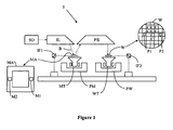
- Figure 1 depicts a lithographic apparatus according to an embodiment of the invention
- Figure 2 depicts the lithographic apparatus of Figure 1 in more detail
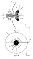
- Figure 3 depicts an embodiment of a radiation source of the lithographic apparatus of Figure 1 ;
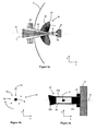
- Figures 4a and 4b depict an embodiment of a radiation source of the lithographic apparatus of Figure 1 ;
- Figures 5a-5d depict an embodiment of a radiation source of the lithographic apparatus of Figure 1 ;
- Figure 6 depicts an embodiment of a radiation source of the lithographic apparatus of Figure 1 .
- FIG. 1 schematically depicts a lithographic apparatus 1 according to an embodiment of the invention.
- the apparatus includes: an illumination system (illuminator) IL configured to condition a radiation beam B (e.g. extreme ultraviolet radiation); a support structure or support (e.g. a mask table) MT constructed to support a patterning device (e.g. a mask) MA and connected to a first positioner PM configured to accurately position the patterning device in accordance with certain parameters; a substrate table (e.g. a wafer table) WT constructed to hold a substrate (e.g. a resist-coated wafer) W and connected to a second positioner PW configured to accurately position the substrate in accordance with certain parameters; and a projection system (e.g. a refractive projection lens system) PS configured to project a pattern imparted to the radiation beam B by patterning device MA onto a target portion C (e.g. including one or more dies) of the substrate W.
- a radiation beam B e.g. extreme ultraviolet radiation
- the illumination system may include various types of optical components, such as refractive, reflective, magnetic, electromagnetic, electrostatic or other types of optical components, or any combination thereof, for directing, shaping, or controlling radiation.
- optical components such as refractive, reflective, magnetic, electromagnetic, electrostatic or other types of optical components, or any combination thereof, for directing, shaping, or controlling radiation.
- the support structure holds the patterning device in a manner that depends on the orientation of the patterning device, the design of the lithographic apparatus, and other conditions, such as for example whether or not the patterning device is held in a vacuum environment.
- the support structure can use mechanical, vacuum, electrostatic or other clamping techniques to hold the patterning device.
- the support structure may be a frame or a table, for example, which may be fixed or movable as required.
- the support structure may ensure that the patterning device is at a desired position, for example with respect to the projection system. Any use of the terms "reticle” or “mask” herein may be considered synonymous with the more general term "patterning device.”
- patterning device used herein should be broadly interpreted as referring to any device that can be used to impart a radiation beam with a pattern in its cross-section such as to create a pattern in a target portion of the substrate. It should be noted that the pattern imparted to the radiation beam may not exactly correspond to the desired pattern in the target portion of the substrate, for example if the pattern includes phase-shifting features or so called assist features. Generally, the pattern imparted to the radiation beam will correspond to a particular functional layer in a device being created in the target portion, such as an integrated circuit.
- the patterning device may be transmissive or reflective.
- Examples of patterning devices include masks, programmable mirror arrays, and programmable LCD panels.
- Masks are well known in lithography, and include mask types such as binary, alternating phase-shift, and attenuated phase-shift, as well as various hybrid mask types.
- An example of a programmable mirror array employs a matrix arrangement of small mirrors, each of which can be individually tilted so as to reflect an incoming radiation beam in different directions. The tilted mirrors impart a pattern in a radiation beam which is reflected by the mirror matrix.
- projection system used herein should be broadly interpreted as encompassing any type of projection system, including refractive, reflective, catadioptric, magnetic, electromagnetic and electrostatic optical systems, or any combination thereof, as appropriate for the exposure radiation being used, or for other factors such as the use of an immersion liquid or the use of a vacuum. Any use of the term “projection lens” herein may be considered as synonymous with the more general term “projection system”.
- the apparatus is of a reflective type (e.g. employing a reflective mask).
- the apparatus may be of a transmissive type (e.g. employing a transmissive mask).
- the lithographic apparatus may be of a type having two (dual stage) or more substrate tables (and/or two or more mask tables).
- the additional tables may be used in parallel, or preparatory steps may be carried out on one or more tables while one or more other tables are being used for exposure.
- the lithographic apparatus may also be of a type wherein at least a portion of the substrate may be covered by a liquid having a relatively high refractive index, e.g. water, so as to fill a space between the projection system and the substrate.
- a liquid having a relatively high refractive index e.g. water
- An immersion liquid may also be applied to other spaces in the lithographic apparatus, for example, between the mask and the projection system. Immersion techniques are well known in the art for increasing the numerical aperture of projection systems.
- immersion as used herein does not mean that a structure, such as a substrate, must be submerged in liquid, but rather only means that liquid is located between the projection system and the substrate during exposure.
- the illuminator IL receives a radiation beam from a radiation source SO.
- the source and the lithographic apparatus may be separate entities, for example when the source is an excimer laser. In such cases, the source is not considered to form part of the lithographic apparatus and the radiation beam is passed from the source SO to the illuminator IL with the aid of a beam delivery system including, for example, suitable directing mirrors and/or a beam expander. In other cases the source may be an integral part of the lithographic apparatus, for example when the source is a mercury lamp.
- the source SO and the illuminator IL, together with the beam delivery system if required, may be referred to as a radiation system.
- the illuminator IL may include an adjuster for adjusting the angular intensity distribution of the radiation beam. Generally, at least the outer and/or inner radial extent (commonly referred to as ⁇ -outer and ⁇ -inner, respectively) of the intensity distribution in a pupil plane of the illuminator can be adjusted.
- the illuminator IL may include various other components, such as an integrator and a condenser. The illuminator may be used to condition the radiation beam, to have a desired uniformity and intensity distribution in its cross-section.
- the radiation beam B is incident on the patterning device (e.g., mask MA), which is held on the support structure (e.g., mask table MT), and is patterned by the patterning device. After being reflected by the patterning device (e.g. mask) MA, the radiation beam B passes through the projection system PS, which focuses the beam onto a target portion C of the substrate W.
- the substrate table WT can be moved accurately, e.g. so as to position different target portions C in the path of the radiation beam B.
- the first positioner PM and another position sensor IF1 can be used to accurately position the patterning device (e.g.
- the support structure (e.g. mask table) MT may be realized with the aid of a long-stroke module (coarse positioning) and a short-stroke module (fine positioning), which form part of the first positioner PM.
- movement of the substrate table WT may be realized using a long-stroke module and a short-stroke module, which form part of the second positioner PW.
- the support structure (e.g. mask table) MT may be connected to a short-stroke actuator only, or may be fixed.
- Patterning device e.g.
- the mask alignment marks may be located between the dies.
- the depicted apparatus could be used in at least one of the following modes:
- step mode the support structure (e.g. mask table) MT and the substrate table WT are kept essentially stationary, while an entire pattern imparted to the radiation beam is projected onto a target portion C at one time (i.e. a single static exposure).
- the substrate table WT is then shifted in the X and/or Y direction so that a different target portion C can be exposed.
- the maximum size of the exposure field limits the size of the target portion C imaged in a single static exposure.
- the support structure (e.g. mask table) MT and the substrate table WT are scanned synchronously while a pattern imparted to the radiation beam is projected onto a target portion C (i.e. a single dynamic exposure).
- the velocity and direction of the substrate table WT relative to the support structure (e.g. mask table) MT may be determined by the (de-)magnification and image reversal characteristics of the projection system PS.
- the maximum size of the exposure field limits the width (in the non-scanning direction) of the target portion in a single dynamic exposure, whereas the length of the scanning motion determines the height (in the scanning direction) of the target portion.
- the support structure (e.g. mask table) MT is kept essentially stationary holding a programmable patterning device, and the substrate table WT is moved or scanned while a pattern imparted to the radiation beam is projected onto a target portion C.
- a pulsed radiation source is employed and the programmable patterning device is updated as required after each movement of the substrate table WT or in between successive radiation pulses during a scan.
- This mode of operation can be readily applied to maskless lithography that utilizes programmable patterning device, such as a programmable mirror array of a type as referred to above.
- Figure 2 shows the apparatus of Figure 1 in more detail, including the source SO, the illuminator IL, and the projection system PS.
- the source SO generates extreme ultraviolet (EUV) radiation from a plasma 2.
- EUV extreme ultraviolet
- the plasma 2 is created by directing a laser beam 3 onto droplets of a suitable material such as Sn or Gd which are generated by a droplet generator 4.
- a laser beam 3 causes the droplets to be vaporized, thereby generating the plasma 2.
- Radiation emitted by the plasma 2 is collected by a collector 5 to form an EUV radiation beam B.
- the EUV radiation beam B is directed onto a grating spectral filter 6.
- the EUV radiation beam then passes from the grating spectral filter 6 to an intermediate focus 7.
- the intermediate focus 7 acts as a virtual source point at an aperture in the source SO.
- the EUV radiation beam is reflected in the illuminator IL via first and second normal incidence reflectors 10, 11 onto a patterning device MA (e.g. a mask) positioned on support structure MT.
- a patterned EUV radiation beam 12 is formed which is imaged in the projection system PS via first and second reflective elements 13, 14 onto a substrate W held on a substrate table WT. More elements than shown may generally be present in the illuminator IL and projection system PS.
- a contamination barrier 20 which comprises plurality of rotating foils located at least partially between the collector 5 and the location at which the plasma 2 is formed.
- the contamination barrier is configured to reduce the amount of debris which is incident upon the collector 5 during operation of the source SO.
- Fuel droplets which are used by the source may for example be formed from tin (Sn).
- Different types of debris may be generated in the source.
- the first is slow atomic debris, such as thermalized atoms, i.e. with random direction and velocity according to the Maxwell distribution.
- the second is fast atomic debris, such as ions, neutrals and nanoclusters with a high ballistic velocity which may travel in the same direction as radiation generated by the plasma.
- the third type of debris is particles, which may include micrometer-sized ballistic particles which also travel in the same direction as radiation generated by the plasma. Particles may for example be generated when vaporization of the fuel droplets by the laser beam 3 is incomplete (e.g. if the fuel droplets are not mass limited).
- Droplets of fuel (not shown) are delivered to a plasma formation site 8 and are ignited by the laser beam 3 to form a plasma at the plasma formation site 8.
- the collector 5, which is a normal incidence collector, is configured to collect extreme ultraviolet radiation which is emitted by the plasma.
- the contamination barrier 20 is a rotating foil trap that includes a plurality of foils 21, a rotatable base 22, and a drive apparatus 23.
- the rotatable base 22 passes through an aperture in the collector 5 (the aperture may be provided in the center of the collector 5).
- the rotatable base 22 is hollow in order to allow the laser beam 3 to pass through the rotatable base 22.
- the drive apparatus 23 is desirably located behind the collector 5 so that it does not block any EUV radiation that is emitted by the plasma.
- the rotatable base 22 tapers towards the plasma formation site 8. As can be seen in Figure 3 , the tapering of the rotatable base 22 assists the rotatable base in accommodating the laser beam 3.
- the laser beam 3 is focused onto the plasma formation site 8, and as a consequence the diameter of the laser beam reduces significantly as it travels through the rotatable base 22.
- the tapering of the rotatable base 22 corresponds generally with the shape the laser beam 3 (although a gap 19 may exist between the inner surface of the rotatable base 22 and the laser beam 3).
- the rotatable base may have any suitable shape.
- the base may be in the form of a shaft that is cylindrical.
- tapering the rotatable base 22 reduces the proportion of EUV radiation which is blocked by the rotatable base, compared with the proportion of EUV radiation which would be blocked if the base were to be cylindrical.
- rotatable base is intended to include any suitable rotatable apparatus which may carry the foils. It is not intended to be limited to for example a cylindrical, frustoconical or conical shape.
- the foils 21 may be made for example from a refractory metal, an alloy of a refractory metal, or a superalloy based on for example nickel, nickel-iron or cobalt.
- the foils may be made from a material which has high mechanical strength and creep resistance at high temperature
- the drive apparatus 23 drives the rotatable base 22 to rotate about a rotation axis A, thereby rotating the foils 21.
- This rotation of the foils 21 allows them to intercept debris particles, thereby preventing those intercepted debris particles from the reaching the collector 5.
- the debris particles are projected from the foils centrifugally in a direction perpendicular to the rotation axis A. The interception and subsequent ejection of the debris particles by the foils 21 reduces the rate at which debris accumulates on the collector 5, thereby extending the intervals between replacement or cleaning of the collector (i.e. allowing the lithographic apparatus to operate for longer).
- the rotation axis A of the rotatable base 22 may correspond with the path of the laser beam 3.
- the rotation axis A of the rotatable base 22 may also correspond with the optical axis of the lithography system.
- the ability of the contamination barrier 20 to suppress debris particles may be expressed in terms of a "stopping speed", i.e. the maximum speed of debris particles that are fully intercepted by the foils 21.
- An example of a radial path L is shown in Figure 3 .
- the shape of the foils 21 may be such that a minimum length L , and hence a corresponding minimum stopping speed v, is attained over the entire collection angle (i.e. over all angles from which the collector 5 receives EUV radiation and debris from the plasma).
- the foils 21 may be shaped such that the foils are longer at their base (measuring in a direction parallel to the optical axis) than at a point midway between their base and their distal end.
- the foils 21 may be shaped such that the foils are longer at their base (measuring in a radial direction from the plasma formation site 8) than at a point midway between their base and their distal end.
- the foils 21 have a distal end 24 which is positioned such that droplets radially emitted from this distal end do not hit the collector 5.
- the foils 21 may narrow to a point, such that the distal end 24 is pointed.
- the foils may include a curved tip (not illustrated) at the distal end.
- the foils 21 of the contamination barrier 20 are positioned (e.g. the foils are constructed and arranged) such that droplets radially emitted from any point on the foils do not hit the collector 5.
- the foils may be constructed and arranged such that there is no overlap in the radial direction (i.e. transverse to the optical axis A) between the foils and the collector. This may be achieved for example by making the foils 21 shorter in the direction of the optical axis and/or moving the foils 21 closer to the plasma formation site 8.
- Figures 4a and 4b show an embodiment of the invention which may improve the mechanical stability of the contamination barrier 20 (reference numerals used in Figures 4a and 4b correspond with those used in Figure 3 where appropriate).
- Figure 4a shows the contamination barrier 20 as viewed from the side in cross-section
- Figure 4b shows the contamination barrier as viewed from the front (i.e. as seen from the plasma formation site 8).
- the rotatable base 22 of the contamination barrier 20 is supported by a support 26 which is provided on a side of the plasma formation site 8 that is closest to the collector 5.
- the support 26 extends across the collector, between the collector and the plasma formation site 8.
- the support extends from walls (not shown) of the source or to some other structure.
- the support 26 may be constructed and arranged to generally obscure only a small part of the collection angle of the collector 5, so as to limit the amount of EUV radiation which is blocked by the support 26.
- the support 26 may be aligned with some other existing apparatus which also blocks radiation, such as for example a laser beam stop (not shown in Figure 4a ). This may allow the support 26 to be provided without the support reducing the amount of EUV radiation which is collected by the collector 5 and focused at the intermediate focus 7.
- the support 26 is shown as extending from the rotatable base 22 in two directions, it may for example extend in only one direction (or any other number of directions).
- An annular bearing 25 may be provided between the support 26 and the rotatable base 22.
- the annular bearing 25 may for example be a ball bearing or a liquid metal bearing.
- the rotatable base 22 may extend beyond the plasma formation site 8 in order to improve the mechanical stability of the contamination barrier 20.
- This embodiment is shown in Figures 5a-5c (reference numerals used in Figures 5a-5c correspond with those used in Figures 3 , 4a and 4b where appropriate).
- Figure 5a shows the contamination barrier in cross-section.
- the rotatable base 22 extends past the plasma formation site 8 and is supported by a support 27 at a location which is beyond the plasma formation site relative to the collector.
- the support 27 may for example be a beam dump which is arranged to receive the laser beam 3.
- An annular bearing 28 may be provided between the rotatable base 22 and the support 27.
- the annular bearing 28 may for example be a ball bearing or a liquid metal bearing.
- FIG. 5b shows a cross-section along axis A at the plasma formation site 8
- Figure 5c shows part of the rotatable base 22 viewed from the side.
- the rotatable base 22 comprises four struts 22a which are equally distributed about the axis of rotation.
- the four struts are connected at one end to an outwardly tapering part 22b of the rotatable base 22 (only some of the outwardly tapering part is shown), and are connected at an opposite end to a cylindrical part 22c of the rotatable base.
- the cylindrical part 22c of the rotatable base is received by the annular bearing 28 and the support 27.
- Openings 29 between the struts 22a allow the majority of EUV radiation which is emitted from the plasma formation site 8 to pass out of the rotatable base 22 and towards the collector 5.
- the openings 29 also allow fuel droplets 30 to travel to the plasma formation site 8.
- Projection of fuel droplets 30 towards the plasma formation site 8 by the droplet generator 4 may be synchronized with rotation of the rotatable base 22, such that the fuel droplets pass through openings 29 to the plasma formation site 8 and do not hit the struts 22a.
- the laser beam 3 may be synchronized with rotation of the rotatable base 22, such that when one of the struts 22a blocks a fuel droplet from reaching the plasma formation site 8, the laser is not incident on the plasma formation site. This may be achieved for example by not firing the laser, or by blocking the laser beam 3 before it enters the source.
- any suitable number of struts may be used.
- the number of struts may be 2, 3, 4, 5, etc.
- Increasing the number of struts may increase the mechanical stability of the contamination barrier, but may block more EUV radiation.
- the struts 22a and cylindrical portion 22c of the rotatable base 22 shown in Figure 5a-c are arranged to rotate.
- struts 31 and a cylindrical portion 32 are fixed to the support 27 and do not rotate.
- the cylindrical portion 32 is fixed to the support 27 by any suitable means, such as for example welding or using one or more bolts.
- the struts 31 are fixed to the support 27 by any suitable means.
- the struts 31 and cylindrical portion 32 may be formed from a single piece of material.
- the support 27, cylindrical portion 32 and struts 31 may be formed from a single piece of material.
- the cylindrical portion 32 is mentioned as an example, and is need not necessarily be cylindrical (it may be any suitable shape).
- the struts 31 may be connected directly to the support 27 (i.e. without the cylindrical portion being present).
- the rotatable base 22 is connected to the struts 31, for example via bearings 28a. This provides the rotatable base 22 with support, while allowing it to rotate.
- a potential advantage of the arrangement shown in Figure 5d is that spaces 29 between the struts 31 do not move, providing a permanently clear path for fuel droplets to travel to the plasma formation site 8.
- foils 21 a of the contamination barrier 20 extend past the plasma formation site 8 (i.e. extend to a location which is beyond the plasma formation site relative to the collector 5).
- the foils are connected to a cylindrical portion 22c of the rotatable base 22.
- the cylindrical portion 22c of the rotatable base is supported by the support 27.
- An annular bearing 28 is provided between the cylindrical portion 22c of the rotatable base 22 and the support 27.
- the portion of the rotatable base which passes over the plasma formation site 8 is formed from the foils themselves 21 a rather than from struts.
- foils may stop short of the plasma formation site 8, for example having a construction as described above in relation to Figures 3-5d .
- four of the foils 21 a may pass over the plasma formation site 8 and be connected to the support 27 (e.g. for example via the cylindrical part 22c of the rotatable base), with the remaining foils stopping short of the plasma formation site.
- 2, 3, 5, 6, etc foils may be connected to the support 27, with the remaining foils for example stopping short of the plasma formation site 8.
- Those foils 21a which are connected to the support 27 may be thicker than the foils which stop short of the plasma formation site 8. In other words, those foils which have a mechanical function may be thicker than those foils whose only function is to intercept debris.
- the foils 21 a that are connected to the support 27 may act both to provide a mechanical connection to the support, and to intercept debris.
- An innermost edge of those foils 21 a which are connected to the support 27 may curve around the plasma formation site 8, the curve keeping the innermost edge of the foils further away from the plasma formation site than would otherwise be the case (i.e. if the curve were not present).
- the curve may for example be shaped such that no portion of the foils 21 a comes closer than a predetermined distance to the plasma formation site 8.
- the curve may be shaped such that no portion of the foils 21 a comes closer than 3 cm (or some other suitable distance) to the plasma formation site 8.
- a cooling system (not shown) may be provided in the drive apparatus 23.
- the cooling system may help to keep the foils 21, 21 a cool.
- the cooling system may be any suitable cooling system, and may provide active cooling.
- a cooling system may be provided at the support 27.
- the cooling system may help to keep the foils 21, 21a cool, and may help to keep the struts 22a cool.
- the cooling system may be any suitable cooling system, and may provide active cooling.
- the cooling system may provide cooling via the annular bearings 28, which may for example be liquid metal bearings.
- a cooling system may be provided in the non-rotating part 26; 31. This may assist in cooling the foils 21 of the contamination barrier, since cooling is provided close to the foils.
- the cooling system may provide cooling via the annular bearings 28, which may for example be liquid metal bearings.
- ignition of the fuel droplets 30 has been described as being achieved using a laser beam 3.
- a radiation beam which is generated by a source other than a laser may be used.
- Embodiments of the present invention provide an LPP source with a coaxial arrangement of the rotating foil trap and the laser beam, wherein the rotatable base of the rotating foil trap is hollow in order to let the laser beam pass through.
- This arrangement may have the following advantages: (i) both the plasma formation and the foil trap transmission are rotationally symmetric about the optical axis; (ii) the amount of collectable EUV radiation is not substantially affected; and (iii) particles that are re-emitted by the rotating foil trap are deposited outside the collector.
- Embodiments of the invention may reduce the rate at which debris accumulates on the collector of the lithographic apparatus, thereby extending the intervals between cleaning or replacement of the collector. This may be expressed as saying that embodiments of the invention may extend the lifetime of the collector.
- DPP discharge-produced plasma
- the rotating foil trap is placed between the source and the grazing-incidence collector, with the rotatable base coinciding with the optical axis.
- the optical axis of the DPP source provides a natural location for the rotatable base of the rotating foil trap, since the amount of EUV which is collected along the optical axis is not substantial.
- the prior art does not teach or suggest providing a rotating foil trap in a LPP source. Furthermore, there is no natural location in which to provide the rotatable base. The invention therefore provides an inventive step when compared with the prior art.
- lithographic apparatus in the manufacture of ICs
- the lithographic apparatus described herein may have other applications, such as the manufacture of integrated optical systems, guidance and detection patterns for magnetic domain memories, flat-panel displays, liquid-crystal displays (LCDs), thin-film magnetic heads, etc.
- LCDs liquid-crystal displays
- any use of the terms “wafer” or “die” herein may be considered as synonymous with the more general terms “substrate” or "target portion”, respectively.
- the substrate referred to herein may be processed, before or after exposure, in for example a track (a tool that typically applies a layer of resist to a substrate and develops the exposed resist), a metrology tool and/or an inspection tool. Where applicable, the disclosure herein may be applied to such and other substrate processing tools. Further, the substrate may be processed more than once, for example in order to create a multi-layer IC, so that the term substrate used herein may also refer to a substrate that already contains multiple processed layers.
- EUV radiation as used above may be interpreted as meaning electromagnetic radiation having a wavelength of less than 20 nm, for example within the range of 10-20 nm, for example within the range of 13-14, for example within the range of 5-10 nm, for example such as 6.7 nm or 6.8 nm.
- lens may refer to any one or combination of various types of optical components, including refractive, reflective, magnetic, electromagnetic and electrostatic optical components.
Claims (15)
- Eine Strahlungsquelle (SO), die konfiguriert ist, um extrem ultraviolette Strahlung zu erzeugen, wobei die Strahlungsquelle (SO) Folgendes beinhaltet:eine Plasmaformungsstelle (8), die sich in einer Position befindet, in der ein Brennstoff mit einem Strahl aus Strahlung (3) in Kontakt gebracht wird, um ein Plasma (2) zu formen;einen Kollektor (5), der konstruiert und eingerichtet ist, um extrem ultraviolette Strahlung, die an der Plasmaformungsstelle (8) geformt wird, zu sammeln und dadurch einen extrem ultravioletten Strahlungsstrahl zu formen; undeine Kontaminationssperre (20), die eine Vielzahl von Folien (21), welche sich mindestens teilweise zwischen der Plasmaformungsstelle (8) und dem Kollektor (5) befinden, und eine drehbare Basis (22), die eine Drehachse (A) aufweist und operativ mit der Vielzahl von Folien (21) verbunden ist, beinhaltet, dadurch gekennzeichnet, dass die drehbare Basis (22) eine Öffnung aufweist, um zu ermöglichen, dass der Strahl aus Strahlung (3) durch die Kontaminationssperre (20) zu der Plasmaformungsstelle (8) geht.
- Strahlungsquelle gemäß Anspruch 1, wobei der Kollektor (5) einen Durchlass beinhaltet und sich die drehbare Basis (22) der Kontaminationssperre (20) durch den Durchlass erstreckt.
- Strahlungsquelle gemäß Anspruch 1, wobei der Strahl aus Strahlung (3) durch einen Laser bereitgestellt wird, der sich entfernt von dem Kollektor (5) befindet.
- Strahlungsquelle gemäß Anspruch 1, wobei die Kontaminationssperre (20) ferner ein Antriebsgerät (23) beinhaltet, das sich in Bezug auf die Plasmaformungsstelle (8) hinter dem Kollektor (5) befindet, wobei das Antriebsgerät (23) konfiguriert ist, um die drehbare Basis (22) um die Drehachse (A) anzutreiben und dadurch die Folien (21) anzutreiben.
- Strahlungsquelle gemäß Anspruch 1, wobei die Vielzahl von Folien (21) so konstruiert und eingerichtet sind, dass es in der radialen Richtung zwischen der Vielzahl von Folien (21) und dem Kollektor (5) kein Überlappen gibt, wobei die radiale Richtung die zu der Drehachse (A) senkrechte Richtung ist.
- Strahlungsquelle gemäß Anspruch 1, wobei die Vielzahl von Folien (21) so konstruiert und eingerichtet sind, dass an der Plasmaformungsstelle (8) erzeugte Trümmerteilchen, die von der Vielzahl von Folien (21) abgefangen werden und die während der Verwendung radial emittiert werden, den Kollektor (5) nicht treffen, wobei die radiale Richtung die zu der Drehachse (A) senkrechte Richtung ist.
- Strahlungsquelle gemäß Anspruch 6, wobei die Vielzahl von Folien (21) distale Enden (24) aufweisen, die so positioniert sind, dass die während der Verwendung radial von den distalen Enden (24) emittierten Trümmerteilchen den Kollektor (5) nicht treffen.
- Strahlungsquelle gemäß Anspruch 1, wobei die Kontaminationssperre (20) ferner eine Stütze (26, 27) beinhaltet, die konstruiert und eingerichtet ist, um ein Ende der drehbaren Basis (22) zu stützen.
- Strahlungsquelle gemäß Anspruch 8, wobei sich die Stütze (26) zwischen dem Kollektor (5) und der Plasmaformungsstelle (8) über den Kollektor (5) erstreckt.
- Strahlungsquelle gemäß Anspruch 1, wobei sich die drehbare Basis (22) über die Plasmaformungsstelle (8) hinaus in einer von dem Kollektor (5) weg weisenden Richtung erstreckt.
- Strahlungsquelle gemäß Anspruch 10, wobei die drehbare Basis (22) von einem Strahlfänger gestützt wird.
- Strahlungsquelle gemäß Anspruch 10, wobei die drehbare Basis (22) in der Nähe der Plasmaformungsstelle (8) eine Vielzahl von Streben (22a) beinhaltet.
- Strahlungsquelle gemäß Anspruch 12, die ferner einen Tröpfchengenerator (4) beinhaltet, der konstruiert und eingerichtet ist, um Tröpfchen des Brennstoffs an die Plasmaformungsstelle (8) zu liefern, wobei der Tröpfchengenerator (4) mit der Drehung der Kontaminationssperre (20) synchronisiert ist, so dass keine Tröpfchen erzeugt werden, wenn ein Tröpfchen eine der Streben (22a) treffen würde.
- Ein lithographisches Gerät, das eine Strahlungsquelle gemäß einem der vorhergehenden Ansprüche beinhaltet.
- Ein Verfahren zum Erzeugen von extrem ultravioletter Strahlung, wobei das Verfahren Folgendes beinhaltet:In-Kontakt-Bringen von Brennstoff mit einem Strahl aus Strahlung (3), um ein Plasma (2) zu formen;Verwenden eines Kollektors (5), um extrem ultraviolette Strahlung, die von dem Plasma (2) geformt wird, zu sammeln und dadurch einen extrem ultravioletten Strahlungsstrahl (8) zu formen; undDrehen einer Vielzahl von Folien (21) auf einer drehbaren Basis (22), wobei sich die Folien (21) mindestens teilweise zwischen dem Plasma (2) und dem Kollektor (5) befinden, so dass Trümmerteilchen von den Folien (21) abgefangen werden;wobei der Strahl aus Strahlung (3) durch die drehbare Basis (22) geführt wird, bevor er mit dem Brennstoff in Kontakt kommt, um das Plasma (2) zu formen.
Applications Claiming Priority (5)
| Application Number | Priority Date | Filing Date | Title |
|---|---|---|---|
| US7144108P | 2008-04-29 | 2008-04-29 | |
| US13613108P | 2008-08-14 | 2008-08-14 | |
| US13630408P | 2008-08-26 | 2008-08-26 | |
| US13651908P | 2008-09-11 | 2008-09-11 | |
| US19351108P | 2008-12-04 | 2008-12-04 |
Publications (2)
| Publication Number | Publication Date |
|---|---|
| EP2113813A1 EP2113813A1 (de) | 2009-11-04 |
| EP2113813B1 true EP2113813B1 (de) | 2012-06-27 |
Family
ID=40732117
Family Applications (1)
| Application Number | Title | Priority Date | Filing Date |
|---|---|---|---|
| EP09005144A Not-in-force EP2113813B1 (de) | 2008-04-29 | 2009-04-08 | Strahlungsquelle und lithografische Vorrichtung |
Country Status (3)
| Country | Link |
|---|---|
| US (1) | US7952084B2 (de) |
| EP (1) | EP2113813B1 (de) |
| JP (1) | JP4907690B2 (de) |
Families Citing this family (6)
| Publication number | Priority date | Publication date | Assignee | Title |
|---|---|---|---|---|
| JP5559562B2 (ja) * | 2009-02-12 | 2014-07-23 | ギガフォトン株式会社 | 極端紫外光光源装置 |
| CN102170086B (zh) * | 2011-03-15 | 2012-07-11 | 中国工程物理研究院流体物理研究所 | 激光辐照实心锥靶产生x射线的装置 |
| WO2014095262A1 (en) * | 2012-12-21 | 2014-06-26 | Asml Netherlands B.V. | Beam delivery for euv lithography |
| JP6135410B2 (ja) * | 2013-09-06 | 2017-05-31 | ウシオ電機株式会社 | ホイルトラップ及びこのホイルトラップを用いた光源装置 |
| NL2013493A (en) | 2013-10-16 | 2015-04-20 | Asml Netherlands Bv | Radiation source, lithographic apparatus device manufacturing method, sensor system and sensing method. |
| CN111577562B (zh) * | 2020-05-22 | 2021-03-02 | 中国科学院微小卫星创新研究院 | 多孔发射针浸润装置及方法 |
Family Cites Families (10)
| Publication number | Priority date | Publication date | Assignee | Title |
|---|---|---|---|---|
| US1912951A (en) | 1931-01-05 | 1933-06-06 | Williams Co | Steel wool machine |
| US6815700B2 (en) * | 1997-05-12 | 2004-11-09 | Cymer, Inc. | Plasma focus light source with improved pulse power system |
| JP2003022950A (ja) * | 2001-07-05 | 2003-01-24 | Canon Inc | X線光源用デブリ除去装置及び、デブリ除去装置を用いた露光装置 |
| CN100476585C (zh) * | 2002-12-23 | 2009-04-08 | Asml荷兰有限公司 | 具有可扩展薄片的杂质屏蔽 |
| US7217940B2 (en) * | 2003-04-08 | 2007-05-15 | Cymer, Inc. | Collector for EUV light source |
| JP4458330B2 (ja) * | 2003-12-26 | 2010-04-28 | キヤノン株式会社 | 光源ユニットの多層膜ミラーを交換する方法 |
| US7164144B2 (en) | 2004-03-10 | 2007-01-16 | Cymer Inc. | EUV light source |
| US7109503B1 (en) | 2005-02-25 | 2006-09-19 | Cymer, Inc. | Systems for protecting internal components of an EUV light source from plasma-generated debris |
| JP4850558B2 (ja) * | 2006-03-31 | 2012-01-11 | キヤノン株式会社 | 光源装置、及びそれを用いた露光装置、デバイス製造方法 |
| US7442948B2 (en) * | 2006-05-15 | 2008-10-28 | Asml Netherlands B.V. | Contamination barrier and lithographic apparatus |
-
2009
- 2009-04-08 EP EP09005144A patent/EP2113813B1/de not_active Not-in-force
- 2009-04-22 JP JP2009103512A patent/JP4907690B2/ja not_active Expired - Fee Related
- 2009-04-28 US US12/431,367 patent/US7952084B2/en not_active Expired - Fee Related
Also Published As
| Publication number | Publication date |
|---|---|
| US7952084B2 (en) | 2011-05-31 |
| JP2009267408A (ja) | 2009-11-12 |
| EP2113813A1 (de) | 2009-11-04 |
| US20090272916A1 (en) | 2009-11-05 |
| JP4907690B2 (ja) | 2012-04-04 |
Similar Documents
| Publication | Publication Date | Title |
|---|---|---|
| EP2321704B1 (de) | Strahlungsquelle und lithografischer apparat | |
| EP2170021B1 (de) | Quellenmodul, Strahlungsquelle und Lithografievorrichtung | |
| EP2154574B1 (de) | Strahlungsquelle und Verfahren zur Strahlungserzeugung | |
| JP5162546B2 (ja) | 放射源及びリソグラフィ装置 | |
| EP1793277B1 (de) | Strahlungssystem und lithografische Vorrichtung | |
| JP6291477B2 (ja) | リソグラフィ装置用の汚染トラップ | |
| EP2113813B1 (de) | Strahlungsquelle und lithografische Vorrichtung | |
| JP2010062560A5 (de) | ||
| JP2012506133A (ja) | コレクタアセンブリ、放射源、リソグラフィ装置およびデバイス製造方法 | |
| US20110242516A1 (en) | Lithographic Apparatus, a Radiation System, a Device Manufacturing Method and a Radiation Generating Method | |
| US10678140B2 (en) | Suppression filter, radiation collector and radiation source for a lithographic apparatus; method of determining a separation distance between at least two reflective surface levels of a suppression filter | |
| US20140253894A1 (en) | Radiation Source | |
| JP5531053B2 (ja) | 放射源、リソグラフィ装置及びデバイス製造方法 | |
| JP5973567B2 (ja) | 放射源、放射システム、リソグラフィ装置、および燃料液滴を捕集する方法 | |
| JP6395832B2 (ja) | 放射源用コンポーネント、関連した放射源およびリソグラフィ装置 | |
| NL2008963A (en) | Ion capture apparatus, laser produced plasma radiation source, lithographic apparatus. | |
| NL2005763A (en) | Lithographic apparatus. | |
| NL2011772A (en) | Beam delivery apparatus, euv radiation apparatus, euv optical apparatus, lithographic apparatus and associated methods. | |
| NL2011762A (en) | Beam delivery apparatus for lithographic apparatus, euv radiation system and associated method. |
Legal Events
| Date | Code | Title | Description |
|---|---|---|---|
| PUAI | Public reference made under article 153(3) epc to a published international application that has entered the european phase |
Free format text: ORIGINAL CODE: 0009012 |
|
| AK | Designated contracting states |
Kind code of ref document: A1 Designated state(s): AT BE BG CH CY CZ DE DK EE ES FI FR GB GR HR HU IE IS IT LI LT LU LV MC MK MT NL NO PL PT RO SE SI SK TR |
|
| 17P | Request for examination filed |
Effective date: 20091117 |
|
| 17Q | First examination report despatched |
Effective date: 20091208 |
|
| GRAP | Despatch of communication of intention to grant a patent |
Free format text: ORIGINAL CODE: EPIDOSNIGR1 |
|
| GRAS | Grant fee paid |
Free format text: ORIGINAL CODE: EPIDOSNIGR3 |
|
| GRAA | (expected) grant |
Free format text: ORIGINAL CODE: 0009210 |
|
| AK | Designated contracting states |
Kind code of ref document: B1 Designated state(s): AT BE BG CH CY CZ DE DK EE ES FI FR GB GR HR HU IE IS IT LI LT LU LV MC MK MT NL NO PL PT RO SE SI SK TR |
|
| REG | Reference to a national code |
Ref country code: GB Ref legal event code: FG4D |
|
| REG | Reference to a national code |
Ref country code: CH Ref legal event code: EP |
|
| REG | Reference to a national code |
Ref country code: AT Ref legal event code: REF Ref document number: 564522 Country of ref document: AT Kind code of ref document: T Effective date: 20120715 |
|
| REG | Reference to a national code |
Ref country code: IE Ref legal event code: FG4D |
|
| REG | Reference to a national code |
Ref country code: DE Ref legal event code: R096 Ref document number: 602009007815 Country of ref document: DE Effective date: 20120823 |
|
| PG25 | Lapsed in a contracting state [announced via postgrant information from national office to epo] |
Ref country code: SE Free format text: LAPSE BECAUSE OF FAILURE TO SUBMIT A TRANSLATION OF THE DESCRIPTION OR TO PAY THE FEE WITHIN THE PRESCRIBED TIME-LIMIT Effective date: 20120627 Ref country code: NO Free format text: LAPSE BECAUSE OF FAILURE TO SUBMIT A TRANSLATION OF THE DESCRIPTION OR TO PAY THE FEE WITHIN THE PRESCRIBED TIME-LIMIT Effective date: 20120927 Ref country code: FI Free format text: LAPSE BECAUSE OF FAILURE TO SUBMIT A TRANSLATION OF THE DESCRIPTION OR TO PAY THE FEE WITHIN THE PRESCRIBED TIME-LIMIT Effective date: 20120627 Ref country code: LT Free format text: LAPSE BECAUSE OF FAILURE TO SUBMIT A TRANSLATION OF THE DESCRIPTION OR TO PAY THE FEE WITHIN THE PRESCRIBED TIME-LIMIT Effective date: 20120627 |
|
| REG | Reference to a national code |
Ref country code: NL Ref legal event code: VDEP Effective date: 20120627 |
|
| REG | Reference to a national code |
Ref country code: AT Ref legal event code: MK05 Ref document number: 564522 Country of ref document: AT Kind code of ref document: T Effective date: 20120627 |
|
| REG | Reference to a national code |
Ref country code: LT Ref legal event code: MG4D Effective date: 20120627 |
|
| PG25 | Lapsed in a contracting state [announced via postgrant information from national office to epo] |
Ref country code: GR Free format text: LAPSE BECAUSE OF FAILURE TO SUBMIT A TRANSLATION OF THE DESCRIPTION OR TO PAY THE FEE WITHIN THE PRESCRIBED TIME-LIMIT Effective date: 20120928 Ref country code: HR Free format text: LAPSE BECAUSE OF FAILURE TO SUBMIT A TRANSLATION OF THE DESCRIPTION OR TO PAY THE FEE WITHIN THE PRESCRIBED TIME-LIMIT Effective date: 20120627 Ref country code: SI Free format text: LAPSE BECAUSE OF FAILURE TO SUBMIT A TRANSLATION OF THE DESCRIPTION OR TO PAY THE FEE WITHIN THE PRESCRIBED TIME-LIMIT Effective date: 20120627 Ref country code: LV Free format text: LAPSE BECAUSE OF FAILURE TO SUBMIT A TRANSLATION OF THE DESCRIPTION OR TO PAY THE FEE WITHIN THE PRESCRIBED TIME-LIMIT Effective date: 20120627 |
|
| PG25 | Lapsed in a contracting state [announced via postgrant information from national office to epo] |
Ref country code: CY Free format text: LAPSE BECAUSE OF FAILURE TO SUBMIT A TRANSLATION OF THE DESCRIPTION OR TO PAY THE FEE WITHIN THE PRESCRIBED TIME-LIMIT Effective date: 20120627 Ref country code: CZ Free format text: LAPSE BECAUSE OF FAILURE TO SUBMIT A TRANSLATION OF THE DESCRIPTION OR TO PAY THE FEE WITHIN THE PRESCRIBED TIME-LIMIT Effective date: 20120627 Ref country code: IS Free format text: LAPSE BECAUSE OF FAILURE TO SUBMIT A TRANSLATION OF THE DESCRIPTION OR TO PAY THE FEE WITHIN THE PRESCRIBED TIME-LIMIT Effective date: 20121027 Ref country code: EE Free format text: LAPSE BECAUSE OF FAILURE TO SUBMIT A TRANSLATION OF THE DESCRIPTION OR TO PAY THE FEE WITHIN THE PRESCRIBED TIME-LIMIT Effective date: 20120627 Ref country code: RO Free format text: LAPSE BECAUSE OF FAILURE TO SUBMIT A TRANSLATION OF THE DESCRIPTION OR TO PAY THE FEE WITHIN THE PRESCRIBED TIME-LIMIT Effective date: 20120627 Ref country code: BE Free format text: LAPSE BECAUSE OF FAILURE TO SUBMIT A TRANSLATION OF THE DESCRIPTION OR TO PAY THE FEE WITHIN THE PRESCRIBED TIME-LIMIT Effective date: 20120627 Ref country code: AT Free format text: LAPSE BECAUSE OF FAILURE TO SUBMIT A TRANSLATION OF THE DESCRIPTION OR TO PAY THE FEE WITHIN THE PRESCRIBED TIME-LIMIT Effective date: 20120627 Ref country code: SK Free format text: LAPSE BECAUSE OF FAILURE TO SUBMIT A TRANSLATION OF THE DESCRIPTION OR TO PAY THE FEE WITHIN THE PRESCRIBED TIME-LIMIT Effective date: 20120627 |
|
| PG25 | Lapsed in a contracting state [announced via postgrant information from national office to epo] |
Ref country code: PL Free format text: LAPSE BECAUSE OF FAILURE TO SUBMIT A TRANSLATION OF THE DESCRIPTION OR TO PAY THE FEE WITHIN THE PRESCRIBED TIME-LIMIT Effective date: 20120627 Ref country code: IT Free format text: LAPSE BECAUSE OF FAILURE TO SUBMIT A TRANSLATION OF THE DESCRIPTION OR TO PAY THE FEE WITHIN THE PRESCRIBED TIME-LIMIT Effective date: 20120627 Ref country code: PT Free format text: LAPSE BECAUSE OF FAILURE TO SUBMIT A TRANSLATION OF THE DESCRIPTION OR TO PAY THE FEE WITHIN THE PRESCRIBED TIME-LIMIT Effective date: 20121029 |
|
| PG25 | Lapsed in a contracting state [announced via postgrant information from national office to epo] |
Ref country code: NL Free format text: LAPSE BECAUSE OF FAILURE TO SUBMIT A TRANSLATION OF THE DESCRIPTION OR TO PAY THE FEE WITHIN THE PRESCRIBED TIME-LIMIT Effective date: 20120627 |
|
| PG25 | Lapsed in a contracting state [announced via postgrant information from national office to epo] |
Ref country code: ES Free format text: LAPSE BECAUSE OF FAILURE TO SUBMIT A TRANSLATION OF THE DESCRIPTION OR TO PAY THE FEE WITHIN THE PRESCRIBED TIME-LIMIT Effective date: 20121008 Ref country code: DK Free format text: LAPSE BECAUSE OF FAILURE TO SUBMIT A TRANSLATION OF THE DESCRIPTION OR TO PAY THE FEE WITHIN THE PRESCRIBED TIME-LIMIT Effective date: 20120627 |
|
| PLBE | No opposition filed within time limit |
Free format text: ORIGINAL CODE: 0009261 |
|
| STAA | Information on the status of an ep patent application or granted ep patent |
Free format text: STATUS: NO OPPOSITION FILED WITHIN TIME LIMIT |
|
| 26N | No opposition filed |
Effective date: 20130328 |
|
| REG | Reference to a national code |
Ref country code: DE Ref legal event code: R097 Ref document number: 602009007815 Country of ref document: DE Effective date: 20130328 |
|
| PG25 | Lapsed in a contracting state [announced via postgrant information from national office to epo] |
Ref country code: BG Free format text: LAPSE BECAUSE OF FAILURE TO SUBMIT A TRANSLATION OF THE DESCRIPTION OR TO PAY THE FEE WITHIN THE PRESCRIBED TIME-LIMIT Effective date: 20120927 |
|
| PG25 | Lapsed in a contracting state [announced via postgrant information from national office to epo] |
Ref country code: MC Free format text: LAPSE BECAUSE OF FAILURE TO SUBMIT A TRANSLATION OF THE DESCRIPTION OR TO PAY THE FEE WITHIN THE PRESCRIBED TIME-LIMIT Effective date: 20120627 |
|
| REG | Reference to a national code |
Ref country code: CH Ref legal event code: PL |
|
| GBPC | Gb: european patent ceased through non-payment of renewal fee |
Effective date: 20130408 |
|
| REG | Reference to a national code |
Ref country code: IE Ref legal event code: MM4A |
|
| PG25 | Lapsed in a contracting state [announced via postgrant information from national office to epo] |
Ref country code: LI Free format text: LAPSE BECAUSE OF NON-PAYMENT OF DUE FEES Effective date: 20130430 Ref country code: GB Free format text: LAPSE BECAUSE OF NON-PAYMENT OF DUE FEES Effective date: 20130408 Ref country code: CH Free format text: LAPSE BECAUSE OF NON-PAYMENT OF DUE FEES Effective date: 20130430 |
|
| PG25 | Lapsed in a contracting state [announced via postgrant information from national office to epo] |
Ref country code: IE Free format text: LAPSE BECAUSE OF NON-PAYMENT OF DUE FEES Effective date: 20130408 |
|
| PG25 | Lapsed in a contracting state [announced via postgrant information from national office to epo] |
Ref country code: MT Free format text: LAPSE BECAUSE OF FAILURE TO SUBMIT A TRANSLATION OF THE DESCRIPTION OR TO PAY THE FEE WITHIN THE PRESCRIBED TIME-LIMIT Effective date: 20120627 |
|
| PG25 | Lapsed in a contracting state [announced via postgrant information from national office to epo] |
Ref country code: TR Free format text: LAPSE BECAUSE OF FAILURE TO SUBMIT A TRANSLATION OF THE DESCRIPTION OR TO PAY THE FEE WITHIN THE PRESCRIBED TIME-LIMIT Effective date: 20120627 |
|
| PG25 | Lapsed in a contracting state [announced via postgrant information from national office to epo] |
Ref country code: LU Free format text: LAPSE BECAUSE OF NON-PAYMENT OF DUE FEES Effective date: 20130408 Ref country code: HU Free format text: LAPSE BECAUSE OF FAILURE TO SUBMIT A TRANSLATION OF THE DESCRIPTION OR TO PAY THE FEE WITHIN THE PRESCRIBED TIME-LIMIT; INVALID AB INITIO Effective date: 20090408 Ref country code: MK Free format text: LAPSE BECAUSE OF FAILURE TO SUBMIT A TRANSLATION OF THE DESCRIPTION OR TO PAY THE FEE WITHIN THE PRESCRIBED TIME-LIMIT Effective date: 20120627 |
|
| REG | Reference to a national code |
Ref country code: FR Ref legal event code: PLFP Year of fee payment: 8 |
|
| REG | Reference to a national code |
Ref country code: FR Ref legal event code: PLFP Year of fee payment: 9 |
|
| PGFP | Annual fee paid to national office [announced via postgrant information from national office to epo] |
Ref country code: DE Payment date: 20170419 Year of fee payment: 9 Ref country code: FR Payment date: 20170419 Year of fee payment: 9 |
|
| REG | Reference to a national code |
Ref country code: DE Ref legal event code: R119 Ref document number: 602009007815 Country of ref document: DE |
|
| PG25 | Lapsed in a contracting state [announced via postgrant information from national office to epo] |
Ref country code: DE Free format text: LAPSE BECAUSE OF NON-PAYMENT OF DUE FEES Effective date: 20181101 |
|
| PG25 | Lapsed in a contracting state [announced via postgrant information from national office to epo] |
Ref country code: FR Free format text: LAPSE BECAUSE OF NON-PAYMENT OF DUE FEES Effective date: 20180430 |