EP2113718A2 - Cylindrical combustion grate for a furnace with a cooling system - Google Patents
Cylindrical combustion grate for a furnace with a cooling system Download PDFInfo
- Publication number
- EP2113718A2 EP2113718A2 EP09290304A EP09290304A EP2113718A2 EP 2113718 A2 EP2113718 A2 EP 2113718A2 EP 09290304 A EP09290304 A EP 09290304A EP 09290304 A EP09290304 A EP 09290304A EP 2113718 A2 EP2113718 A2 EP 2113718A2
- Authority
- EP
- European Patent Office
- Prior art keywords
- roller
- rings
- oven rack
- frame
- rack according
- Prior art date
- Legal status (The legal status is an assumption and is not a legal conclusion. Google has not performed a legal analysis and makes no representation as to the accuracy of the status listed.)
- Granted
Links
- 238000002485 combustion reaction Methods 0.000 title claims description 17
- 238000001816 cooling Methods 0.000 title description 9
- 239000012809 cooling fluid Substances 0.000 claims abstract description 28
- 239000012530 fluid Substances 0.000 claims abstract description 24
- 230000002093 peripheral effect Effects 0.000 claims description 11
- 230000001590 oxidative effect Effects 0.000 claims description 9
- 239000000446 fuel Substances 0.000 claims description 7
- 239000002826 coolant Substances 0.000 claims description 6
- 239000007800 oxidant agent Substances 0.000 claims description 5
- 238000005304 joining Methods 0.000 claims description 2
- 239000002699 waste material Substances 0.000 description 12
- 238000012423 maintenance Methods 0.000 description 5
- 235000021183 entrée Nutrition 0.000 description 4
- 230000008646 thermal stress Effects 0.000 description 4
- 230000008602 contraction Effects 0.000 description 3
- 238000004519 manufacturing process Methods 0.000 description 3
- 238000007664 blowing Methods 0.000 description 2
- 238000009826 distribution Methods 0.000 description 2
- 238000009434 installation Methods 0.000 description 2
- 239000000463 material Substances 0.000 description 2
- 239000002184 metal Substances 0.000 description 2
- 229910052751 metal Inorganic materials 0.000 description 2
- 238000004804 winding Methods 0.000 description 2
- 229910001018 Cast iron Inorganic materials 0.000 description 1
- 239000000470 constituent Substances 0.000 description 1
- 230000007797 corrosion Effects 0.000 description 1
- 238000005260 corrosion Methods 0.000 description 1
- 230000003247 decreasing effect Effects 0.000 description 1
- 238000007872 degassing Methods 0.000 description 1
- 230000000593 degrading effect Effects 0.000 description 1
- 230000010339 dilation Effects 0.000 description 1
- 238000006073 displacement reaction Methods 0.000 description 1
- 238000010438 heat treatment Methods 0.000 description 1
- 238000005058 metal casting Methods 0.000 description 1
- -1 polytetrafluoroethylene Polymers 0.000 description 1
- 229920001343 polytetrafluoroethylene Polymers 0.000 description 1
- 239000004810 polytetrafluoroethylene Substances 0.000 description 1
- 238000010926 purge Methods 0.000 description 1
- 230000005855 radiation Effects 0.000 description 1
- 238000007789 sealing Methods 0.000 description 1
- 239000002893 slag Substances 0.000 description 1
- 239000007787 solid Substances 0.000 description 1
- 238000011144 upstream manufacturing Methods 0.000 description 1
- XLYOFNOQVPJJNP-UHFFFAOYSA-N water Substances O XLYOFNOQVPJJNP-UHFFFAOYSA-N 0.000 description 1
Images


Classifications
-
- F—MECHANICAL ENGINEERING; LIGHTING; HEATING; WEAPONS; BLASTING
- F23—COMBUSTION APPARATUS; COMBUSTION PROCESSES
- F23G—CREMATION FURNACES; CONSUMING WASTE PRODUCTS BY COMBUSTION
- F23G5/00—Incineration of waste; Incinerator constructions; Details, accessories or control therefor
-
- F—MECHANICAL ENGINEERING; LIGHTING; HEATING; WEAPONS; BLASTING
- F23—COMBUSTION APPARATUS; COMBUSTION PROCESSES
- F23H—GRATES; CLEANING OR RAKING GRATES
- F23H9/00—Revolving-grates; Rocking or shaking grates
- F23H9/02—Revolving cylindrical grates
-
- F—MECHANICAL ENGINEERING; LIGHTING; HEATING; WEAPONS; BLASTING
- F23—COMBUSTION APPARATUS; COMBUSTION PROCESSES
- F23H—GRATES; CLEANING OR RAKING GRATES
- F23H2700/00—Grates characterised by special features or applications
- F23H2700/004—Rotary grates with horizontal axis
-
- F—MECHANICAL ENGINEERING; LIGHTING; HEATING; WEAPONS; BLASTING
- F23—COMBUSTION APPARATUS; COMBUSTION PROCESSES
- F23H—GRATES; CLEANING OR RAKING GRATES
- F23H2900/00—Special features of combustion grates
- F23H2900/03021—Liquid cooled grates
Landscapes
- Engineering & Computer Science (AREA)
- Mechanical Engineering (AREA)
- General Engineering & Computer Science (AREA)
- Chemical & Material Sciences (AREA)
- Combustion & Propulsion (AREA)
- Rollers For Roller Conveyors For Transfer (AREA)
Abstract
Description
L'invention concerne un rouleau pour grille de four à combustion et/ou à incinération, et notamment pour l'incinération de déchets.The invention relates to a roll for a grate of combustion and / or incineration furnace, and in particular for the incineration of waste.
L'invention concerne également un four d'incinération et l'utilisation d'un tel four.The invention also relates to an incineration furnace and the use of such an oven.
Les rouleaux pour four à combustion et/ou à incinération sont bien connus dans l'art antérieur. Couramment, les rouleaux sont composés d'une ossature métallique cylindrique sur laquelle des barreaux sont disposés afin de former une surface de support des déchets. Des fentes annulaires sont formées de manière à permettre le passage de l'air comburant au travers du rouleau. Des rouleaux de ce type sont notamment décrits dans le document
Toutefois, les barreaux sur lesquels reposent les déchets sont soumis à des contraintes thermiques très sévères en raison du niveau élevé des températures régnant dans la zone de combustion et des écarts de température importants entre les échauffements dus au rayonnement et au contact des matières en combustion et le refroidissement provenant du soufflage d'air comburant. Ces contraintes thermiques importantes provoquent des dilatations et des contractions de la matière constitutive des barreaux entraînant des variations dimensionnelles et décalages entre les barreaux et rendant ainsi possible des phénomènes de passage de mâchefer ou de coulée de métal entre les barreaux. En outre, l'air passant au travers des rouleaux n'est alors plus réparti convenablement.However, the bars on which the waste is placed are subjected to very severe thermal stresses because of the high temperature levels prevailing in the combustion zone and the large temperature differences between the heatings due to the radiation and the contact of the materials in combustion and cooling from the blowing of combustion air. These large thermal stresses cause expansions and contractions of the constituent material of the bars causing dimensional variations and offsets between the bars and thus making possible the passage of clinker or metal casting between the bars. In addition, the air passing through the rollers is no longer distributed properly.
Ainsi, la durée de vie des barreaux se trouve réduite car ils doivent être changés régulièrement afin d'éviter les inconvénients précédemment mentionnés.Thus, the life of the bars is reduced because they must be changed regularly to avoid the disadvantages mentioned above.
Par ailleurs, les grilles équipées de tels rouleaux ne permettent d'exploiter que partiellement le pouvoir calorifique des déchets. En effet, afin de limiter les contraintes thermiques exercées sur les barreaux, la température régnant dans le foyer du four est limitée de sorte que la combustion de certains déchets reste incomplète.In addition, the grids equipped with such rollers can only partially exploit the calorific value of the waste. Indeed, in order to limit the thermal stresses exerted on the bars, the temperature in the furnace hearth is limited so that the combustion of some waste remains incomplete.
Afin de résoudre ces problèmes, il est connu de munir les rouleaux d'un dispositif de refroidissement permettant de maintenir les barreaux à une température restreinte.To solve these problems, it is known to provide the rollers with a cooling device for maintaining the bars at a restricted temperature.
Le document
Le document
Par ailleurs, la demande de brevet
Toutefois, la fabrication et l'installation sur le rouleau d'un conduit de forme hélicoïdale sont relativement complexes.However, the manufacture and installation on the roll of a spiral-shaped conduit are relatively complex.
En outre, en raison de sa disposition hélicoïdale, le conduit de passage du circuit de refroidissement subit malgré tout des déformations dégradant sa durée de vie.In addition, because of its helical disposition, the conduit for passage of the cooling circuit is still deformed degrading its life.
L'invention vise à remédier à ces problèmes en proposant un rouleau pour grille de four résistant aux conditions de température régnant dans le four, afin de limiter les opérations de maintenance et permettre l'incinération des déchets à des températures élevées de manière à obtenir une combustion complète des déchets, et dont la fabrication, la maintenance et le montage sont simples.The invention aims to remedy these problems by proposing a roll for an oven rack resistant to the temperature conditions prevailing in the oven, in order to limit the maintenance operations and to allow the incineration of the waste at high temperatures so as to obtain a complete combustion of waste, and whose manufacture, maintenance and assembly are simple.
À cet effet, et selon un premier aspect, l'invention propose un rouleau pour grille de four, destiné à être monté en rotation dans le foyer dudit four autour d'un axe A longitudinal audit rouleau, comprenant :
- une ossature formant une cage cylindrique ;
- une surface de support du combustible, montée autour de ladite ossature et pourvue de moyens de passage du gaz comburant au travers du rouleau, ladite surface de support étant formée par au moins une surface d'un conduit permettant le passage d'un fluide de refroidissement.
- une série d'anneaux creux, coaxiaux à l'axe A, répartis sur la longueur dudit rouleau, comprenant chacun une entrée et une sortie de fluide ; et
- des pontages raccordant la sortie de fluide d'un anneau à l'entrée de fluide de l'anneau suivant, afin de former un circuit de passage du fluide de refroidissement enroulé autour de ladite ossature.
- a frame forming a cylindrical cage;
- a fuel support surface mounted around said framework and provided with means for passage of the oxidant gas through the roller, said support surface being formed by at least one surface of a conduit for the passage of a cooling fluid; .
- a series of hollow rings, coaxial with the axis A, distributed over the length of said roller, each comprising an inlet and a fluid outlet; and
- bridges connecting the fluid outlet of a ring to the fluid inlet of the next ring, to form a coolant passage circuit wrapped around said framework.
Ainsi, la fabrication et le montage des rouleaux selon l'invention sont relativement aisés car le conduit permettant le passage du refroidissement est composé d'anneaux plus simples à réaliser et à monter que des spires.Thus, the manufacture and assembly of the rollers according to the invention are relatively easy because the conduit for the passage of cooling is composed of rings simpler to make and assemble than turns.
En outre, la forme particulière du conduit de passage du fluide de refroidissement permet également d'assurer le refroidissement uniforme de la surface de support des combustibles.In addition, the particular shape of the coolant passage conduit also ensures uniform cooling of the support surface of the fuel.
De plus, l'orientation annulaire du conduit permet de limiter les dilatations et contractions. Par conséquent, la surface de support du combustible n'est soumise qu'à des légères dilatations et/ou contractions lors de la rotation du rouleau et ses expositions successives au foyer de combustion et, à la zone de soufflage de l'air comburant. Ainsi, les variations dimensionnelles des moyens de passage du gaz comburant sont limitées.In addition, the annular orientation of the conduit limits dilations and contractions. Consequently, the support surface of the fuel is subjected only to slight expansions and / or contractions during the rotation of the roller and its successive exposures to the combustion chamber and, to the blowing zone of the combustion air. Thus, the dimensional variations of the passage means of the oxidizing gas are limited.
Avantageusement, les pontages inter anneaux sont fixés à l'ossature.Advantageously, inter-ring bypasses are fixed to the framework.
Avantageusement, l'ossature porte au moins une plaque longitudinale d'assemblage des entrées et des sorties de fluide des anneaux aux pontages.Advantageously, the frame carries at least one longitudinal assembly plate of the fluid inlets and outlets of the rings to the bridges.
Avantageusement, les pontages sont des tubulures en U.Advantageously, the bridges are U-shaped tubes.
Avantageusement, les entrées et les sorties de fluide de refroidissement des anneaux sont agencées de telle sorte que le fluide de refroidissement circule dans un même sens dans chacun des anneaux.Advantageously, the cooling fluid inlets and outlets of the rings are arranged in such a way that the cooling fluid circulates in the same direction in each of the rings.
Avantageusement, les pontages s'étendent dans un plan incliné d'un angle compris entre 0 et 90 ° par rapport au plan des anneaux.Advantageously, the bridges extend in a plane inclined at an angle of between 0 and 90 ° relative to the plane of the rings.
Dans un mode de réalisation préféré, les anneaux comprennent une pluralité d'éléments sectoriels périphériques communiquant via des raccords internes. Par conséquent, le montage des anneaux, ainsi que l'accès à l'intérieur du rouleau pour des opérations de maintenance et le changement des éléments sont des opérations simples.In a preferred embodiment, the rings comprise a plurality of peripheral sectorial elements communicating via internal connections. Therefore, the mounting of the rings, as well as access to the interior of the roll for maintenance operations and change of elements are simple operations.
Avantageusement, les raccordements sont fixés à l'ossature.Advantageously, the connections are fixed to the frame.
L'ossature porte des plaques longitudinales d'assemblage des extrémités des éléments sectoriels périphériques aux raccords internes.The frame carries longitudinal plates for assembling the ends of the peripheral sectoral elements to the internal connections.
Avantageusement, les raccords sont des tubulures en U.Advantageously, the connections are U-shaped tubes.
Avantageusement, les anneaux sont constitués de six éléments sectoriels.Advantageously, the rings consist of six sectoral elements.
Selon un deuxième aspect, l'invention concerne un four de combustion et/ou d'incinération comprenant une pluralité de rouleaux selon le premier aspect de l'invention.According to a second aspect, the invention relates to a combustion and / or incineration furnace comprising a plurality of rollers according to the first aspect of the invention.
Enfin, selon un troisième aspect, l'invention concerne l'utilisation d'un four de combustion selon le deuxième aspect de l'invention, dans lequel on entraîne en rotation au moins un rouleau autour de son axe longitudinal A dans un sens z et on alimente le conduit de passage du fluide de refroidissement de sorte que le fluide de refroidissement se déplace dans un sens w autour de l'ossature, inversé par rapport à z.Finally, according to a third aspect, the invention relates to the use of a combustion furnace according to the second aspect of the invention, in which at least one roller is rotated about its longitudinal axis A in a direction z and the cooling fluid passage is fed so that the cooling fluid moves in a direction w around the framework, inverted with respect to z.
D'autres objets et avantages de l'invention apparaîtront au cours de la description qui suit, faite en référence aux dessins annexés, dans lesquels :
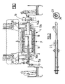
- la
figure 1 est une vue schématique d'un rouleau selon l'invention, en coupe longitudinale, implanté dans un four; - la
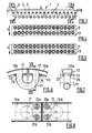
figure 2 est une vue schématique des tubes coaxiaux d'alimentation et d'évacuation du circuit de passage du fluide de refroidissement ; - la
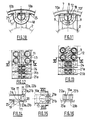
figure 3 est une vue schématique partielle en coupe longitudinale d'un rouleau selon l'invention ; - la
figure 4 est une vue schématique d'un plaque longitudinale d'assemblage des entrées et des sorties de fluide des anneaux aux pontages ; - la
figure 5 est une vue schématique d'une plaque longitudinale d'assemblage des extrémités des éléments sectoriels périphérique aux raccords internes ; - la
figure 6 est une vue en coupe transversale d'un raccord interne ; - la
figure 7 est une vue en coupe selon le plan VII-VII de lafigure 6 ; - la
figure 8 est une vue de dessus des extrémités jointives de deux éléments sectoriels périphériques ; - la
figure 9a est une vue en coupe selon le plan IX a-IX a de lafigure 3 ; - la
figure 9b est une vue en coupe selon le plan IX b-IX b de lafigure 3 ; - la
figure 10 est une vue en coupe selon le plan X-X de lafigure 12 , illustrant un raccord interne ; - la
figure 11 est une vue en coupe selon le plan XI-XI de lafigure 13 , illustrant un pontage ; - la
figure 12 est une vue de dessus d'une plaque longitudinale d'assemblage des extrémités des éléments sectoriels périphérique aux raccords internes ; - la
figure 13 est une vue de dessus d'une plaque longitudinale d'assemblage des entrées et des sorties de fluide des anneaux aux pontages ; - la
figure 14 est une vue schématique détaillée de la fixation des éléments sectoriels périphériques à une plaque longitudinale ; - la
figure 15 est une vue de dessus de l'extrémité d'un élément sectoriel périphérique ; - la
figure 16 est une vue en coupe selon le plan XVI-XVI de lafigure 15 ; et - la
figure 17 représente le dispositif de double étanchéité tournant pour l'alimentation et l'évacuation du fluide de refroidissement ; et - la
figure 18 est une vue partielle en couple longitudinale d'un rouleau selon l'invention.
- the
figure 1 is a schematic view of a roll according to the invention, in longitudinal section, implanted in an oven; - the
figure 2 is a schematic view of the coaxial feed tubes and evacuation of the cooling fluid passage circuit; - the
figure 3 is a partial schematic view in longitudinal section of a roller according to the invention; - the
figure 4 is a schematic view of a longitudinal assembly plate of the fluid inlets and outlets of the rings at the bypasses; - the
figure 5 is a schematic view of a longitudinal assembly plate of the ends of sectoral elements peripheral to the internal connections; - the
figure 6 is a cross-sectional view of an internal fitting; - the
figure 7 is a sectional view along plane VII-VII of thefigure 6 ; - the
figure 8 is a top view of the contiguous ends of two peripheral sectorial elements; - the
figure 9a is a sectional view along the plane IX a-IX a of thefigure 3 ; - the
figure 9b is a sectional view along the plane IX b-IX b of thefigure 3 ; - the
figure 10 is a sectional view along plane XX of thefigure 12 , illustrating an internal connection; - the
figure 11 is a sectional view according to plan XI-XI of thefigure 13 , illustrating a bypass; - the
figure 12 is a top view of a longitudinal assembly plate of the ends of sectoral elements peripheral to the internal connections; - the
figure 13 is a top view of a longitudinal assembly plate of the fluid inlets and outlets of the rings at the bypasses; - the
figure 14 is a detailed schematic view of the fixation of the elements sectoral peripheral to a longitudinal plate; - the
figure 15 is a top view of the end of a peripheral sectoral element; - the
figure 16 is a sectional view according to plan XVI-XVI of thefigure 15 ; and - the
figure 17 represents the rotating double seal device for the supply and discharge of the cooling fluid; and - the
figure 18 is a partial view in longitudinal torque of a roller according to the invention.
Le four d'incinération et/ou de combustion de déchets, illustré sur la
Un rouleau comprend une ossature creuse 2, métallique, formant une cage cylindrique et une surface de support 4 de combustible montée autour de ladite ossature 2.A roll comprises a
A chaque extrémité de l'ossature 2, un arbre 14a, 14b fait saillie vers l'extérieur de l'ossature 2 et est monté dans des paliers 15a, 15b disposés de part et d'autre du foyer du four. Un système d'entraînement 16 coopère avec un des arbres 2b afin d'entraîner le rouleau 1 en rotation. Afin d'assurer la rigidité du rouleau 1, l'ossature 2 est, en outre, pourvue d'une âme centrale 16 s'étendant longitudinalement entre les deux extrémités de ladite ossature 2. Ainsi, la flèche maximale de l'ossature 2 est faible. L'ossature 2 est creuse et permet le passage d'un gaz comburant au travers du rouleau 1.At each end of the
De manière avantageuse, l'ossature 2 pourra être équipée d'aubages fixes, non représentés, soudés sur l'âme centrale 16, permettant d'assurer une répartition homogène du gaz comburant au travers du rouleau 1 et l'attisage des déchets dans la zone de transit entre les rouleaux 1.Advantageously, the
La surface de support du combustible 4 comporte des moyens permettant le passage du gaz comburant au travers du rouleau. Ainsi, en fonctionnement, pour l'entretien de la combustion, un gaz comburant, tel que de l'air, est soufflé sensiblement verticalement au travers des rouleaux 1 (flèche y).The support surface of the fuel 4 comprises means allowing the passage of the oxidant gas through the roller. Thus, in operation, for the maintenance of the combustion, an oxidizing gas, such as air, is blown substantially vertically through the rollers 1 (arrow y).
Selon l'invention, la surface de support 4 est formée par un conduit 3 permettant le passage d'un fluide de refroidissement, de l'eau par exemple. Le conduit 3 comprend une pluralité d'anneaux 6 creux, coaxiaux à l'axe A, répartis sur la longueur dudit rouleau 1, comprenant chacun une entrée 7 et une sortie 8 de fluide, et des pontages 9, inter anneaux, raccordant de manière étanche la sortie de fluide 8 d'un anneau 6 à l'entrée 7 de fluide de l'anneau 6 suivant.According to the invention, the support surface 4 is formed by a
Les anneaux 6 sont écartés les uns des autres afin de former les orifices ou fentes 5 annulaires de passage du gaz comburant. La distance entre les anneaux 6 peut être constante ou variée sur la longueur du rouleau 1. La distance entre les anneaux 6 est choisie en fonction du type de déchets traités par l'installation et du débit de gaz comburant souhaité.The
Dans chacun des anneaux 6, le fluide de refroidissement circule dans le sens z, illustré sur les
En utilisation, on entraîne les rouleaux 1 en rotation dans un sens z contraire au sens de circulation w du fluide de refroidissement dans le circuit. Par conséquent, en cas de dégazage du liquide de refroidissement ou apparition d'une bulle, celle-ci se déplace d'anneau 6 en anneau 6 jusqu'au dernier, lors de la rotation du rouleau 1, et rejoint alors l'évacuation du fluide de refroidissement.In use, the
Dans le mode de réalisation représenté, détaillé sur les
L'ossature 2 porte au moins une plaque longitudinale 12 d'assemblage des entrées 7 et des sorties 8 de fluide des anneaux 6 aux pontages 9, représentée sur les
De même, l'ossature 2 porte cinq plaques longitudinales 13 d'assemblage des extrémités des éléments sectoriels périphérique 10a, 10b, 10c, 10d, 10e, 10f aux raccords internes 11, représentées sur les
Dans le mode de réalisation représenté, les plaques longitudinales 12 et 13 sont identiques et la fixation des éléments sectoriels à ces plaques 12, 13 est réalisée de manière identique. De même, les pontages 9 et les raccords internes 11 sont constitués d'éléments similaires. Toutefois, les raccords internes 11 s'étendent dans le plan de l'anneau alors que les pontages 9 sont inclinés par rapport à celui-ci afin de raccorder deux anneaux 6 successifs.In the embodiment shown, the
Les plaques longitudinales d'assemblage 12 et 13 sont fixées à l'âme centrale de l'ossature par l'intermédiaire de tiges radiales 18. En outre, les plaques longitudinales d'assemblage 12 et 13 comprennent des ouvertures circulaires 24 dans lesquelles les extrémités des pontages 9 ou des raccords internes 11 sont introduites. Les pontages 9 ou raccords internes 11 sont solidarisés aux plaques 12 et 13, par une soudure 19 par exemple.The
L'orifice 17, formé sur la face intérieure des éléments sectoriels10a, 10b, 10c, 10d, 10e, 10f, est bordé par une collerette 20. Comme représentée sur la
Les plaques longitudinales 12, 13 comprennent des moyens étanches de fixation des éléments sectoriels 10a, 10b, 10c, 10d, 10e, 10f. Dans l'exemple représenté, les plaques 12, 13 comportent deux orifices taraudés 23a, 23b, disposés de part et d'autre des ouvertures circulaires 24. Des vis 22a, 22b insérées dans des logements 21 a, 21 b des éléments sectoriels 10a, 10b, 10c, 10d, 10e, 10f sont destinées à être engagées dans les orifices taraudés 23a, 23b, afin de fixer les éléments sectoriels 10a, 10b, 10c, 10d, 10e, 10f à la plaque rigide 12, 13. Les logements 21 a, 21 b des vis 22a, 22b sont ménagés dans des extrémités pleines des éléments sectoriels 10a, 10b, 10c, 10d, 10e, 10f afin de ne pas mettre en contact direct les vis 22a, 22b avec le fluide de refroidissement, et limiter ainsi la corrosion. Les vis 22a, 22b utilisées pourront notamment être des vis à tête hexagonale.The
Lorsque l'on souhaite démonter une partie du circuit de passage du fluide de refroidissement, pour des besoins de maintenance notamment, on peut alors retirer les vis 22a, 22b afin de libérer un ou plusieurs éléments sectoriels amovibles 10a, 10b, 10c, 10d, 10e, 10f. Ainsi, une partie choisie du circuit peut être facilement démontée pour accéder à l'intérieur du rouleau ou remplacer les parties les plus usées.When it is desired to disassemble a portion of the cooling fluid passage circuit, especially for maintenance purposes, the
Afin de garantir l'étanchéité de la fixation, un joint 25 est logé dans une rainure formée dans la plaque 12, 13, venant en vis-à-vis de la collerette 20 de l'élément sectoriel 10a, 10b, 10c, 10d, 10e, 10f. Le joint 25 pourra notamment être réalisé en polytétrafluoroéthylène modifié.In order to guarantee the tightness of the fastening, a
Les deux extrémités des éléments sectoriels amovibles 10a, 10b, 10c, 10d, 10e, 10f sont séparées par un léger interstice autorisant une dilatation longitudinale desdits éléments sectoriels 10a, 10b, 10c, 10d, 10e, 10f.The two ends of the
Le fluide de refroidissement est introduit et évacué à l'intérieur de l'ossature 2 via un tube d'alimentation 26 et un tube d'évacuation 27, coaxiaux, d'axe A, représenté sur la
À l'extérieur du rouleau 1, les tubes d'alimentation 26 et d'évacuation 27 sont raccordés à un système de joint tournant 30, illustré sur la
L'invention est décrite dans ce qui précède à titre d'exemple. Il est entendu que l'homme du métier est à même de réaliser différentes variantes de réalisation de l'invention sans pour autant sortir du cadre de l'invention.The invention is described in the foregoing by way of example. It is understood that the skilled person is able to achieve different embodiments of the invention without departing from the scope of the invention.
Claims (13)
Priority Applications (1)
| Application Number | Priority Date | Filing Date | Title |
|---|---|---|---|
| PL09290304T PL2113718T3 (en) | 2008-04-28 | 2009-04-24 | Cylindrical combustion grate for a furnace with a cooling system |
Applications Claiming Priority (1)
| Application Number | Priority Date | Filing Date | Title |
|---|---|---|---|
| FR0852838A FR2930627B1 (en) | 2008-04-28 | 2008-04-28 | ROLL FOR OVEN GRILL EQUIPPED WITH COOLING CIRCUIT |
Publications (3)
| Publication Number | Publication Date |
|---|---|
| EP2113718A2 true EP2113718A2 (en) | 2009-11-04 |
| EP2113718A3 EP2113718A3 (en) | 2014-08-20 |
| EP2113718B1 EP2113718B1 (en) | 2018-07-25 |
Family
ID=39885060
Family Applications (1)
| Application Number | Title | Priority Date | Filing Date |
|---|---|---|---|
| EP09290304.6A Active EP2113718B1 (en) | 2008-04-28 | 2009-04-24 | Cylindrical combustion grate for a furnace with a cooling system |
Country Status (4)
| Country | Link |
|---|---|
| EP (1) | EP2113718B1 (en) |
| ES (1) | ES2684436T3 (en) |
| FR (1) | FR2930627B1 (en) |
| PL (1) | PL2113718T3 (en) |
Citations (4)
| Publication number | Priority date | Publication date | Assignee | Title |
|---|---|---|---|---|
| GB251849A (en) | 1925-10-01 | 1926-05-13 | Tikhon Makariew | Mechanical grate |
| EP0124826A2 (en) | 1983-05-05 | 1984-11-14 | Deutsche Babcock Anlagen Aktiengesellschaft | Cylindrical grate for incinerators |
| US5042401A (en) | 1990-06-04 | 1991-08-27 | Westinghouse Electric Corp. | Water cooled rolling grate incinerator |
| FR2908180A1 (en) | 2006-11-02 | 2008-05-09 | Vinci Environnement Soc Par Ac | Roller for oven grid, has fuel support surface formed by duct permitting passage of cooling fluid and forming helical winding around axis, where surface has fuel passage unit for passage of fuel through roller |
-
2008
- 2008-04-28 FR FR0852838A patent/FR2930627B1/en active Active
-
2009
- 2009-04-24 ES ES09290304.6T patent/ES2684436T3/en active Active
- 2009-04-24 PL PL09290304T patent/PL2113718T3/en unknown
- 2009-04-24 EP EP09290304.6A patent/EP2113718B1/en active Active
Patent Citations (4)
| Publication number | Priority date | Publication date | Assignee | Title |
|---|---|---|---|---|
| GB251849A (en) | 1925-10-01 | 1926-05-13 | Tikhon Makariew | Mechanical grate |
| EP0124826A2 (en) | 1983-05-05 | 1984-11-14 | Deutsche Babcock Anlagen Aktiengesellschaft | Cylindrical grate for incinerators |
| US5042401A (en) | 1990-06-04 | 1991-08-27 | Westinghouse Electric Corp. | Water cooled rolling grate incinerator |
| FR2908180A1 (en) | 2006-11-02 | 2008-05-09 | Vinci Environnement Soc Par Ac | Roller for oven grid, has fuel support surface formed by duct permitting passage of cooling fluid and forming helical winding around axis, where surface has fuel passage unit for passage of fuel through roller |
Also Published As
| Publication number | Publication date |
|---|---|
| EP2113718B1 (en) | 2018-07-25 |
| FR2930627A1 (en) | 2009-10-30 |
| PL2113718T3 (en) | 2018-11-30 |
| FR2930627B1 (en) | 2010-06-04 |
| EP2113718A3 (en) | 2014-08-20 |
| ES2684436T3 (en) | 2018-10-02 |
Similar Documents
| Publication | Publication Date | Title |
|---|---|---|
| EP1561075B1 (en) | Condensation heat exchanger with plastic casing | |
| CA2475081C (en) | Device to control the play in a gas turbine | |
| EP0182716B1 (en) | Tip-sealing shroud for a gas turbine | |
| EP2531779B1 (en) | Condensing heat exchanger for multiple fluids and device for the production of hot fluids comprising such a heat exchanger | |
| EP3405723B1 (en) | Condensation heat exchanger provided with a heat exchange device | |
| FR2662746A1 (en) | GAS TURBINE ENGINE ENVELOPE SEGMENT AND GAME ENCLOSURE CONTROL ASSEMBLY. | |
| EP1526253B1 (en) | Labyrinth seal for a turbo machine | |
| FR2698914A1 (en) | Rocket motor with liquid propellants with derivative flow and integrated gas generator. | |
| EP0515669B1 (en) | Plate heat exchanger | |
| EP2113718B1 (en) | Cylindrical combustion grate for a furnace with a cooling system | |
| EP1399597A1 (en) | Device for loading a shaft furnace | |
| FR2516597A1 (en) | ANNULAR AIR-COOLED WEAR AND SEAL DEVICE FOR GAS TURBINE WHEEL WELDING OR COMPRESSOR | |
| EP0133604B1 (en) | Boiler with a helical heat exchanger | |
| EP3797248A1 (en) | Turbine engine combustion chamber bottom | |
| FR2972789A1 (en) | CONDENSING GAS HEATING APPARATUS | |
| EP1921379B1 (en) | Kiln cylinder provided with cooling fluid conduit | |
| FR2959000A1 (en) | CONDUIT FOR AN EVAPORATION CIRCUIT FOR COMBUSTION PRODUCTS AND COMBUSTION AIR SUPPLIES IN A FUMING FACILITY | |
| EP0277070B1 (en) | Thermal generator tubular exchanger plate | |
| FR2727744A1 (en) | Solid fuel burner and installation | |
| FR2555794A1 (en) | Fast-neutron nuclear reactor fitted with emergency cooling means | |
| FR2582786A1 (en) | INDUSTRIAL GAS HOT WATER HEATER | |
| FR2547900A1 (en) | GAS BURNER | |
| FR2559834A1 (en) | Turbine ring | |
| BE1009083A4 (en) | Expansion joint for the combined cycle power plants. | |
| EP3853445A1 (en) | Turbine seal |
Legal Events
| Date | Code | Title | Description |
|---|---|---|---|
| PUAI | Public reference made under article 153(3) epc to a published international application that has entered the european phase |
Free format text: ORIGINAL CODE: 0009012 |
|
| AK | Designated contracting states |
Kind code of ref document: A2 Designated state(s): AT BE BG CH CY CZ DE DK EE ES FI FR GB GR HR HU IE IS IT LI LT LU LV MC MK MT NL NO PL PT RO SE SI SK TR |
|
| PUAL | Search report despatched |
Free format text: ORIGINAL CODE: 0009013 |
|
| AK | Designated contracting states |
Kind code of ref document: A3 Designated state(s): AT BE BG CH CY CZ DE DK EE ES FI FR GB GR HR HU IE IS IT LI LT LU LV MC MK MT NL NO PL PT RO SE SI SK TR |
|
| AX | Request for extension of the european patent |
Extension state: AL BA RS |
|
| RIC1 | Information provided on ipc code assigned before grant |
Ipc: F23G 5/00 20060101AFI20140714BHEP Ipc: F23H 9/02 20060101ALI20140714BHEP |
|
| 17P | Request for examination filed |
Effective date: 20150220 |
|
| STAA | Information on the status of an ep patent application or granted ep patent |
Free format text: STATUS: EXAMINATION IS IN PROGRESS |
|
| 17Q | First examination report despatched |
Effective date: 20170308 |
|
| GRAP | Despatch of communication of intention to grant a patent |
Free format text: ORIGINAL CODE: EPIDOSNIGR1 |
|
| STAA | Information on the status of an ep patent application or granted ep patent |
Free format text: STATUS: GRANT OF PATENT IS INTENDED |
|
| INTG | Intention to grant announced |
Effective date: 20180227 |
|
| GRAS | Grant fee paid |
Free format text: ORIGINAL CODE: EPIDOSNIGR3 |
|
| GRAA | (expected) grant |
Free format text: ORIGINAL CODE: 0009210 |
|
| STAA | Information on the status of an ep patent application or granted ep patent |
Free format text: STATUS: THE PATENT HAS BEEN GRANTED |
|
| AK | Designated contracting states |
Kind code of ref document: B1 Designated state(s): AT BE BG CH CY CZ DE DK EE ES FI FR GB GR HR HU IE IS IT LI LT LU LV MC MK MT NL NO PL PT RO SE SI SK TR |
|
| REG | Reference to a national code |
Ref country code: GB Ref legal event code: FG4D Free format text: NOT ENGLISH |
|
| REG | Reference to a national code |
Ref country code: CH Ref legal event code: EP |
|
| REG | Reference to a national code |
Ref country code: CH Ref legal event code: NV Representative=s name: NOVAGRAAF INTERNATIONAL SA, CH Ref country code: AT Ref legal event code: REF Ref document number: 1022177 Country of ref document: AT Kind code of ref document: T Effective date: 20180815 |
|
| REG | Reference to a national code |
Ref country code: DE Ref legal event code: R096 Ref document number: 602009053425 Country of ref document: DE |
|
| REG | Reference to a national code |
Ref country code: IE Ref legal event code: FG4D Free format text: LANGUAGE OF EP DOCUMENT: FRENCH |
|
| REG | Reference to a national code |
Ref country code: ES Ref legal event code: FG2A Ref document number: 2684436 Country of ref document: ES Kind code of ref document: T3 Effective date: 20181002 |
|
| REG | Reference to a national code |
Ref country code: NL Ref legal event code: MP Effective date: 20180725 |
|
| REG | Reference to a national code |
Ref country code: LT Ref legal event code: MG4D |
|
| PG25 | Lapsed in a contracting state [announced via postgrant information from national office to epo] |
Ref country code: NL Free format text: LAPSE BECAUSE OF FAILURE TO SUBMIT A TRANSLATION OF THE DESCRIPTION OR TO PAY THE FEE WITHIN THE PRESCRIBED TIME-LIMIT Effective date: 20180725 |
|
| REG | Reference to a national code |
Ref country code: AT Ref legal event code: MK05 Ref document number: 1022177 Country of ref document: AT Kind code of ref document: T Effective date: 20180725 |
|
| PG25 | Lapsed in a contracting state [announced via postgrant information from national office to epo] |
Ref country code: NO Free format text: LAPSE BECAUSE OF FAILURE TO SUBMIT A TRANSLATION OF THE DESCRIPTION OR TO PAY THE FEE WITHIN THE PRESCRIBED TIME-LIMIT Effective date: 20181025 Ref country code: SE Free format text: LAPSE BECAUSE OF FAILURE TO SUBMIT A TRANSLATION OF THE DESCRIPTION OR TO PAY THE FEE WITHIN THE PRESCRIBED TIME-LIMIT Effective date: 20180725 Ref country code: AT Free format text: LAPSE BECAUSE OF FAILURE TO SUBMIT A TRANSLATION OF THE DESCRIPTION OR TO PAY THE FEE WITHIN THE PRESCRIBED TIME-LIMIT Effective date: 20180725 Ref country code: IS Free format text: LAPSE BECAUSE OF FAILURE TO SUBMIT A TRANSLATION OF THE DESCRIPTION OR TO PAY THE FEE WITHIN THE PRESCRIBED TIME-LIMIT Effective date: 20181125 Ref country code: GR Free format text: LAPSE BECAUSE OF FAILURE TO SUBMIT A TRANSLATION OF THE DESCRIPTION OR TO PAY THE FEE WITHIN THE PRESCRIBED TIME-LIMIT Effective date: 20181026 Ref country code: FI Free format text: LAPSE BECAUSE OF FAILURE TO SUBMIT A TRANSLATION OF THE DESCRIPTION OR TO PAY THE FEE WITHIN THE PRESCRIBED TIME-LIMIT Effective date: 20180725 Ref country code: BG Free format text: LAPSE BECAUSE OF FAILURE TO SUBMIT A TRANSLATION OF THE DESCRIPTION OR TO PAY THE FEE WITHIN THE PRESCRIBED TIME-LIMIT Effective date: 20181025 Ref country code: LT Free format text: LAPSE BECAUSE OF FAILURE TO SUBMIT A TRANSLATION OF THE DESCRIPTION OR TO PAY THE FEE WITHIN THE PRESCRIBED TIME-LIMIT Effective date: 20180725 |
|
| PG25 | Lapsed in a contracting state [announced via postgrant information from national office to epo] |
Ref country code: HR Free format text: LAPSE BECAUSE OF FAILURE TO SUBMIT A TRANSLATION OF THE DESCRIPTION OR TO PAY THE FEE WITHIN THE PRESCRIBED TIME-LIMIT Effective date: 20180725 Ref country code: LV Free format text: LAPSE BECAUSE OF FAILURE TO SUBMIT A TRANSLATION OF THE DESCRIPTION OR TO PAY THE FEE WITHIN THE PRESCRIBED TIME-LIMIT Effective date: 20180725 |
|
| REG | Reference to a national code |
Ref country code: DE Ref legal event code: R097 Ref document number: 602009053425 Country of ref document: DE |
|
| PG25 | Lapsed in a contracting state [announced via postgrant information from national office to epo] |
Ref country code: EE Free format text: LAPSE BECAUSE OF FAILURE TO SUBMIT A TRANSLATION OF THE DESCRIPTION OR TO PAY THE FEE WITHIN THE PRESCRIBED TIME-LIMIT Effective date: 20180725 Ref country code: RO Free format text: LAPSE BECAUSE OF FAILURE TO SUBMIT A TRANSLATION OF THE DESCRIPTION OR TO PAY THE FEE WITHIN THE PRESCRIBED TIME-LIMIT Effective date: 20180725 Ref country code: CZ Free format text: LAPSE BECAUSE OF FAILURE TO SUBMIT A TRANSLATION OF THE DESCRIPTION OR TO PAY THE FEE WITHIN THE PRESCRIBED TIME-LIMIT Effective date: 20180725 Ref country code: IT Free format text: LAPSE BECAUSE OF FAILURE TO SUBMIT A TRANSLATION OF THE DESCRIPTION OR TO PAY THE FEE WITHIN THE PRESCRIBED TIME-LIMIT Effective date: 20180725 |
|
| PG25 | Lapsed in a contracting state [announced via postgrant information from national office to epo] |
Ref country code: SK Free format text: LAPSE BECAUSE OF FAILURE TO SUBMIT A TRANSLATION OF THE DESCRIPTION OR TO PAY THE FEE WITHIN THE PRESCRIBED TIME-LIMIT Effective date: 20180725 Ref country code: DK Free format text: LAPSE BECAUSE OF FAILURE TO SUBMIT A TRANSLATION OF THE DESCRIPTION OR TO PAY THE FEE WITHIN THE PRESCRIBED TIME-LIMIT Effective date: 20180725 |
|
| PLBE | No opposition filed within time limit |
Free format text: ORIGINAL CODE: 0009261 |
|
| STAA | Information on the status of an ep patent application or granted ep patent |
Free format text: STATUS: NO OPPOSITION FILED WITHIN TIME LIMIT |
|
| 26N | No opposition filed |
Effective date: 20190426 |
|
| REG | Reference to a national code |
Ref country code: DE Ref legal event code: R082 Ref document number: 602009053425 Country of ref document: DE |
|
| PG25 | Lapsed in a contracting state [announced via postgrant information from national office to epo] |
Ref country code: SI Free format text: LAPSE BECAUSE OF FAILURE TO SUBMIT A TRANSLATION OF THE DESCRIPTION OR TO PAY THE FEE WITHIN THE PRESCRIBED TIME-LIMIT Effective date: 20180725 |
|
| PG25 | Lapsed in a contracting state [announced via postgrant information from national office to epo] |
Ref country code: MC Free format text: LAPSE BECAUSE OF FAILURE TO SUBMIT A TRANSLATION OF THE DESCRIPTION OR TO PAY THE FEE WITHIN THE PRESCRIBED TIME-LIMIT Effective date: 20180725 Ref country code: LU Free format text: LAPSE BECAUSE OF NON-PAYMENT OF DUE FEES Effective date: 20190424 |
|
| PG25 | Lapsed in a contracting state [announced via postgrant information from national office to epo] |
Ref country code: TR Free format text: LAPSE BECAUSE OF FAILURE TO SUBMIT A TRANSLATION OF THE DESCRIPTION OR TO PAY THE FEE WITHIN THE PRESCRIBED TIME-LIMIT Effective date: 20180725 |
|
| PG25 | Lapsed in a contracting state [announced via postgrant information from national office to epo] |
Ref country code: PT Free format text: LAPSE BECAUSE OF FAILURE TO SUBMIT A TRANSLATION OF THE DESCRIPTION OR TO PAY THE FEE WITHIN THE PRESCRIBED TIME-LIMIT Effective date: 20181125 |
|
| PG25 | Lapsed in a contracting state [announced via postgrant information from national office to epo] |
Ref country code: CY Free format text: LAPSE BECAUSE OF FAILURE TO SUBMIT A TRANSLATION OF THE DESCRIPTION OR TO PAY THE FEE WITHIN THE PRESCRIBED TIME-LIMIT Effective date: 20180725 |
|
| PG25 | Lapsed in a contracting state [announced via postgrant information from national office to epo] |
Ref country code: MT Free format text: LAPSE BECAUSE OF FAILURE TO SUBMIT A TRANSLATION OF THE DESCRIPTION OR TO PAY THE FEE WITHIN THE PRESCRIBED TIME-LIMIT Effective date: 20180725 Ref country code: HU Free format text: LAPSE BECAUSE OF FAILURE TO SUBMIT A TRANSLATION OF THE DESCRIPTION OR TO PAY THE FEE WITHIN THE PRESCRIBED TIME-LIMIT; INVALID AB INITIO Effective date: 20090424 |
|
| PG25 | Lapsed in a contracting state [announced via postgrant information from national office to epo] |
Ref country code: MK Free format text: LAPSE BECAUSE OF FAILURE TO SUBMIT A TRANSLATION OF THE DESCRIPTION OR TO PAY THE FEE WITHIN THE PRESCRIBED TIME-LIMIT Effective date: 20180725 |
|
| PGFP | Annual fee paid to national office [announced via postgrant information from national office to epo] |
Ref country code: IE Payment date: 20230321 Year of fee payment: 15 Ref country code: FR Payment date: 20230313 Year of fee payment: 15 |
|
| PGFP | Annual fee paid to national office [announced via postgrant information from national office to epo] |
Ref country code: PL Payment date: 20230320 Year of fee payment: 15 |
|
| PGFP | Annual fee paid to national office [announced via postgrant information from national office to epo] |
Ref country code: ES Payment date: 20230504 Year of fee payment: 15 Ref country code: DE Payment date: 20230412 Year of fee payment: 15 Ref country code: CH Payment date: 20230502 Year of fee payment: 15 |
|
| PGFP | Annual fee paid to national office [announced via postgrant information from national office to epo] |
Ref country code: BE Payment date: 20230424 Year of fee payment: 15 |
|
| PGFP | Annual fee paid to national office [announced via postgrant information from national office to epo] |
Ref country code: GB Payment date: 20230424 Year of fee payment: 15 |
|
| REG | Reference to a national code |
Ref country code: CH Ref legal event code: PK Free format text: RECTIFICATIONS |
|
| REG | Reference to a national code |
Ref country code: GB Ref legal event code: 732E Free format text: REGISTERED BETWEEN 20231012 AND 20231018 |
|
| REG | Reference to a national code |
Ref country code: DE Ref legal event code: R081 Ref document number: 602009053425 Country of ref document: DE Owner name: VINCI CONSTRUCTION GRANDS PROJETS, FR Free format text: FORMER OWNER: VINCI ENVIRONNEMENT, RUEIL MALMAISON, FR |
|
| REG | Reference to a national code |
Ref country code: BE Ref legal event code: PD Owner name: VINCI CONSTRUCTION GRANDS PROJETS; FR Free format text: DETAILS ASSIGNMENT: CHANGE OF OWNER(S), MERGE; FORMER OWNER NAME: VINCI ENVIRONNEMENT Effective date: 20231026 |