EP2113718A2 - Zylinderischer Verbrennungsrost für einen Ofen mit einem Kühlkreislauf - Google Patents
Zylinderischer Verbrennungsrost für einen Ofen mit einem Kühlkreislauf Download PDFInfo
- Publication number
- EP2113718A2 EP2113718A2 EP09290304A EP09290304A EP2113718A2 EP 2113718 A2 EP2113718 A2 EP 2113718A2 EP 09290304 A EP09290304 A EP 09290304A EP 09290304 A EP09290304 A EP 09290304A EP 2113718 A2 EP2113718 A2 EP 2113718A2
- Authority
- EP
- European Patent Office
- Prior art keywords
- roller
- rings
- frame
- oven rack
- rack according
- Prior art date
- Legal status (The legal status is an assumption and is not a legal conclusion. Google has not performed a legal analysis and makes no representation as to the accuracy of the status listed.)
- Granted
Links
Images


Classifications
-
- F—MECHANICAL ENGINEERING; LIGHTING; HEATING; WEAPONS; BLASTING
- F23—COMBUSTION APPARATUS; COMBUSTION PROCESSES
- F23G—CREMATION FURNACES; CONSUMING WASTE PRODUCTS BY COMBUSTION
- F23G5/00—Incineration of waste; Incinerator constructions; Details, accessories or control therefor
-
- F—MECHANICAL ENGINEERING; LIGHTING; HEATING; WEAPONS; BLASTING
- F23—COMBUSTION APPARATUS; COMBUSTION PROCESSES
- F23H—GRATES; CLEANING OR RAKING GRATES
- F23H9/00—Revolving-grates; Rocking or shaking grates
- F23H9/02—Revolving cylindrical grates
-
- F—MECHANICAL ENGINEERING; LIGHTING; HEATING; WEAPONS; BLASTING
- F23—COMBUSTION APPARATUS; COMBUSTION PROCESSES
- F23H—GRATES; CLEANING OR RAKING GRATES
- F23H2700/00—Grates characterised by special features or applications
- F23H2700/004—Rotary grates with horizontal axis
-
- F—MECHANICAL ENGINEERING; LIGHTING; HEATING; WEAPONS; BLASTING
- F23—COMBUSTION APPARATUS; COMBUSTION PROCESSES
- F23H—GRATES; CLEANING OR RAKING GRATES
- F23H2900/00—Special features of combustion grates
- F23H2900/03021—Liquid cooled grates
Definitions
- the invention relates to a roll for a grate of combustion and / or incineration furnace, and in particular for the incineration of waste.
- the invention also relates to an incineration furnace and the use of such an oven.
- rollers for combustion and / or incineration furnaces are well known in the prior art.
- the rolls are composed of a cylindrical metal frame on which bars are arranged to form a waste support surface. Annular slots are formed to allow combustion air to pass through the roll. Rollers of this type are described in particular in the document EP 0 124 826 .
- the bars on which the waste is placed are subjected to very severe thermal stresses because of the high temperature levels prevailing in the combustion zone and the large temperature differences between the heatings due to the radiation and the contact of the materials in combustion and cooling from the blowing of combustion air.
- These large thermal stresses cause expansions and contractions of the constituent material of the bars causing dimensional variations and offsets between the bars and thus making possible the passage of clinker or metal casting between the bars.
- the air passing through the rollers is no longer distributed properly.
- the grids equipped with such rollers can only partially exploit the calorific value of the waste. Indeed, in order to limit the thermal stresses exerted on the bars, the temperature in the furnace hearth is limited so that the combustion of some waste remains incomplete.
- rollers with a cooling device for maintaining the bars at a restricted temperature.
- the document US 5,042,401 describes a roller having hollow longitudinal bars forming the outer surface of the waste support and allowing the passage of a cooling fluid.
- the bars are fed in parallel by means of a flow distribution device disposed at one end of said roll.
- the bars undergo significant deformations related to an "all or nothing" exposure in the furnace of the incineration furnace.
- the risk of blockage of the rollers by the transit areas between two adjacent rollers and / or slag falls in these transit areas are important.
- the document GB 251 849 describes a roller composed of a cylindrical central tube inside which circulates a cooling fluid and around which are arranged curved bars forming rings around said central tube.
- the cooling circuit only allows a poor cooling of the surface of the bars actually in contact with the products to be incinerated and the thermal stresses applied on the bars are only slightly decreased.
- rollers comprising a framework, a support surface mounted around the framework and formed by a conduit for passage of a cooling fluid forming a helical winding around the longitudinal axis of the roller.
- a cooling fluid forming a helical winding around the longitudinal axis of the roller.
- the particular shape of the passage of the cooling fluid ensures uniform cooling of the support surface.
- the shape of the winding serves to purge the air present in the duct during the rotation of the roller.
- the invention aims to remedy these problems by proposing a roll for an oven rack resistant to the temperature conditions prevailing in the oven, in order to limit the maintenance operations and to allow the incineration of the waste at high temperatures so as to obtain a complete combustion of waste, and whose manufacture, maintenance and assembly are simple.
- the manufacture and assembly of the rollers according to the invention are relatively easy because the conduit for the passage of cooling is composed of rings simpler to make and assemble than turns.
- the particular shape of the coolant passage conduit also ensures uniform cooling of the support surface of the fuel.
- the annular orientation of the conduit limits dilations and contractions. Consequently, the support surface of the fuel is subjected only to slight expansions and / or contractions during the rotation of the roller and its successive exposures to the combustion chamber and, to the blowing zone of the combustion air. Thus, the dimensional variations of the passage means of the oxidizing gas are limited.
- inter-ring bypasses are fixed to the framework.
- the frame carries at least one longitudinal assembly plate of the fluid inlets and outlets of the rings to the bridges.
- the bridges are U-shaped tubes.
- the cooling fluid inlets and outlets of the rings are arranged in such a way that the cooling fluid circulates in the same direction in each of the rings.
- the bridges extend in a plane inclined at an angle of between 0 and 90 ° relative to the plane of the rings.
- the rings comprise a plurality of peripheral sectorial elements communicating via internal connections. Therefore, the mounting of the rings, as well as access to the interior of the roll for maintenance operations and change of elements are simple operations.
- connections are fixed to the frame.
- the frame carries longitudinal plates for assembling the ends of the peripheral sectoral elements to the internal connections.
- connections are U-shaped tubes.
- the rings consist of six sectoral elements.
- the invention relates to a combustion and / or incineration furnace comprising a plurality of rollers according to the first aspect of the invention.
- the invention relates to the use of a combustion furnace according to the second aspect of the invention, in which at least one roller is rotated about its longitudinal axis A in a direction z and the cooling fluid passage is fed so that the cooling fluid moves in a direction w around the framework, inverted with respect to z.
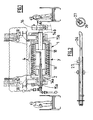
- the incineration and / or waste combustion furnace illustrated on the figure 1 , is equipped with several rollers 1 according to the invention.
- the rollers 1 are cascaded and driven in rotation at relatively low speeds, from 0.5 to 3 revolutions / hour approximately, around parallel horizontal axes A in order to allow the waste to advance into the furnace.
- the grids comprise about 6 rolls of about 1 meter 50 in diameter.
- the rollers follow one another in the direction of displacement of the fuel, according to a downward slope ⁇ of about 15 °.
- a roll comprises a hollow metal frame 2 forming a cylindrical cage and a fuel support surface 4 mounted around said framework 2.
- a shaft 14a, 14b protrudes outwardly of the frame 2 and is mounted in bearings 15a, 15b disposed on either side of the furnace hearth.
- a drive system 16 cooperates with one of the shafts 2b to drive the roller 1 in rotation.
- the frame 2 is furthermore provided with a central core 16 extending longitudinally between the two ends of said frame 2. Thus, the maximum deflection of the frame 2 is low.
- the frame 2 is hollow and allows the passage of an oxidizing gas through the roller 1.
- the frame 2 may be equipped with fixed vanes, not shown, welded on the central core 16, to ensure a homogeneous distribution of the oxidant gas through the roller 1 and the attraction of waste in the transit area between the rollers 1.
- the support surface of the fuel 4 comprises means allowing the passage of the oxidant gas through the roller.
- an oxidizing gas such as air, is blown substantially vertically through the rollers 1 (arrow y).
- the support surface 4 is formed by a conduit 3 allowing the passage of a cooling fluid, water for example.
- the duct 3 comprises a plurality of hollow rings 6, coaxial with the axis A, distributed along the length of said roll 1, each comprising an inlet 7 and an outlet 8 of fluid, and inter-rings 9, connecting in a manner sealing the fluid outlet 8 of a ring 6 at the fluid inlet 7 of the next ring 6.
- the rings 6 are spaced from each other to form the orifices or annular slots for the passage of the oxidizing gas.
- the distance between the rings 6 can be constant or varied over the length of the roller 1.
- the distance between the rings 6 is chosen according to the type of waste treated by the installation and the desired oxidant gas flow rate.
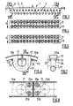
- the cooling fluid flows in the z direction, illustrated on the Figures 9a and 9b .
- the bridges extend in a plane inclined at an angle between 0 and 90 ° relative to the plane of the rings.
- the cooling fluid passage circuit is wound around the frame 2.
- the rollers 1 are rotated in a direction opposite to the direction of circulation w of the cooling fluid in the circuit. Therefore, in case of coolant degassing or appearance of a bubble, it moves from ring 6 to ring 6 to the last, during the rotation of the roll 1, and then joins the evacuation of the cooling fluid.
- the rings are composed of six peripheral sectoral elements 10a, 10b, 10c, 10d, 10e, 10f removable communicating, in a sealed manner, via internal connections 11, or inter-element bridges, fixed to the frame 2.
- the sectoral elements 10a , 10b, 10c, 10d, 10e, 10f are hollow bars, made of cast iron, and bent longitudinally at an angle of about 60 °.
- the elements 10a, 10b, 10c, 10d, 10e, 10f have at each end of their inner face a passage 17 for the passage of the cooling fluid.
- the internal connections 11 are here formed of U-shaped tubing.
- the frame 2 carries at least one longitudinal plate 12 for assembling the inlets 7 and the fluid outlets 8 of the rings 6 to the bridges 9, shown in FIGS. figures 4 , 11 and 13 .
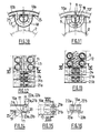
- the longitudinal plate 12 extends over the entire length of the roll 1 and supports all the bridges 13 of the roll.
- the longitudinal plate 12 furthermore makes it possible to support the ends of the rings 6 comprising the fluid inlets and outlets and to fix them in a sealed manner by the fastening means detailed thereafter.
- the frame 2 carries five longitudinal plates 13 for joining the ends of the peripheral sectoral elements 10a, 10b, 10c, 10d, 10e, 10f to the internal connections 11, shown in FIGS. figures 5 , 10 and 12 .
- These plates 13 extend, in the embodiment shown, over the entire length of the rollers 1 and support the internal connections 11.
- the plates also allow to receive and fix the ends of the sectoral elements 10a, 10b, 10c, 10d , 10e, 10f to the frame 2.
- the longitudinal plates 12 and 13 are identical and the attachment of the sectorial elements to these plates 12, 13 is performed identically.
- the bridging 9 and the internal connections 11 consist of similar elements.
- the internal connections 11 extend in the plane of the ring while the bridges 9 are inclined relative thereto in order to connect two successive rings 6.
- the longitudinal assembly plates 12 and 13 are fixed to the central core of the framework by means of radial rods 18.
- the longitudinal assembly plates 12 and 13 comprise circular openings 24 in which the ends bridging 9 or internal connections 11 are introduced.
- the bridging 9 or internal connectors 11 are secured to the plates 12 and 13, by a weld 19 for example.
- the orifice 17, formed on the inner face of the sectorial elements 10a, 10b, 10c, 10d, 10e, 10f, is bordered by a collar 20.
- the underside of the sectoral elements 10a, 10b, 10c, 10d, 10e, 10f is positioned against the rigid plate 12, 13 and the end of the internal connectors 11 (or bridges 9) is inserted inside said flange 20 to ensure the connection between the inner connector 11 and the sectoral element 10a.
- the longitudinal plates 12, 13 comprise sealed means for fastening sector elements 10a, 10b, 10c, 10d, 10e, 10f.
- the plates 12, 13 comprise two threaded orifices 23a, 23b, arranged on either side of the circular openings 24.
- Screws 22a, 22b inserted in housings 21a, 21b sectoral elements 10a, 10b, 10c, 10d, 10e, 10f are intended to be engaged in the threaded orifices 23a, 23b, in order to fix the sectoral elements 10a, 10b, 10c, 10d, 10e, 10f to the rigid plate 12, 13.
- the housings 21 a, 21 b screws 22a, 22b are formed in the solid ends of sector elements 10a, 10b, 10c, 10d, 10e, 10f so as not to put the screws 22a, 22b into direct contact with the cooling fluid, and to limit thus corrosion.
- the screws 22a, 22b used may in particular be hexagonal screw.
- the screws 22a, 22b can then be removed in order to release one or more removable sectoral elements 10a, 10b, 10c, 10d, 10th, 10f.
- a selected portion of the circuit can be easily disassembled to access the interior of the roll or replace the most worn parts.
- a seal 25 is housed in a groove formed in the plate 12, 13, coming opposite the flange 20 of the sectoral element 10a, 10b, 10c, 10d, 10th, 10f.
- the seal 25 may in particular be made of modified polytetrafluoroethylene.
- the two ends of the removable sector elements 10a, 10b, 10c, 10d, 10e, 10f are separated by a small gap allowing longitudinal expansion of said sectoral elements 10a, 10b, 10c, 10d, 10e, 10f.
- the cooling fluid is introduced and evacuated inside the framework 2 via a coaxial feed tube 26 and a discharge tube 27, of axis A, represented on the figure 2 .
- the supply and discharge tubes 26 are introduced into the framework by the end of the roll 1, opposite to the drive system 16.
- the fluid inlet 7 of the first ring 6 is connected to the supply tube 26 in fluid via a connection tube 28.
- the fluid outlet of the last ring 6 is connected to the discharge tube 27 of the fluid via a connecting tube 29.
- the feed and discharge tubes 27 are connected to a rotating joint system 30, shown in FIG. figure 14 by means of a flange / flange assembly provided with an O-ring.
- the rotary joint is connected, on the one hand, to a fluid supply network 35 via a conduit 36 provided with a valve 37 and, on the other hand, with an evacuation network 32 via a conduit 33 provided with a valve 34.
Landscapes
- Engineering & Computer Science (AREA)
- Mechanical Engineering (AREA)
- General Engineering & Computer Science (AREA)
- Chemical & Material Sciences (AREA)
- Combustion & Propulsion (AREA)
- Rollers For Roller Conveyors For Transfer (AREA)
Priority Applications (1)
| Application Number | Priority Date | Filing Date | Title |
|---|---|---|---|
| PL09290304T PL2113718T3 (pl) | 2008-04-28 | 2009-04-24 | Walec dla rusztu pieca do spalania, wyposażony w przewód płynu chłodzącego |
Applications Claiming Priority (1)
| Application Number | Priority Date | Filing Date | Title |
|---|---|---|---|
| FR0852838A FR2930627B1 (fr) | 2008-04-28 | 2008-04-28 | Rouleau pour grille de four equipe d'un circuit de refroidissement |
Publications (3)
| Publication Number | Publication Date |
|---|---|
| EP2113718A2 true EP2113718A2 (de) | 2009-11-04 |
| EP2113718A3 EP2113718A3 (de) | 2014-08-20 |
| EP2113718B1 EP2113718B1 (de) | 2018-07-25 |
Family
ID=39885060
Family Applications (1)
| Application Number | Title | Priority Date | Filing Date |
|---|---|---|---|
| EP09290304.6A Active EP2113718B1 (de) | 2008-04-28 | 2009-04-24 | Zylindrischer Verbrennungsrost für einen Ofen mit einem Kühlkreislauf |
Country Status (4)
| Country | Link |
|---|---|
| EP (1) | EP2113718B1 (de) |
| ES (1) | ES2684436T3 (de) |
| FR (1) | FR2930627B1 (de) |
| PL (1) | PL2113718T3 (de) |
Citations (4)
| Publication number | Priority date | Publication date | Assignee | Title |
|---|---|---|---|---|
| GB251849A (en) | 1925-10-01 | 1926-05-13 | Tikhon Makariew | Mechanical grate |
| EP0124826A2 (de) | 1983-05-05 | 1984-11-14 | Deutsche Babcock Anlagen Aktiengesellschaft | Walzenrost für Müllverbrennungsanlagen |
| US5042401A (en) | 1990-06-04 | 1991-08-27 | Westinghouse Electric Corp. | Water cooled rolling grate incinerator |
| FR2908180A1 (fr) | 2006-11-02 | 2008-05-09 | Vinci Environnement Soc Par Ac | Rouleau pour grille de four de combustion et/ou d'incineration pourvu d'un conduit de passage d'un fluide de refroidissement |
-
2008
- 2008-04-28 FR FR0852838A patent/FR2930627B1/fr active Active
-
2009
- 2009-04-24 PL PL09290304T patent/PL2113718T3/pl unknown
- 2009-04-24 EP EP09290304.6A patent/EP2113718B1/de active Active
- 2009-04-24 ES ES09290304.6T patent/ES2684436T3/es active Active
Patent Citations (4)
| Publication number | Priority date | Publication date | Assignee | Title |
|---|---|---|---|---|
| GB251849A (en) | 1925-10-01 | 1926-05-13 | Tikhon Makariew | Mechanical grate |
| EP0124826A2 (de) | 1983-05-05 | 1984-11-14 | Deutsche Babcock Anlagen Aktiengesellschaft | Walzenrost für Müllverbrennungsanlagen |
| US5042401A (en) | 1990-06-04 | 1991-08-27 | Westinghouse Electric Corp. | Water cooled rolling grate incinerator |
| FR2908180A1 (fr) | 2006-11-02 | 2008-05-09 | Vinci Environnement Soc Par Ac | Rouleau pour grille de four de combustion et/ou d'incineration pourvu d'un conduit de passage d'un fluide de refroidissement |
Also Published As
| Publication number | Publication date |
|---|---|
| EP2113718B1 (de) | 2018-07-25 |
| FR2930627B1 (fr) | 2010-06-04 |
| FR2930627A1 (fr) | 2009-10-30 |
| PL2113718T3 (pl) | 2018-11-30 |
| EP2113718A3 (de) | 2014-08-20 |
| ES2684436T3 (es) | 2018-10-02 |
Similar Documents
| Publication | Publication Date | Title |
|---|---|---|
| EP1561075B1 (de) | Kondensationswärmetauscher mit kunststoffmantel | |
| CA2475081C (fr) | Dispositif de controle de jeu dans une turbine a gaz | |
| EP1526253B1 (de) | Labyrinthdichtung einer Turbomaschine | |
| EP3405723B1 (de) | Kondensationswärmetauscher mit einer wärmetauschervorrichtung | |
| FR2662746A1 (fr) | Segment d'enveloppe de moteur a turbine a gaz et assemblage de commande du jeu d'une enveloppe de turbine. | |
| EP2531779A1 (de) | Vorrichtung zur herstellung einer heissen flüssigkeit mit einem kondensator-wärmetauscher | |
| FR2846075A1 (fr) | Echangeur de chaleur a condensation, a enveloppe plastique | |
| EP2113718B1 (de) | Zylindrischer Verbrennungsrost für einen Ofen mit einem Kühlkreislauf | |
| EP0133604B1 (de) | Kessel mit spiralförmigem Wärmetauscher | |
| FR2972789A1 (fr) | Appareil de chauffage au gaz a condensation | |
| FR2686658A1 (fr) | Dispositif de securite pour pompe primaire. | |
| EP0165224A1 (de) | Vorrichtung zur direkten Beheizung | |
| EP1921379B1 (de) | Ofenwalze mit Kühlflüssigkeitskanal | |
| FR2705047A1 (fr) | Procédé et dispositif de soudage par faisceau d'électrons de deux pièces d'un composant de grande dimension et notamment d'un générateur de vapeur d'un réacteur nucléaire à eau sous pression. | |
| WO2019224484A1 (fr) | Fond de chambre de combustion de turbomachine | |
| EP0277070B1 (de) | Rohrplatte eines Austauschers für einen thermischen Generator | |
| FR2959000A1 (fr) | Conduit pour un circuit d'evacuation des produits de combustion et d'alimentation en air comburant dans une installation de fumisterie | |
| FR2727744A1 (fr) | Bruleur a materiau combustible solide et installation comprenant un tel bruleur | |
| FR2582786A1 (fr) | Chauffe-liquide industriel a gaz | |
| FR2555794A1 (fr) | Reacteur nucleaire a neutrons rapides equipe de moyens de refroidissement de secours | |
| EP3853445B1 (de) | Turbinendichtung | |
| FR2547900A1 (fr) | Bruleur a gaz | |
| FR2559834A1 (fr) | Anneau de turbine | |
| FR2894655A1 (fr) | Echangeur thermique a vis. | |
| WO1996024797A1 (fr) | Joint de dilatation destine aux centrales electriques a cycle combine |
Legal Events
| Date | Code | Title | Description |
|---|---|---|---|
| PUAI | Public reference made under article 153(3) epc to a published international application that has entered the european phase |
Free format text: ORIGINAL CODE: 0009012 |
|
| AK | Designated contracting states |
Kind code of ref document: A2 Designated state(s): AT BE BG CH CY CZ DE DK EE ES FI FR GB GR HR HU IE IS IT LI LT LU LV MC MK MT NL NO PL PT RO SE SI SK TR |
|
| PUAL | Search report despatched |
Free format text: ORIGINAL CODE: 0009013 |
|
| AK | Designated contracting states |
Kind code of ref document: A3 Designated state(s): AT BE BG CH CY CZ DE DK EE ES FI FR GB GR HR HU IE IS IT LI LT LU LV MC MK MT NL NO PL PT RO SE SI SK TR |
|
| AX | Request for extension of the european patent |
Extension state: AL BA RS |
|
| RIC1 | Information provided on ipc code assigned before grant |
Ipc: F23G 5/00 20060101AFI20140714BHEP Ipc: F23H 9/02 20060101ALI20140714BHEP |
|
| 17P | Request for examination filed |
Effective date: 20150220 |
|
| STAA | Information on the status of an ep patent application or granted ep patent |
Free format text: STATUS: EXAMINATION IS IN PROGRESS |
|
| 17Q | First examination report despatched |
Effective date: 20170308 |
|
| GRAP | Despatch of communication of intention to grant a patent |
Free format text: ORIGINAL CODE: EPIDOSNIGR1 |
|
| STAA | Information on the status of an ep patent application or granted ep patent |
Free format text: STATUS: GRANT OF PATENT IS INTENDED |
|
| INTG | Intention to grant announced |
Effective date: 20180227 |
|
| GRAS | Grant fee paid |
Free format text: ORIGINAL CODE: EPIDOSNIGR3 |
|
| GRAA | (expected) grant |
Free format text: ORIGINAL CODE: 0009210 |
|
| STAA | Information on the status of an ep patent application or granted ep patent |
Free format text: STATUS: THE PATENT HAS BEEN GRANTED |
|
| AK | Designated contracting states |
Kind code of ref document: B1 Designated state(s): AT BE BG CH CY CZ DE DK EE ES FI FR GB GR HR HU IE IS IT LI LT LU LV MC MK MT NL NO PL PT RO SE SI SK TR |
|
| REG | Reference to a national code |
Ref country code: GB Ref legal event code: FG4D Free format text: NOT ENGLISH |
|
| REG | Reference to a national code |
Ref country code: CH Ref legal event code: EP |
|
| REG | Reference to a national code |
Ref country code: CH Ref legal event code: NV Representative=s name: NOVAGRAAF INTERNATIONAL SA, CH Ref country code: AT Ref legal event code: REF Ref document number: 1022177 Country of ref document: AT Kind code of ref document: T Effective date: 20180815 |
|
| REG | Reference to a national code |
Ref country code: DE Ref legal event code: R096 Ref document number: 602009053425 Country of ref document: DE |
|
| REG | Reference to a national code |
Ref country code: IE Ref legal event code: FG4D Free format text: LANGUAGE OF EP DOCUMENT: FRENCH |
|
| REG | Reference to a national code |
Ref country code: ES Ref legal event code: FG2A Ref document number: 2684436 Country of ref document: ES Kind code of ref document: T3 Effective date: 20181002 |
|
| REG | Reference to a national code |
Ref country code: NL Ref legal event code: MP Effective date: 20180725 |
|
| REG | Reference to a national code |
Ref country code: LT Ref legal event code: MG4D |
|
| PG25 | Lapsed in a contracting state [announced via postgrant information from national office to epo] |
Ref country code: NL Free format text: LAPSE BECAUSE OF FAILURE TO SUBMIT A TRANSLATION OF THE DESCRIPTION OR TO PAY THE FEE WITHIN THE PRESCRIBED TIME-LIMIT Effective date: 20180725 |
|
| REG | Reference to a national code |
Ref country code: AT Ref legal event code: MK05 Ref document number: 1022177 Country of ref document: AT Kind code of ref document: T Effective date: 20180725 |
|
| PG25 | Lapsed in a contracting state [announced via postgrant information from national office to epo] |
Ref country code: NO Free format text: LAPSE BECAUSE OF FAILURE TO SUBMIT A TRANSLATION OF THE DESCRIPTION OR TO PAY THE FEE WITHIN THE PRESCRIBED TIME-LIMIT Effective date: 20181025 Ref country code: SE Free format text: LAPSE BECAUSE OF FAILURE TO SUBMIT A TRANSLATION OF THE DESCRIPTION OR TO PAY THE FEE WITHIN THE PRESCRIBED TIME-LIMIT Effective date: 20180725 Ref country code: AT Free format text: LAPSE BECAUSE OF FAILURE TO SUBMIT A TRANSLATION OF THE DESCRIPTION OR TO PAY THE FEE WITHIN THE PRESCRIBED TIME-LIMIT Effective date: 20180725 Ref country code: IS Free format text: LAPSE BECAUSE OF FAILURE TO SUBMIT A TRANSLATION OF THE DESCRIPTION OR TO PAY THE FEE WITHIN THE PRESCRIBED TIME-LIMIT Effective date: 20181125 Ref country code: GR Free format text: LAPSE BECAUSE OF FAILURE TO SUBMIT A TRANSLATION OF THE DESCRIPTION OR TO PAY THE FEE WITHIN THE PRESCRIBED TIME-LIMIT Effective date: 20181026 Ref country code: FI Free format text: LAPSE BECAUSE OF FAILURE TO SUBMIT A TRANSLATION OF THE DESCRIPTION OR TO PAY THE FEE WITHIN THE PRESCRIBED TIME-LIMIT Effective date: 20180725 Ref country code: BG Free format text: LAPSE BECAUSE OF FAILURE TO SUBMIT A TRANSLATION OF THE DESCRIPTION OR TO PAY THE FEE WITHIN THE PRESCRIBED TIME-LIMIT Effective date: 20181025 Ref country code: LT Free format text: LAPSE BECAUSE OF FAILURE TO SUBMIT A TRANSLATION OF THE DESCRIPTION OR TO PAY THE FEE WITHIN THE PRESCRIBED TIME-LIMIT Effective date: 20180725 |
|
| PG25 | Lapsed in a contracting state [announced via postgrant information from national office to epo] |
Ref country code: HR Free format text: LAPSE BECAUSE OF FAILURE TO SUBMIT A TRANSLATION OF THE DESCRIPTION OR TO PAY THE FEE WITHIN THE PRESCRIBED TIME-LIMIT Effective date: 20180725 Ref country code: LV Free format text: LAPSE BECAUSE OF FAILURE TO SUBMIT A TRANSLATION OF THE DESCRIPTION OR TO PAY THE FEE WITHIN THE PRESCRIBED TIME-LIMIT Effective date: 20180725 |
|
| REG | Reference to a national code |
Ref country code: DE Ref legal event code: R097 Ref document number: 602009053425 Country of ref document: DE |
|
| PG25 | Lapsed in a contracting state [announced via postgrant information from national office to epo] |
Ref country code: EE Free format text: LAPSE BECAUSE OF FAILURE TO SUBMIT A TRANSLATION OF THE DESCRIPTION OR TO PAY THE FEE WITHIN THE PRESCRIBED TIME-LIMIT Effective date: 20180725 Ref country code: RO Free format text: LAPSE BECAUSE OF FAILURE TO SUBMIT A TRANSLATION OF THE DESCRIPTION OR TO PAY THE FEE WITHIN THE PRESCRIBED TIME-LIMIT Effective date: 20180725 Ref country code: CZ Free format text: LAPSE BECAUSE OF FAILURE TO SUBMIT A TRANSLATION OF THE DESCRIPTION OR TO PAY THE FEE WITHIN THE PRESCRIBED TIME-LIMIT Effective date: 20180725 Ref country code: IT Free format text: LAPSE BECAUSE OF FAILURE TO SUBMIT A TRANSLATION OF THE DESCRIPTION OR TO PAY THE FEE WITHIN THE PRESCRIBED TIME-LIMIT Effective date: 20180725 |
|
| PG25 | Lapsed in a contracting state [announced via postgrant information from national office to epo] |
Ref country code: SK Free format text: LAPSE BECAUSE OF FAILURE TO SUBMIT A TRANSLATION OF THE DESCRIPTION OR TO PAY THE FEE WITHIN THE PRESCRIBED TIME-LIMIT Effective date: 20180725 Ref country code: DK Free format text: LAPSE BECAUSE OF FAILURE TO SUBMIT A TRANSLATION OF THE DESCRIPTION OR TO PAY THE FEE WITHIN THE PRESCRIBED TIME-LIMIT Effective date: 20180725 |
|
| PLBE | No opposition filed within time limit |
Free format text: ORIGINAL CODE: 0009261 |
|
| STAA | Information on the status of an ep patent application or granted ep patent |
Free format text: STATUS: NO OPPOSITION FILED WITHIN TIME LIMIT |
|
| 26N | No opposition filed |
Effective date: 20190426 |
|
| REG | Reference to a national code |
Ref country code: DE Ref legal event code: R082 Ref document number: 602009053425 Country of ref document: DE |
|
| PG25 | Lapsed in a contracting state [announced via postgrant information from national office to epo] |
Ref country code: SI Free format text: LAPSE BECAUSE OF FAILURE TO SUBMIT A TRANSLATION OF THE DESCRIPTION OR TO PAY THE FEE WITHIN THE PRESCRIBED TIME-LIMIT Effective date: 20180725 |
|
| PG25 | Lapsed in a contracting state [announced via postgrant information from national office to epo] |
Ref country code: MC Free format text: LAPSE BECAUSE OF FAILURE TO SUBMIT A TRANSLATION OF THE DESCRIPTION OR TO PAY THE FEE WITHIN THE PRESCRIBED TIME-LIMIT Effective date: 20180725 Ref country code: LU Free format text: LAPSE BECAUSE OF NON-PAYMENT OF DUE FEES Effective date: 20190424 |
|
| PG25 | Lapsed in a contracting state [announced via postgrant information from national office to epo] |
Ref country code: TR Free format text: LAPSE BECAUSE OF FAILURE TO SUBMIT A TRANSLATION OF THE DESCRIPTION OR TO PAY THE FEE WITHIN THE PRESCRIBED TIME-LIMIT Effective date: 20180725 |
|
| PG25 | Lapsed in a contracting state [announced via postgrant information from national office to epo] |
Ref country code: PT Free format text: LAPSE BECAUSE OF FAILURE TO SUBMIT A TRANSLATION OF THE DESCRIPTION OR TO PAY THE FEE WITHIN THE PRESCRIBED TIME-LIMIT Effective date: 20181125 |
|
| PG25 | Lapsed in a contracting state [announced via postgrant information from national office to epo] |
Ref country code: CY Free format text: LAPSE BECAUSE OF FAILURE TO SUBMIT A TRANSLATION OF THE DESCRIPTION OR TO PAY THE FEE WITHIN THE PRESCRIBED TIME-LIMIT Effective date: 20180725 |
|
| PG25 | Lapsed in a contracting state [announced via postgrant information from national office to epo] |
Ref country code: MT Free format text: LAPSE BECAUSE OF FAILURE TO SUBMIT A TRANSLATION OF THE DESCRIPTION OR TO PAY THE FEE WITHIN THE PRESCRIBED TIME-LIMIT Effective date: 20180725 Ref country code: HU Free format text: LAPSE BECAUSE OF FAILURE TO SUBMIT A TRANSLATION OF THE DESCRIPTION OR TO PAY THE FEE WITHIN THE PRESCRIBED TIME-LIMIT; INVALID AB INITIO Effective date: 20090424 |
|
| PG25 | Lapsed in a contracting state [announced via postgrant information from national office to epo] |
Ref country code: MK Free format text: LAPSE BECAUSE OF FAILURE TO SUBMIT A TRANSLATION OF THE DESCRIPTION OR TO PAY THE FEE WITHIN THE PRESCRIBED TIME-LIMIT Effective date: 20180725 |
|
| PGFP | Annual fee paid to national office [announced via postgrant information from national office to epo] |
Ref country code: IE Payment date: 20230321 Year of fee payment: 15 |
|
| PGFP | Annual fee paid to national office [announced via postgrant information from national office to epo] |
Ref country code: PL Payment date: 20230320 Year of fee payment: 15 |
|
| PGFP | Annual fee paid to national office [announced via postgrant information from national office to epo] |
Ref country code: DE Payment date: 20230412 Year of fee payment: 15 |
|
| PGFP | Annual fee paid to national office [announced via postgrant information from national office to epo] |
Ref country code: GB Payment date: 20230424 Year of fee payment: 15 |
|
| REG | Reference to a national code |
Ref country code: CH Ref legal event code: PK Free format text: RECTIFICATIONS |
|
| REG | Reference to a national code |
Ref country code: GB Ref legal event code: 732E Free format text: REGISTERED BETWEEN 20231012 AND 20231018 |
|
| REG | Reference to a national code |
Ref country code: DE Ref legal event code: R081 Ref document number: 602009053425 Country of ref document: DE Owner name: VINCI CONSTRUCTION GRANDS PROJETS, FR Free format text: FORMER OWNER: VINCI ENVIRONNEMENT, RUEIL MALMAISON, FR |
|
| REG | Reference to a national code |
Ref country code: BE Ref legal event code: PD Owner name: VINCI CONSTRUCTION GRANDS PROJETS; FR Free format text: DETAILS ASSIGNMENT: CHANGE OF OWNER(S), MERGE; FORMER OWNER NAME: VINCI ENVIRONNEMENT Effective date: 20231026 |
|
| REG | Reference to a national code |
Ref country code: ES Ref legal event code: PC2A Owner name: VINCI CONSTRUCTION GRANDS PROJETS Effective date: 20240618 |
|
| REG | Reference to a national code |
Ref country code: DE Ref legal event code: R119 Ref document number: 602009053425 Country of ref document: DE |
|
| GBPC | Gb: european patent ceased through non-payment of renewal fee |
Effective date: 20240424 |
|
| PG25 | Lapsed in a contracting state [announced via postgrant information from national office to epo] |
Ref country code: DE Free format text: LAPSE BECAUSE OF NON-PAYMENT OF DUE FEES Effective date: 20241105 |
|
| PG25 | Lapsed in a contracting state [announced via postgrant information from national office to epo] |
Ref country code: GB Free format text: LAPSE BECAUSE OF NON-PAYMENT OF DUE FEES Effective date: 20240424 |
|
| PG25 | Lapsed in a contracting state [announced via postgrant information from national office to epo] |
Ref country code: GB Free format text: LAPSE BECAUSE OF NON-PAYMENT OF DUE FEES Effective date: 20240424 Ref country code: DE Free format text: LAPSE BECAUSE OF NON-PAYMENT OF DUE FEES Effective date: 20241105 |
|
| PG25 | Lapsed in a contracting state [announced via postgrant information from national office to epo] |
Ref country code: IE Free format text: LAPSE BECAUSE OF NON-PAYMENT OF DUE FEES Effective date: 20240424 |
|
| PGFP | Annual fee paid to national office [announced via postgrant information from national office to epo] |
Ref country code: FR Payment date: 20250312 Year of fee payment: 17 |
|
| PGFP | Annual fee paid to national office [announced via postgrant information from national office to epo] |
Ref country code: ES Payment date: 20250512 Year of fee payment: 17 |
|
| PGFP | Annual fee paid to national office [announced via postgrant information from national office to epo] |
Ref country code: BE Payment date: 20250423 Year of fee payment: 17 |
|
| PGFP | Annual fee paid to national office [announced via postgrant information from national office to epo] |
Ref country code: CH Payment date: 20250501 Year of fee payment: 17 |