EP0124826A2 - Cylindrical grate for incinerators - Google Patents
Cylindrical grate for incinerators Download PDFInfo
- Publication number
- EP0124826A2 EP0124826A2 EP84104631A EP84104631A EP0124826A2 EP 0124826 A2 EP0124826 A2 EP 0124826A2 EP 84104631 A EP84104631 A EP 84104631A EP 84104631 A EP84104631 A EP 84104631A EP 0124826 A2 EP0124826 A2 EP 0124826A2
- Authority
- EP
- European Patent Office
- Prior art keywords
- grate
- bars
- central
- roller
- grate bars
- Prior art date
- Legal status (The legal status is an assumption and is not a legal conclusion. Google has not performed a legal analysis and makes no representation as to the accuracy of the status listed.)
- Granted
Links
Images

Classifications
-
- F—MECHANICAL ENGINEERING; LIGHTING; HEATING; WEAPONS; BLASTING
- F23—COMBUSTION APPARATUS; COMBUSTION PROCESSES
- F23H—GRATES; CLEANING OR RAKING GRATES
- F23H9/00—Revolving-grates; Rocking or shaking grates
- F23H9/02—Revolving cylindrical grates
-
- F—MECHANICAL ENGINEERING; LIGHTING; HEATING; WEAPONS; BLASTING
- F23—COMBUSTION APPARATUS; COMBUSTION PROCESSES
- F23H—GRATES; CLEANING OR RAKING GRATES
- F23H17/00—Details of grates
-
- F—MECHANICAL ENGINEERING; LIGHTING; HEATING; WEAPONS; BLASTING
- F23—COMBUSTION APPARATUS; COMBUSTION PROCESSES
- F23H—GRATES; CLEANING OR RAKING GRATES
- F23H3/00—Grates with hollow bars
- F23H3/02—Grates with hollow bars internally cooled
Definitions
- the invention relates to a roller grate according to the preamble of claim 1.
- Roller grates are used in waste incineration plants, in particular for the combustion of solid waste, e.g. Household waste, used.
- a roller grate consists of several grate rollers that are arranged in steps one behind the other and rotate slowly and in the same direction. The garbage is placed on the top grate roller, the rotation of the grate rollers means that it is transported and circulated during combustion.
- the grate rollers are covered on their circumference with grate bars, between which there are air slots for the combustion air. This is usually introduced axially into the grate rollers and then emerges radially through the air slots on the combustion chamber side. It also serves as cooling air for the grate bars.
- grate bars are used for covering: The majority of the grate surface is formed by middle grate bars suspended between grate bar supports, which are locked in segments with fixed point bars that are screwed onto the grate bar supports from the inside of the roller.
- the grate bars are exposed to heavy loads during operation, which is why they are subject to high wear, the height of which increases disproportionately with the temperature of the grate bars.
- occasional mechanical damage to the grate bars from components of the waste cannot be avoided. Wear and damage force the grate bars to be replaced regularly (possibly also irregularly).
- a generic roller grate is described in DE-PS 11 64 014.
- the roller grate consists of grate rollers with internals, through which the dripping metals are caught inside the grate roller.
- the aim is to prevent the air slots on the side facing away from the combustion chamber from becoming blocked. No information is given on how to prevent the clogging of the air slots on the combustion chamber side.
- a grate roller is known from US Pat. No. 3,469,544, which is covered with different central grate bars.
- central grate bars the heads of which are laterally toothed or wave-shaped, those with straight sides are also used on the axial edges of the grate rollers. It is not shown how the central grate bars are attached to the roller.
- the example of a central grate bar has serrated grate bars and no spacers.
- the invention has for its object to shorten the downtime of the roller grate forced by repair work on the grate roller coverings.
- the central grate bars execute relative movements in the longitudinal direction against one another during operation. This prevents clogging of the air slots between the grate bars due to caking.
- the feature of claim 2 leads to better cooling of the central grate bars with favorable effects on wear.
- the combustion air can be supplied with the combustion air in a targeted and uniform manner.
- the feature of claim 4 enables quick and easy replacement of the grate bars from the combustion chamber side.
- the feature of claim 6 prevents liquid metals from flowing into the interior of the grate roller.
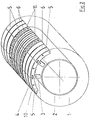
- the roller grate according to the invention is made up of a plurality of grate rollers 1 arranged one behind the other in steps.
- Each grate roller 1 consists of a drivable hollow shaft 2 in the form of a horizontal cylinder, on the circumferential surface of which holders 3 for grate bar supports 4 are fastened.
- Central grate bars 5 are suspended transversely between the grate bar supports 4, which run in a straight line and at the same distance from one another parallel to the hollow shaft axis.
- the central grate bars 5 thus form the casing of the grate roller 1.
- the outer surfaces 9.1 of the central grate bars 5 run on parallel, circumferential circular paths (grate burn paths), between which there are air slots 6. ( Figure 1).
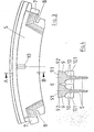
- the central grate bars 5 have a substantially T-shaped cross section, their longitudinal section essentially represents a circular section, the outer boundary line of which follows the circumference of the grate roller 1. ( Figure 3 and Figure 4).
- the outer surface 9.1 of a grate rod head 9 is smooth and flat, it forms part of the grate fire surface, and its side surfaces 9.2 are smooth and run in a straight line.
- the abutting side surfaces 9.2 two axially adjacent central grate bars 5 are kept at a distance by spacers 10, which are located on both sides on the long sides of the central grate bars 5; this creates the air slot 6 between them.
- the abutting surfaces 10.1 of the spacers 10 are smooth and flat.
- the circumferential grate combustion tracks are formed by fixed-point rods 11 (FIG. 1), which are screwed onto the grate rod support 4 instead of the suspended central grate rods 5. You lock the central grate bars 5, and since the grate bar supports 4 are interrupted in the area of the fixed point bars 11, the grate roller 1 is divided into segments.
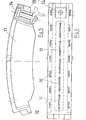
- the fixed point rods 11 are also curved in the longitudinal direction according to the circumference of the grate roller 1 (FIG. 5). On the front side they have a projection 12 which, after assembly, fits into a corresponding recess 13 at the foot end of the radially adjacent fixed point rod 11. The fit extends over the entire width of the fixed point rod 11, so there are no continuous vertical gaps at the transition point between two fixed point rods 11. In this way, the fit is secured against the passage of liquid metals.
- the focal surface 15 of the fixed point rods 11 additionally has openings 16 for the combustion air.
- grate bars 5 of different widths when building up a grate roller, e.g. narrower central grate bars in the central area of the grate roller than in their edge areas (FIG. 2), the supply of the combustion air into the fuel bed can be specifically controlled transversely to the transport direction. It is also possible to provide the individual grate rollers 1 of a roller grate with differently structured grate coverings in order to additionally optimize the combustion air supply in the direction of transport of the waste.
- the individual grate rollers 1 rotate in the direction of descent.
- the waste is added to the top grate roller 1, it is transported and circulated during the combustion.
- the combustion air flows axially into the grate rollers 1 and exits radially through the air slots 6 and the openings 16 in the fixed-point rods 11 on the upper side (combustion chamber side).
- a good heat transfer is guaranteed by the large surface area of the cooling fins, so that the central grate bars 5 are adequately cooled even with a high proportion of bulky waste. Due to the lower temperature of the grate during combustion, the wear is significantly reduced and the service life of the grate bars is extended considerably.
- the grate rollers 1 are loaded differently over their axial length. This leads to relative movements of the central grate bars 5 against one another along the grate combustion tracks. Clogging of the air slots 6 by baking metals is prevented.
- the fixed point rods 11 can be loosened from the combustion chamber side.
- the suspended central grate bars 5 can then simply be pulled out and replaced. This leads to a significant reduction in the downtime of the roller grate caused by repairs to the grate covering.
Abstract
Description
Die Erfindung betrifft ein Walzenrost gemäß dem Oberbegriff des Patentanspruchs 1.The invention relates to a roller grate according to the preamble of
Walzenroste werden in Müllverbrennungsanlagen insbesondere zur Verbrennung von festen Abfällen, z.B. Hausmüll, eingesetzt. Ein Walzenrost besteht aus mehreren stufenförmig unmittelbar hintereinander angeordneten Rostwalzen, die langsam und gleichsinnig rotieren. Der Müll wird auf die oberste Rostwalze aufgegeben, durch die Drehung der Rostwalzen wird er während der Verbrennung weitertransportiert und umgewälzt.Roller grates are used in waste incineration plants, in particular for the combustion of solid waste, e.g. Household waste, used. A roller grate consists of several grate rollers that are arranged in steps one behind the other and rotate slowly and in the same direction. The garbage is placed on the top grate roller, the rotation of the grate rollers means that it is transported and circulated during combustion.
Die Rostwalzen sind auf ihrem Umfang mit Roststäben belegt, zwischen denen sich Luftschlitze für die Verbrennungsluft befinden. Diese wird üblicherweise axial in die Rostwalzen eingeleitet und tritt anschließend auf der Feuerraumseite radial durch die Luftschlitze aus. Sie dient so gleichzeitig als Kühlluft für die Roststäbe.The grate rollers are covered on their circumference with grate bars, between which there are air slots for the combustion air. This is usually introduced axially into the grate rollers and then emerges radially through the air slots on the combustion chamber side. It also serves as cooling air for the grate bars.
Im allgemeinen werden zur Belegung verschieden ausgeführte Roststäbe verwendet: Der überwiegende Teil der Rostfläche wird von zwischen Roststabträgern eingehängten Mittelroststäben gebildet, diese sind segmentweise mit Festpunktstäben arretiert, die von der Walzeninnenseite her an den Roststabträgern festgeschraubt sind.In general, differently designed grate bars are used for covering: The majority of the grate surface is formed by middle grate bars suspended between grate bar supports, which are locked in segments with fixed point bars that are screwed onto the grate bar supports from the inside of the roller.
Im Betrieb sind die Roststäbe starken Belastungen ausgesetzt, daher unterliegen sie einem hohen Verschleiß, dessen Höhe mit der Temperatur der Roststäbe unverhältnismäßig stark zunimmt. Darüber hinaus lassen sich gelegentliche mechanische Beschädigungen der Roststäbe durch Bestandteile des Mülls nicht vermeiden. Verschleiß und Beschädigungen erzwingen einen regelmäßigen (gegebenenfalls auch unregelmäßigen) Austausch der Roststäbe.The grate bars are exposed to heavy loads during operation, which is why they are subject to high wear, the height of which increases disproportionately with the temperature of the grate bars. In addition, occasional mechanical damage to the grate bars from components of the waste cannot be avoided. Wear and damage force the grate bars to be replaced regularly (possibly also irregularly).
Zusätzlich verringern Störungen durch leicht schmelzbare Metalle(z.B. Aluminium, Zinn, Zink), die im Müll vorhanden sind, die Standzeiten der Roststäbe ganz erheblich. Während der Verbrennung aufgeschmolzen, fließen diese Metalle in die Luftschlitze zwischen den Mittelroststäben, wo sie von der Verbrennungsluft abgekühlt werden und erstarren. Dadurch entstehen in den Luftschlitzen Anbackungen, die diese allmählich zusetzen. Treten dadurch Störungen in der Verbrennungsluftzufuhr auf, so ist man gezwungen, den verstopften Teil des Rostbelags komplett zu erneuern.In addition, faults caused by easily meltable metals (e.g. aluminum, tin, zinc) that are present in the waste significantly reduce the service life of the grate bars. When molten, these metals flow into the air slots between the central grate bars, where they are cooled by the combustion air and solidify. This creates caking in the louvers, which gradually clog them. If this causes malfunctions in the combustion air supply, you are forced to replace the clogged part of the grate completely.
Ein gattungsgemäßes Walzenrost ist in der DE-PS 11 64 014 beschrieben. Das Walzenrost besteht aus Rostwalzen mit Inneneinbauten, durch die die durchtropfenden Metalle im Innern der Rostwalze aufgefangen werden. Man will so eine Verstopfung der Luftschlitze auf der dem Feuerraum abgewandten Seite verhindern. Es wird kein Hinweis gegeben, wie das Verstopfen der Luftschlitze auf der Feuerraumseite verhindert werden kann.A generic roller grate is described in DE-PS 11 64 014. The roller grate consists of grate rollers with internals, through which the dripping metals are caught inside the grate roller. The aim is to prevent the air slots on the side facing away from the combustion chamber from becoming blocked. No information is given on how to prevent the clogging of the air slots on the combustion chamber side.
Durch die US-PS 3 469 544 ist eine Rostwalze bekannt, die mit unterschiedlichen Mittelroststäben belegt ist. Neben Mittelroststäben, deren Köpfe seitlich verzahnt oder wellenförmig ausgebildet sind, werden an den axialen Rändern der Rostwalzen auch solche mit gerade verlaufenden Seiten verwendet. Es wird nicht gezeigt, wie die Mittelroststäbe auf der Walze befestigt sind. Das angeführte Beispiel eines Mittelroststabes hat gezahnte Roststabseiten und keine Abstandshalter.A grate roller is known from US Pat. No. 3,469,544, which is covered with different central grate bars. In addition to central grate bars, the heads of which are laterally toothed or wave-shaped, those with straight sides are also used on the axial edges of the grate rollers. It is not shown how the central grate bars are attached to the roller. The example of a central grate bar has serrated grate bars and no spacers.
Der Erfindung liegt die Aufgabe zugrunde, die durch Reparaturarbeiten an den Rostwalzenbelägen erzwungenen Stillstandszeiten des Walzenrostes zu verkürzen.The invention has for its object to shorten the downtime of the roller grate forced by repair work on the grate roller coverings.
Diese Aufgabe wird durch die kennzeichnenden Merkmale des Patentanspruchs 1 gelöst.This object is achieved by the characterizing features of
Durch das Spiel zwischen Roststabträger und dem Fuß des Mittelroststabes und durch die glatten und ebenen Stoßflächen der Abstandshalter führen die Mittelroststäbe während des Betriebs Relativbewegungen in Längsrichtung gegeneinander aus. Dadurch werden Verstopfungen der Luftschlitze zwischen den Roststäben durch Anbackungen verhindert.Due to the play between the grate bar support and the base of the central grate bar and due to the smooth and flat abutting surfaces of the spacers, the central grate bars execute relative movements in the longitudinal direction against one another during operation. This prevents clogging of the air slots between the grate bars due to caking.
Das Merkmal des Anspruchs 2 führt zu einer besseren Kühlung der Mittelroststäbe mit günstigen Auswirkungen auf den Verschleiß.The feature of
Durch das Merkmal des Anspruchs 3 läßt sich dem Brennstoffbett die Verbrennungsluft gezielt und gleichmäßig zuführen.Due to the feature of
Das Merkmal des Anspruchs 4 ermöglicht ein schnelles und einfaches Auswechseln der Roststäbe von der Feuerraumseite.The feature of
Durch das Merkmal des Anspruchs 5 wird die Verbrennungsluftzufuhr im Bereich der Festpunktstäbe nicht unterbrochen.Due to the feature of
Das Merkmal des Anspruchs 6 verhindert ein Durchfließen von flüssigen Metallen in das Innere der Rostwalze.The feature of
Die Ansprüche 4 - 6 sind selbständige Nebenansprüche, ihre Merkmale sind auch bei Walzenrosten, die nicht die Merkmale des Patentanspruchs 1 aufweisen, mit Vorteil verwendbar.Claims 4-6 are independent subsidiary claims, their characteristics can also be used with advantage in the case of roller grates which do not have the characteristics of
Die Zeichnung dient zur Erläuterung der Erfindung.
Figur 1 zeigt grob schematisch den Ausschnitt einer Rostwalze mit Mittelroststäben gleicher Breite.Figur 2 zeigt grob schematisch einen Ausschnitt einer Rostwalze mit unterschiedlichen Breiten der Mittelroststäbe.Figur 3 zeigt die Ansicht eines Mittelroststabes.Figur 4 zeigt einen Schnitt entlang der Linie A-B vonFigur 3.Figur 5 undFigur 6 zeigen An- und Aufsicht eines Festpunktstabes.
- Figure 1 shows a rough schematic of the section of a grate roller with central grate bars of the same width.
- Figure 2 shows roughly schematically a section of a grate roller with different widths of the central grate bars.
- Figure 3 shows the view of a central grate bar.
- FIG. 4 shows a section along the line AB from FIG. 3.
- Figure 5 and Figure 6 show the view and supervision of a fixed point rod.
Das erfindungsgemäße Walzenrost baut sich aus mehreren stufenförmig hintereinander angeordneten Rostwalzen 1 auf. Jede Rostwalze 1 besteht aus einer antreibbaren Hohlwelle 2 in Form eines waagrechten Zylinders, auf dessen Mantelfläche umlaufend Halterungen 3 für Roststabträger 4 befestigt sind. Quer zwischen den Roststabträgern 4, die gradlinig und mit gleichem Abstand voneinander parallel zur Hohlwellenachse verlaufen, sind Mittelroststäbe 5 eingehängt.The roller grate according to the invention is made up of a plurality of
Die Mittelroststäbe 5 bilden so die Ummantelung der Rostwalze 1. Die Außenflächen 9.1 der Mittelroststäbe 5 verlaufen dabei auf parallelen, umlaufenden Kreisbahnen (Rostbrennbahnen), zwischen denen sich Luftschlitze 6 befinden. (Figur 1).The
Die Mittelroststäbe 5 haben im wesentlichen T-förmigen Querschnitt, ihr Längsschnitt stellt im wesentlichen einen Kreisringausschnitt dar, dessen äußere Begrenzungslinie dem Umfang der Rostwalze 1 folgt. (Figur 3 und Figur 4).The
An den Enden der Mittelroststäbe 5 (= Roststabfüße 7) sind Aussparungen 8, in die die Röststabträger 4 eingreifen. Die Außenfläche 9.1 eines Roststabkopfes 9 ist glatt und eben, - sie bildet einen Teil der Rostbrandfläche -, und seine Seitenflächen9.2 sind glatt und verlaufen gradlinig. Die aneinander stoßenden Seitenflächen 9.2 zweir axial benachberter Mittelroststäbe 5 werden von Abstandshaltern 10, die sich beidseitig an den Längsseiten der Mittelroststäbe 5 befinden, auf Abstand gehalten; so entsteht zwischen ihnen der Luftschlitz 6. Die Stoßflächen 10.1 der Abstandshalter 10 sind glatt und.eben. Die Kühlrippenoberfläche des Mittelroststabes 5, das ist der Teil seiner Oberfläche, an dem die Verbrennungsluft auf dem Weg zum Brennstoffbett vorbeistreicht, also die unverdeckte Oberfläche im Innern der Rostwalze 1, beträgt mindestens das 8-fache seiner Brennbahnfläche (= Außenfläche 9.1).At the ends of the central grate bars 5 (= grate bar feet 7) there are
In regelmäßigen axialen Abständen werden die umlaufenden Rostbrennbahnen von Festpunktstäben 11 gebildet (Figur 1), die anstelle der eingehängten Mittelroststäbe 5 am Roststabträger 4 festgeschraubt sind. Sie arretieren die Mittelroststäbe 5, und da die Roststabträger 4 im Bereich der Festpunktstäbe 11 unterbrochen sind, wird die Rostwalze 1 so in Segmente aufgeteilt.At regular axial intervals, the circumferential grate combustion tracks are formed by fixed-point rods 11 (FIG. 1), which are screwed onto the
Die Festpunktstäbe 11 sind in Längsrichtung ebenfalls entsprechend dem Umfang der Rostwalze 1 gekrümmt (Figur 5). An der Stirnseite haben sie einen Vorsprung 12, der nach der Montage in eine entsprechende Aussparung 13 am Fußende des radial benachbarten Festpunktstabes 11 einpaßt. Die Einpassung erstreckt sich über die ganze Breite des Festpunktstabes 11, so treten keine durchgehenden vertikalen Spalte an der Übergangstelle zwischen zwei Festpunktstäben 11 auf. So wird die Einpassung gegen das Durchlaufen von flüssigen Metallen abgesichert. Die Brennfläche 15 der Festpunktstäbe 11 weist zusätzlich Öffnungen 16 für die Verbrennungsluft auf.The
Es ist möglich, beim Aufbau einer Rostwalze 1 Roststäbe 5 unterschiedlicher Breite zu verwenden, z.B. schmalere Mittelroststäbe im mittleren Bereich der Rostwalze als in ihren Randbereichen (Figur 2), so läßt sich die Zuführung der Verbrennungsluft in das Brennstoffbett quer zur Transportrichtung gezielt steuern. Ebenso ist es möglich, die einzelnen Rostwalzen 1 eines Walzenrostes mit unterschiedlich aufgebauten Rostbelägen zu versehen, um zusätzlich die Verbrennungsluftzuführung in Transportrichtung des Mülls zu optimieren.It is possible to use 1
Im Betrieb rotieren die einzelnen Rostwalzen 1 in Richtung des Abstiegs. Der Müll wird der obersten Rostwalze 1 zugegeben, er wird während der Verbrennung weitertransportiert und umgewälzt. Die Verbrennungsluft strömt axial in die Rostwalzen 1 ein und tritt radial durch die Luftschlitze 6 und die Öffnungen 16 in den Festpunktstäben 11 auf der oberen Seite (Feuerraumseite) aus. Auf dem Weg streift sie an den Kühlrippen der Mittelroststäbe 5 vorbei, kühlt diese ab und erwärmt sich. Durch die große Kühlrippenoberfläche ist ein guter Wärmeübergang garantiert, so daß auch bei hohem Sperrmüllanteil die Mittelroststäbe 5 ausreichend gekühlt werden. Durch die so erreichte geringere Temperatur des Rostbelags während der Verbrennung wird der Verschleiß wesentlich verringert, und damit verlängern sich die Standzeiten der Roststäbe erheblich.In operation, the
Während des Betriebs werden die Rostwalzen 1 über ihre axiale Länge unterschiedlich belastet. Dies führt zu Relativbewegungen der Mittelroststäbe 5 entlang der Rostbrennbahnen gegeneinander. So wird ein Verstopfen der Luftschlitze 6 durch anbackende Metalle verhindert.During operation, the
Zum Auswechseln, bei Beschädigungen oder routinemäßig infolge des Verschleißes, lassen sich die Festpunktstäbe 11 von der Feuerraumseite her lösen. Die eingehängten Mittelroststäbe 5 können anschließend einfach herausgezogen und ersetzt werden. Das führt zu einer wesentlichen Verkürzung der durch Reparaturen am Rostbelag bedingten Stillstandszeiten des Walzenrostes.For replacement, damage or routinely as a result of wear, the fixed
Claims (6)
dadurch gekennzeichnet,
characterized,
Priority Applications (1)
| Application Number | Priority Date | Filing Date | Title |
|---|---|---|---|
| AT84104631T ATE28504T1 (en) | 1983-05-05 | 1984-04-25 | ROLLER GRATE FOR WASTE INCINERATION PLANTS. |
Applications Claiming Priority (2)
| Application Number | Priority Date | Filing Date | Title |
|---|---|---|---|
| DE3316363 | 1983-05-05 | ||
| DE3316363A DE3316363A1 (en) | 1983-05-05 | 1983-05-05 | ROLLER GRID FOR WASTE COMBUSTION PLANTS |
Publications (3)
| Publication Number | Publication Date |
|---|---|
| EP0124826A2 true EP0124826A2 (en) | 1984-11-14 |
| EP0124826A3 EP0124826A3 (en) | 1985-05-29 |
| EP0124826B1 EP0124826B1 (en) | 1987-07-22 |
Family
ID=6198185
Family Applications (1)
| Application Number | Title | Priority Date | Filing Date |
|---|---|---|---|
| EP84104631A Expired EP0124826B1 (en) | 1983-05-05 | 1984-04-25 | Cylindrical grate for incinerators |
Country Status (4)
| Country | Link |
|---|---|
| US (1) | US4537139A (en) |
| EP (1) | EP0124826B1 (en) |
| AT (1) | ATE28504T1 (en) |
| DE (2) | DE3316363A1 (en) |
Cited By (13)
| Publication number | Priority date | Publication date | Assignee | Title |
|---|---|---|---|---|
| EP0399898A1 (en) * | 1989-05-25 | 1990-11-28 | Tunzini Picard Thermique Environnement | Roll for a furnace roller grate, especially for burning waste, with a tubular lining formed by annular grate bars separated between them by air gaps of constant width |
| DE4300636C1 (en) * | 1993-01-13 | 1994-07-14 | Rbu Rolf Becker Gmbh Ingieneur | Roller grate for operating a combustion boiler |
| EP2113718A2 (en) | 2008-04-28 | 2009-11-04 | Vinci Environnement | Cylindrical combustion grate for a furnace with a cooling system |
| WO2011003820A1 (en) | 2009-07-06 | 2011-01-13 | Sanofi-Aventis Deutschland Gmbh | Heat- and vibration-stable insulin preparations |
| WO2011003822A2 (en) | 2009-07-06 | 2011-01-13 | Sanofi-Aventis Deutschland Gmbh | Insulin preparations containing methionine |
| WO2011003823A1 (en) | 2009-07-06 | 2011-01-13 | Sanofi-Aventis Deutschland Gmbh | Slow-acting insulin preparations |
| EP2289539A1 (en) | 2001-03-23 | 2011-03-02 | Sanofi-Aventis Deutschland GmbH | Zinc-free and low-zinc insulin preparations with improved stability |
| EP2305288A2 (en) | 2002-06-18 | 2011-04-06 | Sanofi-Aventis Deutschland GmbH | Acidic insulin preparations with improved stability |
| WO2014096985A2 (en) | 2012-12-19 | 2014-06-26 | Wockhardt Limited | A stable aqueous composition comprising human insulin or an analogue or derivative thereof |
| WO2014102623A1 (en) | 2012-12-26 | 2014-07-03 | Wockhardt Limited | Pharmaceutical composition |
| WO2015044922A1 (en) | 2013-09-30 | 2015-04-02 | Wockhardt Limited | Pharmaceutical composition |
| WO2016001862A1 (en) | 2014-07-04 | 2016-01-07 | Wockhardt Limited | Extended release formulations of insulins |
| US9707176B2 (en) | 2009-11-13 | 2017-07-18 | Sanofi-Aventis Deutschland Gmbh | Pharmaceutical composition comprising a GLP-1 agonist and methionine |
Families Citing this family (8)
| Publication number | Priority date | Publication date | Assignee | Title |
|---|---|---|---|---|
| DE3341835A1 (en) * | 1983-11-19 | 1985-05-30 | Deutsche Babcock Anlagen Ag, 4200 Oberhausen | Grate lining for furnace grates with revolving grate combustion paths |
| DE59005994D1 (en) * | 1989-05-10 | 1994-07-14 | Babcock Anlagen Ag | Grate bar and grate roller. |
| EP0981021A1 (en) * | 1998-08-19 | 2000-02-23 | Asea Brown Boveri AG | Grate for incinerators |
| AT410128B (en) * | 2000-11-08 | 2003-02-25 | Ferdinand Dipl Ing Tischler | RUST FOR SOLID FUELS |
| DE102004011834A1 (en) | 2004-03-09 | 2005-10-06 | Fisia Babcock Environment Gmbh | roller grate |
| CH697973B1 (en) * | 2005-06-10 | 2009-04-15 | Alstom Technology Ltd | Grate roller. |
| DE102007033825B4 (en) * | 2007-07-18 | 2021-05-20 | Nippon Steel & Sumikin Engineering Co., Ltd. | Roller grate with hydraulic drive and a method for operating the roller grate |
| PL232801B1 (en) * | 2017-03-14 | 2019-07-31 | Pellasx Spolka Z Ograniczona Odpowiedzialnoscia Spolka Komandytowa | Combustion chamber burner grate for combustion of pellets and other solid fuels |
Citations (3)
| Publication number | Priority date | Publication date | Assignee | Title |
|---|---|---|---|---|
| DE206353C (en) * | ||||
| GB191209555A (en) * | 1912-04-23 | 1913-03-27 | Joseph Ernst Fletcher | Improvements in Furnace Grates. |
| FR1214713A (en) * | 1958-02-01 | 1960-04-11 | Metallgesellschaft Ag | Construction of grid bars |
Family Cites Families (6)
| Publication number | Priority date | Publication date | Assignee | Title |
|---|---|---|---|---|
| US1831816A (en) * | 1929-10-26 | 1931-11-17 | Charles B Magrath | Heating device |
| US2501763A (en) * | 1945-03-26 | 1950-03-28 | Charles T Denker | Solid fuel furnace of the rotary grate progressive feed type |
| DE1164014B (en) * | 1962-05-25 | 1964-02-27 | Ver Kesselwerke Ag | Grate roller for roller grate for waste incineration |
| DE1260665B (en) * | 1967-05-23 | 1968-02-08 | Ver Kesselwerke Ag | Grate covering for the grate rollers of a roller grate in waste incineration plants |
| DE2839536C3 (en) * | 1978-09-11 | 1981-10-15 | Rheinische Eisengießerei Wilhelm Pulch KG, 4030 Ratingen | Grate bar for roller grates in an incineration plant |
| CH637198A5 (en) * | 1979-03-14 | 1983-07-15 | Widmer & Ernst Ag | BURNING GRATE FOR COMBUSTION OVENS. |
-
1983
- 1983-05-05 DE DE3316363A patent/DE3316363A1/en active Granted
-
1984
- 1984-04-25 AT AT84104631T patent/ATE28504T1/en not_active IP Right Cessation
- 1984-04-25 DE DE8484104631T patent/DE3464956D1/en not_active Expired
- 1984-04-25 EP EP84104631A patent/EP0124826B1/en not_active Expired
- 1984-05-03 US US06/608,022 patent/US4537139A/en not_active Expired - Lifetime
Patent Citations (3)
| Publication number | Priority date | Publication date | Assignee | Title |
|---|---|---|---|---|
| DE206353C (en) * | ||||
| GB191209555A (en) * | 1912-04-23 | 1913-03-27 | Joseph Ernst Fletcher | Improvements in Furnace Grates. |
| FR1214713A (en) * | 1958-02-01 | 1960-04-11 | Metallgesellschaft Ag | Construction of grid bars |
Cited By (16)
| Publication number | Priority date | Publication date | Assignee | Title |
|---|---|---|---|---|
| FR2647532A1 (en) * | 1989-05-25 | 1990-11-30 | Picard Fours | FIREPLACE ROLL, IN PARTICULAR FOR WASTE INCINERATION, WITH TUBULAR TRIM FORMED BY RINGS OF BARS SEPARATED BY MAINTAINED WIDTH BLOWING INTERVALS |
| US5057011A (en) * | 1989-05-25 | 1991-10-15 | Fours Picard | Furnace grate roller namely for incinerating refuse with a tubular casing formed by rings of bars separated by blow gaps of set width |
| EP0399898A1 (en) * | 1989-05-25 | 1990-11-28 | Tunzini Picard Thermique Environnement | Roll for a furnace roller grate, especially for burning waste, with a tubular lining formed by annular grate bars separated between them by air gaps of constant width |
| DE4300636C1 (en) * | 1993-01-13 | 1994-07-14 | Rbu Rolf Becker Gmbh Ingieneur | Roller grate for operating a combustion boiler |
| EP2289539A1 (en) | 2001-03-23 | 2011-03-02 | Sanofi-Aventis Deutschland GmbH | Zinc-free and low-zinc insulin preparations with improved stability |
| EP2305288A2 (en) | 2002-06-18 | 2011-04-06 | Sanofi-Aventis Deutschland GmbH | Acidic insulin preparations with improved stability |
| EP2113718A2 (en) | 2008-04-28 | 2009-11-04 | Vinci Environnement | Cylindrical combustion grate for a furnace with a cooling system |
| WO2011003823A1 (en) | 2009-07-06 | 2011-01-13 | Sanofi-Aventis Deutschland Gmbh | Slow-acting insulin preparations |
| WO2011003822A2 (en) | 2009-07-06 | 2011-01-13 | Sanofi-Aventis Deutschland Gmbh | Insulin preparations containing methionine |
| WO2011003820A1 (en) | 2009-07-06 | 2011-01-13 | Sanofi-Aventis Deutschland Gmbh | Heat- and vibration-stable insulin preparations |
| EP3202394A1 (en) | 2009-07-06 | 2017-08-09 | Sanofi-Aventis Deutschland GmbH | Aqueous preparations comprising methionine |
| US9707176B2 (en) | 2009-11-13 | 2017-07-18 | Sanofi-Aventis Deutschland Gmbh | Pharmaceutical composition comprising a GLP-1 agonist and methionine |
| WO2014096985A2 (en) | 2012-12-19 | 2014-06-26 | Wockhardt Limited | A stable aqueous composition comprising human insulin or an analogue or derivative thereof |
| WO2014102623A1 (en) | 2012-12-26 | 2014-07-03 | Wockhardt Limited | Pharmaceutical composition |
| WO2015044922A1 (en) | 2013-09-30 | 2015-04-02 | Wockhardt Limited | Pharmaceutical composition |
| WO2016001862A1 (en) | 2014-07-04 | 2016-01-07 | Wockhardt Limited | Extended release formulations of insulins |
Also Published As
| Publication number | Publication date |
|---|---|
| DE3316363C2 (en) | 1991-10-17 |
| DE3464956D1 (en) | 1987-08-27 |
| US4537139A (en) | 1985-08-27 |
| EP0124826B1 (en) | 1987-07-22 |
| EP0124826A3 (en) | 1985-05-29 |
| ATE28504T1 (en) | 1987-08-15 |
| DE3316363A1 (en) | 1984-11-08 |
Similar Documents
| Publication | Publication Date | Title |
|---|---|---|
| EP0124826B1 (en) | Cylindrical grate for incinerators | |
| EP0811818B1 (en) | Grate plate and its fabrication process | |
| EP0499912B1 (en) | Grate bar and grate for combustion plants | |
| EP0954722B1 (en) | Water-cooled firing grate | |
| EP0157920B1 (en) | Roll for a roller grate, for example for a refuse burning plant or the like | |
| EP0165432B1 (en) | Furnace, especially for the combustion of refuse, coal, wood and industrial waste | |
| DE3421365C1 (en) | Tunnel kiln | |
| EP0216346B1 (en) | Thermal-treating machine | |
| DE2604611A1 (en) | STEP-GRID COOLER, IN PARTICULAR FEED-STEP GRATE COOLER | |
| EP0012398A1 (en) | Rotary drum | |
| DE102009042722A1 (en) | grate bar | |
| DE19851471A1 (en) | Feed grate cover for combustion furnace has narrow S-shaped gaps to allow very little material to fall through and uses stair-step-type bars in close contact | |
| CH636178A5 (en) | RUST COATING, ESPECIALLY FOR LARGE FIREPLACES. | |
| DE3813441A1 (en) | Grating bar element for a thrust grating furnace for refuse incineration | |
| DE19537904A1 (en) | Heat-exchanger grid plate | |
| DE3322139A1 (en) | RUST COOLER | |
| DE19952198A1 (en) | Grating roller has axially parallel holders, outer casing, circle arc shaped bars, wide cylindrical heads, openings and side surfaces | |
| DE1164014B (en) | Grate roller for roller grate for waste incineration | |
| DE3341835C2 (en) | ||
| DE19907944A1 (en) | Heating plate for tunnel furnace, especially for burning refuse, has air passages in its end wall and cooling ribs parallel to side walls on underside | |
| EP0606551B2 (en) | Roller grate for a combustion boiler | |
| DE1526051C2 (en) | Liquid-cooled moving grate for burning slimes | |
| EP4302037A1 (en) | Rotary kiln and method for burning carbonate-containing material, more particularly limestone or dolomite | |
| DE687125C (en) | Drying drum with trickle fittings | |
| EP0786637A1 (en) | Sliding grate for the treatment of bulk material |
Legal Events
| Date | Code | Title | Description |
|---|---|---|---|
| PUAI | Public reference made under article 153(3) epc to a published international application that has entered the european phase |
Free format text: ORIGINAL CODE: 0009012 |
|
| AK | Designated contracting states |
Designated state(s): AT BE CH DE FR GB IT LI LU NL SE |
|
| PUAL | Search report despatched |
Free format text: ORIGINAL CODE: 0009013 |
|
| AK | Designated contracting states |
Designated state(s): AT BE CH DE FR GB IT LI LU NL SE |
|
| 17P | Request for examination filed |
Effective date: 19850625 |
|
| 17Q | First examination report despatched |
Effective date: 19860206 |
|
| ITF | It: translation for a ep patent filed |
Owner name: DE DOMINICIS & MAYER S.R.L. |
|
| GRAA | (expected) grant |
Free format text: ORIGINAL CODE: 0009210 |
|
| AK | Designated contracting states |
Kind code of ref document: B1 Designated state(s): AT BE CH DE FR GB IT LI LU NL SE |
|
| REF | Corresponds to: |
Ref document number: 28504 Country of ref document: AT Date of ref document: 19870815 Kind code of ref document: T |
|
| REF | Corresponds to: |
Ref document number: 3464956 Country of ref document: DE Date of ref document: 19870827 |
|
| ET | Fr: translation filed | ||
| PG25 | Lapsed in a contracting state [announced via postgrant information from national office to epo] |
Ref country code: LU Free format text: LAPSE BECAUSE OF NON-PAYMENT OF DUE FEES Effective date: 19880430 |
|
| PLBI | Opposition filed |
Free format text: ORIGINAL CODE: 0009260 |
|
| 26 | Opposition filed |
Opponent name: MUELLVERBRENNUNGSANLAGE WUPPERTAL GMBH Effective date: 19880121 |
|
| NLR1 | Nl: opposition has been filed with the epo |
Opponent name: MUELLVERBRENNUNGSANLAGE WUPPERTAL GMBH |
|
| PGFP | Annual fee paid to national office [announced via postgrant information from national office to epo] |
Ref country code: BE Payment date: 19900109 Year of fee payment: 7 |
|
| PGFP | Annual fee paid to national office [announced via postgrant information from national office to epo] |
Ref country code: LU Payment date: 19900216 Year of fee payment: 7 |
|
| PGFP | Annual fee paid to national office [announced via postgrant information from national office to epo] |
Ref country code: AT Payment date: 19900219 Year of fee payment: 7 |
|
| PGFP | Annual fee paid to national office [announced via postgrant information from national office to epo] |
Ref country code: CH Payment date: 19900220 Year of fee payment: 7 |
|
| PGFP | Annual fee paid to national office [announced via postgrant information from national office to epo] |
Ref country code: FR Payment date: 19900302 Year of fee payment: 7 |
|
| PGFP | Annual fee paid to national office [announced via postgrant information from national office to epo] |
Ref country code: DE Payment date: 19900410 Year of fee payment: 7 |
|
| PGFP | Annual fee paid to national office [announced via postgrant information from national office to epo] |
Ref country code: SE Payment date: 19900412 Year of fee payment: 7 |
|
| PGFP | Annual fee paid to national office [announced via postgrant information from national office to epo] |
Ref country code: GB Payment date: 19900417 Year of fee payment: 7 |
|
| ITTA | It: last paid annual fee | ||
| PGFP | Annual fee paid to national office [announced via postgrant information from national office to epo] |
Ref country code: NL Payment date: 19900430 Year of fee payment: 7 |
|
| RDAG | Patent revoked |
Free format text: ORIGINAL CODE: 0009271 |
|
| STAA | Information on the status of an ep patent application or granted ep patent |
Free format text: STATUS: PATENT REVOKED |
|
| GBPR | Gb: patent revoked under art. 102 of the ep convention designating the uk as contracting state | ||
| REG | Reference to a national code |
Ref country code: CH Ref legal event code: PL |
|
| 27W | Patent revoked |
Effective date: 19900329 |
|
| NLR2 | Nl: decision of opposition | ||
| BERE | Be: lapsed |
Owner name: DEUTSCHE BABCOCK ANLAGEN A.G. Effective date: 19910430 |
|
| EUG | Se: european patent has lapsed |
Ref document number: 84104631.1 Effective date: 19900816 |