EP2112020A1 - Headlamp assembly and vehicle - Google Patents
Headlamp assembly and vehicle Download PDFInfo
- Publication number
- EP2112020A1 EP2112020A1 EP08155097A EP08155097A EP2112020A1 EP 2112020 A1 EP2112020 A1 EP 2112020A1 EP 08155097 A EP08155097 A EP 08155097A EP 08155097 A EP08155097 A EP 08155097A EP 2112020 A1 EP2112020 A1 EP 2112020A1
- Authority
- EP
- European Patent Office
- Prior art keywords
- lens
- headlamp assembly
- protrusion
- vehicle
- headlamp
- Prior art date
- Legal status (The legal status is an assumption and is not a legal conclusion. Google has not performed a legal analysis and makes no representation as to the accuracy of the status listed.)
- Granted
Links
Images

Classifications
-
- B—PERFORMING OPERATIONS; TRANSPORTING
- B60—VEHICLES IN GENERAL
- B60Q—ARRANGEMENT OF SIGNALLING OR LIGHTING DEVICES, THE MOUNTING OR SUPPORTING THEREOF OR CIRCUITS THEREFOR, FOR VEHICLES IN GENERAL
- B60Q1/00—Arrangement of optical signalling or lighting devices, the mounting or supporting thereof or circuits therefor
- B60Q1/02—Arrangement of optical signalling or lighting devices, the mounting or supporting thereof or circuits therefor the devices being primarily intended to illuminate the way ahead or to illuminate other areas of way or environments
- B60Q1/04—Arrangement of optical signalling or lighting devices, the mounting or supporting thereof or circuits therefor the devices being primarily intended to illuminate the way ahead or to illuminate other areas of way or environments the devices being headlights
- B60Q1/0491—Shock absorbing devices therefor
-
- B—PERFORMING OPERATIONS; TRANSPORTING
- B62—LAND VEHICLES FOR TRAVELLING OTHERWISE THAN ON RAILS
- B62D—MOTOR VEHICLES; TRAILERS
- B62D25/00—Superstructure or monocoque structure sub-units; Parts or details thereof not otherwise provided for
- B62D25/08—Front or rear portions
- B62D25/10—Bonnets or lids, e.g. for trucks, tractors, busses, work vehicles
- B62D25/12—Parts or details thereof
-
- F—MECHANICAL ENGINEERING; LIGHTING; HEATING; WEAPONS; BLASTING
- F21—LIGHTING
- F21S—NON-PORTABLE LIGHTING DEVICES; SYSTEMS THEREOF; VEHICLE LIGHTING DEVICES SPECIALLY ADAPTED FOR VEHICLE EXTERIORS
- F21S45/00—Arrangements within vehicle lighting devices specially adapted for vehicle exteriors, for purposes other than emission or distribution of light
- F21S45/10—Protection of lighting devices
Definitions
- the present invention concerns a headlamp assembly for a vehicle and a vehicle comprising such a headlamp assembly.
- a headlamp is a lamp that is usually attached to the front of a vehicle, such a car, with the purpose of illuminating the road ahead during periods of low visibility, such as during the night or in bad weather conditions and/or to increase the conspicuity of vehicles in motion during the daytime.
- Headlamps usually comprise a light source, a reflector and a cover with a front surface forming a lens and are positioned in pairs, one or more on each side of the front of a vehicle.
- Some headlamps are designed so that the risk of injuries to a pedestrian is reduced in the event of a collision with a pedestrian.
- German patent application no. DE 102006007449 describes a headlamp that is attached to a carrying element, whereby the headlamp and the carrying element are separated by a gap in order to facilitate the adjustment of the position of the headlamp.
- the headlamp unit In case of a collision with a pedestrian, the headlamp unit is pushed into the gap towards the carrying element. Small segments protruding at a right angle from the surface of the carrying element create indents in the rear of the headlamp housing resulting in a reduction of the forces of the impact.
- European patent no. EP 1 120 309 concerns a headlamp housing that has a front light output opening covered by a lamp glass.
- the headlamp housing has a side section that extends inwards from the light output opening and has at least one rupture point, i.e. a mechanically weakened deformable portion, designed for absorbing the force upon impact with a pedestrian.
- Parts of the headlamp housing on either side of the rupture point are arranged to be telescopically inter-fitting. Since such an arrangement leads to a local deformation only in the area of rupture point(s), the energy absorption of the headlamp is limited by the maximum possible deformation in the area of the rupture point(s).
- An object of the present invention is to provide an improved headlamp assembly comprising a housing and a lens for a vehicle, and more particularly to provide a pedestrian-friendly headlamp assembly whereby the risk of injuries to a pedestrian is reduced in the event of a collision with a pedestrian.
- human as used in this document is intended to mean a human being or other living creature, and includes human beings using a vehicle, such as a bicycle or a motorbike, and is not therefore restricted to human beings moving on foot.
- headlamp assembly that comprises at least one protrusion that is arranged to be pushed into the lens, or whereby the lens is arranged to be pushed against the at least one protrusion, to initiate controlled deformation and/or breakage of the lens if/when the headlamp assembly is subjected to an impact or compression force in the event of a collision.
- a stress concentration will occur at the point at which the at least one protrusion contacts the lens, which will result in the deformation/breakage of the lens if the impact force exceeds a predetermined magnitude.
- the headlamp assembly therefore comprises at least one passive trigger to initiate controlled deformation and/or breakage of the lens since the present invention is based on the insight that a headlamp lens contributes to pedestrian injury during impacts and that the energy-absorbing capacity of a headlamp assembly can be increased by triggering the deformation/breakage of its lens.
- the force exerted by the lens on a pedestrian in the event of a collision will be reduced, which may reduce the number of injuries suffered by a pedestrian or the severity of the injuries.
- the deformation/breakage of the lens will result in a smoother impact because of a low force level during initial impact and high energy absorption due to the high deformation/breakage of the lens.
- the headlamp assembly gives a designer maximum freedom to achieve an optimum design with regard to pedestrian protection with a very minor need for additional components and manufacturing efforts.
- a further advantage is that since the lens is arranged to be deformed/broken rather than to be kept intact and displaced rearwards with or without the whole headlamp assembly, no substantial additional space behind the lens or headlamp assembly is necessarily required.
- the at least one protrusion and the lens may for example be arranged to be placed in contact with each other during the manufacture, installation or use of the headlamp assembly, or the at least one protrusion may be arranged to be placed within a distance of up to 5 mm for example from a surface of the lens, whereby the lens and/or protrusion are arranged to be displaced through small distance in the event of a collision with a pedestrian.
- lens as used in this document is intended to mean a piece of transparent or semi-transparent material, which is optionally used to focus rays of light, i.e. the lens may merely be a cover for a lamp or light source.
- the lens may be curved or substantially flat and be of any shape or form.
- a headlamp may be arranged to comprise a plurality of such lenses.
- a headlamp assembly may comprise a plurality of lamps or light sources and a single lens.
- deformation/breakage whether a lens deforms and/or breaks will depend on the physical properties of the material from which the lens is made and the magnitude of the impact/compression forces to which it is subjected in the event of a collision.
- the lens material and the design and location of the protrusions may be selected so as to achieve the desired deformation/breakage for a particular impact or compression force.
- controlled deformation/breakage is intended to mean that the headlamp assembly comprises at least one designated protrusion that is specifically provided to initiate the deformation/breakage of the lens.
- the at least one "protrusion” may be arranged to "protrude” only in the event of a collision.
- at least one protrusion may be arranged inside a plastically deformable material located between a headlamp housing and a lens for example, whereby the softer plastically deformable material is arranged to be displaced to reveal the at least one protrusion in the event of a collision.
- the at least one protrusion is provided on the housing. It should be noted that part of a vehicle comprising a headlamp assembly according to the present invention may constitute at least part of the headlamp assembly housing.
- the lens comprises at least one break line, i.e. at least one weakened area, such as an area of reduced thickness, in order to promote breakage of the lens in the at least one weakened area, whereby the at least one protrusion is arranged in the vicinity of the at least one break line.
- the lens comprises at least one groove that is arranged to receive the at least one protrusion if/when the headlamp assembly is subjected to an impact or compression force in the event of a collision
- the at least one groove and the at least one protrusion have a maximum extension, and the maximum extension of the at least one groove is smaller than the maximum extension of the at least one protrusion.
- the lens comprises a flange, such as a glue flange, and the at least one groove is provided on the flange.
- the lens comprises at least one continuous or non-continuous, uniform or non-uniform film, layer or coating that is arranged to prevent parts of a broken lens from being scattered if/when the headlamp assembly or the lens is subjected to an impact or compression force in the event of a collision resulting in breakage of the lens.
- the risk that a relatively sharp edge of the broken lens may injure the pedestrian, a person at the scene of the collision or a person repairing or replacing the headlamp assembly is thereby reduced.
- the lens comprises plastic or is made entirely of plastic.
- the present invention also concerns a lens that is suitable for use in a headlamp assembly according to the present invention.
- the present invention also concerns a vehicle that comprises a headlamp assembly or a lens according to any of the embodiments of the invention.
- the present invention is particularly, but not exclusively intended for use in passenger cars, trucks, buses, heavy goods vehicles or any other road-using vehicle or moving object.
- the present invention further concerns a vehicle comprising a headlamp assembly that comprises a housing and a lens, whereby the vehicle comprises a vehicle component, other than a headlamp, that comprises at least one protrusion that is arranged to be pushed into the lens, or whereby the lens is arranged to be pushed against the at least one protrusion, to initiate controlled deformation and/or breakage of the lens if/when the vehicle component is subjected to an impact or compression force in the event of a collision.
- a vehicle comprising a headlamp assembly that comprises a housing and a lens
- the vehicle comprises a vehicle component, other than a headlamp, that comprises at least one protrusion that is arranged to be pushed into the lens, or whereby the lens is arranged to be pushed against the at least one protrusion, to initiate controlled deformation and/or breakage of the lens if/when the vehicle component is subjected to an impact or compression force in the event of a collision.
- the at least one protrusion is provided on a vehicle component that is located in the vicinity of the lens, such as a bonnet or a fender.
- the lens is arranged to comprise at least one groove that is arranged to receive the at least one protrusion if/when the headlamp assembly or the lens is subjected to an impact or compression force in the event of a collision.
- FIG. 1 shows a vehicle 10 comprising a headlamp assembly 12.
- the headlamp assembly 12 may comprise any type of lamp, such as a reflector lamp in which a light source is placed at, or near the focus of a reflector, or a projector lamp in which a light source is located at one focus of an ellipsoidal reflector and has a condenser lens at the front of the lamp.
- a light source may for example be a tungsten filament bulb, a halogen filament bulb, a gas discharge lamp or a light emitting diode.
- FIG. 2 shows a headlamp assembly 12 according to an embodiment of the invention, which comprises a housing 14 and a lens 16 comprising clear plastic or glass for example.
- the housing 14 comprises a plurality of protrusions 18a, 18b that are arranged in contact with the back surface of the lens 16.
- the lens 16 is arranged to be pushed against the protrusions 18a, 18b to initiate its deformation/breakage if/when the headlamp assembly 12 is subjected to an impact or compression force that acts in the direction of any of the block arrows shown in figure 2 in the event of a collision.
- the protrusions 18a, 18b are provided on the housing 14 and may either be integrally formed with the housing 14, which may reduce manufacturing and assembly complexity and costs, or mounted directly or indirectly thereon.
- the housing 14 and the lens 16 are separate parts, whereby the lens 16 is attached to the housing by any conventional means, such as via adhesion, in which case a broken or deformed lens 16 may easily be replaced without having to replace the whole headlamp assembly, which reduces repair costs and complexity.
- the housing 14 may for example be, at least in part, constituted by a cavity in the chassis of a vehicle.
- the housing 14 and the lens 16 may be made out of the same material and may optionally be formed as an integrated unit.
- the lens 16 is the part of the headlamp 12 that a pedestrian may make contact with in the event of a collision.
- the headlamp assembly according to the invention is namely arranged so that it is the part of a lens with which a pedestrian may make contact in the event of a collision that is arranged to break or deform.
- Figure 3 shows a headlamp assembly 12 according to another embodiment of the invention.
- the headlamp assembly 12 comprises a first protrusion 18a provided directly on its housing 14 at a location in front of the lens 16, whereby part of the housing 14 extends past the front of the lens 16, and a second protrusion 18b provided on a component, such as a flange 20, which is mounted behind the lens 16 on a component located outside the housing 14.
- the protrusion 18a is arranged to be pushed against the front of the lens 16 if/when the housing 14 is subjected to an impact or compression force in the direction of the two block arrows at the top of figure 3 in the event of a collision.
- the back surface of the lens 16 is arranged to be pushed against protrusion 18b if/when the lens 16 is subjected to an impact or compression force in the direction of the block arrow at the bottom of figure 3 in the event of a collision.
- protrusions 18 may be arranged to be pushed against any part of a lens 16 including its upper and lower side surfaces and any part of a lens 16 may be arranged to be pushed against a protrusion 18 located anywhere in the vicinity of the lens 16.
- the deformation/breakage of a lens may be arranged to subsequently initiate the deformation/breakage of the housing of a headlamp assembly or vice versa
- the deformation/breakage of the housing of a headlamp assembly may be arranged to subsequently initiate the deformation/breakage of the lens.
- the lens and housing of a headlamp assembly according to the present invention may deform/break at substantially the same time.
- Figure 4 shows a headlamp assembly 12 in which the lens 16 comprises at least one continuous, non-uniform film, layer or coating 22 on at least part of its front surface, which is arranged to prevent parts of a broken lens from being scattered if/when the headlamp assembly or the lens is subjected to an impact or compression force in the event of a collision.
- the film, layer or coating 22 may additionally or alternatively be provided on at least part of the back surface of the lens 22 or inside the material constituting the lens 16, i.e. between its front and back surfaces of the lens 16. It should be noted that the at least one film, layer or coating 22 may be arranged to extend beyond the outer boundaries of the lens 16 and be attached to the housing 14 or some other component in the vicinity of the lens 16.
- Figure 4 also shows a vehicle component 24, such as a bonnet or a fender, that is located in the vicinity of the lens 16, and that comprises a protrusion 18 that is arranged to be pushed against the front surface of the lens 16 if/when the vehicle component 24 is subjected to an impact or compression force in the direction of the block arrows shown in figure 4 in the event of a collision, when a pedestrian is thrown onto the bonnet of a vehicle for example.
- a vehicle component 24 such as a bonnet or a fender
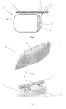
- Figure 5 shows a lens 16 according to an embodiment of the invention.
- the lens 16 comprises at least one break line 26.
- the lens 16 is mounted on a headlamp housing so that at least one protrusion will be located in the vicinity of the at least one break line 26 to initiate breakage of the lens 16 along the break line 26.
- a break line 26 may of course extend from one side of the lens 16 to the other.
- the lens 16 also includes a flange 28, such as a glue flange, which comprises at least one groove 30 that is arranged to receive the at least one protrusion if/when the headlamp assembly is subjected to an impact or compression force in the event of a collision.
- a flange 28 such as a glue flange, which comprises at least one groove 30 that is arranged to receive the at least one protrusion if/when the headlamp assembly is subjected to an impact or compression force in the event of a collision.
- Figure 6 shows a plurality of protrusions 18, on a headlamp housing 14 for example, and a plurality of grooves 30, on the glue flange 28 of a lens 16 for example.
- the at least one groove 30 and the at least one protrusion 18 have a maximum extension in the direction in which the protrusion 18 is arranged to be pushed in the event of a collision, and the maximum extension G of the at least one groove 30 is smaller than the maximum extension P of the at least one protrusion 18 to initiate breakage of the lens 16 when the at least one protrusion 18 is pushed into the at least one groove 30.
- the maximum extension of the at least one groove 30 may for example be up to 3 mm, up to 5 mm or up to 10 mm or more.
- a protrusion 28 may be arranged to move through a distance D before it makes contact with a corresponding groove 30.
- the distance D may be arranged to be 1 to 2mm, or up to 5 mm.
- the at least one protrusion 18 could be provided on a lens 16 and the at least one groove 30 could be provided on the housing 14, or a combination of protrusions 18 and grooves 30 could be provided on both the housing 14 and the lens. All of the protrusions 18 and grooves 30 of a headlamp assembly 12 do not necessarily have to be of the same shape, size and dimensions.
Landscapes
- Engineering & Computer Science (AREA)
- Mechanical Engineering (AREA)
- Chemical & Material Sciences (AREA)
- Combustion & Propulsion (AREA)
- Transportation (AREA)
- Lighting Device Outwards From Vehicle And Optical Signal (AREA)
- Non-Portable Lighting Devices Or Systems Thereof (AREA)
Abstract
Description
- The present invention concerns a headlamp assembly for a vehicle and a vehicle comprising such a headlamp assembly.
- A headlamp is a lamp that is usually attached to the front of a vehicle, such a car, with the purpose of illuminating the road ahead during periods of low visibility, such as during the night or in bad weather conditions and/or to increase the conspicuity of vehicles in motion during the daytime. Headlamps usually comprise a light source, a reflector and a cover with a front surface forming a lens and are positioned in pairs, one or more on each side of the front of a vehicle.
- Some headlamps are designed so that the risk of injuries to a pedestrian is reduced in the event of a collision with a pedestrian.
- For example, the abstract of German patent application no.
DE 102006007449 describes a headlamp that is attached to a carrying element, whereby the headlamp and the carrying element are separated by a gap in order to facilitate the adjustment of the position of the headlamp. In case of a collision with a pedestrian, the headlamp unit is pushed into the gap towards the carrying element. Small segments protruding at a right angle from the surface of the carrying element create indents in the rear of the headlamp housing resulting in a reduction of the forces of the impact. - European patent no.
EP 1 120 309 concerns a headlamp housing that has a front light output opening covered by a lamp glass. The headlamp housing has a side section that extends inwards from the light output opening and has at least one rupture point, i.e. a mechanically weakened deformable portion, designed for absorbing the force upon impact with a pedestrian. Parts of the headlamp housing on either side of the rupture point are arranged to be telescopically inter-fitting. Since such an arrangement leads to a local deformation only in the area of rupture point(s), the energy absorption of the headlamp is limited by the maximum possible deformation in the area of the rupture point(s). - An object of the present invention is to provide an improved headlamp assembly comprising a housing and a lens for a vehicle, and more particularly to provide a pedestrian-friendly headlamp assembly whereby the risk of injuries to a pedestrian is reduced in the event of a collision with a pedestrian.
- The expression "pedestrian" as used in this document is intended to mean a human being or other living creature, and includes human beings using a vehicle, such as a bicycle or a motorbike, and is not therefore restricted to human beings moving on foot.
- This object is achieved by headlamp assembly that comprises at least one protrusion that is arranged to be pushed into the lens, or whereby the lens is arranged to be pushed against the at least one protrusion, to initiate controlled deformation and/or breakage of the lens if/when the headlamp assembly is subjected to an impact or compression force in the event of a collision. A stress concentration will occur at the point at which the at least one protrusion contacts the lens, which will result in the deformation/breakage of the lens if the impact force exceeds a predetermined magnitude.
- The headlamp assembly therefore comprises at least one passive trigger to initiate controlled deformation and/or breakage of the lens since the present invention is based on the insight that a headlamp lens contributes to pedestrian injury during impacts and that the energy-absorbing capacity of a headlamp assembly can be increased by triggering the deformation/breakage of its lens. By providing a headlamp assembly with a readily deformable/breakable lens, the force exerted by the lens on a pedestrian in the event of a collision will be reduced, which may reduce the number of injuries suffered by a pedestrian or the severity of the injuries. Furthermore, the deformation/breakage of the lens will result in a smoother impact because of a low force level during initial impact and high energy absorption due to the high deformation/breakage of the lens.
- Additionally, the headlamp assembly gives a designer maximum freedom to achieve an optimum design with regard to pedestrian protection with a very minor need for additional components and manufacturing efforts.
- A further advantage is that since the lens is arranged to be deformed/broken rather than to be kept intact and displaced rearwards with or without the whole headlamp assembly, no substantial additional space behind the lens or headlamp assembly is necessarily required. The at least one protrusion and the lens may for example be arranged to be placed in contact with each other during the manufacture, installation or use of the headlamp assembly, or the at least one protrusion may be arranged to be placed within a distance of up to 5 mm for example from a surface of the lens, whereby the lens and/or protrusion are arranged to be displaced through small distance in the event of a collision with a pedestrian.
- The expression "lens" as used in this document is intended to mean a piece of transparent or semi-transparent material, which is optionally used to focus rays of light, i.e. the lens may merely be a cover for a lamp or light source. The lens may be curved or substantially flat and be of any shape or form. A headlamp may be arranged to comprise a plurality of such lenses. Alternatively a headlamp assembly may comprise a plurality of lamps or light sources and a single lens.
- As regards the expression "deformation/breakage"; whether a lens deforms and/or breaks will depend on the physical properties of the material from which the lens is made and the magnitude of the impact/compression forces to which it is subjected in the event of a collision. The lens material and the design and location of the protrusions may be selected so as to achieve the desired deformation/breakage for a particular impact or compression force.
- The expression "controlled" deformation/breakage is intended to mean that the headlamp assembly comprises at least one designated protrusion that is specifically provided to initiate the deformation/breakage of the lens.
- It should be noted that the at least one "protrusion" may be arranged to "protrude" only in the event of a collision. For example, at least one protrusion may be arranged inside a plastically deformable material located between a headlamp housing and a lens for example, whereby the softer plastically deformable material is arranged to be displaced to reveal the at least one protrusion in the event of a collision.
- According to an embodiment of the invention the at least one protrusion is provided on the housing. It should be noted that part of a vehicle comprising a headlamp assembly according to the present invention may constitute at least part of the headlamp assembly housing.
- According to another embodiment of the invention the lens comprises at least one break line, i.e. at least one weakened area, such as an area of reduced thickness, in order to promote breakage of the lens in the at least one weakened area, whereby the at least one protrusion is arranged in the vicinity of the at least one break line.
- According to a further embodiment of the invention the lens comprises at least one groove that is arranged to receive the at least one protrusion if/when the headlamp assembly is subjected to an impact or compression force in the event of a collision
- According to an embodiment of the invention the at least one groove and the at least one protrusion have a maximum extension, and the maximum extension of the at least one groove is smaller than the maximum extension of the at least one protrusion.
- According to another embodiment of the invention the lens comprises a flange, such as a glue flange, and the at least one groove is provided on the flange.
- According to a further embodiment of the invention the lens comprises at least one continuous or non-continuous, uniform or non-uniform film, layer or coating that is arranged to prevent parts of a broken lens from being scattered if/when the headlamp assembly or the lens is subjected to an impact or compression force in the event of a collision resulting in breakage of the lens. The risk that a relatively sharp edge of the broken lens may injure the pedestrian, a person at the scene of the collision or a person repairing or replacing the headlamp assembly is thereby reduced.
- According to an embodiment of the invention the lens comprises plastic or is made entirely of plastic.
- The present invention also concerns a lens that is suitable for use in a headlamp assembly according to the present invention.
- The present invention also concerns a vehicle that comprises a headlamp assembly or a lens according to any of the embodiments of the invention. The present invention is particularly, but not exclusively intended for use in passenger cars, trucks, buses, heavy goods vehicles or any other road-using vehicle or moving object.
- The present invention further concerns a vehicle comprising a headlamp assembly that comprises a housing and a lens, whereby the vehicle comprises a vehicle component, other than a headlamp, that comprises at least one protrusion that is arranged to be pushed into the lens, or whereby the lens is arranged to be pushed against the at least one protrusion, to initiate controlled deformation and/or breakage of the lens if/when the vehicle component is subjected to an impact or compression force in the event of a collision.
- According to an embodiment of the invention the at least one protrusion is provided on a vehicle component that is located in the vicinity of the lens, such as a bonnet or a fender.
- According to another embodiment of the invention the lens is arranged to comprise at least one groove that is arranged to receive the at least one protrusion if/when the headlamp assembly or the lens is subjected to an impact or compression force in the event of a collision. Further embodiments of the vehicle are disclosed in the appended claims.
- The present invention will hereinafter be further explained by means of non-limiting examples with reference to the appended figures where;
- Figure 1
- shows a vehicle according to an embodiment of the invention,
- Figures 2 & 3
- show headlamp assemblies according to embodiments of the invention,
- Figure 4
- shows a vehicle component of a vehicle according to an embodiment of the invention,
- Figure 5
- shows a lens according to an embodiment of the invention, and
- Figure 6
- shows part of a headlamp assembly according to an embodiment of the invention
- It should be noted that the drawings have not necessarily been drawn to scale and that the dimensions of certain features may have been exaggerated for the sake of clarity.
-
Figure 1 shows avehicle 10 comprising aheadlamp assembly 12. Theheadlamp assembly 12 may comprise any type of lamp, such as a reflector lamp in which a light source is placed at, or near the focus of a reflector, or a projector lamp in which a light source is located at one focus of an ellipsoidal reflector and has a condenser lens at the front of the lamp. A light source may for example be a tungsten filament bulb, a halogen filament bulb, a gas discharge lamp or a light emitting diode. -
Figure 2 shows aheadlamp assembly 12 according to an embodiment of the invention, which comprises ahousing 14 and alens 16 comprising clear plastic or glass for example. Thehousing 14 comprises a plurality ofprotrusions lens 16. Thelens 16 is arranged to be pushed against theprotrusions headlamp assembly 12 is subjected to an impact or compression force that acts in the direction of any of the block arrows shown infigure 2 in the event of a collision. In the illustrated embodiment theprotrusions housing 14 and may either be integrally formed with thehousing 14, which may reduce manufacturing and assembly complexity and costs, or mounted directly or indirectly thereon. - Preferably the
housing 14 and thelens 16 are separate parts, whereby thelens 16 is attached to the housing by any conventional means, such as via adhesion, in which case a broken ordeformed lens 16 may easily be replaced without having to replace the whole headlamp assembly, which reduces repair costs and complexity. Thehousing 14 may for example be, at least in part, constituted by a cavity in the chassis of a vehicle. Alternatively, thehousing 14 and thelens 16 may be made out of the same material and may optionally be formed as an integrated unit. In the latter case thelens 16 is the part of theheadlamp 12 that a pedestrian may make contact with in the event of a collision. The headlamp assembly according to the invention is namely arranged so that it is the part of a lens with which a pedestrian may make contact in the event of a collision that is arranged to break or deform. -
Figure 3 shows aheadlamp assembly 12 according to another embodiment of the invention. In the illustrated embodiment theheadlamp assembly 12 comprises afirst protrusion 18a provided directly on itshousing 14 at a location in front of thelens 16, whereby part of thehousing 14 extends past the front of thelens 16, and asecond protrusion 18b provided on a component, such as aflange 20, which is mounted behind thelens 16 on a component located outside thehousing 14. Theprotrusion 18a is arranged to be pushed against the front of thelens 16 if/when thehousing 14 is subjected to an impact or compression force in the direction of the two block arrows at the top offigure 3 in the event of a collision. - The back surface of the
lens 16 is arranged to be pushed againstprotrusion 18b if/when thelens 16 is subjected to an impact or compression force in the direction of the block arrow at the bottom offigure 3 in the event of a collision. It should be noted thatprotrusions 18 may be arranged to be pushed against any part of alens 16 including its upper and lower side surfaces and any part of alens 16 may be arranged to be pushed against aprotrusion 18 located anywhere in the vicinity of thelens 16. - It should be noted that the deformation/breakage of a lens may be arranged to subsequently initiate the deformation/breakage of the housing of a headlamp assembly or vice versa, the deformation/breakage of the housing of a headlamp assembly may be arranged to subsequently initiate the deformation/breakage of the lens. Furthermore, the lens and housing of a headlamp assembly according to the present invention may deform/break at substantially the same time.
-
Figure 4 shows aheadlamp assembly 12 in which thelens 16 comprises at least one continuous, non-uniform film, layer orcoating 22 on at least part of its front surface, which is arranged to prevent parts of a broken lens from being scattered if/when the headlamp assembly or the lens is subjected to an impact or compression force in the event of a collision. The film, layer orcoating 22 may additionally or alternatively be provided on at least part of the back surface of thelens 22 or inside the material constituting thelens 16, i.e. between its front and back surfaces of thelens 16. It should be noted that the at least one film, layer orcoating 22 may be arranged to extend beyond the outer boundaries of thelens 16 and be attached to thehousing 14 or some other component in the vicinity of thelens 16. -
Figure 4 also shows avehicle component 24, such as a bonnet or a fender, that is located in the vicinity of thelens 16, and that comprises aprotrusion 18 that is arranged to be pushed against the front surface of thelens 16 if/when thevehicle component 24 is subjected to an impact or compression force in the direction of the block arrows shown infigure 4 in the event of a collision, when a pedestrian is thrown onto the bonnet of a vehicle for example. -
Figure 5 shows alens 16 according to an embodiment of the invention. Thelens 16 comprises at least onebreak line 26. Thelens 16 is mounted on a headlamp housing so that at least one protrusion will be located in the vicinity of the at least onebreak line 26 to initiate breakage of thelens 16 along thebreak line 26. Abreak line 26 may of course extend from one side of thelens 16 to the other. - The
lens 16 also includes aflange 28, such as a glue flange, which comprises at least onegroove 30 that is arranged to receive the at least one protrusion if/when the headlamp assembly is subjected to an impact or compression force in the event of a collision. -
Figure 6 shows a plurality ofprotrusions 18, on aheadlamp housing 14 for example, and a plurality ofgrooves 30, on theglue flange 28 of alens 16 for example. According to an embodiment of the invention the at least onegroove 30 and the at least oneprotrusion 18 have a maximum extension in the direction in which theprotrusion 18 is arranged to be pushed in the event of a collision, and the maximum extension G of the at least onegroove 30 is smaller than the maximum extension P of the at least oneprotrusion 18 to initiate breakage of thelens 16 when the at least oneprotrusion 18 is pushed into the at least onegroove 30. The maximum extension of the at least onegroove 30 may for example be up to 3 mm, up to 5 mm or up to 10 mm or more. It should be noted that aprotrusion 28 may be arranged to move through a distance D before it makes contact with a correspondinggroove 30. The distance D may be arranged to be 1 to 2mm, or up to 5 mm. - It should be noted that the at least one
protrusion 18 could be provided on alens 16 and the at least onegroove 30 could be provided on thehousing 14, or a combination ofprotrusions 18 andgrooves 30 could be provided on both thehousing 14 and the lens. All of theprotrusions 18 andgrooves 30 of aheadlamp assembly 12 do not necessarily have to be of the same shape, size and dimensions. - It should be noted that any of the features shown in any of the figures may be combined in any way with any number of the features shown in any of the other figures.
- Further modifications of the invention within the scope of the claims would be apparent to a skilled person. For example, even though the claims are directed to a headlamp assembly and a vehicle, the present invention could be applied to any component of a non-stationary object that may collide with a human being, or any other living creature, when the object is in use.
Claims (12)
- Headlamp assembly (12) for a vehicle (10), comprising a housing (14) and a lens (16), characterized in that said headlamp assembly (12) comprises at least one protrusion (18) that is arranged be pushed into said lens (16), or whereby said lens (16) is arranged to be pushed against said at least one protrusion (18), to initiate controlled deformation and/or breakage of said lens (16) if/when said headlamp assembly (12) is subjected to an impact or compression force in the event of a collision.
- Headlamp assembly (12) according to claim 1, characterized in that said at least one protrusion (18) is provided on said housing (14).
- Headlamp assembly (12) according to claim 1 or 2, characterized in that said lens (16) comprises at least one break line (26), and that said at least one protrusion (18) is arranged in the vicinity of said at least one break line (26).
- Headlamp assembly (12) according to any of the preceding claims, characterized in that said lens (16) comprises at least one groove (30) that is arranged to receive said at least one protrusion (18) if/when said headlamp assembly (12) is subjected to an impact or compression force in the event of a collision
- Headlamp assembly (12) according to claim 4, characterized in that said at least one groove (30) and said at least one protrusion (18) have a maximum extension, and the maximum extension of said at least one groove (30) is smaller than the maximum extension of said at least one protrusion (18).
- Headlamp assembly (12) according to claims 4 or 5, characterized in that said lens (16) comprises a flange (28), such as a glue flange, and said at least one groove (30) is provided on said flange (28).
- Headlamp assembly (12) according to any of the preceding claims, characterized in that said lens (16) comprises at least one film, layer or coating (22) that is arranged to prevent parts of a broken lens (16) from being scattered if/when said headlamp assembly (12) or said lens (16) is subjected to an impact or compression force in the event of a collision.
- Headlamp assembly (12) according to any of the preceding claims, characterized in that said lens (16) comprises plastic.
- Vehicle (10), characterized in that it comprises a headlamp assembly (12) according to any of claims 1-8.
- Vehicle (10) comprising a headlamp assembly (12) that comprises a housing (14) and a lens (16), characterized in that said vehicle (10) comprises at least one vehicle component (24), other than a headlamp, which comprises at least one protrusion (18) that is arranged to be pushed into said lens (16), or whereby said lens (16) is arranged to be pushed against said at least one protrusion (18), to initiate controlled deformation and/or breakage of said lens (16) if/when said vehicle component (24) or said lens (16) is subjected to an impact or compression force in the event of a collision.
- Vehicle (10) according to claim 10, characterized in that said at least one protrusion (18) is provided on a vehicle component (24) that is located in the vicinity of said lens (16).
- Vehicle (10) according to claim 11, characterized in that said vehicle component (24) is a bonnet or a fender.
Priority Applications (4)
| Application Number | Priority Date | Filing Date | Title |
|---|---|---|---|
| DE602008005409T DE602008005409D1 (en) | 2008-04-24 | 2008-04-24 | Headlight assembly and vehicle |
| EP08155097A EP2112020B1 (en) | 2008-04-24 | 2008-04-24 | Headlamp assembly and vehicle |
| CN2009100053741A CN101566298B (en) | 2008-04-24 | 2009-02-20 | Headlamp assembly and vehicle |
| US12/429,265 US8152345B2 (en) | 2008-04-24 | 2009-04-24 | Pedestrian safety headlamp assembly |
Applications Claiming Priority (1)
| Application Number | Priority Date | Filing Date | Title |
|---|---|---|---|
| EP08155097A EP2112020B1 (en) | 2008-04-24 | 2008-04-24 | Headlamp assembly and vehicle |
Publications (2)
| Publication Number | Publication Date |
|---|---|
| EP2112020A1 true EP2112020A1 (en) | 2009-10-28 |
| EP2112020B1 EP2112020B1 (en) | 2011-03-09 |
Family
ID=39639630
Family Applications (1)
| Application Number | Title | Priority Date | Filing Date |
|---|---|---|---|
| EP08155097A Ceased EP2112020B1 (en) | 2008-04-24 | 2008-04-24 | Headlamp assembly and vehicle |
Country Status (4)
| Country | Link |
|---|---|
| US (1) | US8152345B2 (en) |
| EP (1) | EP2112020B1 (en) |
| CN (1) | CN101566298B (en) |
| DE (1) | DE602008005409D1 (en) |
Cited By (1)
| Publication number | Priority date | Publication date | Assignee | Title |
|---|---|---|---|---|
| WO2015001256A1 (en) * | 2013-07-03 | 2015-01-08 | Peugeot Citroën Automobiles SA | Motor vehicle headlight |
Families Citing this family (9)
| Publication number | Priority date | Publication date | Assignee | Title |
|---|---|---|---|---|
| FR2983141B1 (en) * | 2011-11-24 | 2014-08-08 | Renault Sa | A PROJECTOR ASSEMBLY AND ITS MOUNTING DEVICE LIMITING THE REPAIRS OF THE ADJACENT WING DURING A SHOCK AND THE CORRESPONDING VEHICLE |
| DE102013200975A1 (en) * | 2013-01-22 | 2014-07-24 | Ford Global Technologies, Llc | headlights |
| EP2985210B1 (en) | 2013-04-08 | 2020-03-18 | Toyota Jidosha Kabushiki Kaisha | Structure for front part of vehicle |
| CN104654162B (en) * | 2013-11-21 | 2017-06-20 | 丹阳市飞越车辆附件有限公司 | Travelling car light |
| US9221387B1 (en) * | 2014-07-23 | 2015-12-29 | GM Global Technology Operations LLC | Breakaway headlamp mounting system |
| US10302267B2 (en) * | 2014-10-27 | 2019-05-28 | Ford Global Technologies, Llc | Color infused automobile headlamp lens |
| US10288246B1 (en) * | 2018-01-10 | 2019-05-14 | Ford Global Technologies, Llc | Vehicle headlamp assembly |
| US20230147937A1 (en) * | 2021-11-11 | 2023-05-11 | GM Global Technology Operations LLC | Impact ring |
| US12128833B2 (en) * | 2022-08-26 | 2024-10-29 | Ford Global Technologies, Llc | Light assembly for motor vehicle |
Citations (9)
| Publication number | Priority date | Publication date | Assignee | Title |
|---|---|---|---|---|
| EP1120309A2 (en) | 2000-01-28 | 2001-08-01 | Volkswagen Aktiengesellschaft | Headlight housing |
| EP1400404A1 (en) * | 2002-09-20 | 2004-03-24 | Valeo Vision | Vehicle headlamp with improved shock absorbing means |
| DE10334033A1 (en) * | 2003-07-18 | 2005-02-17 | Automotive Lighting Reutlingen Gmbh | Front hood arrangement for automobile with deformation of front hood upon impact loading for protection of pedestrian thrown onto hood |
| JP2005280415A (en) * | 2004-03-29 | 2005-10-13 | Nissan Motor Co Ltd | Mounting structure for vehicle headlamps |
| EP1736358A1 (en) * | 2005-06-21 | 2006-12-27 | Peugeot Citroen Automobiles SA | Headlamp for a vehicle |
| JP2007045351A (en) * | 2005-08-11 | 2007-02-22 | Nissan Motor Co Ltd | Shock absorption structure of headlamp |
| DE102006007449A1 (en) | 2006-02-17 | 2007-08-23 | Automotive Lighting Reutlingen Gmbh | Vehicle, comprises headlights resting on breaking elements acting on housing for protection of pedestrian in case of collision |
| EP1886870A1 (en) * | 2006-07-31 | 2008-02-13 | Valeo Vision | Headlight for automobile |
| DE102006047420A1 (en) * | 2006-10-06 | 2008-04-10 | Daimler Ag | Illuminant unit arrangement for front end area of passenger car, has deformation unit of housing comprising impact area, and preset breaking area controllably destroyed when breaking area impinges at impact area during accident |
Family Cites Families (10)
| Publication number | Priority date | Publication date | Assignee | Title |
|---|---|---|---|---|
| US4894761A (en) * | 1987-08-10 | 1990-01-16 | Signam Limited | Protective shield for a vehicle lamp assembly |
| JPH0740441B2 (en) * | 1990-08-17 | 1995-05-01 | 株式会社小糸製作所 | Automotive headlight device |
| US6331068B1 (en) * | 1999-02-18 | 2001-12-18 | Lacks Industries, Inc. | Flexible lamp mounting |
| JP3967032B2 (en) * | 1999-03-10 | 2007-08-29 | 株式会社小糸製作所 | Manufacturing method of vehicular lamp |
| JP4345041B2 (en) * | 2000-02-07 | 2009-10-14 | マツダ株式会社 | Vehicle lighting |
| US7040793B2 (en) * | 2002-11-05 | 2006-05-09 | Lacks Enterprises, Inc. | Controlled deformable headlamp assembly |
| TW592324U (en) * | 2002-12-19 | 2004-06-11 | Coretronic Corp | Back light apparatus |
| JP2006019053A (en) * | 2004-06-30 | 2006-01-19 | Toshiba Lighting & Technology Corp | Metal halide lamps and headlamps |
| FR2876068B1 (en) * | 2004-10-05 | 2006-12-15 | Valeo Vision Sa | ENERGY DAMPING PROJECTOR FOR MOTOR VEHICLE AND METHOD FOR ABSORBING ENERGY FROM PIECE SHOCK |
| FR2918950B1 (en) * | 2007-07-16 | 2009-10-16 | Peugeot Citroen Automobiles Sa | FRONT PANEL OF MOTOR VEHICLE COMPRISING AT LEAST ONE OPTICAL BLOCK ICE AND A BUMPER |
-
2008
- 2008-04-24 EP EP08155097A patent/EP2112020B1/en not_active Ceased
- 2008-04-24 DE DE602008005409T patent/DE602008005409D1/en active Active
-
2009
- 2009-02-20 CN CN2009100053741A patent/CN101566298B/en not_active Expired - Fee Related
- 2009-04-24 US US12/429,265 patent/US8152345B2/en active Active
Patent Citations (9)
| Publication number | Priority date | Publication date | Assignee | Title |
|---|---|---|---|---|
| EP1120309A2 (en) | 2000-01-28 | 2001-08-01 | Volkswagen Aktiengesellschaft | Headlight housing |
| EP1400404A1 (en) * | 2002-09-20 | 2004-03-24 | Valeo Vision | Vehicle headlamp with improved shock absorbing means |
| DE10334033A1 (en) * | 2003-07-18 | 2005-02-17 | Automotive Lighting Reutlingen Gmbh | Front hood arrangement for automobile with deformation of front hood upon impact loading for protection of pedestrian thrown onto hood |
| JP2005280415A (en) * | 2004-03-29 | 2005-10-13 | Nissan Motor Co Ltd | Mounting structure for vehicle headlamps |
| EP1736358A1 (en) * | 2005-06-21 | 2006-12-27 | Peugeot Citroen Automobiles SA | Headlamp for a vehicle |
| JP2007045351A (en) * | 2005-08-11 | 2007-02-22 | Nissan Motor Co Ltd | Shock absorption structure of headlamp |
| DE102006007449A1 (en) | 2006-02-17 | 2007-08-23 | Automotive Lighting Reutlingen Gmbh | Vehicle, comprises headlights resting on breaking elements acting on housing for protection of pedestrian in case of collision |
| EP1886870A1 (en) * | 2006-07-31 | 2008-02-13 | Valeo Vision | Headlight for automobile |
| DE102006047420A1 (en) * | 2006-10-06 | 2008-04-10 | Daimler Ag | Illuminant unit arrangement for front end area of passenger car, has deformation unit of housing comprising impact area, and preset breaking area controllably destroyed when breaking area impinges at impact area during accident |
Cited By (4)
| Publication number | Priority date | Publication date | Assignee | Title |
|---|---|---|---|---|
| WO2015001256A1 (en) * | 2013-07-03 | 2015-01-08 | Peugeot Citroën Automobiles SA | Motor vehicle headlight |
| FR3008046A1 (en) * | 2013-07-03 | 2015-01-09 | Peugeot Citroen Automobiles Sa | MOTOR VEHICLE PROJECTOR |
| CN105358373A (en) * | 2013-07-03 | 2016-02-24 | 标致·雪铁龙汽车公司 | Motor vehicle headlight |
| CN105358373B (en) * | 2013-07-03 | 2018-08-21 | 标致·雪铁龙汽车公司 | The headlamp of motor vehicles |
Also Published As
| Publication number | Publication date |
|---|---|
| US8152345B2 (en) | 2012-04-10 |
| US20090268482A1 (en) | 2009-10-29 |
| CN101566298A (en) | 2009-10-28 |
| CN101566298B (en) | 2012-07-18 |
| EP2112020B1 (en) | 2011-03-09 |
| DE602008005409D1 (en) | 2011-04-21 |
Similar Documents
| Publication | Publication Date | Title |
|---|---|---|
| EP2112020B1 (en) | Headlamp assembly and vehicle | |
| EP2511134A1 (en) | Vehicle Light Unit | |
| EP1332915A2 (en) | A pedestrian protection headlamp assembly | |
| CN102414047B (en) | Device for viewing front-lateral area of vehicle | |
| JP3762904B2 (en) | Boundary structure between bonnet and headlight | |
| US9440578B2 (en) | Assembly of a headlight and a device for mounting same, which reduces the amount of repairs to the adjacent fender upon an impact, and related vehicle | |
| US7967488B2 (en) | Breakable structure of headlamp for vehicles | |
| US8092056B2 (en) | Light module and lighting device | |
| US9302610B2 (en) | Motor vehicle headlight with energy absorbing feature | |
| JP2006001344A (en) | Mounting structure for vehicle lamp | |
| RU2565439C1 (en) | Headlight device for vehicle | |
| KR101518216B1 (en) | Side marker lamp for vehicle | |
| JP5848972B2 (en) | Headlamp mounting structure | |
| CN214745458U (en) | Lamp for a motor vehicle and motor vehicle comprising a lamp for a motor vehicle | |
| KR101033328B1 (en) | Automotive Headlamp Assembly | |
| CN116997484A (en) | Lighting devices for motor vehicles | |
| JP4504136B2 (en) | Vehicular lamp with impact mitigation configuration | |
| KR101063223B1 (en) | Pedestrian protection headlamp structure | |
| KR100534862B1 (en) | Connection structure of head ramp | |
| JP2007015453A (en) | Vehicle lamp and mounting structure of vehicle lamp | |
| US7122136B2 (en) | Glare prevention feature | |
| JP2019023004A (en) | Lamp lighting confirmation structure | |
| JP2007537923A (en) | Improved automotive headlamp | |
| CN204149933U (en) | Fog light set for vehicle | |
| GB2395000A (en) | A headlamp assembly for a motor vehicle |
Legal Events
| Date | Code | Title | Description |
|---|---|---|---|
| PUAI | Public reference made under article 153(3) epc to a published international application that has entered the european phase |
Free format text: ORIGINAL CODE: 0009012 |
|
| AK | Designated contracting states |
Kind code of ref document: A1 Designated state(s): AT BE BG CH CY CZ DE DK EE ES FI FR GB GR HR HU IE IS IT LI LT LU LV MC MT NL NO PL PT RO SE SI SK TR |
|
| AX | Request for extension of the european patent |
Extension state: AL BA MK RS |
|
| 17P | Request for examination filed |
Effective date: 20100203 |
|
| 17Q | First examination report despatched |
Effective date: 20100224 |
|
| AKX | Designation fees paid |
Designated state(s): DE GB SE |
|
| GRAP | Despatch of communication of intention to grant a patent |
Free format text: ORIGINAL CODE: EPIDOSNIGR1 |
|
| GRAS | Grant fee paid |
Free format text: ORIGINAL CODE: EPIDOSNIGR3 |
|
| GRAA | (expected) grant |
Free format text: ORIGINAL CODE: 0009210 |
|
| AK | Designated contracting states |
Kind code of ref document: B1 Designated state(s): DE GB SE |
|
| REG | Reference to a national code |
Ref country code: GB Ref legal event code: FG4D |
|
| REF | Corresponds to: |
Ref document number: 602008005409 Country of ref document: DE Date of ref document: 20110421 Kind code of ref document: P |
|
| REG | Reference to a national code |
Ref country code: DE Ref legal event code: R096 Ref document number: 602008005409 Country of ref document: DE Effective date: 20110421 |
|
| REG | Reference to a national code |
Ref country code: SE Ref legal event code: TRGR |
|
| RAP2 | Party data changed (patent owner data changed or rights of a patent transferred) |
Owner name: VOLVO CAR CORPORATION |
|
| PLBE | No opposition filed within time limit |
Free format text: ORIGINAL CODE: 0009261 |
|
| STAA | Information on the status of an ep patent application or granted ep patent |
Free format text: STATUS: NO OPPOSITION FILED WITHIN TIME LIMIT |
|
| 26N | No opposition filed |
Effective date: 20111212 |
|
| REG | Reference to a national code |
Ref country code: DE Ref legal event code: R097 Ref document number: 602008005409 Country of ref document: DE Effective date: 20111212 |
|
| REG | Reference to a national code |
Ref country code: DE Ref legal event code: R081 Ref document number: 602008005409 Country of ref document: DE Owner name: VOLVO CAR CORPORATION, SE Free format text: FORMER OWNER: FORD GLOBAL TECHNOLOGIES, LLC, DEARBORN, US Effective date: 20120419 Ref country code: DE Ref legal event code: R082 Ref document number: 602008005409 Country of ref document: DE Representative=s name: LOUIS, POEHLAU, LOHRENTZ, DE Effective date: 20120419 Ref country code: DE Ref legal event code: R081 Ref document number: 602008005409 Country of ref document: DE Owner name: VOLVO CAR CORPORATION, SE Free format text: FORMER OWNER: FORD GLOBAL TECHNOLOGIES, LLC, DEARBORN, MICH., US Effective date: 20120419 |
|
| REG | Reference to a national code |
Ref country code: GB Ref legal event code: 732E Free format text: REGISTERED BETWEEN 20120621 AND 20120627 |
|
| PGFP | Annual fee paid to national office [announced via postgrant information from national office to epo] |
Ref country code: SE Payment date: 20190416 Year of fee payment: 12 |
|
| PGFP | Annual fee paid to national office [announced via postgrant information from national office to epo] |
Ref country code: GB Payment date: 20190408 Year of fee payment: 12 |
|
| PG25 | Lapsed in a contracting state [announced via postgrant information from national office to epo] |
Ref country code: SE Free format text: LAPSE BECAUSE OF NON-PAYMENT OF DUE FEES Effective date: 20200425 |
|
| GBPC | Gb: european patent ceased through non-payment of renewal fee |
Effective date: 20200424 |
|
| PG25 | Lapsed in a contracting state [announced via postgrant information from national office to epo] |
Ref country code: GB Free format text: LAPSE BECAUSE OF NON-PAYMENT OF DUE FEES Effective date: 20200424 |
|
| P01 | Opt-out of the competence of the unified patent court (upc) registered |
Effective date: 20231212 |
|
| PGFP | Annual fee paid to national office [announced via postgrant information from national office to epo] |
Ref country code: DE Payment date: 20240320 Year of fee payment: 17 |
|
| REG | Reference to a national code |
Ref country code: DE Ref legal event code: R119 Ref document number: 602008005409 Country of ref document: DE |
|
| PG25 | Lapsed in a contracting state [announced via postgrant information from national office to epo] |
Ref country code: DE Free format text: LAPSE BECAUSE OF NON-PAYMENT OF DUE FEES Effective date: 20251104 |