EP2111917B1 - Statischer Mischer, Verfahren zur Herstellung eines solchen und Mischanordnung - Google Patents
Statischer Mischer, Verfahren zur Herstellung eines solchen und Mischanordnung Download PDFInfo
- Publication number
- EP2111917B1 EP2111917B1 EP09005543A EP09005543A EP2111917B1 EP 2111917 B1 EP2111917 B1 EP 2111917B1 EP 09005543 A EP09005543 A EP 09005543A EP 09005543 A EP09005543 A EP 09005543A EP 2111917 B1 EP2111917 B1 EP 2111917B1
- Authority
- EP
- European Patent Office
- Prior art keywords
- mixer
- guide elements
- webs
- flow direction
- flow
- Prior art date
- Legal status (The legal status is an assumption and is not a legal conclusion. Google has not performed a legal analysis and makes no representation as to the accuracy of the status listed.)
- Not-in-force
Links
Images


Classifications
-
- B—PERFORMING OPERATIONS; TRANSPORTING
- B01—PHYSICAL OR CHEMICAL PROCESSES OR APPARATUS IN GENERAL
- B01F—MIXING, e.g. DISSOLVING, EMULSIFYING OR DISPERSING
- B01F25/00—Flow mixers; Mixers for falling materials, e.g. solid particles
- B01F25/40—Static mixers
- B01F25/42—Static mixers in which the mixing is affected by moving the components jointly in changing directions, e.g. in tubes provided with baffles or obstructions
- B01F25/43—Mixing tubes, e.g. wherein the material is moved in a radial or partly reversed direction
- B01F25/431—Straight mixing tubes with baffles or obstructions that do not cause substantial pressure drop; Baffles therefor
- B01F25/4315—Straight mixing tubes with baffles or obstructions that do not cause substantial pressure drop; Baffles therefor the baffles being deformed flat pieces of material
- B01F25/43151—Straight mixing tubes with baffles or obstructions that do not cause substantial pressure drop; Baffles therefor the baffles being deformed flat pieces of material composed of consecutive sections of deformed flat pieces of material
-
- B—PERFORMING OPERATIONS; TRANSPORTING
- B21—MECHANICAL METAL-WORKING WITHOUT ESSENTIALLY REMOVING MATERIAL; PUNCHING METAL
- B21D—WORKING OR PROCESSING OF SHEET METAL OR METAL TUBES, RODS OR PROFILES WITHOUT ESSENTIALLY REMOVING MATERIAL; PUNCHING METAL
- B21D53/00—Making other particular articles
-
- B—PERFORMING OPERATIONS; TRANSPORTING
- B01—PHYSICAL OR CHEMICAL PROCESSES OR APPARATUS IN GENERAL
- B01F—MIXING, e.g. DISSOLVING, EMULSIFYING OR DISPERSING
- B01F23/00—Mixing according to the phases to be mixed, e.g. dispersing or emulsifying
- B01F23/20—Mixing gases with liquids
- B01F23/21—Mixing gases with liquids by introducing liquids into gaseous media
- B01F23/213—Mixing gases with liquids by introducing liquids into gaseous media by spraying or atomising of the liquids
-
- B—PERFORMING OPERATIONS; TRANSPORTING
- B01—PHYSICAL OR CHEMICAL PROCESSES OR APPARATUS IN GENERAL
- B01F—MIXING, e.g. DISSOLVING, EMULSIFYING OR DISPERSING
- B01F25/00—Flow mixers; Mixers for falling materials, e.g. solid particles
- B01F25/40—Static mixers
- B01F25/42—Static mixers in which the mixing is affected by moving the components jointly in changing directions, e.g. in tubes provided with baffles or obstructions
- B01F25/43—Mixing tubes, e.g. wherein the material is moved in a radial or partly reversed direction
- B01F25/431—Straight mixing tubes with baffles or obstructions that do not cause substantial pressure drop; Baffles therefor
- B01F25/4315—Straight mixing tubes with baffles or obstructions that do not cause substantial pressure drop; Baffles therefor the baffles being deformed flat pieces of material
-
- B—PERFORMING OPERATIONS; TRANSPORTING
- B01—PHYSICAL OR CHEMICAL PROCESSES OR APPARATUS IN GENERAL
- B01F—MIXING, e.g. DISSOLVING, EMULSIFYING OR DISPERSING
- B01F25/00—Flow mixers; Mixers for falling materials, e.g. solid particles
- B01F25/40—Static mixers
- B01F25/42—Static mixers in which the mixing is affected by moving the components jointly in changing directions, e.g. in tubes provided with baffles or obstructions
- B01F25/43—Mixing tubes, e.g. wherein the material is moved in a radial or partly reversed direction
- B01F25/431—Straight mixing tubes with baffles or obstructions that do not cause substantial pressure drop; Baffles therefor
- B01F25/43197—Straight mixing tubes with baffles or obstructions that do not cause substantial pressure drop; Baffles therefor characterised by the mounting of the baffles or obstructions
- B01F25/431974—Support members, e.g. tubular collars, with projecting baffles fitted inside the mixing tube or adjacent to the inner wall
-
- B—PERFORMING OPERATIONS; TRANSPORTING
- B01—PHYSICAL OR CHEMICAL PROCESSES OR APPARATUS IN GENERAL
- B01F—MIXING, e.g. DISSOLVING, EMULSIFYING OR DISPERSING
- B01F35/00—Accessories for mixers; Auxiliary operations or auxiliary devices; Parts or details of general application
- B01F35/56—General build-up of the mixers
- B01F35/561—General build-up of the mixers the mixer being built-up from a plurality of modules or stacked plates comprising complete or partial elements of the mixer
-
- F—MECHANICAL ENGINEERING; LIGHTING; HEATING; WEAPONS; BLASTING
- F01—MACHINES OR ENGINES IN GENERAL; ENGINE PLANTS IN GENERAL; STEAM ENGINES
- F01N—GAS-FLOW SILENCERS OR EXHAUST APPARATUS FOR MACHINES OR ENGINES IN GENERAL; GAS-FLOW SILENCERS OR EXHAUST APPARATUS FOR INTERNAL-COMBUSTION ENGINES
- F01N13/00—Exhaust or silencing apparatus characterised by constructional features
- F01N13/009—Exhaust or silencing apparatus characterised by constructional features having two or more separate purifying devices arranged in series
- F01N13/0093—Exhaust or silencing apparatus characterised by constructional features having two or more separate purifying devices arranged in series the purifying devices are of the same type
-
- F—MECHANICAL ENGINEERING; LIGHTING; HEATING; WEAPONS; BLASTING
- F01—MACHINES OR ENGINES IN GENERAL; ENGINE PLANTS IN GENERAL; STEAM ENGINES
- F01N—GAS-FLOW SILENCERS OR EXHAUST APPARATUS FOR MACHINES OR ENGINES IN GENERAL; GAS-FLOW SILENCERS OR EXHAUST APPARATUS FOR INTERNAL-COMBUSTION ENGINES
- F01N2330/00—Structure of catalyst support or particle filter
- F01N2330/30—Honeycomb supports characterised by their structural details
- F01N2330/38—Honeycomb supports characterised by their structural details flow channels with means to enhance flow mixing,(e.g. protrusions or projections)
-
- F—MECHANICAL ENGINEERING; LIGHTING; HEATING; WEAPONS; BLASTING
- F01—MACHINES OR ENGINES IN GENERAL; ENGINE PLANTS IN GENERAL; STEAM ENGINES
- F01N—GAS-FLOW SILENCERS OR EXHAUST APPARATUS FOR MACHINES OR ENGINES IN GENERAL; GAS-FLOW SILENCERS OR EXHAUST APPARATUS FOR INTERNAL-COMBUSTION ENGINES
- F01N2470/00—Structure or shape of exhaust gas passages, pipes or tubes
- F01N2470/30—Tubes with restrictions, i.e. venturi or the like, e.g. for sucking air or measuring mass flow
-
- F—MECHANICAL ENGINEERING; LIGHTING; HEATING; WEAPONS; BLASTING
- F01—MACHINES OR ENGINES IN GENERAL; ENGINE PLANTS IN GENERAL; STEAM ENGINES
- F01N—GAS-FLOW SILENCERS OR EXHAUST APPARATUS FOR MACHINES OR ENGINES IN GENERAL; GAS-FLOW SILENCERS OR EXHAUST APPARATUS FOR INTERNAL-COMBUSTION ENGINES
- F01N3/00—Exhaust or silencing apparatus having means for purifying, rendering innocuous, or otherwise treating exhaust
- F01N3/08—Exhaust or silencing apparatus having means for purifying, rendering innocuous, or otherwise treating exhaust for rendering innocuous
- F01N3/10—Exhaust or silencing apparatus having means for purifying, rendering innocuous, or otherwise treating exhaust for rendering innocuous by thermal or catalytic conversion of noxious components of exhaust
- F01N3/18—Exhaust or silencing apparatus having means for purifying, rendering innocuous, or otherwise treating exhaust for rendering innocuous by thermal or catalytic conversion of noxious components of exhaust characterised by methods of operation; Control
- F01N3/20—Exhaust or silencing apparatus having means for purifying, rendering innocuous, or otherwise treating exhaust for rendering innocuous by thermal or catalytic conversion of noxious components of exhaust characterised by methods of operation; Control specially adapted for catalytic conversion
- F01N3/206—Adding periodically or continuously substances to exhaust gases for promoting purification, e.g. catalytic material in liquid form, NOx reducing agents
-
- F—MECHANICAL ENGINEERING; LIGHTING; HEATING; WEAPONS; BLASTING
- F01—MACHINES OR ENGINES IN GENERAL; ENGINE PLANTS IN GENERAL; STEAM ENGINES
- F01N—GAS-FLOW SILENCERS OR EXHAUST APPARATUS FOR MACHINES OR ENGINES IN GENERAL; GAS-FLOW SILENCERS OR EXHAUST APPARATUS FOR INTERNAL-COMBUSTION ENGINES
- F01N3/00—Exhaust or silencing apparatus having means for purifying, rendering innocuous, or otherwise treating exhaust
- F01N3/08—Exhaust or silencing apparatus having means for purifying, rendering innocuous, or otherwise treating exhaust for rendering innocuous
- F01N3/10—Exhaust or silencing apparatus having means for purifying, rendering innocuous, or otherwise treating exhaust for rendering innocuous by thermal or catalytic conversion of noxious components of exhaust
- F01N3/18—Exhaust or silencing apparatus having means for purifying, rendering innocuous, or otherwise treating exhaust for rendering innocuous by thermal or catalytic conversion of noxious components of exhaust characterised by methods of operation; Control
- F01N3/20—Exhaust or silencing apparatus having means for purifying, rendering innocuous, or otherwise treating exhaust for rendering innocuous by thermal or catalytic conversion of noxious components of exhaust characterised by methods of operation; Control specially adapted for catalytic conversion
- F01N3/206—Adding periodically or continuously substances to exhaust gases for promoting purification, e.g. catalytic material in liquid form, NOx reducing agents
- F01N3/2066—Selective catalytic reduction [SCR]
Definitions
- the present invention relates to a mixer for mixing at least one fluid stream in a pipe section.
- the invention further relates to a mixer arrangement comprising at least two such mixers, which are arranged one behind the other in a pipe section and a method for producing such a mixer.
- Static mixers are used to fluidize one or more fluid streams flowing in a pipe section.
- fluid stream as used herein is intended to include those streams in which, for example, small droplets or particles are transported in a fluid stream.
- Static mixers are used eg in waste gas purification.
- a reaction medium is injected into an exhaust gas stream which flows in a pipe section (for example from an internal combustion engine) via a probe (for example urea for NO x reduction).
- a probe for example urea for NO x reduction.
- exhaust stream and reactant are fed to a catalyst in which the desired reaction takes place for the exhaust gas treatment.
- the exhaust gas stream and reactant stream are mixed as completely as possible with one another before they enter the catalyst. Only in this way can the reagent be dosed correctly and the catalyst surfaces can be used optimally for the reaction.
- the static mixer (s) are intended to mix the exhaust stream and the reactant stream largely homogeneously with one another on a flow path that is as short as possible, and thereby build up the lowest possible flow resistance.
- the static mixer should be as inexpensive to produce.
- a plurality of transversely superposed to the flow direction layers of a wavy strip material is provided, which forms a plurality of flow-through cells, wherein on the downstream side (outlet side of the flow) of the cells curved flow baffles are provided which extend in the flow direction and transversely thereto and thus the mixing and fluidizing fluid streams passed through the cells.
- FIG. 11 A similar static mixer is in FIG. 11 shown.
- lattice-shaped crossed, orientalströmbare cells forming laminations are provided, which are provided on the downstream side tongue-shaped, planar flow guide, mix the fluid streams passing through the grid cells with each other and swirl.
- the grid-like arranged lamellae are fixed in a tubular support section.
- Both versions represent effective and aerodynamically mature static mixer. However, they require a relatively high production cost and are therefore expensive.
- Expanded mesh is arranged in the pipe cross-section of a flow channel and a flow around the lattice struts and nodes generates the mixing of fluid flows causing vortex and turbulence.
- a grid can also be arranged inclined to the direction of flow. It is also provided to arrange several such gratings one behind the other.
- this may be disadvantageous in terms of flow, since under certain circumstances a high pressure drop in the flow may occur when passing through the expanded metal grid arrangement.
- the flow characteristics which should be precisely matched, in particular in the exhaust system of a motor vehicle, are disturbed too much.
- a static mixer arrangement in which in each case a plurality of trapezoidal deflection elements are arranged in transverse to the flow direction rows.
- the deflection elements are inclined in each row parallel to each other in the flow direction.
- adjacent rows are provided in pairs, the deflection elements are offset from one another in the longitudinal direction and inclined in opposite directions.
- the rows carrying the deflecting elements are in each case brought into contact with each other back to back and installed in pairs in a carrier grid.
- a plurality of rows of deflection elements and carrier grid elements are joined together to form a static mixer.
- Similar mixer arrangements with transverse to the flow direction webs and arranged thereon deflecting elements are also from the US 5,605,399 known.
- a so-called swirl body in which from a standing perpendicular to the flow direction base plate vanes are partially punched out and bent, which project helically in the flow direction and imparting in the resulting openings exhaust gases in addition to their flow direction, a rotation pulse (twist).
- spin bodies are suitable only to a limited extent for mixing two gas streams / fluid streams.
- the possibly desired cyclone effect for the separation of solid particles located in the fluid flow causes only a comparatively small mixing of the fluid flow.
- the object of the present invention is to provide an improved static mixer. It is particularly desirable in this case to combine good mixing properties, favorable flow conditions and a structurally or production-technically favorable design.
- the mixer according to the invention has webs running transversely to the flow direction, from which guide elements inclined to the flow direction emanate. In this case, the webs pass through the flow cross section without touching each other, and the guide elements and webs are integrally connected to each other.
- Such a mixer makes it possible to combine a simple construction with comparatively favorable flow properties and a good mixing characteristic.
- a production technology particularly favorable press-stamping-punching component is realized, which is additionally stabilized on the sidewall area. It can simply be inserted into a corresponding piece of pipe without tilting it during insertion.
- Such a mixer leads to the inherent divergent demands for low pressure drop when flowing through the mixer, an effective mixing of a fluid flow on one short route and a manufacturing technology favorable and therefore cost-effective design together.
- a plurality of guide elements are provided side by side, so that for the purpose of mixing a plurality of tongue-like guide elements laschen- or spoon-shaped can be provided on the webs, which are independently deformable along their respective Kantline to the web.
- differently designed guide elements with different inclinations 15 ° to 45 ° at different locations in the flow cross section can be realized.
- the mixer can thus also be adapted to a specific flow entry profile.
- the mixing properties can be varied over the flow cross-section. By parallel staggered Kantlimen this effect is further improved.
- the guide elements are each coupled along a Kantline with the web.
- the areas web and guide element are functionally separated from each other; the webs form the support structure and the guide elements the actual mixing structure.
- they can still be prefabricated together from one piece (eg punched out). The processing is possible with comparatively simple punching and embossing tools.
- the pre-cut guide elements can be folded from the web along the respective edge line and be employed with different inclinations in the fluid flow.
- the formations are provided on correspondingly arranged creases. This design allows a repeatable production with relatively simple tools.
- the specified in claim 5 ratio between the land width and the web thickness is advantageous in view of the particularly cost-effective stamping-embossing and provides a high structural stability.
- a stable mixer By connecting the webs according to claim 6 edge region is a stable mixer can be displayed, which can be used as a complete, one-piece, disc-shaped component in predetermined pipe cross-sections.
- the webs and the edge region define an end face pointing in the flow direction, and turbulence surfaces inclined to the flow direction are provided on the guide elements.
- turbulence surfaces inclined to the flow direction are provided on the guide elements.
- the face and swirl surfaces cover a range of 50% to 75% of the flow cross-section.
- the mixing arrangement according to claim 8 can significantly increase the mixing quality, so that the mixing length, that is, the required length of the pipe section, in which the fluid streams are to mix, is shortened.
- the proposed mixer can be designed differently. But it is also possible to improve by a different arrangement of identical mixer to each other, the desired mixing result.
- the methods according to claims 9 and 10 relate to particularly favorable and cost-saving production methods for a mixer according to the invention.
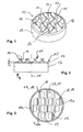
- a first embodiment of a mixer 10 according to the invention is in the FIGS. 1 to 3 shown.
- the mixer 10 is made in a deep-drawing stamping process and has a cup-like shape.
- the mixer 10 has a bottom portion 11 and a side wall portion 12. In the bottom area 11, a plurality of webs 13 run alongside one another without contact, on which tab-like guide elements 14 are formed.
- the guide elements 14 are each alternately and in the longitudinal direction of the webs 13 offset from each other in different directions from the webs 13 from. They are connected along the ridge lines 16 with the webs. Seen in the longitudinal direction of the webs ( FIG. 2 ), the ends of the guide elements 14 are arranged entangled with each other. In the exemplary embodiment shown, the guide elements 14 have a trapezoidal shape tapering towards the free ends, in which the transition areas between the lateral flanks of the guide elements 14 and the end edge are rounded.
- the webs 13 themselves are connected to each other in the bottom region 11 via an edge region 17, which merges rounded into the side wall region 12 formed as a pipe section.
- the mixer 10 is preferably in the direction B ( FIG. 2 ) flows through the one or more fluid streams or streams to be mixed together.
- the surfaces of the guide elements 14 projected into the ground plane are considered to be the swirling surface.
- Web width b and the web thickness S and the material thickness of the mixer are in a ratio of 2: 1 to 1: 1. In these proportions, the guide elements 14 can be clean along the edge lines 16 of the webs 13, without them from their level Be bent out.
- the canted lines 16 and the corresponding web sections are offset parallel to one another and transversely to the web course. In this way, the desired Verschränkungshack is achieved in the folded guide elements 14, which improves the turbulence of the flow passing through.
- the mixer 10 is preferably made of a thermoformable sheet material.
- austenitic steel materials e.g. in qualities such as 1.4301 or similar, in output wall thicknesses of 0.75 to 3 mm.
- the diameter of the illustrated mixer is typically 50 to 75 mm.
- FIGS. 4 and 5 show variants 20 and 30 of the in the FIGS. 1 to 3 illustrated mixer 10th
- the mixer 20 according to FIG. 4 has slightly modified vanes 24, which are curved so that the concave side facing the swirling surface 29 in the flow direction and the curvature about a transverse to the creases 16 from the neck region the guide elements 24 extends to its end extending bending line 25.
- the in FIG. 5 shown mixer 30 also has curved guide elements 34, in which the curvature takes place around the bending line 25. However, it is designed in the other direction, so that here has the convex side with the swirling surface 39 in the flow direction.
- one-dimensional curvature of the guide elements 24 and 34 can also be a two-dimensional curvature or curvature of the guide elements are provided, in which they are then formed more or less spoon-shaped.
- both the shape and size, and the inclination, as well as the curvature of individual guide elements 14, 24 or 34 may be formed individually different.
- the mixing properties can be individually matched to a stationary inflow profile and optimized.
- Fig. 12 shows a mixer 70, the bottom portion 71 is divided into two parts.
- the edge bottom portion 71a includes a rim with outer vanes 74a. These are aligned in the circumferential direction and exposed along radially extending canted lines 76a so that they give a swirl impulse when flowing through the outer edge region of the flow.
- the central bottom portion 71b has transversely extending webs 73 on which the guide elements 74b are formed and arranged similar to those in connection with the Fig. 1, 3rd and 4 described guide elements 14, 24 and 34th
- the outer guide elements 74a can also be issued in pairs starting from a common edge line 76 against each other, so that no swirling action then arises in the edge bottom portion 71a.
- the central bottom portion 71 b may also be formed as in connection with the embodiments according to the Fig. 6 . 7 and 8 will be described below.
- FIG. 6 shows an 11 mixer 40, in which the guide elements 44 are formed like a louver along the entire length of the webs 43. These guide elements 44 are also arched along a bending line 45 that runs parallel to the canted line 46. In this case, the ends of the guide elements 44, which originate from adjacent webs 43, face each other.
- FIG. 7 shows a similar mixer 50, in which the guide elements 54, however, are arranged without additional curvature as grade tabs along the channel lines 56 which extend along the webs 53.
- mixer 60 is provided at each web 63, only a single lamellar guide member 64.
- the guide elements 64 are all oriented in the same direction and issued along the edge lines 66 from the floor area level.
- FIG. 9 shows a mixer assembly 100, in which two mixers 50 are arranged in a pipe section 101.
- the two mixers 50 are here inserted rotated 90 degrees to each other and arranged one behind the other along the flow axis 15.
- the distance of the mixer 50 to each other can be chosen so that an optimal mixing result occurs.
- the sidewall region 52 permits the clean insertion of the mixers 50 into the tube section 101 without tilting the cross-sectional planes (mixing planes) defined by the bottom regions 51.
- mixers can be combined. It is also possible, in addition to the twisted arrangement the mixer 10, 20, 30, 40, 50, 60 with extending in different inclined planes floor areas - so obliquely - to arrange in a pipe section 101.
- mixers are formed without sidewall region.
- Such mixers are then designed more or less disk-shaped, in which only the edge region connects the webs with each other.
- Such a disc-shaped mixer can then for example be placed on a pipe end or inserted between two pipe ends. It is also possible to use such a disk-shaped mixer in a corresponding receiving slot of a pipe section.
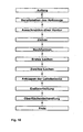
- FIG. 10 shows the sequence of a method for producing the mixer 10.
- a suitable semi-finished product is first provided, which in the present case is a flat sheet metal material, which is provided as a single piece of sheet metal or as a continuous sheet strip (coil material). Then the outer contour is cut out. This can happen mechanically, thermally or abrasive depending on the material used. Suitable working processes are, for example, stamping, plasma cutting or water jet cutting.
- the cup form is produced in a drawing or deep-drawing process, in which the semifinished product is plastically deformed using a die and a male part, so that it comes close to the desired final shape after the molding process.
- the geometry is further approximated. For example, the transition radii between the sidewall region 12 and the bottom region 11 in the edge region 17 are reduced.
- the contours of the webs 13 and the guide elements 14 are defined.
- the two-stage punching has the further advantage that the tool geometries for possibly required punching tools are simplified and the relatively complex web-Leitelementkontur clean and repeatable to produce.
- the guide elements 14 are tilted along the edge lines and deformed relative to the webs 13.
- the individual mixers 10 can be separated from a guide strip required for processing. Possibly. Work can also be done on deburring or calibrating the finished parts. In a final surface treatment, for example, a corrosion protection can be applied.
- the individual work steps can be supplemented by further steps, for example in the case in which the guide elements as in the FIGS. 4, 5 and 6 shown additionally deformed.
- steps are omitted, for example if the mixer is disk-shaped, that is to say without the side wall region 12. In this case, the steps "drag” and "reshape” are eliminated.
- the punching can also be carried out in one stage or together with the "tilting".
Landscapes
- Chemical & Material Sciences (AREA)
- Chemical Kinetics & Catalysis (AREA)
- Engineering & Computer Science (AREA)
- Dispersion Chemistry (AREA)
- Mechanical Engineering (AREA)
- Combustion & Propulsion (AREA)
- General Engineering & Computer Science (AREA)
- Exhaust Gas After Treatment (AREA)
Description
- Die vorliegende Erfindung betrifft einen Mischer zum Vermischen wenigstens eines Fluidstromes in einem Rohrabschnitt. Die Erfindung betrifft weiterhin eine Mischeranordnung, welche wenigstens zwei solcher Mischer aufweist, die hintereinander in einem Rohrabschnitt angeordnet sind und ein Verfahren zur Herstellung eines solchen Mischers.
- Statische Mischer werden verwendet, um einen bzw. mehrere in einem Rohrabschnitt strömende Fluidströme zu verwirbeln bzw. miteinander zu vermischen.
- Der hier verwendete Begriff Fluidstrom soll auch solche Ströme umfassen, bei denen beispielsweise kleine Tröpfchen oder Partikel in einem Fluidstrom transportiert werden.
- Statische Mischer werden z.B. in der Abgasreinigung eingesetzt. Dabei wird in einen Abgasstrom, der in einem Rohrabschnitt strömt (zum Beispiel aus einer Verbrennungsmaschine), über eine Sonde ein Reaktionsmittel injiziert (zum Beispiel Harnstoff zur NOX-Reduktion). Anschließend werden Abgasstrom und Reaktionsmittel einem Katalysator zugeführt, in dem die gewünschte Reaktion zur Abgasaufbereitung stattfindet. Damit eine möglichst vollständige und gleichmäßige Reaktion im gesamten Abgasstrom stattfindet, werden Abgasstrom und Reaktionsmittelstrom vor dem Eintritt in den Katalysator möglichst vollständig miteinander vermischt. Nur so kann das Reaktionsmittel richtig dosiert zugegeben und können die Katalysatorflächen optimal für die Reaktion genutzt werden. Der oder die statischen Mischer sollen dabei auf einer möglichst kurzen Strömungsstrecke Abgasstrom und Reaktionsmittelstrom weitgehend homogen miteinander vermischen und dabei einen möglichst geringen Strömungswiderstand aufbauen. Darüber hinaus spielen gerade im Kraftfahrzeugbereich Kosten und damit fertigungstechnische Aspekte eine große Rolle; das heißt, der statische Mischer soll möglichst kostengünstig herstellbar sein.
- Bei einem aus der
DE 10 2006 024778 B3 bekannten statischen Mischer sind mehrere quer zur Strömungsrichtung aufeinanderliegende Lagen eines wellenförmigen Bandmaterials vorgesehen, das mehrere in Strömungsrichtung durchströmbare Zellen bildet, wobei an der Abströmseite (Austrittsseite der Strömung) der Zellen gewölbte Strömungsleitflächen vorgesehen sind, die sich in Strömungsrichtung sowie quer dazu erstrecken und damit die durch die Zellen geführten Fluidströme miteinander vermischen und verwirbeln. - Ein ähnlicher statischer Mischer ist in
Figur 11 dargestellt. Hier sind gitterförmig gekreuzte, durchströmbare Zellen bildende Blechlamellen vorgesehen, an denen abströmseitig zungenförmige, ebene Strömungsleitflächen vorgesehen sind, die durch die Gitterzellen tretende Fluidströme miteinander vermischen und verwirbeln. Die gitterförmig angeordneten Lamellen sind in einem rohrförmigen Trägerabschnitt fixiert. - Beide Ausführungen stellen wirksame und strömungstechnisch ausgereifte statische Mischer dar. Sie erfordern jedoch einen relativ hohen Fertigungsaufwand und sind damit teuer.
- Aus der
DE 197 41 199 A1 ist ein einfacher aufgebauter, statischer Mischer bekannt, bei dem ein sog. Streckgitter im Rohrquerschnitt eines Strömungskanals angeordnet ist und eine Umströmung der Gitterstreben und Knotenpunkte die Mischung der Fluidströme bewirkende Wirbel und Turbulenzen erzeugt. Für eine verbesserte Vermischung kann ein solches Gitter auch zur Strömungsrichtung geneigt angeordnet werden. Es ist auch vorgesehen, mehrere solcher Gitter hintereinander anzuordnen. Dies kann jedoch strömungstechnisch nachteilig sein, da so unter Umständen ein hoher Druckabfall in der Strömung beim Passieren der Streckgitteranordnung auftreten kann. Damit werden ggf. die Strömungseigenschaften, die insbesondere in der Abgasanlage eines Kraftfahrzeugs genau abgestimmt sein sollen, zu stark gestört. - Aus der
DE 43 13 393 A1 ist eine statische Mischeranordnung bekannt, bei der in quer zur Strömungsrichtung verlaufenden Reihen jeweils mehrere trapezförmige Auslenkelemente angeordnet sind. Die Auslenkelemente sind in jeder Reihe parallel zueinander in die Strömungsrichtung geneigt. Dabei sind jeweils paarweise benachbarte Reihen vorgesehen, deren Auslenkelemente in Längsrichtung zueinander versetzt und entgegengesetzt geneigt sind. Die die Auslenkelemente tragenden Reihen sind jeweils einander berührend Rücken an Rücken zusammengefügt und paarweise in ein Trägergitter eingebaut. Hierbei werden jeweils mehrere Reihen mit Auslenkelementen und Trägergitterelemente zu einem statischen Mischer zusammengefügt. Ähnliche Mischeranordnungen mit quer zur Strömungsrichtung verlaufenden Stegen und daran angeordneten Auslenkelementen sind auch aus derUS 5,605,399 bekannt. - Aus der
DE 35 36 315 A1 ist ein sog. Drallkörper bekannt, bei dem aus einem senkrecht zur Strömungsrichtung stehenden Grundblech Leitschaufeln teilweise ausgestanzt und ausgebogen sind, die in Strömungsrichtung wendelförmig abstehen und in die entstandenen Öffnungen einströmenden Abgasen zusätzlich zu ihrer Strömungsrichtung einen Rotationsimpuls (Drall) verleihen. Solche Drallkörper sind jedoch nur eingeschränkt zur Vermischung zweier Gasströme/Fluidströme geeignet. Der unter Umständen gewünschte Zyklon-Effekt zur Abscheidung im Fluidstrom befindlichen Festkörperteilchen bewirkt nur eine vergleichsweise geringe Vermischung des Fluidstroms. - Eine ähnliche Anordnung ist aus der
WO 03/036056 A1 - Die Aufgabe der vorliegenden Erfindung besteht darin, einen verbesserten statischen Mischer bereitzustellen. Es ist dabei insbesondere wünschenswert, gute Mischeigenschaften, günstige Strömungsverhältnisse und eine konstruktiv bzw. fertigungstechnisch günstige Gestaltung miteinander zu kombinieren.
- Diese Aufgabe erfüllt der Mischer mit den Merkmalen des Anspruchs 1, eine Mischanordnung gemäß Anspruch 8 sowie ein Verfahren zur Herstellung des Mischers gemäß Anspruch 9.
- Der erfindungsgemäße Mischer weist quer zur Strömungsrichtung verlaufende Stege auf, von denen zur Strömungsrichtung geneigte Leitelemente ausgehen. Dabei durchsetzen die Stege den Strömungsquerschnitt ohne einander zu berühren, und die Leitelemente und Stege sind einstückig miteinander verbunden. Ein solcher Mischer erlaubt es, einen einfachen Aufbau mit vergleichsweise günstigen Strömungseigenschaften und einer guten Mischcharakteristik zu kombinieren.
- Dabei wird ein fertigungstechnisch besonders günstiges Press-Präge-Stanz-Bauteil realisiert, das über den Seitenwandbereich zusätzlich stabilisiert wird. Es kann einfach in ein entsprechendes Rohrstück eingeschoben werden, ohne dass es beim Einsetzen verkantet.
- So ein Mischer führt die an sich divergierenden Forderungen nach geringem Druckverlust beim Durchströmen des Mischers, einer wirksamen Durchmischung eines Fluidstroms auf einer kurzen Strecke und einer fertigungstechnisch günstigen und damit kostengünstigen Gestaltung zusammen. Dabei sind jeweils mehrere Leitelemente nebeneinander vorgesehen, so dass zum Vermischen mehrere zungenartiger Leitelemente laschen- oder auch löffelförmig an den Stegen vorgesehen werden können, die unabhängig voneinander entlang ihrer jeweiligen Kantlinie zum Steg verformbar sind. So sind unterschiedlich gestaltete Leitelemente mit unterschiedlichen Neigungen 15° bis 45° an unterschiedlichen Orten im Strömungsquerschnitt realisierbar. Der Mischer kann damit auch an ein bestimmtes Strömungseintrittsprofil angepasst werden. Die Mischungseigenschaften sind über den Strömungsquerschnitt variierbar. Durch Parallel zueinander versetzte Kantlimen wird dieser Effekt weiter verbessert.
- Die Merkmale der Ansprüche 2 bis 5 betreffen dabei fertigungstechnisch und funktional vorteilhafte Lösungen.
- Nach Anspruch 2 sind die Leitelemente jeweils entlang einer Kantlinie mit dem Steg gekoppelt. Damit sind die Bereiche Steg und Leitelement funktional voneinander zu trennen; die Stege bilden die Tragstruktur und die Leitelemente die eigentliche Mischstruktur. Sie können aber dennoch gemeinsam aus einem Stück vorgefertigt (z.B. ausgestanzt) werden. Die Bearbeitung ist dabei mit vergleichsweise einfachen Stanz- und Prägewerkzeugen möglich. Die vorgestanzten Leitelemente können vom Steg entlang der jeweiligen Kantlinie abgekantet werden und mit unterschiedlichen Neigungen in den Fluidstrom angestellt werden.
- Durch eine konvexe oder konkave Ausformung der Leitelemente bezüglich der Strömungsrichtung gemäß Anspruch 3 können zusätzlich positive Strömungseffekte erzielt werden, die den Strömungswiderstand herabsetzen und/oder die Mischeigenschaften verbessern.
- Gemäß Anspruch 4 werden die Ausformungen über entsprechend angeordnete Kantlinien vorgesehen. Diese Gestaltung ermöglicht eine wiederholgenaue Fertigung mit vergleichsweise einfachen Werkzeugen.
- Das in Anspruch 5 angegebene Verhältnis zwischen der Stegbreite und der Stegstärke ist im Hinblick auf die besonders kostengünstige Stanz-Präge-Fertigung vorteilhaft und bietet eine hohe Strukturstabilität.
- Durch den gemäß Anspruch 6 die Stege untereinander verbindenden Randbereich ist ein stabiler Mischer darstellbar, der als komplettes, einstückig herstellbares, scheibenförmiges Bauteil in vorgegebene Rohrquerschnitte einsetzbar ist.
- Die Stege und der Randbereich definieren eine in Strömungsrichtung weisende Stirnfläche und an den Leitelementen sind zur Strömungsrichtung geneigte Verwirbelungsflächen vorgesehen. Nach Anspruch 7 bilden dabei Stirnfläche und die Summe der geneigten Verwirbelungsflächen ein Verhältnis von 0,8 bis 0,35 und bevorzugt ein Verhältnis von 0,5 bis 0,4. Dabei decken Stirnfläche und Verwirbelungsflächen einen Bereich von 50 % bis 75 % des durchströmten Strömungsquerschnitts ab.
- Die Mischanordnung gemäß Anspruch 8 kann die Mischqualität deutlich erhöhen, so dass die Mischlänge, das heißt die erforderliche Länge des Rohrabschnitts, in dem sich die Fluidströme vermischen sollen, verkürzt wird. Dazu können die vorgesehenen Mischer unterschiedlich ausgebildet werden. Es ist aber auch möglich, durch eine unterschiedliche Anordnung baugleicher Mischer zueinander das gewünschte Mischungsergebnis zu verbessern. Dazu können die einzelnen Mischer zur Strömungsrichtung geneigt und/oder in Umfangsrichtung zueinander verdreht angeordnet sein.
- Die Verfahren gemäß der Ansprüche 9 und 10 betreffen besonders günstige und kostensparende Fertigungsverfahren für einen erfindungsgemäßen Mischer.
- Ausführungsbeispiele der vorliegenden Erfindung werden nachfolgend anhand der Zeichnungen erläutert. Dabei zeigt
- Figur 1
- ein erstes Ausführungsbeispiel eines erfindungs- gemäßen Mischers in einer perspektivischen Ansicht,
- Figur 2
- den Mischer aus
Figur 1 in einer Seitenansicht, - Figur 3
- eine Ansicht in Richtung B des in
Figur 1 und 2 dargestellten Mischers, - Figur 4
- ein zweites Ausführungsbeispiel eines erfindungs- gemäßen Mischers in einer perspektivischen Ansicht,
- Figur 5
- ein drittes Ausführungsbeispiel eines erfindungs- gemäßen Mischers in einer perspektivischen Ansicht,
- Figur 6
- einen anderen Mischer in perspektivischer Ansicht,
- Figur 7
- einen anderen Mischer in perspektivischer Ansicht,
- Figur 8
- einen anderen Mischer in perspektivischer Ansicht,
- Figur 9
- eine Schnittdarstellung einer Mischeranordnung mit zwei zueinander verdrehten Mischern gemäß
Figur 7 , - Figur 10
- ein Ablaufdiagramm eines erfindungsgemäßen Herstel- lungsverfahrens,
- Figur 11
- einen aus dem Stand der Technik bekannten Mischer, und
- Fig. 12
- ein siebtes Ausführungsbeispiel eines erfindungs- gemäßen Mischers in perspektivischer Ansicht.
- Ein erstes Ausführungsbeispiel eines erfindungsgemäßen Mischers 10 ist in den
Figuren 1 bis 3 dargestellt. Der Mischer 10 ist in einem Tiefzieh-Stanz-Prägeverfahren hergestellt und hat eine napfartige Gestalt. Der Mischer 10 weist einen Bodenbereich 11 und einen Seitenwandbereich 12 auf. Im Bodenbereich 11 verlaufen nebeneinander, berührungsfrei mehrere Stege 13, an denen laschenartige Leitelemente 14 ausgebildet sind. - Diese Leitelemente sind in einem Winkel von 15° bis 45° zur Strömungsrichtung B geneigt, die parallel zu der in
Figur 2 dargestellten Mittelachse 15 verläuft. Die Leitelemente 14 stehen dabei jeweils wechselweise und in Längsrichtung der Stege 13 zueinander versetzt in unterschiedlichen Richtungen von den Stegen 13 ab. Sie sind entlang der Kantlinien 16 mit den Stegen verbunden. In Längsrichtung der Stege gesehen (Figur 2 ) sind die Enden der Leitelemente 14 miteinander verschränkt angeordnet. Im dargestellten Ausführungsbeispiel weisen die Leitelemente 14 eine sich zu den freien Enden hin verjüngende trapezförmige Gestalt auf, bei der die Übergangsbereiche zwischen den seitlichen Flanken der Leitelemente 14 und der Endkante abgerundet sind. - Die Stege 13 selbst sind im Bodenbereich 11 über einen Randbereich 17 miteinander verbunden, der abgerundet in den als Rohrabschnitt ausgebildeten Seitenwandbereich 12 übergeht.
- Der Mischer 10 wird vorzugsweise in Richtung B (
Figur 2 ) von dem oder dem Fluidstrom oder mehreren Fluidströmen, die miteinander vermischt werden sollen, durchströmt. Dabei steht die in Strömungsrichtung B weisende Stirnfläche 18, die sich aus den entsprechenden Flächenanteilen des Randbereichs 17, der Stege 13 sowie der Ansatzstücke 13a zusammensetzt, in einem Verhältnis zu den ebenfalls in Strömungsrichtung weisenden Verwirbelungsflächen 19 an den Leitelementen 14 von 0,8 bis 0,35 und bevorzugt in einem Verhältnis von 0,5 bis 0,4. Als Verwirbelungsfläche gelten dabei die in die Bodenebene projizierten Flächen der Leitelemente 14. - Stegbreite b und die Stegstärke S bzw. die Materialstärke des Mischers stehen in einem Verhältnis von 2 : 1 bis 1 : 1. Bei diesen Größenverhältnissen lassen sich die Leitelemente 14 sauber entlang der Kantlinien 16 von den Stegen 13 abkanten, ohne dass diese aus ihrer ebenen Anordnung herausgebogen werden.
- Beim Mischer 10 sind die Kantlinien 16 und die entsprechenden Stegabschnitte parallel zueinander und quer zum Stegverlauf versetzt. Auf diese Weise wird bei den abgekanteten Leitelementen 14 das gewünschte Verschränkungsmaß erreicht, was die Verwirbelung der durchtretenden Strömung verbessert.
- Es gibt auch Ausführungen, bei denen die Kantlinien 16 nicht parallel, sondern angewinkelt zueinander verlaufen.
- Der Mischer 10 wird vorzugsweise aus einem tiefziehbaren Blechmaterial hergestellt. Beim Einsatz in einer Fahrzeugabgasanlage sind dazu insbesondere austenitische Stahlwerkstoffe, z.B. in Qualitäten wie 1.4301 o.ä., in Ausgangswandstärken von 0,75 bis 3 mm geeignet. Der Durchmesser des dargestellten Mischers beträgt typischerweise 50 bis 75 mm.
-
Figur 4 und 5 zeigen Varianten 20 und 30 des in denFiguren 1 bis 3 dargestellten Mischers 10. - Der Mischer 20 gemäß
Figur 4 weist leicht modifizierte Leitelemente 24 auf, die so gewölbt sind, dass die konkave Seite mit der Verwirbelungsfläche 29 in Strömungsrichtung weist und die Wölbung um eine quer zu den Kantlinien 16 vom Ansatzbereich der Leitelemente 24 bis zu deren Ende verlaufenden Biegelinie 25 verläuft. - Der in
Figur 5 dargestellte Mischer 30 weist ebenfalls gewölbte Leitelemente 34 auf, bei denen die Wölbung um die Biegelinie 25 erfolgt. Sie ist jedoch in die andere Richtung ausgeführt, so dass hier die konvexe Seite mit der Verwirbelungsfläche 39 in Strömungsrichtung weist. Neben der inFigur 4 und 5 dargestellten eindimensionalen Wölbung der Leitelemente 24 und 34 kann auch eine zweidimensionale Wölbung bzw. Krümmung der Leitelemente vorgesehen werden, bei denen diese dann mehr oder weniger löffelförmig ausgebildet sind. - Bei anderen nicht dargestellten Ausführungen können sowohl die Form und Größe, als auch die Neigung, sowie die Wölbung einzelner Leitelemente 14, 24 oder 34 individuell unterschiedlich ausgebildet sein. Dadurch können die Mischeigenschaften auf ein stationäres Einströmungsprofil individuell abgestimmt und optimiert werden.
-
Fig. 12 zeigt einen Mischer 70, dessen Bodenbereich 71 zweigeteilt ist. Der Randbodenbereich 71a umfasst einen Kranz mit äußeren Leitelementen 74a. Diese sind in Umfangsrichtung ausgerichtet und so entlang radial verlaufender Kantlinien 76a ausgestellt, dass sie beim Durchströmen dem äußeren Randbereich der Strömung einen Drallimpuls geben. Der zentrale Bodenbereich 71b weist quer verlaufende Stege 73 auf, an denen die Leitelemente 74b ähnlich ausgebildet und angeordnet sind, wie die im Zusammenhang mit denFig. 1, 3 und4 beschriebenen Leitelementen 14, 24 und 34. - In einer weiteren nicht dargestellten Ausführungsform können die äußeren Leitelemente 74a auch jeweils paarweise von einer gemeinsamen Kantlinie 76 ausgehend gegeneinander ausgestellt werden, so dass im Randbodenbereich 71a dann keine Drallwirkung entsteht.
- In weiteren nicht dargestellten Ausführungen kann der zentrale Bodenbereich 71b auch so ausgebildet sein, wie er in Verbindung mit den Ausführungsformen entsprechend der
Fig. 6 ,7 und 8 nachfolgend beschrieben wird. -
Figur 6 zeigt eine 11 Mischer 40, bei dem die Leitelemente 44 lamellenartig entlang der Gesamtlänge der Stege 43 ausgebildet sind. Auch diese Leitelemente 44 sind gewölbt und zwar entlang einer Biegelinie 45, die parallel zur Kantlinie 46 verläuft. Dabei sind die Enden der Leitelemente 44, die von benachbarten Stegen 43 ausgehen, einander zugewandt. -
Figur 7 zeigt einen ähnlichen Mischer 50, bei dem die Leitelemente 54 jedoch ohne zusätzliche Wölbung als grade Laschen entlang der Kanlinien 56 angeordnet sind, die entlang der Stege 53 verlaufen. - Beim in
Figur 8 dargestellten Mischer 60 ist an jedem Steg 63 nur ein einziges lamellenartiges Leitelement 64 vorgesehen. Die Leitelemente 64 sind hier alle gleichsinnig orientiert und entlang der Kantlinien 66 aus der Bodenbereichsebene ausgestellt. -
Figur 9 zeigt eine Mischeranordnung 100, bei der zwei Mischer 50 in einem Rohrabschnitt 101 angeordnet sind. Die beiden Mischer 50 sind hier 90 Grad zueinander verdreht eingesetzt und hintereinander entlang der Strömungsachse 15 angeordnet. Der Abstand der Mischer 50 zueinander kann dabei so gewählt werden, dass ein optimales Mischungsergebnis eintritt. Der Seitenwandbereich 52 ermöglicht das saubere Einschieben der Mischer 50 in den Rohrabschnitt 101, ohne dass die durch die Bodenbereiche 51 definierten Querschnittsebenen (Mischebenen) verkanten. - In anderen nicht dargestellten Mischeranordnungen können auch unterschiedliche Mischer miteinander kombiniert werden. Es ist auch möglich, neben der zueinander verdrehten Anordnung die Mischer 10, 20, 30, 40, 50, 60 mit in unterschiedlich geneigten Ebenen verlaufenden Bodenbereichen - also schräg - in einen Rohrabschnitt 101 anzuordnen.
- Es gibt auch weiterhin Ausführungen, bei denen die Mischer ohne Seitenwandbereich ausgebildet sind. Solche Mischer sind dann mehr oder weniger scheibenförmig gestaltet, bei denen nur der Randbereich die Stege untereinander verbindet. So ein scheibenförmiger Mischer kann dann beispielsweise auch auf ein Rohrende aufgesetzt werden oder zwischen zwei Rohrenden eingefügt werden. Es ist auch möglich, so einen scheibenförmigen Mischer in einen entsprechenden Aufnahmeschlitz eines Rohrabschnitts einzusetzen.
-
Figur 10 zeigt den Ablauf eines Verfahrens zur Herstellung des Mischers 10. Dazu wird zunächst ein geeignetes Halbzeug bereitgestellt, welches im vorliegenden Fall ein flaches Blechmaterial ist, welches als einzelnes Blechstück oder als Endlosblechstreifen (Coilmaterial) bereitgestellt wird. Anschließend wird die Außenkontur ausgeschnitten. Dies kann je nach verwendetem Material mechanisch, thermisch bzw. abrasiv geschehen. Geeignete Arbeitsprozesse sind beispielsweise Stanzen, Plasma-Schneiden oder Wasserstrahl-Schneiden. - Die Napfform wird in einem Zieh- oder Tiefziehprozess hergestellt, bei dem unter Verwendung einer Matrize und einer Patrize das Halbzeug plastisch so verformt wird, dass es nach dem Formvorgang der gewünschten Endgestalt nahe kommt. In einem zweiten Nachformvorgang wird die Geometrie weiter angenähert. Zum Beispiel werden die Übergangsradien zwischen dem Seitenwandbereich 12 und dem Bodenbereich 11 im Randbereich 17 verringert.
- Als nächstes werden die Konturen der Stege 13 und der Leitelemente 14 definiert. Durch einen zweistufigen Lochvorgang wird sichergestellt, dass keine unerwünschten plastischen Verformungen der Stege 13 bzw. der Leitelemente 14 erfolgen. Das zweistufige Lochen hat weiter den Vorteil, dass die Werkzeuggeometrien für ggf. erforderliche Stanzwerkzeuge vereinfacht werden und die relativ komplexe Steg-Leitelementkontur sauber und wiederholgenau herstellbar ist.
- Im letzten, die eigentliche Mischergeometrie bestimmenden Arbeitschritt werden die Leitelemente 14 entlang der Kantlinien angekippt und relativ zu den Stegen 13 verformt.
- Zusätzlich können in einer ggf. erforderlichen Endbearbeitung die einzelnen Mischer 10 von einem zur Bearbeitung erforderlichen Führungsstreifen abgetrennt werden. Ggf. können auch noch Arbeiten zum Entgraten oder Kalibrieren der fertigen Teile erfolgen. In einer abschließenden Oberflächenbehandlung kann beispielsweise ein Korrosionsschutz aufgebracht werden.
- Die einzelnen Arbeitsschritte können ggf. um weitere Schritte ergänzt werden, zum Beispiel in dem Fall, in dem die Leitelemente wie in den
Figuren 4, 5 und 6 dargestellt zusätzlich verformt werden. Es gibt auch Fälle, in denen Arbeitsschritte wegfallen, beispielsweise wenn.der Mischer scheibenförmig, das heißt ohne den Seitenwandbereich 12 ausgeführt werden. In diesem Fall fallen die Schritte "Ziehen" und "Nachformen" weg. Bei einfachen Geometrien der Leitelemente (vgl.Fig. 6 ,7, 8 ) kann das Lochen auch einstufig bzw. gemeinsam mit dem "Ankippen" ausgeführt werden. - Weitere Abwandlungen und Variationen der vorliegenden Erfindung ergeben sich für den Fachmann im Rahmen der nachfolgenden Ansprüche.
Claims (10)
- Statischer Mischer (10; 20; 30; 40; 50; 60; 70) zum Vermischen wenigstens eines Fluidstromes über einen Srömungsquerschnitt in einem Rohrabschnitt (101), mit
quer zur Strömungsrichtung verlaufenden Stegen (13; 43; 53; 63; 73) und
von diesen Stegen ausgehenden zur Strömungsrichtung geneigten Leitelementen (14; 24; 34; 44; 54; 64; 74b),
wobei der Mischer (10; 20; 30; 40; 50; 60; 70) einstückig, napfförmig mit einem Bodenbereich (11) und einem in Strömungsrichtung verlaufenden Seitenwandbereich (12) ausgebildet ist, wobei die Stege (13; 43; 53; 63; 73), der Randbereich (17) und die Leitelemente (14; 24; 34; 44; 54; 64; 74a; 74b) einstückig aus dem Bodenbereich (11) ausgebildet sind, dadurch gekennzeichnet, dass jeweils mehrere Leitelemente (14; 24; 34; 44; 54) entlang unterschiedlicher Kantlinien (16; 46; 56) mit einem Steg (13; 43; 53; 73) verbunden sind und die Kantlinien (16) abschnittweise parallel versetzt zueinander verlaufen. - Mischer (10; 20; 30; 40; 50; 60; 70) nach Anspruch 1, bei welchem die Leitelemente (14; 24; 34; 44; 54; 64; 74b) jeweils entlang einer Kantlinie (16; 46; 56; 66) mit einem Steg (13; 43; 53; 63; 73) verbunden sind.
- Mischer (20; 30; 40; 70) nach einem der vorhergehenden Ansprüche, bei welchem die Leitelemente (24; 34; 44; 74b), bezüglich der Strömungsrichtung (B) eine konvexe und/oder konkave Ausformung aufweisen.
- Mischer (20; 30; 40; 70) nach Anspruch 3, bei welchem die Ausformung entlang wenigstens einer weiteren Kantlinie (25; 45) am Leitelement gebildet ist.
- Mischer (10; 20; 30; 40; 50; 60; 70) nach einem der Ansprüche 1 bis 4, bei welchem die Stegbreite (b) in der Scheibenebene und die Stegstärke (S) senkrecht zur Scheibenebene in einem Verhältnis von 2:1 bis 1:1 stehen.
- Mischer (10; 20; 30; 40; 50; 60; 70) nach einem der Ansprüche 1 bis 5, bei welchem die Stege (13; 23; 33; 43; 53; 63; 73) an ihren Enden einstückig mit einem die Stege untereinander verbindenden Randbereich (17) ausgebildet sind.
- Mischer (10; 20; 30; 40; 50; 60; 70) nach einem der Ansprüche 1 bis 6, bei welchem die Stege (13; 43; 53; 63; 73) und der Randbereich (17) eine in Strömungsrichtung weisende Stirnfläche (18) und die Leitelemente (14; 24; 34; 44; 54; 64; 74a; 74b) eine zur Strömungsrichtung (B) geneigte Verwirbelungsfläche (19; 29; 39) definieren, wobei die Stirnfläche (18) zur Verwirbelungsfläche (19; 29; 39) in einem Verhältnis von 0,8 bis 0,35 und bevorzugt in einem Verhältnis von 0,5 bis 0,4 stehen und Stirn- und Verwirbungsfläche (18, 19; 29; 39) gemeinsam 50 % bis 75 % des Strömungsquerschnitts abdecken.
- Mischanordnung (100) mit wenigstens zwei Mischern (10; 20; 30; 40; 50; 60; 70) nach einem der vorhergehenden Ansprüche, welche in Strömungsrichtung hintereinander in einem Rohrabschnitt (101) angeordnet sind,
wobei die Mischer jeweils unterschiedlich ausgebildet und/oder verschieden zueinander ausgerichtet sind. - Verfahren zur Herstellung eines Mischers (10; 20; 30; 40; 50; 60; 70) nach einem der Ansprüche 1 bis 8, umfassend:- Bereitstellen eines Blechwerkstoffs- Ausstanzen einer die Mischergestalt definierenden Außenkontur- Ausformen eines Seitenwandbereichs in einem Tiefziehverfahren zum Ausbilden einer Napfform- erstes Ausstanzen einer Stege und Leitelemente definierenden Innenkontur- Ausformen der Leitelemente entlang der Stege verlaufenden Kantlinien
- Verfahren nach Anspruch 9 zusätzlich aufweisend:- konvexes und/oder konkaves Ausformen der Leitelemente- zur Strömungsrichtung entlang wenigstens einer Biegelinie (25; 45).
Applications Claiming Priority (1)
| Application Number | Priority Date | Filing Date | Title |
|---|---|---|---|
| DE102008020827A DE102008020827A1 (de) | 2008-04-25 | 2008-04-25 | Mischer, Verfahren zur Herstellung eines solchen und Mischeranordnung |
Publications (2)
| Publication Number | Publication Date |
|---|---|
| EP2111917A1 EP2111917A1 (de) | 2009-10-28 |
| EP2111917B1 true EP2111917B1 (de) | 2011-09-28 |
Family
ID=40852104
Family Applications (1)
| Application Number | Title | Priority Date | Filing Date |
|---|---|---|---|
| EP09005543A Not-in-force EP2111917B1 (de) | 2008-04-25 | 2009-04-20 | Statischer Mischer, Verfahren zur Herstellung eines solchen und Mischanordnung |
Country Status (4)
| Country | Link |
|---|---|
| EP (1) | EP2111917B1 (de) |
| AT (1) | ATE526074T1 (de) |
| DE (1) | DE102008020827A1 (de) |
| ES (1) | ES2373842T3 (de) |
Families Citing this family (14)
| Publication number | Priority date | Publication date | Assignee | Title |
|---|---|---|---|---|
| KR101100851B1 (ko) * | 2009-10-29 | 2012-01-02 | 한국전력기술 주식회사 | 환원제혼합 및 소음감쇄 구조를 갖는 배기가스 탈질시스템 |
| US20110174408A1 (en) * | 2010-01-21 | 2011-07-21 | Fluid Components International Llc | Flow mixer and conditioner |
| KR101664494B1 (ko) * | 2010-07-08 | 2016-10-13 | 두산인프라코어 주식회사 | 요소 수용액과 엔진 배기가스의 혼합을 위한 정적 혼합기 |
| JP5124030B2 (ja) * | 2011-03-18 | 2013-01-23 | 株式会社小松製作所 | 排気ガス浄化装置 |
| CA2775346C (en) * | 2011-07-22 | 2019-03-05 | Sulzer Mixpac Ag | Static mixer |
| DE102011083637B4 (de) * | 2011-09-28 | 2016-04-14 | Eberspächer Exhaust Technology GmbH & Co. KG | Misch- und/oder Verdampfungseinrichtung |
| DE102012016423B3 (de) * | 2012-08-21 | 2014-02-27 | Eberspächer Exhaust Technology GmbH & Co. KG | Abgasanlage mit Misch- und oder Verdampfungseinrichtung |
| CN104329142B (zh) * | 2013-07-23 | 2017-04-12 | 埃贝斯佩歇排气技术有限责任两合公司 | 多级板式混合器 |
| CN103585907A (zh) * | 2013-11-20 | 2014-02-19 | 哈尔滨工程大学 | 异形盒式静态混合器 |
| JP6151657B2 (ja) * | 2014-03-20 | 2017-06-21 | ヤンマー株式会社 | 船舶の排気ガス浄化システム |
| DE102016206825A1 (de) * | 2016-04-21 | 2017-10-26 | Man Diesel & Turbo Se | Mischvorrichtung für ein Abgasnachbehandlungssystem einer Brennkraftmaschine |
| EP3287254B1 (de) * | 2016-08-24 | 2022-08-03 | Promix Solutions AG | Mischerstruktur für ein folienwerkzeug und folienwerkzeug |
| CN113083058A (zh) * | 2021-04-21 | 2021-07-09 | 安徽博泰塑业科技有限公司 | 一种ppr的产品原料混合装置 |
| DE102022132126A1 (de) * | 2022-12-05 | 2024-06-06 | Purem GmbH | Abgasbehandlungsanordnung |
Family Cites Families (14)
| Publication number | Priority date | Publication date | Assignee | Title |
|---|---|---|---|---|
| US3444687A (en) * | 1966-03-14 | 1969-05-20 | Louis Andersson | Method and apparatus for afterburning exhaust gases |
| DE2522106C3 (de) * | 1975-05-17 | 1982-04-15 | Bayer Ag, 5090 Leverkusen | Vorrichtung zum kontinuierlichen Mischen fließfähiger Stoffe und Verfahren zum Herstellen eines Mischeinsatzes |
| DE3536315A1 (de) | 1985-10-11 | 1987-04-16 | Sueddeutsche Kuehler Behr | Katalysatoranordnung zur reinigung von abgasen, insbesondere einer brennkraftmaschine |
| DE4313393C2 (de) | 1993-04-07 | 2003-06-26 | Siemens Ag | Statischer Mischer |
| US5605399A (en) * | 1995-10-17 | 1997-02-25 | Komax Systems, Inc. | Progressive motionless mixer |
| ATE250969T1 (de) * | 1997-07-28 | 2003-10-15 | Siemens Ag | Verwendung eines statischer mischers als hydrilysekatalysator sowie dessen verwendung in einer abgasleitung für eine verbrennungsanlage |
| DE19741199C2 (de) | 1997-09-18 | 2000-10-26 | Siemens Ag | Statischer Mischer |
| US6394644B1 (en) * | 1999-06-21 | 2002-05-28 | Koch-Glitsch, Inc. | Stacked static mixing elements |
| GB2381218B (en) * | 2001-10-25 | 2004-12-15 | Eminox Ltd | Gas treatment apparatus |
| DE102006024778B3 (de) * | 2006-03-02 | 2007-07-19 | J. Eberspächer GmbH & Co. KG | Statischer Mischer und Abgasbehandlungseinrichtung |
| DE102006055036B4 (de) * | 2006-11-22 | 2023-03-02 | Faurecia Emissions Control Technologies, Germany Gmbh | Mischelement sowie Abgasanlage für eine Verbrennungskraftmaschine |
| DE102007009890B4 (de) * | 2007-02-28 | 2025-05-28 | Emcon Technologies Germany (Augsburg) Gmbh | Statisches Mischelement sowie Verfahren zur Herstellung eines statischen Mischelements |
| DE102007020812B4 (de) * | 2007-05-04 | 2010-01-14 | Audi Ag | Vorrichtung und Verfahren zur Zudosierung von fluiden schadstoffreduzierenden Medien in einen Abgaskanal einer Brennkraftmaschine |
| DE102007048558A1 (de) * | 2007-10-09 | 2009-04-16 | Audi Ag | Statischer Mischer für eine Abgasanlage eines brennkraftmaschinenbetriebenen Fahrzeugs, insbesondere eines Kraftfahrzeugs |
-
2008
- 2008-04-25 DE DE102008020827A patent/DE102008020827A1/de not_active Ceased
-
2009
- 2009-04-20 ES ES09005543T patent/ES2373842T3/es active Active
- 2009-04-20 EP EP09005543A patent/EP2111917B1/de not_active Not-in-force
- 2009-04-20 AT AT09005543T patent/ATE526074T1/de active
Also Published As
| Publication number | Publication date |
|---|---|
| ATE526074T1 (de) | 2011-10-15 |
| ES2373842T3 (es) | 2012-02-09 |
| DE102008020827A1 (de) | 2009-11-05 |
| EP2111917A1 (de) | 2009-10-28 |
Similar Documents
| Publication | Publication Date | Title |
|---|---|---|
| EP2111917A1 (de) | Statischer Mischer, Verfahren zur Herstellung eines solchen und Mischeranordnung | |
| EP2097625B2 (de) | Mischelement sowie abgasanlage für eine verbrennungskraftmaschine | |
| DE102007009890B4 (de) | Statisches Mischelement sowie Verfahren zur Herstellung eines statischen Mischelements | |
| EP2535535B1 (de) | Statischer Mischer | |
| DE102013204189B4 (de) | Mischsystem | |
| EP2006017B1 (de) | Misch- und/oder Verdampfungseinrichtung und zugehöriges Herstellungsverfahren | |
| DE102007020812B4 (de) | Vorrichtung und Verfahren zur Zudosierung von fluiden schadstoffreduzierenden Medien in einen Abgaskanal einer Brennkraftmaschine | |
| WO2013127955A1 (de) | Vorrichtung zur abgasreinigung | |
| DE102016115030A1 (de) | Abgasmischelement | |
| EP0201665B1 (de) | Wärmeübertrager mit mehreren parallelen Rohren und auf diesen angebrachten Rippen | |
| DE102008017395C5 (de) | Misch- und/oder Verdampfungseinrichtung | |
| WO2013131977A1 (de) | Wabenkörper zur abgasnachbehandlung | |
| DE102019106947A1 (de) | Planetenträger, Verfahren zur Herstellung eines Planetenträgers und Planetengetriebe mit einem Planetenträger | |
| DE102018119578A1 (de) | Mischer | |
| DE102013222914A1 (de) | Verfahren zum Herstellen eines Mischers | |
| DE10009124B4 (de) | Katalysator zur Reinigung eines Abgases einer Verbrennungskraftmaschine | |
| EP0765994A1 (de) | Abgaskrümmer | |
| DE102018125081A1 (de) | Hochdruckgasfilter für Airbag-Gasgeneratoren in Fahrzeugen | |
| EP1382518B1 (de) | Verfahren zur Herstellung eines Karosserie-Blechbauteils | |
| WO2013087850A1 (de) | Mischereinrichtung | |
| DE102012104767A1 (de) | Konischer Wabenkörper mit schräg radial verlaufenden Kanälen | |
| DE102014222395B4 (de) | Abgasanlage und Verfahren zur Herstellung einer solchen | |
| WO2013087852A2 (de) | Mischereinrichtung | |
| EP2226486A1 (de) | Verfahren zur Herstellung eines Ejektor-Düsen-Rohrs | |
| EP2730772B1 (de) | Düse mit Leitvorrichtungen |
Legal Events
| Date | Code | Title | Description |
|---|---|---|---|
| PUAI | Public reference made under article 153(3) epc to a published international application that has entered the european phase |
Free format text: ORIGINAL CODE: 0009012 |
|
| AK | Designated contracting states |
Kind code of ref document: A1 Designated state(s): AT BE BG CH CY CZ DE DK EE ES FI FR GB GR HR HU IE IS IT LI LT LU LV MC MK MT NL NO PL PT RO SE SI SK TR |
|
| 17P | Request for examination filed |
Effective date: 20100419 |
|
| GRAP | Despatch of communication of intention to grant a patent |
Free format text: ORIGINAL CODE: EPIDOSNIGR1 |
|
| RTI1 | Title (correction) |
Free format text: STATIC MIXER, METHOD FOR MANUFACTURING THE SAME AND MIXING ARRANGEMENT |
|
| GRAS | Grant fee paid |
Free format text: ORIGINAL CODE: EPIDOSNIGR3 |
|
| GRAA | (expected) grant |
Free format text: ORIGINAL CODE: 0009210 |
|
| AK | Designated contracting states |
Kind code of ref document: B1 Designated state(s): AT BE BG CH CY CZ DE DK EE ES FI FR GB GR HR HU IE IS IT LI LT LU LV MC MK MT NL NO PL PT RO SE SI SK TR |
|
| REG | Reference to a national code |
Ref country code: GB Ref legal event code: FG4D Free format text: NOT ENGLISH |
|
| REG | Reference to a national code |
Ref country code: CH Ref legal event code: EP |
|
| REG | Reference to a national code |
Ref country code: IE Ref legal event code: FG4D |
|
| REG | Reference to a national code |
Ref country code: DE Ref legal event code: R096 Ref document number: 502009001423 Country of ref document: DE Effective date: 20111222 |
|
| REG | Reference to a national code |
Ref country code: NL Ref legal event code: VDEP Effective date: 20110928 |
|
| PG25 | Lapsed in a contracting state [announced via postgrant information from national office to epo] |
Ref country code: FI Free format text: LAPSE BECAUSE OF FAILURE TO SUBMIT A TRANSLATION OF THE DESCRIPTION OR TO PAY THE FEE WITHIN THE PRESCRIBED TIME-LIMIT Effective date: 20110928 Ref country code: HR Free format text: LAPSE BECAUSE OF FAILURE TO SUBMIT A TRANSLATION OF THE DESCRIPTION OR TO PAY THE FEE WITHIN THE PRESCRIBED TIME-LIMIT Effective date: 20110928 Ref country code: LT Free format text: LAPSE BECAUSE OF FAILURE TO SUBMIT A TRANSLATION OF THE DESCRIPTION OR TO PAY THE FEE WITHIN THE PRESCRIBED TIME-LIMIT Effective date: 20110928 Ref country code: SE Free format text: LAPSE BECAUSE OF FAILURE TO SUBMIT A TRANSLATION OF THE DESCRIPTION OR TO PAY THE FEE WITHIN THE PRESCRIBED TIME-LIMIT Effective date: 20110928 Ref country code: NO Free format text: LAPSE BECAUSE OF FAILURE TO SUBMIT A TRANSLATION OF THE DESCRIPTION OR TO PAY THE FEE WITHIN THE PRESCRIBED TIME-LIMIT Effective date: 20111228 |
|
| REG | Reference to a national code |
Ref country code: ES Ref legal event code: FG2A Ref document number: 2373842 Country of ref document: ES Kind code of ref document: T3 Effective date: 20120209 |
|
| LTIE | Lt: invalidation of european patent or patent extension |
Effective date: 20110928 |
|
| PG25 | Lapsed in a contracting state [announced via postgrant information from national office to epo] |
Ref country code: GR Free format text: LAPSE BECAUSE OF FAILURE TO SUBMIT A TRANSLATION OF THE DESCRIPTION OR TO PAY THE FEE WITHIN THE PRESCRIBED TIME-LIMIT Effective date: 20111229 Ref country code: CY Free format text: LAPSE BECAUSE OF FAILURE TO SUBMIT A TRANSLATION OF THE DESCRIPTION OR TO PAY THE FEE WITHIN THE PRESCRIBED TIME-LIMIT Effective date: 20110928 Ref country code: SI Free format text: LAPSE BECAUSE OF FAILURE TO SUBMIT A TRANSLATION OF THE DESCRIPTION OR TO PAY THE FEE WITHIN THE PRESCRIBED TIME-LIMIT Effective date: 20110928 Ref country code: LV Free format text: LAPSE BECAUSE OF FAILURE TO SUBMIT A TRANSLATION OF THE DESCRIPTION OR TO PAY THE FEE WITHIN THE PRESCRIBED TIME-LIMIT Effective date: 20110928 |
|
| REG | Reference to a national code |
Ref country code: SK Ref legal event code: T3 Ref document number: E 10611 Country of ref document: SK |
|
| REG | Reference to a national code |
Ref country code: IE Ref legal event code: FD4D |
|
| PG25 | Lapsed in a contracting state [announced via postgrant information from national office to epo] |
Ref country code: IS Free format text: LAPSE BECAUSE OF FAILURE TO SUBMIT A TRANSLATION OF THE DESCRIPTION OR TO PAY THE FEE WITHIN THE PRESCRIBED TIME-LIMIT Effective date: 20120128 |
|
| PG25 | Lapsed in a contracting state [announced via postgrant information from national office to epo] |
Ref country code: RO Free format text: LAPSE BECAUSE OF FAILURE TO SUBMIT A TRANSLATION OF THE DESCRIPTION OR TO PAY THE FEE WITHIN THE PRESCRIBED TIME-LIMIT Effective date: 20110928 Ref country code: NL Free format text: LAPSE BECAUSE OF FAILURE TO SUBMIT A TRANSLATION OF THE DESCRIPTION OR TO PAY THE FEE WITHIN THE PRESCRIBED TIME-LIMIT Effective date: 20110928 Ref country code: EE Free format text: LAPSE BECAUSE OF FAILURE TO SUBMIT A TRANSLATION OF THE DESCRIPTION OR TO PAY THE FEE WITHIN THE PRESCRIBED TIME-LIMIT Effective date: 20110928 Ref country code: PT Free format text: LAPSE BECAUSE OF FAILURE TO SUBMIT A TRANSLATION OF THE DESCRIPTION OR TO PAY THE FEE WITHIN THE PRESCRIBED TIME-LIMIT Effective date: 20120130 |
|
| PG25 | Lapsed in a contracting state [announced via postgrant information from national office to epo] |
Ref country code: DK Free format text: LAPSE BECAUSE OF FAILURE TO SUBMIT A TRANSLATION OF THE DESCRIPTION OR TO PAY THE FEE WITHIN THE PRESCRIBED TIME-LIMIT Effective date: 20110928 Ref country code: IE Free format text: LAPSE BECAUSE OF FAILURE TO SUBMIT A TRANSLATION OF THE DESCRIPTION OR TO PAY THE FEE WITHIN THE PRESCRIBED TIME-LIMIT Effective date: 20110928 |
|
| PLBE | No opposition filed within time limit |
Free format text: ORIGINAL CODE: 0009261 |
|
| STAA | Information on the status of an ep patent application or granted ep patent |
Free format text: STATUS: NO OPPOSITION FILED WITHIN TIME LIMIT |
|
| PG25 | Lapsed in a contracting state [announced via postgrant information from national office to epo] |
Ref country code: PL Free format text: LAPSE BECAUSE OF FAILURE TO SUBMIT A TRANSLATION OF THE DESCRIPTION OR TO PAY THE FEE WITHIN THE PRESCRIBED TIME-LIMIT Effective date: 20110928 |
|
| 26N | No opposition filed |
Effective date: 20120629 |
|
| REG | Reference to a national code |
Ref country code: DE Ref legal event code: R097 Ref document number: 502009001423 Country of ref document: DE Effective date: 20120629 |
|
| BERE | Be: lapsed |
Owner name: PRESSWERK STRUTHUTTEN G.M.B.H. Effective date: 20120430 |
|
| PG25 | Lapsed in a contracting state [announced via postgrant information from national office to epo] |
Ref country code: MC Free format text: LAPSE BECAUSE OF NON-PAYMENT OF DUE FEES Effective date: 20120430 |
|
| PG25 | Lapsed in a contracting state [announced via postgrant information from national office to epo] |
Ref country code: BE Free format text: LAPSE BECAUSE OF NON-PAYMENT OF DUE FEES Effective date: 20120430 |
|
| PG25 | Lapsed in a contracting state [announced via postgrant information from national office to epo] |
Ref country code: MK Free format text: LAPSE BECAUSE OF FAILURE TO SUBMIT A TRANSLATION OF THE DESCRIPTION OR TO PAY THE FEE WITHIN THE PRESCRIBED TIME-LIMIT Effective date: 20110928 |
|
| PG25 | Lapsed in a contracting state [announced via postgrant information from national office to epo] |
Ref country code: BG Free format text: LAPSE BECAUSE OF FAILURE TO SUBMIT A TRANSLATION OF THE DESCRIPTION OR TO PAY THE FEE WITHIN THE PRESCRIBED TIME-LIMIT Effective date: 20111228 |
|
| PG25 | Lapsed in a contracting state [announced via postgrant information from national office to epo] |
Ref country code: MT Free format text: LAPSE BECAUSE OF FAILURE TO SUBMIT A TRANSLATION OF THE DESCRIPTION OR TO PAY THE FEE WITHIN THE PRESCRIBED TIME-LIMIT Effective date: 20110928 |
|
| REG | Reference to a national code |
Ref country code: CH Ref legal event code: PL |
|
| PG25 | Lapsed in a contracting state [announced via postgrant information from national office to epo] |
Ref country code: LI Free format text: LAPSE BECAUSE OF NON-PAYMENT OF DUE FEES Effective date: 20130430 Ref country code: CH Free format text: LAPSE BECAUSE OF NON-PAYMENT OF DUE FEES Effective date: 20130430 |
|
| PG25 | Lapsed in a contracting state [announced via postgrant information from national office to epo] |
Ref country code: TR Free format text: LAPSE BECAUSE OF FAILURE TO SUBMIT A TRANSLATION OF THE DESCRIPTION OR TO PAY THE FEE WITHIN THE PRESCRIBED TIME-LIMIT Effective date: 20110928 |
|
| PG25 | Lapsed in a contracting state [announced via postgrant information from national office to epo] |
Ref country code: LU Free format text: LAPSE BECAUSE OF NON-PAYMENT OF DUE FEES Effective date: 20120420 |
|
| PG25 | Lapsed in a contracting state [announced via postgrant information from national office to epo] |
Ref country code: HU Free format text: LAPSE BECAUSE OF FAILURE TO SUBMIT A TRANSLATION OF THE DESCRIPTION OR TO PAY THE FEE WITHIN THE PRESCRIBED TIME-LIMIT Effective date: 20090420 |
|
| REG | Reference to a national code |
Ref country code: AT Ref legal event code: MM01 Ref document number: 526074 Country of ref document: AT Kind code of ref document: T Effective date: 20140420 |
|
| PG25 | Lapsed in a contracting state [announced via postgrant information from national office to epo] |
Ref country code: AT Free format text: LAPSE BECAUSE OF NON-PAYMENT OF DUE FEES Effective date: 20140420 |
|
| REG | Reference to a national code |
Ref country code: FR Ref legal event code: PLFP Year of fee payment: 8 |
|
| REG | Reference to a national code |
Ref country code: FR Ref legal event code: PLFP Year of fee payment: 9 |
|
| REG | Reference to a national code |
Ref country code: FR Ref legal event code: PLFP Year of fee payment: 10 |
|
| PGFP | Annual fee paid to national office [announced via postgrant information from national office to epo] |
Ref country code: CZ Payment date: 20180413 Year of fee payment: 10 Ref country code: DE Payment date: 20180423 Year of fee payment: 10 Ref country code: ES Payment date: 20180523 Year of fee payment: 10 Ref country code: SK Payment date: 20180416 Year of fee payment: 10 |
|
| PGFP | Annual fee paid to national office [announced via postgrant information from national office to epo] |
Ref country code: FR Payment date: 20180424 Year of fee payment: 10 Ref country code: IT Payment date: 20180420 Year of fee payment: 10 |
|
| PGFP | Annual fee paid to national office [announced via postgrant information from national office to epo] |
Ref country code: GB Payment date: 20180424 Year of fee payment: 10 |
|
| REG | Reference to a national code |
Ref country code: DE Ref legal event code: R119 Ref document number: 502009001423 Country of ref document: DE |
|
| GBPC | Gb: european patent ceased through non-payment of renewal fee |
Effective date: 20190420 |
|
| REG | Reference to a national code |
Ref country code: SK Ref legal event code: MM4A Ref document number: E 10611 Country of ref document: SK Effective date: 20190420 |
|
| PG25 | Lapsed in a contracting state [announced via postgrant information from national office to epo] |
Ref country code: DE Free format text: LAPSE BECAUSE OF NON-PAYMENT OF DUE FEES Effective date: 20191101 Ref country code: CZ Free format text: LAPSE BECAUSE OF NON-PAYMENT OF DUE FEES Effective date: 20190420 Ref country code: GB Free format text: LAPSE BECAUSE OF NON-PAYMENT OF DUE FEES Effective date: 20190420 Ref country code: SK Free format text: LAPSE BECAUSE OF NON-PAYMENT OF DUE FEES Effective date: 20190420 |
|
| PG25 | Lapsed in a contracting state [announced via postgrant information from national office to epo] |
Ref country code: FR Free format text: LAPSE BECAUSE OF NON-PAYMENT OF DUE FEES Effective date: 20190430 |
|
| PG25 | Lapsed in a contracting state [announced via postgrant information from national office to epo] |
Ref country code: IT Free format text: LAPSE BECAUSE OF NON-PAYMENT OF DUE FEES Effective date: 20190420 |
|
| REG | Reference to a national code |
Ref country code: ES Ref legal event code: FD2A Effective date: 20200831 |
|
| PG25 | Lapsed in a contracting state [announced via postgrant information from national office to epo] |
Ref country code: ES Free format text: LAPSE BECAUSE OF NON-PAYMENT OF DUE FEES Effective date: 20190421 |