EP2111077A2 - Funkendgerät, Funkkommunikationssystem und Funkkommunikationsverfahren - Google Patents
Funkendgerät, Funkkommunikationssystem und Funkkommunikationsverfahren Download PDFInfo
- Publication number
- EP2111077A2 EP2111077A2 EP09005362A EP09005362A EP2111077A2 EP 2111077 A2 EP2111077 A2 EP 2111077A2 EP 09005362 A EP09005362 A EP 09005362A EP 09005362 A EP09005362 A EP 09005362A EP 2111077 A2 EP2111077 A2 EP 2111077A2
- Authority
- EP
- European Patent Office
- Prior art keywords
- radio
- wake
- timing
- radio terminal
- state
- Prior art date
- Legal status (The legal status is an assumption and is not a legal conclusion. Google has not performed a legal analysis and makes no representation as to the accuracy of the status listed.)
- Withdrawn
Links
Images


Classifications
-
- H—ELECTRICITY
- H04—ELECTRIC COMMUNICATION TECHNIQUE
- H04W—WIRELESS COMMUNICATION NETWORKS
- H04W52/00—Power management, e.g. Transmission Power Control [TPC] or power classes
- H04W52/02—Power saving arrangements
- H04W52/0209—Power saving arrangements in terminal devices
- H04W52/0225—Power saving arrangements in terminal devices using monitoring of external events, e.g. the presence of a signal
- H04W52/0229—Power saving arrangements in terminal devices using monitoring of external events, e.g. the presence of a signal where the received signal is a wanted signal
- H04W52/0235—Power saving arrangements in terminal devices using monitoring of external events, e.g. the presence of a signal where the received signal is a wanted signal where the received signal is a power saving command
-
- H—ELECTRICITY
- H04—ELECTRIC COMMUNICATION TECHNIQUE
- H04W—WIRELESS COMMUNICATION NETWORKS
- H04W52/00—Power management, e.g. Transmission Power Control [TPC] or power classes
- H04W52/02—Power saving arrangements
- H04W52/0209—Power saving arrangements in terminal devices
- H04W52/0212—Power saving arrangements in terminal devices managed by the network, e.g. network or access point is leader and terminal is follower
- H04W52/0216—Power saving arrangements in terminal devices managed by the network, e.g. network or access point is leader and terminal is follower using a pre-established activity schedule, e.g. traffic indication frame
-
- Y—GENERAL TAGGING OF NEW TECHNOLOGICAL DEVELOPMENTS; GENERAL TAGGING OF CROSS-SECTIONAL TECHNOLOGIES SPANNING OVER SEVERAL SECTIONS OF THE IPC; TECHNICAL SUBJECTS COVERED BY FORMER USPC CROSS-REFERENCE ART COLLECTIONS [XRACs] AND DIGESTS
- Y02—TECHNOLOGIES OR APPLICATIONS FOR MITIGATION OR ADAPTATION AGAINST CLIMATE CHANGE
- Y02D—CLIMATE CHANGE MITIGATION TECHNOLOGIES IN INFORMATION AND COMMUNICATION TECHNOLOGIES [ICT], I.E. INFORMATION AND COMMUNICATION TECHNOLOGIES AIMING AT THE REDUCTION OF THEIR OWN ENERGY USE
- Y02D30/00—Reducing energy consumption in communication networks
- Y02D30/70—Reducing energy consumption in communication networks in wireless communication networks
Definitions
- the present invention relates to a radio terminal, a radio communication system, and a radio communication method.
- the radio communication system includes a base station and a plurality of radio terminals and allowing radio communication to be performed by using a predetermined radio band, and the plurality of radio terminals each having a radio interface for performing radio communication with the base station.
- CSMA/CA carrier sense multiple access with collision avoidance
- the order in which the radio terminals transmit their packets is determined randomly.
- the order in which the radio terminals transmit packets is determined by scheduling in the radio network. In scheduling, time (slot) during which a radio terminal transmits a packet is determined for each of the radio terminals. This reduces collision probability of packets transmitted by the radio terminals, allowing radio resources to be effectively used.
- DCF distributed coordination function
- DCF is defined as a communication protocol for a wireless LAN (see, for example, IEEE Standard 802.11, 1999 (R2003) and its amendments, IEEE Press).
- DCF is a protocol for allowing radio terminals to autonomously and distributedly determine their timings to transmit packets.
- enhanced distributed coordination access is defined as a communication scheme using quality of service (QoS) on the basis of DCF (see, for example, I. Aad, P. Hofmann, L. Loyola, J. Wdmer, "Self-organizing 802.11-compatible MAC with Elastic Real-time Scheduling," in proceedings of IEEE MASS 2007, October 2007, Pisa, Italy ).
- the scheduling is performed by a representative one of the plurality of radio terminals (see, for example, IEEE Standard 802.11e, 2005).
- a communication protocol further enhanced based on IEEE 802.11e used in the second technique is proposed.
- the representative radio terminal performs scheduling of a packet transmission order in a real-time application.
- the representative radio terminal transmits a packet for notification of the packet transmission order.
- Each of the radio terminals monitors the packet for notification of the packet transmission order.
- a radio terminal having a power-saving mode to reduce its electric power consumption is known.
- the electric power consumed by the radio terminal is reduced by performing switching from a wake-up state to a sleep state.
- the wake-up state packets can be transmitted and received.
- the sleep state a radio interface in the radio terminal is turned off.
- the following techniques have been proposed as a technique for reducing the electric power consumed by the radio terminal.
- the radio terminal estimates a timing at which a packet will be transmitted or received (called a transmission/reception timing below), and switches from the sleep state to the wake-up state at the transmission/reception timing thus estimated (see, for example, US Patent No. 7,181,190 "Method for maintaining wireless network response time while saving wireless adapter power").
- a MAC protocol based on time division multiple access is proposed. Specifically, the radio interface in the radio terminal is turned off in slots other than the slot used to transmit or receive packets.
- TDMA time division multiple access
- each of the radio terminals monitors a period in which a different radio terminal transmits or receives packets (called a packet transmission/reception period below). Thereby, timings of switching from the sleep-state to the wake-up state are scattered, and accordingly delay is prevented.
- the radio terminal turns off the radio interface in the sleep state.
- the radio terminal in the sleep state cannot monitor the packet for notification of the packet transmission order.
- the radio terminal in the sleep state cannot monitor the packet transmission/reception period of a different radio terminal.
- PCF point coordinating function
- the radio terminal in the sleep state cannot monitor the packet for notification of the packet transmission order.
- the radio terminal in the sleep state cannot discover completion of radio communication of a different terminal. This might lead to a case where the radio resources are not effectively used.
- a radio terminal is in a radio communication system including a radio base station and a plurality of radio terminals and allowing to perform radio communication by using a predetermined radio band, the radio terminal being any one of the plurality of radio terminals.
- the radio terminal includes: a radio interface configured to allow radio communication with the radio base station; a controller configured to control switching between a wake-up state in which the radio interface is turned on and a sleep state in which the radio interface is turned off; and an acquiring unit configured to acquire a reference wake-up timing scheduled as a wake-up timing for switching from the sleep state to the wake-up state. The controller shifts the wake-up timing from the reference wake-up timing.
- the controller shifts the wake-up timing from the reference wake-up timing. This means that the period in which the radio terminal is in the wake-up state is shifted from the scheduled timing. Accordingly, a period emptied after a different radio terminal ends its radio communication can be effectively used. Furthermore, since the reference wake-up timing is previously scheduled, wasteful consumption of electric power can be prevented.
- the acquiring unit acquires the reference wake-up timing from the radio base station.
- the acquiring unit acquires the reference wake-up timing from a representative radio terminal being any one of the plurality of radio terminals.
- the acquiring unit autonomously acquires the reference wake-up timing in an own radio terminal.
- the reference wake-up timing is determined based on a usage state of the predetermined radio band.
- the reference wake-up timing is determined based on a length of time used for radio communication.
- the radio terminal further includes a monitor configured to monitor a usage state of the predetermined radio band in the wake-up state.
- the controller shifts the wake-up timing from the reference wake-up timing, based on the usage state of the predetermined radio band.
- the controller shifts the wake-up timing from the reference wake-up timing, based on QoS information set for the radio communication performed by an own radio terminal.
- the controller shifts the wake-up timing from the reference wake-up timing, based on an error rate of the radio communication performed by an own radio terminal.
- the radio terminal further includes a battery configured to accumulate electric power to be supplied to the radio interface.
- the controller shifts the wake-up timing from the reference wake-up timing, based on a remaining amount of electric power accumulated in the battery.
- the controller controls a shift amount by which the wake-up timing is shifted from the reference wake-up timing.
- the controller controls the shift amount of a next shift, based on the shift amount of a current shift.
- an upper limit is defined for a shift amount by which the wake-up timing is shifted from the reference wake-up timing.
- the controller shifts the wake-up timing from the reference wake-up timing without exceeding the upper limit for the shift amount.
- the controller shifts the wake-up timing which is previously shifted from the reference timing, back to the reference wake-up timing, when the predetermined radio band at the wake-up timing previously shifted is occupied by a different radio terminal.
- the controller shifts the wake-up timing from the reference wake-up timing when a different radio terminal performing radio communication immediately before an own radio terminal has shifted the wake-up timing from the reference wake-up timing.
- a radio communication system includes a radio base station and a plurality of radio terminals each having a radio interface and performing radio communication with the radio base station, and allows radio communication to be performed by using a predetermined radio band.
- the radio communication system includes: a controller configured to control switching between a wake-up state in which the radio interface is turned on and a sleep-state in which the radio interface is turned off; and a setter configured to set a reference wake-up timing scheduled as a wake-up timing for switching from the sleep state to the wake-up state. The controller shifts the wake-up timing from the reference wake-up timing.
- a radio communication method performs radio communication by using a predetermined radio band in a radio communication system including a radio base station and a plurality of radio terminals each having a radio interface configured to allow radio communication with the radio base station.
- the radio communication method including the steps of: (a) controlling switching between a wake-up state in which the radio interface is turned on and a sleep-state in which the radio interface is turned off; (b) setting a reference wake-up timing scheduled as a wake-up timing for switching from the sleep state to the wake-up state; and (c) shifting the wake-up timing from the reference wake-up timing.
- Fig. 1 is a diagram illustrating the radio communication system according to the first embodiment.
- the radio communication system includes a plurality of radio terminals 10 (radio terminals 10A to 10G) and a radio base station 20.
- radio communication is performed using a predetermined radio band.
- the radio communication system is, for example, a wireless LAN communication system or the like.
- the radio communication system employs a radio communication scheme using, for example, carrier sense multiple access with collision avoidance (CSMA/CA).
- CSMA/CA carrier sense multiple access with collision avoidance
- the radio terminal 10 is a terminal constituting of a CPU, a ROM, a RAM, and others.
- the radio terminal 10 is a mobile terminal, a PDA, or the like, and has a function of performing radio communication with the radio base station 20.
- the radio base station 20 is a device constituting of a CPU, a ROM, a RAM, and others.
- the radio base station 20 has a function of performing radio communication with the radio terminal 10.
- Fig. 2 is a block diagram illustrating the radio terminal 10 according to the first embodiment.
- the radio terminal 10 includes a radio interface 11, a battery 12, a remaining battery amount acquiring unit 13, a monitor 14, a scheduling manager 15, and a controller 16.
- the radio interface 11 performs radio communication with the radio base station 20. Specifically, the radio interface 11 performs operation such as transmission and reception of radio waves. Radio waves received by the radio interface 11 include radio waves for not only for its own radio terminal 10, but also for other radio terminals 10.
- States of the radio interface 11 include a wake-up state and a sleep state. In the wake-up state, the radio interface 11 is turned on. In the sleep state, the radio interface 11 is turned off.
- the radio interface 11 transmits a packet including remaining battery amount data, which is described later, to the radio base station 20. Further, the radio interface 11 transmits a packet including user data to the radio base station 20. The radio interface 11 may transmit a packet including both of the remaining battery amount data and the user data to the radio base station 20.
- the radio interface 11 receives a packet including scheduling information from the radio base station 20. Further, the radio interface 11 receives a packet including user data from the radio base station. The radio interface 11 may receive a packet including both of the scheduling data and the user data from the radio base station 20.
- the scheduling information includes a reference timing at which its own radio terminal 10 performs communication.
- the scheduling information includes a reference timing of a slot assigned to its own radio terminal 10.
- Switching from the sleep state to the wake-up state is performed basically at a start timing of a slot assigned to its own radio terminal 10. On the other hand, switching from the wake-up state to the sleep state is performed basically at an end timing of the slot assigned to its own radio terminal 10.
- the scheduling information includes a reference wake-up timing scheduled as a wake-up timing for switching from the sleep state to the wake-up state.
- the scheduling information includes a reference sleep timing scheduled as a sleep timing for switching from the wake-up state to the sleep state.
- the battery 12 accumulates electric power to be supplied to the radio interface 11.
- the battery 12 is, for example, a secondary battery such as a lithium-ion battery.
- the remaining battery amount acquiring unit 13 acquires a remaining amount of electric power accumulated in the battery 12 (such an amount is called a remaining battery amount below).
- the remaining battery amount acquiring unit 13 may quantize the remaining battery amount into values in a predetermined range (e.g., integers from 1 to 4).
- the monitor 14 monitors the usage state of the predetermined radio band. Specifically, the monitor 14 acquires the usage state of the predetermined radio band by monitoring radio waves (particularly for other radio terminals 10) received by the radio interface 11. Accordingly, the monitor 14 monitors the usage state of the predetermined radio band in the wake-up state.
- the scheduling manager 15 manages the scheduling information received from the radio base station 20. Specifically, the scheduling manager 15 manages at least the reference timing at which its own radio terminal 10 performs radio communication. Accordingly, it can be considered that the scheduling manager 15 manages the reference wake-up timing.
- the controller 16 controls the overall operation of the radio terminal 10. For example, the controller 16 performs operations such as setting a radio parameter used in the radio communication. Further, the controller 16 instructs the radio interface 11 to transmit remaining battery data indicating an amount of remaining battery and user data.
- the controller 16 controls switching between the sleep state and the wake-up state, based on the scheduling information managed by the scheduling manager 15. Basically, the controller 16 performs switching from the sleep state to the wake-up state at the start timing (i.e., reference wake-up timing) of the slot assigned to its own terminal 10. The controller 16 performs switching from the wake-up state to the sleep state at the end timing (i.e., reference sleep timing) of the slot assigned to its own terminal 10.
- the controller 16 shifts the wake-up timing for switching from the sleep state to the wake-up state from the reference wake-up timing.
- the sleep timing for switching from the wake-up state to the sleep state may be shifted from the reference sleep timing.
- the wake-up timing shift may be a time shift to before or after the reference wake-up timing.
- the sleep timing shift may be a time shift to before or after the reference sleep timing.
- the controller 16 may shift the wake-up timing from the reference wake-up timing, based on the usage state of the predetermined radio band. Specifically, the controller 16 shifts the wake-up timing from the reference wake-up timing when the usage rate of the predetermined radio band is lower than a predetermined usage rate.
- the controller 16 may shift the wake-up timing from the reference wake-up timing, based on QoS information.
- the QoS information is set according to the radio communication (i.e., the application performing the radio communication).
- the QoS information indicates quality required in the radio communication (the application performing the radio communication). Specifically, the controller 16 shifts the wake-up timing from the reference wake-up timing when the quality indicated by the QoS information is higher than a predetermined quality.
- the controller 16 may shift the wake-up timing from the reference wake-up timing, based on an error rate of the radio communication performed by its own radio terminal 10 (e.g., packet error rate (PER)). Specifically, the controller 16 shifts the wake-up timing from the reference wake-up timing when the error rate is lower than a predetermined error rate.
- PER packet error rate
- the controller 16 may shift the wake-up timing from the reference wake-up timing, based on the amount of remaining battery accumulated in the battery 12 in its own radio terminal 10. Specifically, the controller 16 shifts the wake-up timing from the reference wake-up timing when the remaining battery amount is higher than a predetermined remaining battery amount.
- the controller 16 determines the next wake-up timing when performing switching from the wake-up state to the sleep state. In other words, the controller 16 determines whether to shift the wake-up timing from the reference wake-up timing when performing switching from the wake-up state to the sleep state.
- the controller 16 controls the amount by which the wake-up timing is shifted from the reference wake-up timing (called a shift amount below) for the next time, based on the current shift amount.
- a shift amount is expressed as T PRE (n) where the number of shifts is n.
- T PREV (n+1) C ⁇ T PREV (n).
- C is a constant (such as 2, for example).
- the shift amount increases according to an exponential function taking C n ⁇ 1 as a coefficient.
- F is an increase amount of the shift amount.
- the shift amount increases according to a proportional function taking F ⁇ n as a coefficient.
- an upper limit for the shift amount is defined. To be more precise, it is more preferable to define an upper limit for the amount of shift to before the reference wake-up timing in terms of time and an upper limit for the amount of shift to after the reference wake-up timing in terms of time.
- the controller 16 shifts the wake-up timing from the reference wake-up timing without exceeding the upper limit for the shift amount.
- the controller 16 shifts the wake-up timing from the reference wake-up timing when a different radio terminal 10 performing radio communication immediately before its own radio terminal 10 has shifted the wake-up timing from the reference wake-up timing.
- the controller 16 when having shifted the wake-up timing from the reference wake-up timing and discovering that the wake-up timing in the predetermined radio band is occupied by a different radio terminal 10 at the wake-up timing, the controller 16 returns the wake-up timing which has been shifted from the reference wake-up timing back to the reference wake-up timing.
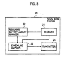
- Fig. 3 is a diagram showing the radio base station 20 according to the first embodiment.
- the radio base station 20 includes a receiver 21, a remaining battery amount manager 22, a scheduling manager 23, and a transmitter 24.
- the receiver 21 receives radio waves from each of the radio terminals 10. Specifically, the receiver 21 receives packets from each of the radio terminals 10. Packets received from each radio terminal 10 include a packet including remaining battery amount data, a packet including user data, a packet including both of the remaining battery amount data and user data, and the like.
- the remaining battery amount manager 22 manages the remaining battery amount of each of the radio terminals 10.
- the scheduling manager 23 determines the reference timing for each of the radio terminals 10 for performing radio communication. For example, what the scheduling manager 23 determines is a reference timing of a time slot assigned to each of the radio terminals 10.
- the scheduling manager 23 determines the reference wake-up timing scheduled as the wake-up timing for switching from the sleep state to the wake-up state. Likewise, it can be considered that, for each of the radio terminals, the scheduling manager 23 determines the reference sleep timing scheduled as the sleep timing for switching from the wake-up state to the sleep state.
- the scheduling manager 23 manages the reference timings of the respective radio terminals 10 for performing radio communication. Moreover, the scheduling manager 23 generates scheduling information indicating the reference timings of the respective radio terminals 10 for performing radio communication.
- the scheduling manager 23 may acquire the usage state of the predetermined radio band, based on the radio waves received by the receiver 21, and determine the reference timings (the reference wake-up timing and the reference sleep timing) of the respective radio terminals 10 for performing radio communication, based on that usage state of the predetermined radio band thus acquired.
- the scheduling manager 23 may determine the reference timings (the reference wake-up timing and the reference sleep timing) of the respective radio terminals 10 for performing radio communication, based on lengths of time used by the respective radio terminals 10 for radio communication.
- the length of time used by a certain radio terminal 10 for radio communication is defined according to an amount of data to be transmitted to that radio terminal 10 and an amount of data to be received from that radio terminal 10.
- the scheduling manager 23 may determine the reference timings (the reference wake-up timing and the reference sleep timing) of the respective radio terminals 10 for performing radio communication, based on the remaining battery amounts of the respective radio terminals 10.
- the transmitter 24 transmits radio waves to each of the radio terminals 10. Specifically, the transmitter 24 transmits packets to each of the radio terminals 10.
- the packets transmitted to the radio terminals 10 include a packet including scheduling information, a packet including user data, a packet including both of the scheduling information and the user data, and the like. (Wake-up Timing Shift)
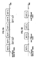
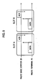
- FIGs. 4A and 4B , 5A and 5B , 6A and 6B , as well as 7A and 7B are diagrams showing the wake-up timing shift according to the first embodiment.
- Slot A is a time slot assigned to the radio terminal 10A.
- Slot B is a time slot assigned to the radio terminal 10B
- Slot C is a time slot assigned to the radio terminal 10C.
- Figs. 4A and 4B a description is given of a case where the wake-up timing is not shifted.
- the start timings of Slots A to C are exactly at their reference wake-up timings.
- the radio terminals 10 are in the wake-up state at the time slots assigned to their own radio terminals 10.
- the radio terminals 10 are in the sleep state at the time slots not assigned to their own radio terminals 10.
- Slot B becomes an empty slot once the radio terminal 10B finishes its radio communication.
- the radio terminals 10A and 10C are in the sleep state during Slot B, so that they cannot discover the existence of an empty slot.
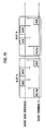
- Figs. 5A and 5B a description is given of a case where the radio terminal 10C shifts its wake-up timing.
- Fig. 5A is the same as Fig. 4B described above.
- the radio terminal 10C makes a time shift of the wake-up timing to before the reference wake-up timing. Note that the shift amount is "T PREV ". By this wake-up timing shift, a period emptied after the radio terminal 10B ends its radio communication is effectively used.
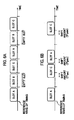
- Figs. 6A and 6B a description is given of a case where the radio terminals 10C and 10A shift their wake-up timings.
- Fig. 6A is the same as Fig. 4B described above.
- the radio terminal 10C makes a time shift of the wake-up timing to before the reference wake-up timing. Note that the shift amount is "T C PREV ". By this wake-up timing shift, the radio terminal 10C can discover that the Slot B is an empty slot. Accordingly, a period emptied after the radio terminal 10B ends its radio communication is effectively used.
- the radio terminal 10A makes a time shift of its wake-up timing to before the reference wake-up timing. Note that the shift amount is "T A PREV ". By this wake-up timing shift, a period emptied after the radio terminal 10C ends its radio communication is effectively used.
- Figs. 7A and 7B a description is given as to amounts to shift the wake-up timings of the respective radio terminals 10A and 10C.
- Fig. 7A is the same as Fig. 4B described above.
- the radio terminal 10C makes a time shift of its wake-up timing to before the reference wake-up timing.
- the radio terminal 10A makes a time shift of its wake-up timing to before the reference wake-up timing.
- Amounts of the n-th shift for the radio terminals 10A and 10C are "T A PREV (n)” and “T C PREV (n)", respectively.
- Amounts of the n+1-th shift for the radio terminals 10A and 10C are "T A PREV (n+1)" and “T C PREV (n+1)", respectively.
- T A PREV (n+1) and T C PREV (n+1) are larger than those of “T A PREV (n)” and “T C PREV (n)”, respectively.
- T PREV (n+1) C ⁇ T PREV (n).
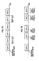
- FIGs. 8 to 11 are diagrams showing examples of the time slot according to the first embodiment.
- the time slot is configured with user data ("DATA”) from the radio terminal 10 to the radio base station 20 and a response (“ACK”) to the user data.
- DATA user data
- ACK response
- the time slot is configured with, in addition to the configuration shown in Fig. 8 , user data ("DATA”) from the radio base station 20 to the radio terminal 10 and a response (“ACK”) to that user data.
- DATA user data
- ACK response
- the time slot is configured with polling information ("PS-POLL") from the radio terminal 10 to the radio base station 20, a response (“ACK") to the polling information, user data (“DATA”) from the radio base station 20 to the radio terminal 10, and a response (“ACK”) to the user data.
- the polling information is information used by the radio terminal 10 to inquire whether or not the radio base station 20 has acquired any user data to its own radio terminal 10 while the radio terminal 10 is in the sleep state.
- the time slot is configured with, in addition to the configuration shown in Fig. 10 , user data ("DATA”) from the radio terminal 10 to the radio base station 20 and a response (“ACK”) to that user data.
- DATA user data
- ACK response
- the controller 16 shifts the wake-up timing from the reference wake-up timing. This means that the period in which the radio terminal 10 is in the wake-up state is shifted from the scheduled timing. Accordingly, a period emptied after a different radio terminal 10 ends its radio communication can be effectively used. Furthermore, since the reference wake-up timing is previously scheduled, wasteful consumption of electric power can be prevented.
- the controller 16 may shift the wake-up timing from the reference wake-up timing, based on the usage state of the predetermined radio band. This prevents unnecessary shift of the wake-up timing, and thereby also prevents wasteful electric power consumption.
- the controller 16 may shift the wake-up timing from the reference wake-up timing, based on the QoS information. Thereby, effective use of radio resources and increase of electric power consumed can be balanced according to the radio communication (the application performing the radio communication).
- the controller 16 may shift the wake-up timing from the reference wake-up timing, based on an error rate of the radio communication performed by its own radio terminal 10 (e.g., packet error rate (PER)). This prevents unnecessary shift of the wake-up timing, and thereby also prevents wasteful electric power consumption.
- PER packet error rate
- the controller 16 may shift the wake-up timing from the reference wake-up timing, based on the amount of remaining battery accumulated in the battery 12 in its own radio terminal
- the controller 16 may control the amount by which the wake-up timing is shifted from the reference wake-up timing (shift amount), based on the number for which the wake-up timing has been shifted from the reference wake-up timing (called the number of shifts below).
- shift amount the number for which the wake-up timing has been shifted from the reference wake-up timing
- an upper limit may be defined for the amount by which the wake-up timing is shifted from the reference wake-up timing (shift amount).
- the controller 16 may shift the wake-up timing from the reference wake-up timing when a different radio terminal 10 performing radio communication immediately before its own radio terminal 10 has shifted the wake-up timing from the reference wake-up timing. Thereby, a period emptied after the different radio terminal 10 shifts its wake-up timing can be effectively used.
- the controller 16 may return the wake-up timing back to the reference wake-up timing. This can prevent unnecessary shift of the wake-up timing from being maintained when there is no empty period.
- the radio base station 20 determines the reference timing at which the radio terminal 10 performs radio communication (i.e., reference wake-up timing) for each of the radio terminals 10. Then, each of the radio terminals 10 acquires its reference wake-up timing from the radio base station 20.
- reference wake-up timing the reference timing at which the radio terminal 10 performs radio communication
- each of the radio terminals 10 acquires its reference wake-up timing from the radio base station 20.
- the embodiment is not limited to this.
- a representative radio terminal may determine the reference timing at which the radio terminal 10 performs radio communication (i.e., reference wake-up timing) for each of the radio terminals 10.
- the representative radio terminal 10 is any one of the plurality of radio terminals 10.
- each of the radio terminals 10 not functioning as the representative radio terminal acquires its reference wake-up timings from the representative radio terminal.
- the radio terminal 10 functioning as the representative radio terminal acquires its reference wake-up timing autonomously within its own radio terminal 10.
- the radio terminals 10 may acquire reference wake-up timings which are randomly set, or reference wake-up timings which are set according to availability of the predetermined radio band.
- each of the radio terminals 10 may autonomously determine the reference timing of its own radio terminal 10 for performing radio communication (i.e., reference wake-up timing). In other words, each of the radio terminals 10 acquires its reference wake-up timing autonomously within its own radio terminal 10.
- the reference timing at which the radio terminal 10 performs radio communication i.e., reference wake-up timing
- the reference timing at which the radio terminal 10 performs radio communication be determined based on the usage state of the predetermined radio band.
- the reference timing at which the radio terminal 10 performs radio communication (i.e., reference wake-up timing) be determined based on the length of time used by each of the radio terminals 10 to perform radio communication.
Landscapes
- Engineering & Computer Science (AREA)
- Computer Networks & Wireless Communication (AREA)
- Signal Processing (AREA)
- Mobile Radio Communication Systems (AREA)
Applications Claiming Priority (1)
| Application Number | Priority Date | Filing Date | Title |
|---|---|---|---|
| JP2008106263A JP4523654B2 (ja) | 2008-04-15 | 2008-04-15 | 無線端末、無線通信システム及び無線通信方法 |
Publications (2)
| Publication Number | Publication Date |
|---|---|
| EP2111077A2 true EP2111077A2 (de) | 2009-10-21 |
| EP2111077A3 EP2111077A3 (de) | 2010-06-16 |
Family
ID=40941938
Family Applications (1)
| Application Number | Title | Priority Date | Filing Date |
|---|---|---|---|
| EP09005362A Withdrawn EP2111077A3 (de) | 2008-04-15 | 2009-04-15 | Funkendgerät, Funkkommunikationssystem und Funkkommunikationsverfahren |
Country Status (4)
| Country | Link |
|---|---|
| US (1) | US8165051B2 (de) |
| EP (1) | EP2111077A3 (de) |
| JP (1) | JP4523654B2 (de) |
| CN (1) | CN101562872B (de) |
Families Citing this family (10)
| Publication number | Priority date | Publication date | Assignee | Title |
|---|---|---|---|---|
| US8346313B2 (en) * | 2006-08-01 | 2013-01-01 | Qualcomm Incorporated | Dynamic warm-up time for a wireless device in idle mode |
| CN101800814B (zh) * | 2009-01-23 | 2013-09-04 | 瑞昱半导体股份有限公司 | 无线通讯装置的电源管理方法及无线通讯装置 |
| WO2010131860A2 (en) * | 2009-05-14 | 2010-11-18 | Lg Electronics Inc. | Method and system for optimizing cpns enabler |
| US20160192305A1 (en) * | 2013-08-08 | 2016-06-30 | Brilliantservice Co., Ltd | Mobile communication terminal, application program for mobile communication terminal, and framework program for mobile communication terminal |
| US9823724B2 (en) | 2014-04-16 | 2017-11-21 | Facebook, Inc. | Power management of mobile clients using location-based services |
| JP6500524B2 (ja) * | 2015-03-17 | 2019-04-17 | 日本電気株式会社 | 無線通信端末装置、および制御方法 |
| JP6595246B2 (ja) * | 2015-07-29 | 2019-10-23 | 株式会社デンソー | 通信システムおよび情報提供装置 |
| US11240756B2 (en) * | 2017-09-28 | 2022-02-01 | Telefonaktiebolaget Lm Ericsson (Publ) | Methods and apparatuses for transmitting a power saving signal |
| US11711764B2 (en) | 2021-02-24 | 2023-07-25 | Nxp B.V. | Autonomous wake on radio scheduler that schedules deterministic radio events to reduce involvement of primary processor |
| KR20240010987A (ko) * | 2022-07-18 | 2024-01-25 | 현대자동차주식회사 | 차량 제어기를 위한 송수신 방법 및 시스템 |
Citations (1)
| Publication number | Priority date | Publication date | Assignee | Title |
|---|---|---|---|---|
| US7181190B2 (en) | 2004-04-30 | 2007-02-20 | Microsoft Corporation | Method for maintaining wireless network response time while saving wireless adapter power |
Family Cites Families (12)
| Publication number | Priority date | Publication date | Assignee | Title |
|---|---|---|---|---|
| US5657317A (en) * | 1990-01-18 | 1997-08-12 | Norand Corporation | Hierarchical communication system using premises, peripheral and vehicular local area networking |
| US6108316A (en) * | 1997-07-25 | 2000-08-22 | At & T Corp | Adaptive scheduling priorities based on battery power level in wireless access protocols |
| US6480476B1 (en) * | 1998-10-15 | 2002-11-12 | Telefonaktiebolaget Lm Ericsson (Publ) | Variable sleep mode for mobile stations in a mobile communications |
| US6804542B1 (en) * | 2000-09-22 | 2004-10-12 | Telefonaktiebolaget Lm Ericsson (Publ) | Sleep modes in peer-to-peer communications |
| CN1204763C (zh) * | 2002-06-25 | 2005-06-01 | 华为技术有限公司 | 无线通信系统中移动终端发送接入请求的方法 |
| JP4016776B2 (ja) * | 2002-09-20 | 2007-12-05 | ソニー株式会社 | 無線通信システム、無線通信装置及び無線通信方法、並びにコンピュータ・プログラム |
| US7130668B2 (en) * | 2003-09-01 | 2006-10-31 | Samsung Electronics Co., Ltd. | Method and system for controlling sleep mode in broadband wireless access communication system |
| US20070160060A1 (en) * | 2004-02-12 | 2007-07-12 | Koninklijke Philips Electronic, N.V. | Method of distributed allocation for a medium access control, a method for re-organizing the sequence devices access a medium, a method for avoiding collision, a method of synchronizing devices in a shared medium and a frame structure |
| US7756548B2 (en) * | 2005-09-19 | 2010-07-13 | Qualcomm Incorporated | Methods and apparatus for use in a wireless communications system that uses a multi-mode base station |
| US7542728B2 (en) * | 2006-02-09 | 2009-06-02 | Altair Semiconductor Ltd. | Dual-function wireless data terminal |
| US7545787B2 (en) * | 2006-02-09 | 2009-06-09 | Altair Semiconductor Ltd. | Simultaneous operation of wireless LAN and long-range wireless connections |
| US8018884B2 (en) * | 2006-06-21 | 2011-09-13 | Qualcomm Incorporated | Low duty cycle network controller |
-
2008
- 2008-04-15 JP JP2008106263A patent/JP4523654B2/ja not_active Expired - Fee Related
-
2009
- 2009-04-15 CN CN2009101320400A patent/CN101562872B/zh not_active Expired - Fee Related
- 2009-04-15 EP EP09005362A patent/EP2111077A3/de not_active Withdrawn
- 2009-04-15 US US12/424,074 patent/US8165051B2/en not_active Expired - Fee Related
Patent Citations (1)
| Publication number | Priority date | Publication date | Assignee | Title |
|---|---|---|---|---|
| US7181190B2 (en) | 2004-04-30 | 2007-02-20 | Microsoft Corporation | Method for maintaining wireless network response time while saving wireless adapter power |
Non-Patent Citations (3)
| Title |
|---|
| ALESSANDRO GIUSTI; AMY L. MURPHY; GIAN PIETRO PICCO: "Decentralized Scattering of Wake-up Times in Wireless Sensor Networks", PROC. OF EWSN, 2007 |
| I. AAD ET AL.: "self-organizing 802.11.-compatible MAC with Elastic Real-time Scheduling", PROCEEDINGS OF IEEE MASS 2007, October 2007 (2007-10-01) |
| ZHIHUI CHEN; ASHFAQ KHOKHAR: "Self Organization and Energy Efficient TDMA MAC", 2004 FIRST ANNUAL IEEE COMMUNICATIONS SOCIETY CONFERENCE ON SENSOR AND AD HOC COMMUNICATIONS AND NETWORKS, 2004 |
Also Published As
| Publication number | Publication date |
|---|---|
| CN101562872A (zh) | 2009-10-21 |
| US8165051B2 (en) | 2012-04-24 |
| CN101562872B (zh) | 2011-12-28 |
| EP2111077A3 (de) | 2010-06-16 |
| US20090257368A1 (en) | 2009-10-15 |
| JP4523654B2 (ja) | 2010-08-11 |
| JP2009260582A (ja) | 2009-11-05 |
Similar Documents
| Publication | Publication Date | Title |
|---|---|---|
| US8165051B2 (en) | Radio terminal, radio communication system, and radio communication method | |
| JP5065977B2 (ja) | 無線端末、無線基地局及び無線通信システム | |
| CN101366247B (zh) | 用于在无线通信网络中调度的方法和设备 | |
| US7881322B1 (en) | Power-saving mechanism for periodic traffic streams in wireless local-area networks | |
| KR101944475B1 (ko) | 무선 통신 시스템에서 전력 소모 감축 | |
| JP5010553B2 (ja) | 無線装置 | |
| US7245946B2 (en) | Optimal power saving scheduler for 802.11e APSD | |
| Chen et al. | Power management for VoIP over IEEE 802.11 WLAN | |
| US20060029024A1 (en) | System and method for battery conservation in wireless stations | |
| JP2009206762A (ja) | 通信端末装置及び受信方法 | |
| EP1578060B1 (de) | WLAN Funkgerät mit Energiesparmodus zur verbesserten Sprachübertragung | |
| US20070041353A1 (en) | Time Management in a Wireless Access Point | |
| EP3537775B1 (de) | Mehrfachzugriffsprotokoll für sehr stromsparende vorrichtungen | |
| Agrawal et al. | Opsm-opportunistic power save mode for infrastructure ieee 802.11 wlan | |
| JP4161988B2 (ja) | ネットワーク内の通信局のエネルギー消費を最適化する方法および通信局 | |
| Lim et al. | Dynamic duty cycle adaptation to real-time data in IEEE 802.15. 4 based WSN | |
| Vigneshwar et al. | Life time maximization analysis with application to LL MAC & RI-MAC protocol in wireless sensor networks | |
| Warshe et al. | Power Management Schemes for WiFi Communication |
Legal Events
| Date | Code | Title | Description |
|---|---|---|---|
| PUAI | Public reference made under article 153(3) epc to a published international application that has entered the european phase |
Free format text: ORIGINAL CODE: 0009012 |
|
| 17P | Request for examination filed |
Effective date: 20090415 |
|
| AK | Designated contracting states |
Kind code of ref document: A2 Designated state(s): AT BE BG CH CY CZ DE DK EE ES FI FR GB GR HR HU IE IS IT LI LT LU LV MC MK MT NL NO PL PT RO SE SI SK TR |
|
| PUAL | Search report despatched |
Free format text: ORIGINAL CODE: 0009013 |
|
| AK | Designated contracting states |
Kind code of ref document: A3 Designated state(s): AT BE BG CH CY CZ DE DK EE ES FI FR GB GR HR HU IE IS IT LI LT LU LV MC MK MT NL NO PL PT RO SE SI SK TR |
|
| AX | Request for extension of the european patent |
Extension state: AL BA RS |
|
| RIC1 | Information provided on ipc code assigned before grant |
Ipc: H04W 56/00 20090101AFI20100507BHEP Ipc: H04W 52/02 20090101ALN20100507BHEP |
|
| 17Q | First examination report despatched |
Effective date: 20160826 |
|
| STAA | Information on the status of an ep patent application or granted ep patent |
Free format text: STATUS: THE APPLICATION IS DEEMED TO BE WITHDRAWN |
|
| 18D | Application deemed to be withdrawn |
Effective date: 20170106 |