EP2110520A2 - Installation de traitement des déchets pour la production d'énergie - Google Patents
Installation de traitement des déchets pour la production d'énergie Download PDFInfo
- Publication number
- EP2110520A2 EP2110520A2 EP09002308A EP09002308A EP2110520A2 EP 2110520 A2 EP2110520 A2 EP 2110520A2 EP 09002308 A EP09002308 A EP 09002308A EP 09002308 A EP09002308 A EP 09002308A EP 2110520 A2 EP2110520 A2 EP 2110520A2
- Authority
- EP
- European Patent Office
- Prior art keywords
- gas
- plant
- furnace
- waste
- connectable
- Prior art date
- Legal status (The legal status is an assumption and is not a legal conclusion. Google has not performed a legal analysis and makes no representation as to the accuracy of the status listed.)
- Withdrawn
Links
Images


Classifications
-
- F—MECHANICAL ENGINEERING; LIGHTING; HEATING; WEAPONS; BLASTING
- F02—COMBUSTION ENGINES; HOT-GAS OR COMBUSTION-PRODUCT ENGINE PLANTS
- F02C—GAS-TURBINE PLANTS; AIR INTAKES FOR JET-PROPULSION PLANTS; CONTROLLING FUEL SUPPLY IN AIR-BREATHING JET-PROPULSION PLANTS
- F02C3/00—Gas-turbine plants characterised by the use of combustion products as the working fluid
- F02C3/20—Gas-turbine plants characterised by the use of combustion products as the working fluid using a special fuel, oxidant, or dilution fluid to generate the combustion products
- F02C3/26—Gas-turbine plants characterised by the use of combustion products as the working fluid using a special fuel, oxidant, or dilution fluid to generate the combustion products the fuel or oxidant being solid or pulverulent, e.g. in slurry or suspension
- F02C3/28—Gas-turbine plants characterised by the use of combustion products as the working fluid using a special fuel, oxidant, or dilution fluid to generate the combustion products the fuel or oxidant being solid or pulverulent, e.g. in slurry or suspension using a separate gas producer for gasifying the fuel before combustion
-
- C—CHEMISTRY; METALLURGY
- C10—PETROLEUM, GAS OR COKE INDUSTRIES; TECHNICAL GASES CONTAINING CARBON MONOXIDE; FUELS; LUBRICANTS; PEAT
- C10J—PRODUCTION OF PRODUCER GAS, WATER-GAS, SYNTHESIS GAS FROM SOLID CARBONACEOUS MATERIAL, OR MIXTURES CONTAINING THESE GASES; CARBURETTING AIR OR OTHER GASES
- C10J3/00—Production of combustible gases containing carbon monoxide from solid carbonaceous fuels
- C10J3/02—Fixed-bed gasification of lump fuel
- C10J3/20—Apparatus; Plants
- C10J3/34—Grates; Mechanical ash-removing devices
- C10J3/36—Fixed grates
-
- F—MECHANICAL ENGINEERING; LIGHTING; HEATING; WEAPONS; BLASTING
- F01—MACHINES OR ENGINES IN GENERAL; ENGINE PLANTS IN GENERAL; STEAM ENGINES
- F01K—STEAM ENGINE PLANTS; STEAM ACCUMULATORS; ENGINE PLANTS NOT OTHERWISE PROVIDED FOR; ENGINES USING SPECIAL WORKING FLUIDS OR CYCLES
- F01K21/00—Steam engine plants not otherwise provided for
- F01K21/04—Steam engine plants not otherwise provided for using mixtures of steam and gas; Plants generating or heating steam by bringing water or steam into direct contact with hot gas
-
- C—CHEMISTRY; METALLURGY
- C10—PETROLEUM, GAS OR COKE INDUSTRIES; TECHNICAL GASES CONTAINING CARBON MONOXIDE; FUELS; LUBRICANTS; PEAT
- C10J—PRODUCTION OF PRODUCER GAS, WATER-GAS, SYNTHESIS GAS FROM SOLID CARBONACEOUS MATERIAL, OR MIXTURES CONTAINING THESE GASES; CARBURETTING AIR OR OTHER GASES
- C10J2300/00—Details of gasification processes
- C10J2300/09—Details of the feed, e.g. feeding of spent catalyst, inert gas or halogens
- C10J2300/0903—Feed preparation
-
- C—CHEMISTRY; METALLURGY
- C10—PETROLEUM, GAS OR COKE INDUSTRIES; TECHNICAL GASES CONTAINING CARBON MONOXIDE; FUELS; LUBRICANTS; PEAT
- C10J—PRODUCTION OF PRODUCER GAS, WATER-GAS, SYNTHESIS GAS FROM SOLID CARBONACEOUS MATERIAL, OR MIXTURES CONTAINING THESE GASES; CARBURETTING AIR OR OTHER GASES
- C10J2300/00—Details of gasification processes
- C10J2300/16—Integration of gasification processes with another plant or parts within the plant
- C10J2300/164—Integration of gasification processes with another plant or parts within the plant with conversion of synthesis gas
- C10J2300/1643—Conversion of synthesis gas to energy
- C10J2300/165—Conversion of synthesis gas to energy integrated with a gas turbine or gas motor
-
- C—CHEMISTRY; METALLURGY
- C10—PETROLEUM, GAS OR COKE INDUSTRIES; TECHNICAL GASES CONTAINING CARBON MONOXIDE; FUELS; LUBRICANTS; PEAT
- C10J—PRODUCTION OF PRODUCER GAS, WATER-GAS, SYNTHESIS GAS FROM SOLID CARBONACEOUS MATERIAL, OR MIXTURES CONTAINING THESE GASES; CARBURETTING AIR OR OTHER GASES
- C10J2300/00—Details of gasification processes
- C10J2300/16—Integration of gasification processes with another plant or parts within the plant
- C10J2300/164—Integration of gasification processes with another plant or parts within the plant with conversion of synthesis gas
- C10J2300/1643—Conversion of synthesis gas to energy
- C10J2300/1653—Conversion of synthesis gas to energy integrated in a gasification combined cycle [IGCC]
-
- C—CHEMISTRY; METALLURGY
- C10—PETROLEUM, GAS OR COKE INDUSTRIES; TECHNICAL GASES CONTAINING CARBON MONOXIDE; FUELS; LUBRICANTS; PEAT
- C10J—PRODUCTION OF PRODUCER GAS, WATER-GAS, SYNTHESIS GAS FROM SOLID CARBONACEOUS MATERIAL, OR MIXTURES CONTAINING THESE GASES; CARBURETTING AIR OR OTHER GASES
- C10J2300/00—Details of gasification processes
- C10J2300/18—Details of the gasification process, e.g. loops, autothermal operation
- C10J2300/1807—Recycle loops, e.g. gas, solids, heating medium, water
- C10J2300/1823—Recycle loops, e.g. gas, solids, heating medium, water for synthesis gas
-
- Y—GENERAL TAGGING OF NEW TECHNOLOGICAL DEVELOPMENTS; GENERAL TAGGING OF CROSS-SECTIONAL TECHNOLOGIES SPANNING OVER SEVERAL SECTIONS OF THE IPC; TECHNICAL SUBJECTS COVERED BY FORMER USPC CROSS-REFERENCE ART COLLECTIONS [XRACs] AND DIGESTS
- Y02—TECHNOLOGIES OR APPLICATIONS FOR MITIGATION OR ADAPTATION AGAINST CLIMATE CHANGE
- Y02E—REDUCTION OF GREENHOUSE GAS [GHG] EMISSIONS, RELATED TO ENERGY GENERATION, TRANSMISSION OR DISTRIBUTION
- Y02E20/00—Combustion technologies with mitigation potential
- Y02E20/12—Heat utilisation in combustion or incineration of waste
-
- Y—GENERAL TAGGING OF NEW TECHNOLOGICAL DEVELOPMENTS; GENERAL TAGGING OF CROSS-SECTIONAL TECHNOLOGIES SPANNING OVER SEVERAL SECTIONS OF THE IPC; TECHNICAL SUBJECTS COVERED BY FORMER USPC CROSS-REFERENCE ART COLLECTIONS [XRACs] AND DIGESTS
- Y02—TECHNOLOGIES OR APPLICATIONS FOR MITIGATION OR ADAPTATION AGAINST CLIMATE CHANGE
- Y02E—REDUCTION OF GREENHOUSE GAS [GHG] EMISSIONS, RELATED TO ENERGY GENERATION, TRANSMISSION OR DISTRIBUTION
- Y02E20/00—Combustion technologies with mitigation potential
- Y02E20/16—Combined cycle power plant [CCPP], or combined cycle gas turbine [CCGT]
- Y02E20/18—Integrated gasification combined cycle [IGCC], e.g. combined with carbon capture and storage [CCS]
Definitions
- the present invention relates to a waste recycling plant and a waste recycling plant module for generating energy from fuel gases. Furthermore, the invention relates to a method for generating electrical energy using the waste recycling plant according to the invention and using the waste recycling plant module according to the invention.
- waste materials in gas generating devices are known by means of heating in the absence of air or by partial combustion under air deficiency. In this way, waste materials can be converted into a recyclable gas as well as into residues.
- From the DE 42 00 341 A1 describes a method for waste gasification to form a non-leachable slag and a gas mixture containing essentially hydrogen and carbon monoxide as combustible constituents, wherein the gasification with the aid of an oxygen-containing gasification medium at temperatures of more than 1200 ° C, preferably in the range of 1300 to 1600 ° C, to take place at an air ratio ⁇ of 0.4 to 0.8 in a cyclone chamber.
- a suitable device for this method is in addition to a cyclone chamber with at least one multi-fluid nozzle, comprising a central tube and a jacket tube, equip. Through the central tube to be gassed waste and a carrier medium to be fed, while on the jacket tube, the gasification medium is introduced.
- From the DE 196 06 575 C2 is a process for the simultaneous material and energy recovery of residual and waste materials refer to, in which the residual and waste materials are thermally pretreated in a pyrolysis reactor by heating to temperatures between 300 and 800 ° C.
- the resulting pyrolysis coke is brought into a fine-grained form, and the resulting pyrolysis gas is condensed out.
- the fine-grained pyrolysis coke, the pyrolysis condensate and the remaining pyrolysis gas are fed to a high or cupola furnace.
- the blast furnace gas leaving the high or cupola furnace may then be used for the combustion and heat demand coverage of the pyrolysis process.
- the DE 198 53 717 C2 discloses a process for gasifying compacted organic materials into a carbon monoxide and hydrogen rich fuel gas.
- fuel bales to be gasified are fed vertically to a fuel inlet channel, which allows a fuel slide to be introduced into a gasifier chamber via a solids slide.
- Most of the oxygen required for gasification is supplied via oxygen lances which are concentrically disposed about the fuel bales present in a slag tank. Further, oxygen is supplied via a secondary supply for the purpose of regulating the temperature. Ignition and pilot burners are used for heating and for putting the carburetor device into operation.
- the raw gas produced during the gasification and the slag are cooled by the injection of water and then discharged.
- From the DE 31 21 206 C2 is a method for gasification of solid waste under pressure in a shaft generator out.
- the optionally held comminuted and / or pelleted wastes are countercurrently dried and gasified in the sump generator by supplying to the hearth a gasifier having at least 40% by volume of oxygen.
- the resulting dusty raw gas is washed and cooled, with resulting dust and condensate-laden cleaning liquid is divided into three fluid flows.
- the second liquid stream is passed after cooling a washing and separation zone.
- the third liquid stream is divided into two further streams, one of which with a portion of the raw gas is burned for the production of energy to be used in the process and wherein the second partial stream is added to the solid waste prior to gasification after receiving by backwashing the filtered solids as sludge.
- the US 3,729,298 relates to a process for the conversion of waste materials into on the one hand gaseous products and on the other hand inert solids.
- a substantially vertical combustion shaft is used, which has a drying zone in the upper part, a thermal decomposition zone in the middle and a combustion and melting zone in the lower part.
- a gas containing at least 40 weight percent oxygen is introduced into the combustion and melt zone such that the weight ratio of oxygen to waste entering the combustion shaft is in the range of 0.15 to 0.128 to 1.
- the waste is gasified in the thermal decomposition zone.
- Most of the solids in the combustion zone are converted to carbon monoxide and hydrogen which generate enough heat during combustion to keep the remaining inorganic solids in a molten state.
- the resulting in the gasifier process gases, especially hydrogen and carbon monoxide are discharged through the drying zone.
- a similar procedure is also used in the US 3,817,724 disclosed.
- a waste recycling plant for generating electrical energy from fuel gases, comprising at least one gasifier furnace having upper, middle and lower sections, in communication with or connectable to said at least one gas compressor, in communication with or connectable to said at least one turbine module comprising at least one combustion chamber and at least one turbine, and in communication with or connectable to the turbine module at least one generator.
- the waste recycling plant according to the invention according to the first embodiment further comprises at least one downdraft device which is connected or connectable on the inlet side with the gasifier furnace and on the outlet side directly or indirectly, with the gas compressor or with a fan unit or with a gas cleaning system.
- the waste recycling plant according to the first embodiment is preferably also equipped with at least one gas cleaning system, which is connected or connectable on the inlet side with the falling stream device or a fan unit and the outlet side with the gas compressor or a fan unit.
- a waste recycling plant for generating electrical energy from fuel gases comprising at least one gasifier furnace with an upper, middle and lower section, in connection or connectable with this at least one Downstream device, in connection or connectable with this at least one gas cleaning system, in connection or connectable with said at least one internal combustion engine and in connection or connectable with this at least one generator, also called second embodiment.
- the waste recycling plants according to the invention are advantageously also equipped with at least one fan unit.
- This fan unit is in a particularly useful Ausgestattung inlet side connected to the gasifier furnace and the outlet side with the falling stream device or connectable before.
- the fan unit can also be connected or connectable on the inlet side with the falling stream device and on the outlet side with the gas cleaning system. Via the fan unit, the removal of gas from the gasifier furnace can be accomplished and controlled and regulated.
- any gasifiable waste can be supplied to the gasification furnace, in particular a cupola furnace, to the recycling plants according to the invention, also unsorted.
- waste is understood here to mean not only conventional domestic or industrial waste, which as a rule contains flammable substances such as wood, food, waste paper and non-flammable substances such as metal and glass, but also other waste or solid fuels such as sawdust, wood chips, Coal, compost, mulch, discarded carpet or carpet residues, hazardous waste of various origins and generally substances containing a combustible or gasifiable organic fraction.
- Carburettor or cupola furnaces are known to the person skilled in the art, for example from the production of cast iron. These are generally shaft furnaces. Suitable cupola ovens go, for example, from DE 31 24 865 A1 . WO 1999/06 03 20 A2 and the DE 690 02 082 T2 out.
- a suitable gasifier or cupola furnace may have a height in the range of 5 to 8 meters and / or with a mean inside diameter in the range of 1 to 5 meters, preferably 1.5 to 4.5 m.
- Cupola ovens can be designed as a co-current and countercurrent furnaces. The latter variant is presently preferred.
- the carburetor or Kupl furnace in particular under oxygen or air exclusion or under extensive oxygen or air exclusion, waste materials via an opening located in the upper region, for example in briquetted form, are supplied.
- the waste recycling plants according to the invention are preferably preceded by at least one briquetting unit.
- Briquetted waste materials may e.g. be kept in a suitable storage bunker so as to ensure a continuous carburetion process.
- the carburetor or cupola furnace also with an oxygen system containing z. Oxygen lances, to be used e.g. To release blockages inside the carburetor.
- These shutters are designed and suitable to prevent the escape of gases from the carburetor or cupola furnace and the entry of air or oxygen into the carburetor or cupola furnace.
- waste recycling plants according to the invention which are additionally equipped with at least two valves, which are capable, in particular in the filling of the Carburetor or cupola furnace to form a lock
- the inventive method can be performed particularly efficient.
- the lower slide is closed, for example, you open the upper slide.
- the upper slide can be closed, whereupon the lower slide can be opened releasing the waste materials into the carburetor or cupola furnace. This lock ensures that no substantial amounts of gas can escape from the gasifier or cupola furnace.
- the closure units which come into consideration for the systems according to the invention that the lower closure unit is set up and suitable for carrying waste quantities in the closed state and being able to release them into the interior of the oven when the upper second closure unit is closed.
- the upper portion of the gasifier furnace generally identifies that portion where the waste material is introduced into the furnace interior.
- the lower portion of the gasifier furnace generally comprises the area in which the burner units are present or attachable and extends regularly to the support unit for the support of the waste to be gasified, which is preferably in the form of a grid.
- the middle section of the gasification furnace generally then extends between the support unit or the grate and the upper section and is regularly that region in which at least the majority of the waste material to be gasified is present.
- the upper section of the gasifier furnace points advantageously a larger diameter than the adjoining portion of the gasification furnace. This upper section of the larger diameter gasification furnace is preferably filled with garbage to be gassed during driving of the gasification furnace, at least in its lower region, in order to obtain a larger surface over which the combustion gases produced can escape.
- the carburetor or cupola furnace in a preferred embodiment has a liquid-cooled waste support device, in particular in the form of a liquid-cooled grid.
- a liquid-cooled waste support device in particular in the form of a liquid-cooled grid.
- the support device or the grid On this support device or on this grid or on resting on these bars fireclay bricks, for example in spherical form, reach the gasified waste materials to support.
- the support device or the grid the support device or the grating may be partially or completely formed from tubes through which cooling liquid can be passed if necessary.
- the support device or the grid is preferably designed in such a way that inorganic residues such as slags, metals or metal oxides in z. Liquid, viscous or solid form by e.g.
- the rods in particular the rods designed for the passage of cooling liquid, are parallel and / or can, in particular individually, be exchanged.
- the carburetor or cupola furnace has at least one burner unit in the lower section, preferably below the waste support device or grid.
- the utilization plants according to the invention have at least two, in particular at least three burner units. Of course, five, seven or more burner units can be used.
- the carburetor or cupola furnace can be equipped at least in sections with cooling, for example by means of a jacket with cooling coils.
- the middle portion for example, the portion lying between the grate and the filling end of the carburetor or cupola furnace, is cooled.
- the middle and in particular the lower section of the carburetor or cupola may at least partially be lined with fireclay bricks.
- the temperature of the combustion gas removed in the gasification furnace is to be reduced via an expansion and / or liquid spray cooling.
- Suitable falling stream devices accordingly have at least one expansion region. In this area, the volume available to the combustion gas expands.
- a quench can also be used for cooling and pre-purifying the combustion gas.
- the falling stream device is preferably connected via a pipeline in the upper section, in particular in the region of the filling end of the carburetor or cupola furnace with this.
- This connection line preferably starts in the area of the upper section which is not regularly filled with waste materials when driving the gasification furnace.
- This section is preferably provided with a larger diameter in relation to the middle section of the gasifier or cupola furnace, so that the combustion gases produced in the furnace can escape or be removed over a larger surface area.
- the falling-stream device is supplied with the gas produced in the carburetor or cupola furnace during the carburizing process.
- the downdraft device is accordingly on the inlet side with the gasifier furnace and on the outlet side mostly, directly or indirectly, with a Gas compressor or connected to a fan unit or with a gas cleaning system or connectable.
- a heat extraction unit is provided between the carburetor or cupola furnace and the downdraft device.
- the temperature of the gas mixture removed from the gasifier or cupola furnace can be reduced to, for example, temperatures in the range from 350 to 400.degree.
- gases having a temperature in the range from 400 to 500.degree. C., for example 420.degree. C. are removed from the gasifier or cupola furnace.
- at least one further heat extraction unit may be provided between the gasifier furnace and a gas compressor.
- connection between the individual components of the waste recycling plant according to the invention can be prepared in each case via suitable, familiar to the expert piping.
- the gasifier furnace itself or the line connecting the furnace and the downdraft device may also be connected or connectable to a drain.
- the components connected downstream of the furnace can not be properly operated, for example, they are defective, it has proved to be advantageous to remove the combustion gas and optionally to neutralize a purification unit and / or a combustion unit supply.
- a suitable downdraft device the gas taken from the carburetor or cupola enters through this through an upper opening.
- liquid is sprayed via at least one nozzle, advantageously above the expansion region of the downdraft device, preferably opposite to the direction of entry of the gas.
- a suitable downdraft device can also have a plurality of successive expansion areas.
- anyone can do this Expansion area be equipped with one or more nozzles for spraying liquid.
- suitable mixers are also provided with which surfactants are mixed into the aqueous liquids to be fed into the falling stream device.
- the temperature of the liquids to be fed into the downdraft device may be, for example, at room temperature or below.
- Such downdraft devices accordingly have a cross-sectional enlargement following the inlet region.
- the expansion of the gas causes a considerable temperature reduction over a very short distance.
- the temperature of the gas may be reduced to values in the range of 50 to 100 ° C, for example to about 60 ° C.
- the temperature reduction in the falling-stream device is due in a preferred embodiment both to aerodynamic effects and to the injected aqueous liquid.
- Suitable downdraft devices can be found for example in the EP 0 972 556 A1 described.
- the resulting in the falling stream device sludge content can be removed from the unit and fed back to the carburetor or cupola according to a variant. This happens, for example, in such a way that first of all the liquid fraction containing solids settling in the lower region of the falling stream device is transferred to a settling tank and the sedimented solid particles can be sedimented therein.
- pre-cleaning of the combustion gas mixture regularly occurs to the extent that soot particles and resin components, for example high molecular weight hydrocarbons, are separated off.
- Suitable gas purification systems comprise in one embodiment at least one roller scrubber (variant II).
- roller scrubbers are known to the person skilled in the art.
- Suitable roller scrubbers are, for example, drums, which are equipped with a multiplicity of openings. With the help of roller scrubbers, a very thin aqueous liquid film is generated, which emerges due to its large surface in interaction with the dirt particles of the gas to be cleaned. The cleaning effect can be further increased by the addition of surfactants to the washing liquid.
- the gas purification system has at least one spray nozzle for generating a liquid mist or aerosol (variant III).
- suitable gas purification plants operate according to the so-called mist process, in which an aqueous system is finely atomized into the gas stream by means of at least one nozzle. Any particulate dust particles and other finely divided solids are ad- or absorbed at the individual water droplets of the aerosol formed. The water droplets loaded with these solids can be suitably trapped in a so-called demister.
- the demister suitably constitutes a woven fabric, in particular plastic fabric, preferably with intersecting threads.
- the spray nozzles used in the gas purification plant are generally designed to produce average droplet sizes in the range of 3 to 100 microns, especially from 5 to 70 microns.
- the droplet size of the aerosol generated in the gas purification plant is particularly preferably in a range of 5 to 40 microns, for example in a range of 5 to 30 microns.
- the aqueous system can be fed via suitable injection nozzles, for example at a pressure of 60 bar, in the gas purification system, preferably mixed with surfactants such as surfactants.
- Suitable aerosols may also include, for example, so-called mixed mist, in which droplets of aqueous systems that are equipped with different, for example opposing, chemical properties are present.
- a first aqueous system have an acidic pH and a second aqueous system have a basic pH, with the result that present in the aerosol droplets with acidic and basic properties side by side.
- Such aerosols or mixed mist and processes for their preparation can be DE 195 45 679 A1 be removed.
- the gas leaving the gas purification plant regularly has a temperature in the range of 30 to 70 ° C, for example in the range of 35 to 55 ° C. Also, the resulting in the gas purification plant sludge can in turn be supplied to the carburetor or cupola furnace.
- a gas purification system can be provided as a gas purification system, a cyclone for dry separation of solid constituents from the fuel gas escaping the gasifier, the inlet side connected to the gasifier and the outlet side directly or indirectly connected to the gas compressor (variant I).
- the purified gas mixture may be supplied to an air mixer in another embodiment to produce an optimized combustion gas mixture.
- purified gas and air are mixed in equal parts in the air mixer.
- the gas mixture preferably the gas / air mixture obtained via the air mixer, enters the gas compressor, in which the gas is compressed.
- the compressed gas or the compressed gas / air mixture can then be supplied to a combustion chamber or a turbine module comprising this combustion chamber for the purpose of generating electrical energy.
- the air compressor is accordingly set up and suitable for feeding compressed air into the combustion chamber and / or a line from the gas compressor to the turbine module, in particular the combustion chamber.
- the turbine module comprises at least one combustion chamber and at least one turbine or a turbine runner.
- the compressed gas or gas mixture is preferably burned at temperatures in the range of 2000 to 3000 ° C.
- the turbine module comprises a positive displacement rotary turbine, such as in the DE 31 49 040 described.
- a positive displacement rotary turbine such as in the DE 31 49 040 described.
- Such usually equipped with a housing and an output shaft turbine modules have in a particularly advantageous embodiment of an elliptical, divided by a concentrically mounted rotor in two opposing radial chambers interior and at least two groups each eccentrically and radially displaceable in the rotor and rotating with the rotor , A friction-free seal over the two radial chambers bounding the inner wall causing rotor blades, as well as further inlets and outlets.
- turbines which are used in the EP 432 287 A1 are described.
- These are positive displacement gear pump or gear motor rotary or percussion gear pump or gear motor type rotary piston machines with a housing having means defining at least one internal cavity.
- This inner cavity is preferably divided into a plurality of mutually aligned and partially overlapping cylinder chambers, which together form a chamber group.
- in the housing there may be a corresponding plurality of adjacent shafts which are rotatably mounted in the housing, each of these shafts being parallel to the other shafts and arranged substantially centrally in each of these chambers.
- the housing preferably includes means having at least two inlet channels and at least two Form outlet channels for insertion or discharge of a working medium into or out of the chamber group.
- This chamber group has a first rotor fixed to a central shaft of this plurality of shafts.
- the first rotor has an outer surface, to which a plurality of pressure blades are fixed, extending in the longitudinal direction thereof and are arranged radially spaced from each other.
- This group of chambers further receives a plurality of slot rotors mounted on the shafts adjacent to the central shaft, each slot rotor being located in closest proximity to the first rotor and having a plurality of grooves on its outer surface radially spaced therefrom according to the spacing of these pressure blades are attached from each other.
- Each of these grooves has a shape for receiving one of these pressure vanes to allow engagement of the pressure vanes in these grooves during rotation of the first rotor and the slot rotor.
- Generators for power generation which are connected or connectable to an output shaft of a turbine, are known in the art.
- a suitable embodiment of a waste recycling plant comprises a gasification furnace, in connection or connectable with at least one gas compressor, and this gas compressor, in conjunction or connectable with at least one turbine module, and this turbine module, comprising at least one combustion chamber and at least one positive displacement rotary turbine in particular comprising an elliptical interior divided by a concentrically mounted rotor into two radially chambers arranged opposite each other and at least two groups each eccentrically and radially displaceable in the rotor and rotating with the rotor, a frictionless seal over the rotor walls bounding the two radial chambers, and further inlets and outlets.
- the positive-displacement gear pump or gear-motor rotary piston machines or positive-displacement gear pump or gear motor-like rotary piston machines described in detail above can also be used.
- an air compressor compressed air is fed into the supply line and / or directly into the combustion chamber.
- waste recycling plants comprising at least one gasifier furnace, at least one downflow device, at least one gas compressor, optionally at least one air compressor, and a turbine module, comprising at least one combustion chamber and at least one turbine, and a generator.
- the two variants of suitable waste recycling plants described above can additionally be equipped with a gas purification plant which is present between the falling stream device and the gas compressor.
- Inventive waste treatment plants in particular those according to the first embodiment, further have in a further advantageous embodiment, at least one connected to the combustion chamber or connectable unit for feeding water vapor. In this way, additional power is released at the high temperatures in the combustion chamber.
- the pressure generated in the combustion chamber is converted into rotary motion via the turbine or the turbine wheels.
- the generated torque can then be transmitted to a generator.
- a condenser downstream of and in communication with the turbine, which is arranged and adapted to separate gas escaping water from the turbine module.
- a particularly expedient embodiment of the aforementioned embodiment comprising the feeding of water vapor into the combustion chamber, further provides at least one heat exchanger in operative connection with the combustion chamber of the turbine module.
- This heat exchanger removes the resulting exhaust gas during combustion heat energy, with the help of which then the water vapor can be generated, which is introduced into the combustion chamber.
- the heat exchanger e.g. the trapped in the condenser water, which may have previously undergone a water treatment unit, are converted into water vapor.
- a further development of the waste recycling plants according to the invention further provides a subsequent to the turbine module or the internal combustion engine and connected to at least one burner unit of Vergaserofens or connectable lines, which is adapted and suitable for supplying at least a portion of the combustion gases from the turbine module or the internal combustion engine to at least one burner unit. In this way, the residual oxygen content contained in the combustion gas can be supplied to a further use.
- a waste recycling plant module comprising at least two waste recycling plants, and by a waste recycling plant module comprising at least two plant lines, each comprising at least one gasifier furnace, in connection or connectable with this at least one falling stream device, in connection or connectable with this possibly at least one gas cleaning plant, in connection or connectable to the falling-stream device or the gas-cleaning plant, at least one gas compressor and in connection or connectable with this at least one turbine module, comprising at least one Combustion chamber and at least one turbine, wherein at least two, in particular all, plant lines each have a separate generator in conjunction or connectable to the turbine module or wherein the turbine modules at least one or more system lines can also be replaced by one or more engines.
- Individual components of these lines are preferably in operative connection with each other.
- at least two systems or system lines can be connected or connectable via at least one bypass line.
- a redundant recycling plant module is created, with the problem of possible downtime can be further reduced.
- the components of the system lines mentioned correspond in their specific and general embodiments to the above-described components of the utilization plants according to the invention.
- the waste recycling plant module has at least one first bypass line from the gasifier furnace of a first plant line or plant to the falling stream device of a second plant line or plant, at least one second bypass line from the falling stream device of a first plant line or plant to the gas purification plant and / or the gas compressor of a second plant line or plant, at least a third bypass line from the gas purification system of a first plant line or plant to the gas compressor a second plant line or plant and / or at least a fourth bypass line of the Gas compressor of a first plant line or plant to the turbine module of a second plant line or plant.
- Particularly high environmental standards is such a waste recycling plant invention, in which that the Brikettieriki, the waste storage, the gasifier, in particular the filling of the gasification furnace, the downdraft device, the fan unit and / or the gas cleaning system are connected to at least one air purification system or included.
- the components mentioned here can under a low Be kept under negative pressure, so that it ensures that no odor nuisance or other hazards to the environment.
- the object underlying the invention is achieved by a method for generating electrical energy from waste using waste recycling plants according to the invention, wherein the waste, in particular in briquetted form, in the gasification furnace under oxygen-poor conditions, especially at temperatures in the range from 40 ° C to 2400 ° C, resulting gas, especially at a temperature not higher than 600 ° C, taken from the gasification furnace and fed to the falling stream device, brought in the falling stream device, the temperature of the gas to less than 100 ° C, optionally, the gas thus cooled is fed to a gas cleaning plant, the gas in the gas cleaning plant is exposed to a liquid spray, optionally the gas cleaned in the gas purification plant or the gas taken from the falling stream is compressed in a compressor and the optionally compressed gas of a Br ennhunt a turbine module or an internal combustion engine fed and burned therein, preferably in the presence of water vapor, and that the energy released in the combustion chamber or the internal combustion engine is passed through the turbine module to a generator for generating electrical energy
- the method is operated in such a way that only gas is taken from the gasifier or cupola furnace whose oxygen content is not above 5%, preferably not above 4%.
- the temperature above the grid can be selected such that it does not exceed 1200 ° C., in particular not 1100 ° C.
- the maximum temperature in the gasification furnace is usually reached in the area of the burners below the grid. If necessary, the temperature above the grid can also be significantly above 1100 ° or 1200 ° C, for example, to avoid the clogging of the gasification furnace.
- the present invention is based on the surprising finding that gasifiable waste can be utilized in a series connection of suitable and coordinated system components with high energy exploitation, whereby at the same time a high degree of process and environmental safety can be ensured.
- the waste recycling plant 1 has a briquetting unit 2, to which the waste can be supplied for the purpose of compaction and portioning.
- the Brikettierussi 2 may also be preceded by a crushing plant to facilitate the Brikettiervorgang.
- the briquetted waste is first fed to a storage bunker 4 which, for example, can have a take-up capacity of 1000 tons.
- the transport of the briquetted waste units can be carried out either by means of conveyor belts or by means of the illustrated movable crane 6.
- the briquetted waste passes through the crane 6 via the filling unit 8 in the form of an insertion tube into the carburetor or cupola 10.
- the cupola 10 is designed as a vertical shaft furnace, the lower Region 12 via a liquid-cooled grate 14 and a plurality of burner units 16 has.
- the burner 16 12 temperatures of eg 1800 to 2400 ° C, suitably set from about 2100 ° C in the lower part become.
- the present in the upper portion 18 of the cupola furnace 10 filling unit 8 has two vertically spaced from each other arranged shutter slide 20 to 22, which independently of each other, the insertion tube 8 close and can open and form an introducer 24.
- the shutter slide 20 and 22 serve to let the cupola furnace 10 resulting combustion gases escape from this. Furthermore, it should be prevented with their help an air inlet during the carburetor process in the cupola furnace.
- the central portion 26 can be cooled via a cooling unit 28 if necessary.
- the resulting in the cupola furnace 10 combustion gas is supplied via a line 30 attaching in the upper portion 18 of the falling-stream device 32.
- the carburetor or cupola furnace is always filled to above the middle section 26 (indicated by dashed line), ie, into the widened upper section 18.
- the high heat energy contained in the gas removed from the cupola furnace can be withdrawn via a heat extraction unit 34 connected to the conduit 30.
- the falling stream device 32 in which the still very hot gas mixture is expanded under cooling, can also be injected for further cooling, a water mist, preferably opposite to the feed direction of the gas.
- the relaxed, cooled gas mixture is fed via a line 36 to a gas purification system 38.
- a fan unit 40 can be used.
- resulting sludge can be supplied to the cupola, for example, for further use, for example via separate lines (not shown).
- gaseous components in the gas cleaning enter the water used, this can be intercepted when the water is purified and used for example for the operation of the burner 16.
- the gas mixture purified in the gas purification system 38 is compressed in the illustrated embodiment before entering the turbine module 44 in the high-pressure compressor 42.
- the gas mixture is supplied to the high-pressure compressor 42 via the line 46.
- the purified gas mixture is first supplied to an air mixer 48 before it enters the high-pressure compressor 42 (dashed line).
- the turbine module 44 has a combustion chamber, a heat exchanger, a turbine and a condenser.
- a combustion chamber not only the highly compressed gas mixture or air / gas mixture, but also steam is fed via a corresponding nozzle or a corresponding inlet into the combustion chamber.
- the exhaust gas escaping from the combustion chamber can be further energetically used by using a further heat extraction unit 52 before it is optionally fed to a purification unit 54 and a condenser 56 via corresponding pipelines.
- the torque generated in the turbine module is converted via the generator 58 into electrical power.
- the method according to the invention for recycling waste with the aid of the illustrated utilization plant is such that the cupola furnace 10 is set up to gasify about 4 to 5 tons of waste, preferably in briquetted form, per hour.
- a temperature of, for example, up to 2400 ° C is maintained by means of the burner 16 in the lower portion 12 of the cupola furnace 10.
- the furnace wall can be cooled with the aid of the cooling unit 28, in this way to control the maximum temperature in the furnace interior.
- briquetted waste is applied in the illustrated variant via the crane 6 with the upper closure slide 20 open on the closed closure slide 22.
- the upper shutter slide 20 of the lock unit 24 is closed, whereupon the lower shutter slide 22 is opened by releasing the waste to be gasified.
- the falling through the liquid-cooled grid 14 residues such as slags or metals can be removed from the lower part of the cupola furnace 10 and fed to a further recovery or landfill.
- the cupola furnace 10 is driven in such a way that the combustion gases produced in the gasification in the upper section 18 via the above the waste line 30 at a temperature in the range of 400 to 450 ° C, for example 420 ° C. , can be taken.
- an example valve-controlled line 60 may be provided, which differs from the the gas-removing lines 30 branches off and serves to allow the gas formed to escape in the event of a defect of individual components of the waste recycling plant.
- a fan unit 61 and a burner unit 62 may be connected to this line in order not to allow any environmentally harmful products to escape to the outside by combustion at suitably high temperatures.
- suitable driving style of the furnace care is taken that the oxygen content is not above 5%.
- a suitable heat extraction unit 34 it is possible to cool down the gas mixture to a temperature in the range of 350 to 400 ° C., for example 380 ° C., before entering the falling stream device 32.
- the expansion chambers of the falling-stream device for example, water containing surfactants is fed via suitable nozzles 66.
- the expanded and possibly already pre-cleaned gas mixture then leaves the falling stream device 32 via the line 36 at a temperature in the range of 40 to 80 ° C, for example 60 ° C, and enters the gas cleaning system 38.
- the gas cleaning system 38 for example, at temperatures in the range of 35 to 60 ° C, for example 60 ° C, operated.
- purified gas is withdrawn via the line 37 of the gas purification system 38 in portions to be supplied to the burners 16 of the cupola furnace 10. In this way it is possible to operate the waste recycling plant self-sufficient after starting up.
- the high-pressure compressor 42 and the air mixer 48 supplied purified gas mixture usually still has a temperature in the range of 40 to 55 ° C, for example 50 ° C.
- a particular advantage of the recycling plant 1 according to the invention is that the waste materials produced in each process stage, for example in the form of sludge, can be returned to the cupola furnace for further utilization.
- waste heat can be dissipated and fed to a separate recycling, so that on the whole an extremely sustainable and environmentally friendly waste recycling succeeds.
- the waste recycling plant according to the invention after the initial start-up as substantially be understood closed system or operated. As a result, a very safe handling and especially with contaminated waste and hazardous waste is possible. Furthermore, for example, the supply of external energy is usually no longer required.
- waste materials obtained at the process stage such as sludge or dust can be recycled, so that ultimately only inert solid residues remain, for example inert slags, metals, metal oxides and / or metal oxides included in the inert slag. These residues can also be used for further recovery or reuse.
- the total system provided by the waste recycling plant according to the invention is accordingly distinguished by extreme efficiency and plant safety. This point can also be particularly supported by the fact that the entire system or system components are housed in a building or housing that is kept in negative pressure. In this way it is avoided that any substances, be it gases or dust-like components enter the environment in an uncontrolled manner.
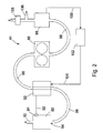
- FIG. 2 shows a detailed schematic representation of a preferred turbine module 44, as in an Appendix 1, as in FIG. 1 reproduced, can be used.
- the turbine module 44 includes a combustor 80 into which a compressed air / gas mixture may be fed via the line 82 from the gas compressor 42 (not shown) and, for example, a separate air compressor (not shown).
- the combustion chamber 80 the air / gas mixture is ignited.
- the combustion chamber 80 is preferably designed to withstand temperatures up to 3000 °.
- the expanding combustion exhaust gas is supplied via the outlet 84 of the combustor 80 and the conduit 86 of the turbine 88, which may be, for example, a positive-displacement rotary turbine.
- the heat energy present in the combustion exhaust gas is used via the heat exchanger 90 to convert water into water vapor, which then passes via the supply line 92 and the system for feeding steam 94 into the combustion chamber 80.
- the combustion exhaust gases leaving the turbine 88 via the line 96 are freed of water residues in the condenser 98.
- the in the capacitor 98 accumulating amounts of water can be supplied via a line 100 to a water treatment plant 102, which in turn can serve in a preferred embodiment as a reservoir for the supply of water via the line 104 into the heat exchanger 90.
- the turbine module 44 may also be provided with a drain 106 through which the combustion exhaust gases may be at least partially supplied to the burners of the gasifier furnace.
- the combustion gas passing through the condenser 98 may be supplied to an exhaust gas purification unit 108.
- FIG. 3 1 shows a waste utilization plant module 70 according to the invention comprising a total of nine waste recycling plants or plant lines 1 according to the invention.
- Each plant or plant line 1 is equipped with a gasification furnace, for example a cupola 10, a falling stream device and / or a quench 32, a fan unit 40, a gas purification plant 38, a gas - Or air / gas compressor 42, a turbine module 44 and a generator 58 equipped.
- a gasification furnace for example a cupola 10, a falling stream device and / or a quench 32
- a fan unit 40 for example a fan unit 40, a gas purification plant 38, a gas - Or air / gas compressor 42, a turbine module 44 and a generator 58 equipped.
- the plants or plant lines 1 in the FIG. 3 shown shown only schematically and may, for example, have all the details, as they correspond to the embodiment according to FIG. 1 are described.
- three plants or plant lines 1 can be supplied via a storage bunker 4
- This waste is fed via suitable crane devices or other suitable feed devices to the carburetor or cupola furnaces 10 (not shown).
- the storage bin 4 are filled via the Brikettiertician 2 each with briquetted waste material.
- a plant or a plant line is not equipped with a separate generator 58, but that two or more plants or system lines deliver the generated torque to a single generator 58 (not shown).
- An advantage of the system module 70 according to the invention is that individual systems or system lines 1 can be connected to one another via suitable bypass lines.
- a bypass line 72 may be provided from the carburetor furnace 10 of the first plant line to the falling line device 32 of the second plant line be.
- bypass line may be provided from the gasifier furnace of the second plant line to the falling stream device of the first plant line. Conveniently, these lines are accomplished via a common bypass line equipped with suitable valves.
- the bypass conduits 72 may also be attached to the connecting conduits between the gasifier furnace 10 and the downcomer 32 of a plant 1, as in FIG FIG. 3 outlined.
- Further bypass lines 74 can be provided, for example, between the falling-stream device 32 of a first line of equipment and the fan unit 40 of a second line of equipment.
- bypass lines 76, 78 and 79 may be present, between the fan 40 of a first line and the gas cleaning system 38 a second line, the gas cleaning system of a first line and the gas compressor a second line or the gas compressor a first line and system Turbine module of a second plant line.
- bypass lines are in the in FIG. 3 reproduced schematic overview of a system module 72 according to the invention has not been drawn for all system lines, there may nevertheless be provided in the same way.
Landscapes
- Engineering & Computer Science (AREA)
- Chemical & Material Sciences (AREA)
- Combustion & Propulsion (AREA)
- Mechanical Engineering (AREA)
- Oil, Petroleum & Natural Gas (AREA)
- Organic Chemistry (AREA)
- General Engineering & Computer Science (AREA)
- Processing Of Solid Wastes (AREA)
Applications Claiming Priority (1)
| Application Number | Priority Date | Filing Date | Title |
|---|---|---|---|
| DE200810010919 DE102008010919A1 (de) | 2008-02-25 | 2008-02-25 | Abfallverwertungsanlage zur Erzeugung von Energie |
Publications (2)
| Publication Number | Publication Date |
|---|---|
| EP2110520A2 true EP2110520A2 (fr) | 2009-10-21 |
| EP2110520A3 EP2110520A3 (fr) | 2012-12-05 |
Family
ID=40589693
Family Applications (1)
| Application Number | Title | Priority Date | Filing Date |
|---|---|---|---|
| EP09002308A Withdrawn EP2110520A3 (fr) | 2008-02-25 | 2009-02-24 | Installation de traitement des déchets pour la production d'énergie |
Country Status (2)
| Country | Link |
|---|---|
| EP (1) | EP2110520A3 (fr) |
| DE (1) | DE102008010919A1 (fr) |
Citations (13)
| Publication number | Priority date | Publication date | Assignee | Title |
|---|---|---|---|---|
| US3729298A (en) | 1971-07-09 | 1973-04-24 | Union Carbide Corp | Solid refuse disposal process and apparatus |
| US3817724A (en) | 1972-05-11 | 1974-06-18 | Chevron Res | Gasification of solid carbonaceous waste material |
| DE3124865A1 (de) | 1980-06-25 | 1982-02-25 | Gi-dong Taegu GyungsanBuk Park | Kuppelofen |
| DE3149040A1 (de) | 1980-12-15 | 1982-10-21 | Kurherr Motoren AG, 6340 Baar | Verdraengerturbine |
| DE3121206C2 (de) | 1980-05-29 | 1986-09-11 | Union Carbide Corp., New York, N.Y. | Verfahren zum Vergasen fester Abfälle |
| EP0432287A1 (fr) | 1989-11-28 | 1991-06-19 | Waldemar H. Kurherr | Moteur rotatif |
| DE4200341A1 (de) | 1991-11-18 | 1993-05-19 | Kloeckner Humboldt Deutz Ag | Verfahren und vorrichtung zur hochtemperaturvergasung feinkoerniger brennwertreicher organischer abfallstoffe |
| DE69002082T2 (de) | 1989-04-27 | 1994-01-27 | Westinghouse Electric Corp | Verfahren und Vorrichtung zur Behandlung von ausgegrabenen Deponiematerialien in einem plasmabeheizten Kupolofen. |
| DE19545679A1 (de) | 1995-12-07 | 1997-06-12 | Haunold Werner | Mischnebelerzeugung zur Absorption von Geruchstoffen |
| DE19606575C2 (de) | 1996-02-22 | 1998-02-12 | Noell Krc Energie & Umwelt | Verfahren zur gleichzeitigen stofflichen und energetischen Verwertung von Rest- und Abfallstoffen in einem Hoch- oder Kupolofen |
| WO1999060320A2 (fr) | 1998-03-30 | 1999-11-25 | Hans Ulrich Feustel | Cubilot a circulation de gaz chauffe au coke pour la valorisation materielle et/ou energetique de materiaux de dechets de differentes compositions |
| EP0972556A1 (fr) | 1998-07-14 | 2000-01-19 | Climarotec Gesellschaft für raumklimatische Spezialanlagen mbH | Adsorption des composés gazeux hydrophobes et/ou aérosols d'un courant gazeux |
| DE19853717C2 (de) | 1998-11-20 | 2000-12-21 | Krc Umwelttechnik Gmbh | Verfahren und Vorrichtungen zur Vergasung kompaktierter organischer Materialien |
Family Cites Families (6)
| Publication number | Priority date | Publication date | Assignee | Title |
|---|---|---|---|---|
| DE843629C (de) * | 1944-07-10 | 1952-07-10 | Brown Ag | Verwendung der Verbrennung oder Vergasung von Muell zum Betrieb von Gasturbinenanlagen |
| US4170550A (en) * | 1978-03-30 | 1979-10-09 | Koppers Company, Inc. | Process for reducing aqueous effluents containing environmentally unacceptable compounds from a process for gasifying carbonaceous materials |
| DE4342165C1 (de) * | 1993-12-10 | 1995-05-11 | Umwelt & Energietech | Verfahren zur energetischen Nutzung von Biomasse |
| DE9411173U1 (de) * | 1994-07-09 | 1994-10-20 | Feustel, Hans Ulrich, Dipl.-Ing., 04277 Leipzig | Anlage für einen Kreislaufgas-Kupolofen zur energetischen und/oder wärmetechnischen Verwertung des Gichtgases |
| DE19608093C2 (de) * | 1996-03-02 | 2000-08-10 | Krc Umwelttechnik Gmbh | Verfahren zur Verwertung von Rest- und Abfallstoffen sowie heizwertarmen Brennstoffen in einem Zementofen |
| DE102006056480B4 (de) * | 2006-11-28 | 2008-09-04 | Berthold, Hermann | Verfahren und Anlage zur Nutzenergiegewinnung durch Müllvergasung |
-
2008
- 2008-02-25 DE DE200810010919 patent/DE102008010919A1/de not_active Withdrawn
-
2009
- 2009-02-24 EP EP09002308A patent/EP2110520A3/fr not_active Withdrawn
Patent Citations (13)
| Publication number | Priority date | Publication date | Assignee | Title |
|---|---|---|---|---|
| US3729298A (en) | 1971-07-09 | 1973-04-24 | Union Carbide Corp | Solid refuse disposal process and apparatus |
| US3817724A (en) | 1972-05-11 | 1974-06-18 | Chevron Res | Gasification of solid carbonaceous waste material |
| DE3121206C2 (de) | 1980-05-29 | 1986-09-11 | Union Carbide Corp., New York, N.Y. | Verfahren zum Vergasen fester Abfälle |
| DE3124865A1 (de) | 1980-06-25 | 1982-02-25 | Gi-dong Taegu GyungsanBuk Park | Kuppelofen |
| DE3149040A1 (de) | 1980-12-15 | 1982-10-21 | Kurherr Motoren AG, 6340 Baar | Verdraengerturbine |
| DE69002082T2 (de) | 1989-04-27 | 1994-01-27 | Westinghouse Electric Corp | Verfahren und Vorrichtung zur Behandlung von ausgegrabenen Deponiematerialien in einem plasmabeheizten Kupolofen. |
| EP0432287A1 (fr) | 1989-11-28 | 1991-06-19 | Waldemar H. Kurherr | Moteur rotatif |
| DE4200341A1 (de) | 1991-11-18 | 1993-05-19 | Kloeckner Humboldt Deutz Ag | Verfahren und vorrichtung zur hochtemperaturvergasung feinkoerniger brennwertreicher organischer abfallstoffe |
| DE19545679A1 (de) | 1995-12-07 | 1997-06-12 | Haunold Werner | Mischnebelerzeugung zur Absorption von Geruchstoffen |
| DE19606575C2 (de) | 1996-02-22 | 1998-02-12 | Noell Krc Energie & Umwelt | Verfahren zur gleichzeitigen stofflichen und energetischen Verwertung von Rest- und Abfallstoffen in einem Hoch- oder Kupolofen |
| WO1999060320A2 (fr) | 1998-03-30 | 1999-11-25 | Hans Ulrich Feustel | Cubilot a circulation de gaz chauffe au coke pour la valorisation materielle et/ou energetique de materiaux de dechets de differentes compositions |
| EP0972556A1 (fr) | 1998-07-14 | 2000-01-19 | Climarotec Gesellschaft für raumklimatische Spezialanlagen mbH | Adsorption des composés gazeux hydrophobes et/ou aérosols d'un courant gazeux |
| DE19853717C2 (de) | 1998-11-20 | 2000-12-21 | Krc Umwelttechnik Gmbh | Verfahren und Vorrichtungen zur Vergasung kompaktierter organischer Materialien |
Also Published As
| Publication number | Publication date |
|---|---|
| DE102008010919A1 (de) | 2009-09-03 |
| EP2110520A3 (fr) | 2012-12-05 |
Similar Documents
| Publication | Publication Date | Title |
|---|---|---|
| CH615215A5 (fr) | ||
| DE60015740T2 (de) | Biomassenverbrennungskammer für eine gasturbine | |
| EP2082013B1 (fr) | Procédé pour préparer un produit gazeux riche en hydrogène | |
| DE102006056480B4 (de) | Verfahren und Anlage zur Nutzenergiegewinnung durch Müllvergasung | |
| DE112011100718T5 (de) | Kohlenstoff-Konversionssystem mit integrierten Verarbeitungszonen | |
| EP2501786A1 (fr) | Conversion thermochimique de matériaux carbonés, en particulier pour la production d'énergie sans émissions | |
| EP2261560A1 (fr) | Procédé de transformation de déchets organiques d'origine ménagère ou industrielle | |
| DE102010018197A1 (de) | Verfahren und Vorrichtung zur Vergasung von Biomasse | |
| DE202006009174U1 (de) | Vorrichtung zur Erzeugung von Brenngas aus einem festen Brennstoff | |
| EP2641958B1 (fr) | Gazéificateur de biomasse | |
| EP1187891B1 (fr) | Procede et dispositif d'elimination de dechets | |
| EP1377649B1 (fr) | Installation et procede pour produire de l'energie par pyrolyse | |
| DE102004008621A1 (de) | Herdofenreaktoren und Verfahren zur Umwandlung fester und pastöser, organischer Stoffe in Prozessgas | |
| DD285819A5 (de) | Verfahren und eine maschine fuer die umsetzung von brennbaren schmutzstoffen oder abfaellen in saubere energie und brauchbare produkte | |
| DE102007017859A1 (de) | Vergaser | |
| EP1230322A1 (fr) | Proc d de mise en marche et d'arr t d'un dispositif servant l' limination et la r utilisation de d chets | |
| DE102009014410A1 (de) | Abfallverwertungsanlage zur Erzeugung von Energie | |
| EP3214155B1 (fr) | Procédé pour la production de gaz de synthèse pour la combustion dans un moteur à combustion interne. | |
| DE3439600C2 (fr) | ||
| DE69002446T2 (de) | Vorrichtung zum Vergasen fester Brennstoffe. | |
| EP2110520A2 (fr) | Installation de traitement des déchets pour la production d'énergie | |
| DE69204948T2 (de) | Methode und Vorrichtung zum Vergasen von festen Brennstoffen, enthaltend schmelzbare nicht-brennbare Materien. | |
| DE102006061583A1 (de) | Energiewandlungssystem für feste Biomasse und andere energetische, vergasbare Stoffe | |
| EP2148135B1 (fr) | Procédé et dispositif destinés au traitement thermique de déchets | |
| DE19843613C2 (de) | Verfahren und Vorrichtung zur Aufarbeitung von Abprodukten und Abfallstoffen |
Legal Events
| Date | Code | Title | Description |
|---|---|---|---|
| PUAI | Public reference made under article 153(3) epc to a published international application that has entered the european phase |
Free format text: ORIGINAL CODE: 0009012 |
|
| AK | Designated contracting states |
Kind code of ref document: A2 Designated state(s): AT BE BG CH CY CZ DE DK EE ES FI FR GB GR HR HU IE IS IT LI LT LU LV MC MK MT NL NO PL PT RO SE SI SK TR |
|
| AX | Request for extension of the european patent |
Extension state: AL BA RS |
|
| RIC1 | Information provided on ipc code assigned before grant |
Ipc: F01K 23/06 20060101AFI20120712BHEP Ipc: F02C 3/28 20060101ALI20120712BHEP |
|
| PUAL | Search report despatched |
Free format text: ORIGINAL CODE: 0009013 |
|
| AK | Designated contracting states |
Kind code of ref document: A3 Designated state(s): AT BE BG CH CY CZ DE DK EE ES FI FR GB GR HR HU IE IS IT LI LT LU LV MC MK MT NL NO PL PT RO SE SI SK TR |
|
| AX | Request for extension of the european patent |
Extension state: AL BA RS |
|
| RIC1 | Information provided on ipc code assigned before grant |
Ipc: F01K 23/06 20060101AFI20121029BHEP Ipc: F02C 3/28 20060101ALI20121029BHEP |
|
| STAA | Information on the status of an ep patent application or granted ep patent |
Free format text: STATUS: THE APPLICATION HAS BEEN WITHDRAWN |
|
| 18W | Application withdrawn |
Effective date: 20130612 |
|
| AKY | No designation fees paid |