EP2110486A2 - Anchor point for a lift assembly - Google Patents
Anchor point for a lift assembly Download PDFInfo
- Publication number
- EP2110486A2 EP2110486A2 EP09005209A EP09005209A EP2110486A2 EP 2110486 A2 EP2110486 A2 EP 2110486A2 EP 09005209 A EP09005209 A EP 09005209A EP 09005209 A EP09005209 A EP 09005209A EP 2110486 A2 EP2110486 A2 EP 2110486A2
- Authority
- EP
- European Patent Office
- Prior art keywords
- recess
- recess body
- section
- concrete
- rod
- Prior art date
- Legal status (The legal status is an assumption and is not a legal conclusion. Google has not performed a legal analysis and makes no representation as to the accuracy of the status listed.)
- Granted
Links
- 238000004873 anchoring Methods 0.000 claims abstract description 23
- 239000002184 metal Substances 0.000 claims abstract description 22
- 238000009415 formwork Methods 0.000 claims description 11
- 239000006260 foam Substances 0.000 claims description 3
- 238000007790 scraping Methods 0.000 claims description 2
- 239000011796 hollow space material Substances 0.000 abstract 2
- 238000000465 moulding Methods 0.000 abstract 1
- 238000006073 displacement reaction Methods 0.000 description 3
- 238000004519 manufacturing process Methods 0.000 description 2
- 238000010276 construction Methods 0.000 description 1
- 239000013589 supplement Substances 0.000 description 1
Images

Classifications
-
- E—FIXED CONSTRUCTIONS
- E04—BUILDING
- E04B—GENERAL BUILDING CONSTRUCTIONS; WALLS, e.g. PARTITIONS; ROOFS; FLOORS; CEILINGS; INSULATION OR OTHER PROTECTION OF BUILDINGS
- E04B1/00—Constructions in general; Structures which are not restricted either to walls, e.g. partitions, or floors or ceilings or roofs
- E04B1/38—Connections for building structures in general
- E04B1/41—Connecting devices specially adapted for embedding in concrete or masonry
- E04B1/4114—Elements with sockets
- E04B1/4142—Elements with sockets with transverse hook- or loop-receiving parts
-
- B—PERFORMING OPERATIONS; TRANSPORTING
- B66—HOISTING; LIFTING; HAULING
- B66B—ELEVATORS; ESCALATORS OR MOVING WALKWAYS
- B66B11/00—Main component parts of lifts in, or associated with, buildings or other structures
- B66B11/0005—Constructional features of hoistways
-
- B—PERFORMING OPERATIONS; TRANSPORTING
- B66—HOISTING; LIFTING; HAULING
- B66B—ELEVATORS; ESCALATORS OR MOVING WALKWAYS
- B66B7/00—Other common features of elevators
- B66B7/06—Arrangements of ropes or cables
- B66B7/08—Arrangements of ropes or cables for connection to the cars or cages, e.g. couplings
-
- E—FIXED CONSTRUCTIONS
- E04—BUILDING
- E04G—SCAFFOLDING; FORMS; SHUTTERING; BUILDING IMPLEMENTS OR AIDS, OR THEIR USE; HANDLING BUILDING MATERIALS ON THE SITE; REPAIRING, BREAKING-UP OR OTHER WORK ON EXISTING BUILDINGS
- E04G15/00—Forms or shutterings for making openings, cavities, slits, or channels
- E04G15/04—Cores for anchor holes or the like around anchors embedded in the concrete
-
- E—FIXED CONSTRUCTIONS
- E04—BUILDING
- E04B—GENERAL BUILDING CONSTRUCTIONS; WALLS, e.g. PARTITIONS; ROOFS; FLOORS; CEILINGS; INSULATION OR OTHER PROTECTION OF BUILDINGS
- E04B1/00—Constructions in general; Structures which are not restricted either to walls, e.g. partitions, or floors or ceilings or roofs
- E04B1/38—Connections for building structures in general
- E04B1/41—Connecting devices specially adapted for embedding in concrete or masonry
- E04B2001/4192—Connecting devices specially adapted for embedding in concrete or masonry attached to concrete reinforcing elements, e.g. rods or wires
Abstract
Description
Aufzugsmontageanker mit einem Anhängeabschnitt zum Anhängen von Schäkeln, Haken, Seilen oder dergleichen und mindestens einem Verankerungsabschnitt zum Eingiessen in eine Betondecke.Elevator assembly anchor with a trailer section for attaching shackles, hooks, ropes or the like and at least one anchoring section for pouring into a concrete pavement.
In Aufzug-Maschinenräumen oder im Schachtkopfbereich von Aufzugsschächten müssen zum Anhängen von Montageplattformen zur Montage oder Wartung des Aufzuges in der Decke des Schachtes Lastanker angebracht werden, welche Lasten von mehreren Tonnen halten können. Für diese Anwendung sind lastgeprüfte Aufzugsmontageanker bekannt. Ein Beispiel für einen solchen Aufzugsmontageanker ist eine vormontierte Kombination aus einem Wellenanker (Verankerungsabschnitt) und einer Seilöse (Anhängeabschnitt). Der Wellenanker wird in die Decke des Aufzugsschachtes einbetoniert und das Anhängen von Schäkeln, Haken, Seilen oder dergleichen geschieht über die Seilöse im Schachtkopfbereich. Um Tragfähigkeiten von bis zu 4 Tonnen zu erreichen, muss ein solcher Wellenanker eine Länge von etwa 30 cm aufweisen. Die Seilöse ragt gemäss einem solchen Aufzugsmontageanker bis zu 25 cm in den Schachtkopfbereich hinein. Eine solche Konstruktion braucht eine Deckenstärke von mindestens 30 cm. Für geringere Deckenstärken, bei denen nicht beliebig viel Platz für die Verankerung vorhanden ist, sind auch kleinere Varianten bekannt. Solche kleinere Varianten sind aber nur für geringere Lasten geprüft und zugelassen.In elevator machinery rooms or in the shaft head area of elevator shafts, load anchors must be mounted in the ceiling of the shaft for attaching mounting platforms for mounting or maintaining the elevator, which can hold loads of several tons. Load-tested lift mounting anchors are known for this application. An example of such a lift mounting anchor is a preassembled combination of a shaft anchor (anchoring section) and a cable eye (attachment section). The wave anchor is concreted in the ceiling of the elevator shaft and the attachment of shackles, hooks, ropes or the like is done via the cable eye in the shaft head area. In order to achieve load capacities of up to 4 tons, such a wave anchor must have a length of about 30 cm. The cable eye protrudes up to 25 cm into the shaft head area according to such an elevator assembly anchor. Such a construction needs a ceiling thickness of at least 30 cm. For smaller ceilings, where there is not an arbitrary amount of space for anchoring, even smaller variants are known. Such smaller variants are tested and approved only for lower loads.
Gegenstand der Erfindung ist es, eine Vorrichtung der eingangs genannten Art anzugeben, bei der der Anhängeabschnitt nicht den für den Aufzug verwendbaren Platz beansprucht und die dennoch eine Tragfähigkeit für Lasten von mehreren Tonnen aufweist.The invention is to provide a device of the type mentioned, in which the appendage section does not claim the usable space for the elevator and yet has a capacity for loads of several tons.
Erfindungsgemäss wird dies bei einer solchen Vorrichtung dadurch erreicht, dass der Anhängeabschnitt in einem Aussparungskörper angeordnet ist, der ebenfalls zum Eingiessen in die Betondecke angrenzend an deren untere Schalung vorgesehen ist und der in der Betondecke nach dem Entschalen einen den Anhängeabschnitt umgebenden Hohlraum angrenzend an die Unterseite der Decke erzeugt.According to the invention, this is achieved in such a device in that the attachment portion is arranged in a recess body which is also provided for pouring into the concrete floor adjacent to the lower formwork and which in the concrete ceiling after demoulding a cavity surrounding the attachment portion adjacent to the underside the ceiling generated.
Die Erfindung hat demnach den Vorteil, dass der Aufzugsmontageanker nicht in den Schachtkopfbereich vorstösst und dabei den Platz beansprucht, welcher sonst für den Aufzug verwendet werden kann.The invention therefore has the advantage that the elevator assembly anchor does not project into the shaft head area and thereby takes up the space which can otherwise be used for the elevator.
Gemäss einer ersten bevorzugten Ausführungsform ist der erfindungsgemässe Aussparungskörper länglich ausgebildet und weist eine Länge von 12 - 25 cm, vorzugsweise 15 - 20 cm, eine Breite von 5 - 10 cm, vorzugsweise 6 - 8 cm, und eine Höhe von 4 - 10 cm, vorzugsweise 5 - 7 cm, auf. Eine längliche Form des Aussparungskörper erleichtert das Anhängen von Schäkeln, Haken, Seilen oder dergleichen. Der Aussparungskörper kann aus formstabilem Schaumstoff oder dergleichen bestehen, welcher nach der Montage durch zB. Auskratzten entfernt werden kann. Der Aussparungskörper kann auch schalenförmig mit einer Wandung aus Blech oder Kunststoff ausgebildet sein. Weiter kann der Aussparungskörper mit Mitteln zum Annageln auf der Schalung der Betondecke versehen sein.According to a first preferred embodiment, the recess body according to the invention is elongated and has a length of 12 to 25 cm, preferably 15 to 20 cm, a width of 5 to 10 cm, preferably 6 to 8 cm, and a height of 4 to 10 cm. preferably 5 - 7 cm, on. An elongate shape of the recess body facilitates the attachment of shackles, hooks, ropes or the like. The recess body may consist of dimensionally stable foam or the like, which after assembly by eg. Scraping can be removed. The recess body may also be formed shell-shaped with a wall of sheet metal or plastic. Further, the recess body may be provided with means for nailing on the formwork of the concrete ceiling.
Gemäss einer ersten bevorzugten Ausführungsform wird der Anhängeabschnitt durch einen Stab gebildet, weicher an zwei Stellen durch die Wandung des erfindungsgemässen Aussparungskörpers in den umgebenden Beton hineinreicht und dabei zwei Verankerungsabschnitte bildet. Der Stab kann vorzugsweise im Bereich des Anhängeabschnitts nach unten gebogen sein, um ein Anhängen von Schäkeln, Haken, Seilen oder dergleichen zu erleichtern. Um einen höheren Ausbruchwiderstand des Aufzugsmontageankers im Beton zu erreichen, kann der Stab im Bereich wenigstens eines Verankerungsabschnittes hochgezogen sein. Eine solche bevorzugte Ausführungsform hat den Vorteil, dass Anhänge- und Verankerungsabschnitt aus einem Stab gebildet werden. Eine solche erfindungsgemässe Vorrichtung ist leicht herzustellen und kann fest mit dem Aussparungskörper verbunden werden, um eine Montage auf der Schalung zu erleichtern.According to a first preferred embodiment, the attachment section is formed by a rod, which extends at two points through the wall of the recess body according to the invention into the surrounding concrete and thereby forms two anchoring sections. The rod may preferably be bent downwardly in the region of the attachment portion to facilitate attachment of shackles, hooks, ropes or the like. In order to achieve a higher breakout resistance of the lift mounting anchor in the concrete, the rod can in the area at least be pulled up an anchorage section. Such a preferred embodiment has the advantage that the attachment and anchoring sections are formed from a rod. Such an inventive device is easy to manufacture and can be firmly connected to the recess body to facilitate mounting on the formwork.
Gemäss einer zweiten Ausführungsform umfasst der Verankerungsabschnitt eine über dem Aussparungskörper liegende Metallplatte, welche durch die Wandung des Aussparungskörpers hindurch mit dem Anhängeabschnitt verbunden ist. Der Anhängeabschnitt kann die Form einer Öse oder Schlaufe aufweisen und kommt in der oben beschriebenen Aussparung zu liegen. Zur Lastverteilung kann die Metallplatte auf mindestens einer Seite über den Bereich der Aussparung hinausreichen. Zur weiteren Lastverteilung kann mindestens ein Stab an der Metallplatte befestigt sein. Dieser Stab reicht, vorzugsweise auf beiden Seiten, 25 - 50 cm über die Metallplatte hinaus.According to a second embodiment, the anchoring portion comprises a metal plate lying above the recess body, which is connected to the attachment portion through the wall of the recess body. The appendage portion may be in the form of an eyelet or loop and come to lie in the recess described above. For load distribution, the metal plate may extend beyond the region of the recess on at least one side. For further load distribution, at least one rod may be attached to the metal plate. This bar extends, preferably on both sides, 25 - 50 cm beyond the metal plate.
Gemäss einer dritten Ausführungsform umfasst der Verankerungsabschnitt einen Wellenanker, der sich im Beton über dem Aussparungskörper befindet und welcher durch die Wandung des Aussparungskörpers hindurch mit dem Anhängeabschnitt verbunden ist. Der Anhängeabschnitt kann die Form einer Öse oder Schlaufe aufweisen und kommt in der oben beschriebenen Aussparung zu liegen.According to a third embodiment, the anchoring portion comprises a wave anchor which is located in the concrete above the recess body and which is connected through the wall of the recess body with the appendage portion. The appendage portion may be in the form of an eyelet or loop and come to lie in the recess described above.
Vorzugsweise kann der Anhängeabschnitt in allen Ausführungsformen asymmetrisch zur Längsachse der Aussparung angebracht sein, um ein Anhängen von Schäkeln, Haken, Seilen oder dergleichen zu erleichtern.Preferably, in all embodiments, the attachment portion may be mounted asymmetrically to the longitudinal axis of the recess to facilitate attachment of shackles, hooks, ropes, or the like.
Die Erfindung soll nachfolgend anhand von Ausführungsbeispielen im Zusammenhang mit der Zeichnung näher erläutert werden. Es zeigen:
- Fig. 1
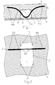
- eine erste Ausführungsform einer erfindungsgemässen Vorrichtung mit einem Stab als Anhänge- und Verankerungsabschnitt in einer Schnittdarstellung von der Seite gesehen;
- Fig. 2
- die Ausführungsform von
Fig. 1 in einer Aufsicht; - Fig. 3
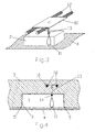
- eine zweite Ausführungsform einer erfindungsgemässen Vorrichtung in perspektivischer Darstellung mit einer Metallplatte als Verankerunsabschnitt;
- Fig. 4
- eine Schnittdarstellung der Vorrichtung von
Fig. 3 von der Seite gesehen; - Fig. 5
- eine Aufsicht der Vorrichtung von
Fig. 3 ; - Fig. 6
- eine dritte Ausführungsform einer erfindungsgemässen Vorrichtung in einer Schnittdarstellung von der Seite gesehen.
- Fig. 1
- a first embodiment of an inventive device with a rod as attachment and anchoring section in a sectional view seen from the side;
- Fig. 2
- the embodiment of
Fig. 1 in a supervision; - Fig. 3
- a second embodiment of an inventive device in perspective view with a metal plate as Verankerunsabschnitt;
- Fig. 4
- a sectional view of the device of
Fig. 3 seen from the side; - Fig. 5
- a plan view of the device of
Fig. 3 ; - Fig. 6
- a third embodiment of an inventive device seen in a sectional view from the side.
Die Vorrichtung in
Die Ausführungsform von
Die vorbeschriebene erste Ausführungsform hat den Vorteil, dass Anhänge- und Verankerungsabschnitt 6a, 6b durch ein und denselben Stab 6 gebildet werden, was die Herstellung des Aufzugsmontageankers vereinfacht. Die Verankerungsabschnitte 6b können beliebig weit in die Betondecke 3 hineinragen. Somit kann ein sehr hoher Ausbruchwiderstand erreicht werden, was das Tragen von Lasten von mehreren Tonnen ermöglicht. Da die Verankerung waagrecht und nicht senkrecht, wie bei herkömmlichen Aufzugsmontageankem, in die Decke hineingeführt wird, kann diese Ausführungsform auch in Betondecken von geringerer Stärke verwendet werden und trotzdem Lasten von mehreren Tonnen tragen.The above-described first embodiment has the advantage that attachment and anchoring
Die Vorrichtung in
Auch in der zweiten Ausführungsform kommt der Anhängeabschnitt 11 in der Aussparung 1 zu liegen und ist somit in die Betondecke 3 hineinversetzt. Dadurch ragt kein Teil des Aufzugsmontageankers in den Schachtkopfbereich und der gesamte Schachtkopfbereich kann für den Aufzug verwendet werden. Durch die Metallplatte 10 und den Stab 12 können Tragfähigkeiten von mehreren Tonnen erreicht werden. Weiter können die Dimensionen der Vorrichtung so gewählt werden, dass sie auch in Betondecken von geringer Stärke eingegossen werden kann.Also in the second embodiment, the
Die Vorrichtung in
- 11
- Aussparungrecess
- 22
- Aussparungskörperrecess former
- 33
- Betondeckeconcrete ceiling
- 44
- Schalungformwork
- 55
- Mittel zum AnnagelnMeans for nailing
- 66
- StabRod
- 6a6a
- AnhängeabschnittSupplements section
- 6b6b
- Verankerungsabschnittanchoring section
- 1010
- Metallplattemetal plate
- 1111
- Verankerungsabschnittanchoring section
- 1212
- StabRod
- 1313
- StabRod
- 1414
- Klemm- oder SchraubhülseClamp or screw sleeve
- 2020
- WellenankerWaved anchor
Claims (15)
Applications Claiming Priority (1)
| Application Number | Priority Date | Filing Date | Title |
|---|---|---|---|
| CH00591/08A CH718496B1 (en) | 2008-04-16 | 2008-04-16 | elevator mounting anchor. |
Publications (3)
| Publication Number | Publication Date |
|---|---|
| EP2110486A2 true EP2110486A2 (en) | 2009-10-21 |
| EP2110486A3 EP2110486A3 (en) | 2012-10-03 |
| EP2110486B1 EP2110486B1 (en) | 2020-03-25 |
Family
ID=40790837
Family Applications (1)
| Application Number | Title | Priority Date | Filing Date |
|---|---|---|---|
| EP09005209.3A Active EP2110486B1 (en) | 2008-04-16 | 2009-04-09 | Anchor point for a lift assembly |
Country Status (2)
| Country | Link |
|---|---|
| EP (1) | EP2110486B1 (en) |
| CH (1) | CH718496B1 (en) |
Cited By (5)
| Publication number | Priority date | Publication date | Assignee | Title |
|---|---|---|---|---|
| DE202010010127U1 (en) | 2010-07-12 | 2011-10-24 | Pfeifer Seil- Und Hebetechnik Gmbh | Deposit box and use of a deposit box |
| WO2013064497A1 (en) | 2011-10-31 | 2013-05-10 | Inventio Ag | Load loop box and anchor device |
| EP2913458A1 (en) * | 2014-02-28 | 2015-09-02 | Lesage Developpement S.A.S. | Wall with integrated formwork comprising a secured opening, device for forming such an opening and method for manufacturing such a wall with integrated formwork |
| CN106049883A (en) * | 2016-05-23 | 2016-10-26 | 中交第航务工程局有限公司 | Novel lifting point construction process for concrete components |
| DE102016118883A1 (en) * | 2016-10-05 | 2018-04-05 | Georg Weidner | Weldable concrete loop |
Families Citing this family (1)
| Publication number | Priority date | Publication date | Assignee | Title |
|---|---|---|---|---|
| CN105350492B8 (en) * | 2014-11-10 | 2017-05-31 | 郭二旺 | The manufacture method of brace type deformed concrete crack sealing swaging die |
Citations (4)
| Publication number | Priority date | Publication date | Assignee | Title |
|---|---|---|---|---|
| FR2167274A5 (en) * | 1972-01-11 | 1973-08-24 | Arteon Marcel | Cast panels contg inserts -eg anchorage bolts temporarily - located during casting between split plastic (gps) shells |
| DE3248604A1 (en) * | 1982-12-30 | 1984-07-12 | Gebr. Seifert GmbH & Co, 5880 Lüdenscheid | Device for suspending concrete building elements or the like from the load hooks of cranes or the like |
| DE3633633A1 (en) * | 1986-10-03 | 1988-06-16 | Modersohn Gmbh & Co Kg Wilh | Attachment point for fastening a fall-preventing means |
| DE29722108U1 (en) * | 1997-12-16 | 1999-04-15 | Pfeifer Seil Hebetech | Precast concrete and transport anchor for the transport of this precast concrete |
-
2008
- 2008-04-16 CH CH00591/08A patent/CH718496B1/en unknown
-
2009
- 2009-04-09 EP EP09005209.3A patent/EP2110486B1/en active Active
Patent Citations (4)
| Publication number | Priority date | Publication date | Assignee | Title |
|---|---|---|---|---|
| FR2167274A5 (en) * | 1972-01-11 | 1973-08-24 | Arteon Marcel | Cast panels contg inserts -eg anchorage bolts temporarily - located during casting between split plastic (gps) shells |
| DE3248604A1 (en) * | 1982-12-30 | 1984-07-12 | Gebr. Seifert GmbH & Co, 5880 Lüdenscheid | Device for suspending concrete building elements or the like from the load hooks of cranes or the like |
| DE3633633A1 (en) * | 1986-10-03 | 1988-06-16 | Modersohn Gmbh & Co Kg Wilh | Attachment point for fastening a fall-preventing means |
| DE29722108U1 (en) * | 1997-12-16 | 1999-04-15 | Pfeifer Seil Hebetech | Precast concrete and transport anchor for the transport of this precast concrete |
Cited By (8)
| Publication number | Priority date | Publication date | Assignee | Title |
|---|---|---|---|---|
| DE202010010127U1 (en) | 2010-07-12 | 2011-10-24 | Pfeifer Seil- Und Hebetechnik Gmbh | Deposit box and use of a deposit box |
| EP2407612A2 (en) | 2010-07-12 | 2012-01-18 | Pfeifer Seil- und Hebetechnik GmbH | Rebar box and use of a rebar box |
| EP2407612A3 (en) * | 2010-07-12 | 2013-12-11 | Pfeifer Holding GmbH & Co. KG | Rebar box and use of a rebar box |
| WO2013064497A1 (en) | 2011-10-31 | 2013-05-10 | Inventio Ag | Load loop box and anchor device |
| EP2913458A1 (en) * | 2014-02-28 | 2015-09-02 | Lesage Developpement S.A.S. | Wall with integrated formwork comprising a secured opening, device for forming such an opening and method for manufacturing such a wall with integrated formwork |
| FR3018087A1 (en) * | 2014-02-28 | 2015-09-04 | Lesage Dev | WALL COMPRISING A SECURE OPENING, DEVICE FOR FORMING SUCH AN OPENING AND METHOD OF MANUFACTURING SUCH A WALL |
| CN106049883A (en) * | 2016-05-23 | 2016-10-26 | 中交第航务工程局有限公司 | Novel lifting point construction process for concrete components |
| DE102016118883A1 (en) * | 2016-10-05 | 2018-04-05 | Georg Weidner | Weldable concrete loop |
Also Published As
| Publication number | Publication date |
|---|---|
| EP2110486A3 (en) | 2012-10-03 |
| EP2110486B1 (en) | 2020-03-25 |
| CH718496B1 (en) | 2022-10-14 |
Similar Documents
| Publication | Publication Date | Title |
|---|---|---|
| EP0418699B1 (en) | Sealing apparatus for concrete joints and procedure for its filling | |
| AT519067B1 (en) | DEHNFUGENSCHALUNG | |
| EP2110486A2 (en) | Anchor point for a lift assembly | |
| AT513576B1 (en) | Wall formwork system and a method for producing a wall section with a Isolierschalung | |
| DE2900759A1 (en) | DOUBLE FLOORING SYSTEM AND PRODUCTION METHOD | |
| WO2008092664A2 (en) | Construction element | |
| CH678204A5 (en) | ||
| DE202006000143U1 (en) | Foundation formwork has anchor plate(s) attached to base of U-profile transversely with respect to profile protrudes on both sides of profile and with at least one hole in both protruding parts engaged by yokes | |
| EP3892789B1 (en) | Formwork system | |
| EP2516761B1 (en) | Device for connecting two components separated by a gap and for absorbing transverse forces that occur between the components | |
| DE7714716U1 (en) | ANCHORS FOR CAPTURING THE DISTANCE TO THE STRUCTURAL WALL LEAVING COMPONENTS | |
| DE102020109531B3 (en) | Formwork system | |
| DE2325483A1 (en) | BASE PLATE MADE OF REINFORCED FACTORY CONCRETE FOR BALCONIES ETC. WITH THE RAILING ON | |
| DE102005028697B4 (en) | System for building a building wall | |
| EP3333350B1 (en) | Fitting for securing window and door frames to a soffit and process that uses such fittings | |
| CH715831A2 (en) | Connecting element for connecting a shuttering panel to another structural unit, shuttering unit with connecting element, connecting unit with connecting element, set of parts for building shuttering and shuttering to form a cast concrete element. | |
| EP3921490A1 (en) | Mounting system for mounting an anchoring device and method for mounting an anchoring device on a partial construction made of concrete | |
| DE841722C (en) | Mold for the production of building panels | |
| DE202017001504U1 (en) | Lightweight wall, in particular for the creation of a partition wall in rooms of buildings | |
| DE2923153C2 (en) | Holding device for support cheeks to support slope material on an embankment | |
| DE10028514C1 (en) | Shuttering unit for edge shuttering has shuttering element provided with openings receiving fixing bolts for securing to further shuttering unit | |
| CH696204A5 (en) | Apparatus for shear reinforcement. | |
| EP1387910A1 (en) | Connector element and method for connecting a prefabricated concrete piece with a section of a building | |
| DE102012007700B4 (en) | Reinforced concrete floor with at least one foot purlin attached | |
| AT508798A2 (en) | FORMWORK |
Legal Events
| Date | Code | Title | Description |
|---|---|---|---|
| PUAI | Public reference made under article 153(3) epc to a published international application that has entered the european phase |
Free format text: ORIGINAL CODE: 0009012 |
|
| AK | Designated contracting states |
Kind code of ref document: A2 Designated state(s): AT BE BG CH CY CZ DE DK EE ES FI FR GB GR HR HU IE IS IT LI LT LU LV MC MK MT NL NO PL PT RO SE SI SK TR |
|
| PUAL | Search report despatched |
Free format text: ORIGINAL CODE: 0009013 |
|
| AK | Designated contracting states |
Kind code of ref document: A3 Designated state(s): AT BE BG CH CY CZ DE DK EE ES FI FR GB GR HR HU IE IS IT LI LT LU LV MC MK MT NL NO PL PT RO SE SI SK TR |
|
| AX | Request for extension of the european patent |
Extension state: AL BA RS |
|
| RIC1 | Information provided on ipc code assigned before grant |
Ipc: E04G 21/14 20060101ALI20120829BHEP Ipc: B66C 1/66 20060101ALI20120829BHEP Ipc: E04B 1/41 20060101AFI20120829BHEP |
|
| 17P | Request for examination filed |
Effective date: 20130321 |
|
| STAA | Information on the status of an ep patent application or granted ep patent |
Free format text: STATUS: EXAMINATION IS IN PROGRESS |
|
| 17Q | First examination report despatched |
Effective date: 20170120 |
|
| GRAP | Despatch of communication of intention to grant a patent |
Free format text: ORIGINAL CODE: EPIDOSNIGR1 |
|
| STAA | Information on the status of an ep patent application or granted ep patent |
Free format text: STATUS: GRANT OF PATENT IS INTENDED |
|
| INTG | Intention to grant announced |
Effective date: 20190819 |
|
| GRAS | Grant fee paid |
Free format text: ORIGINAL CODE: EPIDOSNIGR3 |
|
| GRAJ | Information related to disapproval of communication of intention to grant by the applicant or resumption of examination proceedings by the epo deleted |
Free format text: ORIGINAL CODE: EPIDOSDIGR1 |
|
| GRAL | Information related to payment of fee for publishing/printing deleted |
Free format text: ORIGINAL CODE: EPIDOSDIGR3 |
|
| STAA | Information on the status of an ep patent application or granted ep patent |
Free format text: STATUS: EXAMINATION IS IN PROGRESS |
|
| INTC | Intention to grant announced (deleted) | ||
| GRAP | Despatch of communication of intention to grant a patent |
Free format text: ORIGINAL CODE: EPIDOSNIGR1 |
|
| STAA | Information on the status of an ep patent application or granted ep patent |
Free format text: STATUS: GRANT OF PATENT IS INTENDED |
|
| GRAA | (expected) grant |
Free format text: ORIGINAL CODE: 0009210 |
|
| STAA | Information on the status of an ep patent application or granted ep patent |
Free format text: STATUS: THE PATENT HAS BEEN GRANTED |
|
| INTG | Intention to grant announced |
Effective date: 20200129 |
|
| AK | Designated contracting states |
Kind code of ref document: B1 Designated state(s): AT BE BG CH CY CZ DE DK EE ES FI FR GB GR HR HU IE IS IT LI LT LU LV MC MK MT NL NO PL PT RO SE SI SK TR |
|
| REG | Reference to a national code |
Ref country code: GB Ref legal event code: FG4D Free format text: NOT ENGLISH |
|
| REG | Reference to a national code |
Ref country code: AT Ref legal event code: REF Ref document number: 1248715 Country of ref document: AT Kind code of ref document: T Effective date: 20200415 Ref country code: IE Ref legal event code: FG4D Free format text: LANGUAGE OF EP DOCUMENT: GERMAN |
|
| REG | Reference to a national code |
Ref country code: DE Ref legal event code: R096 Ref document number: 502009016140 Country of ref document: DE |
|
| REG | Reference to a national code |
Ref country code: CH Ref legal event code: NV Representative=s name: RENTSCH PARTNER AG, CH Ref country code: CH Ref legal event code: PFA Owner name: JORDAHL H-BAU AG, CH Free format text: FORMER OWNER: ANKABA ANKERTECHNIK UND BAUHANDEL AG, CH |
|
| REG | Reference to a national code |
Ref country code: DE Ref legal event code: R082 Ref document number: 502009016140 Country of ref document: DE Representative=s name: ZEUNER SUMMERER STUETZ PATENT- UND RECHTSANWAL, DE Ref country code: DE Ref legal event code: R081 Ref document number: 502009016140 Country of ref document: DE Owner name: JORDAHL H-BAU AG, CH Free format text: FORMER OWNER: ANKABA ANKERTECHNIK UND BAUHANDEL AG, BRUETTISELLEN, CH |
|
| REG | Reference to a national code |
Ref country code: LU Ref legal event code: HC Owner name: JORDAHL H-BAU AG; CH Free format text: FORMER OWNER: ANKABA ANKERTECHNIK UND BAUHANDEL AG Effective date: 20200624 |
|
| PG25 | Lapsed in a contracting state [announced via postgrant information from national office to epo] |
Ref country code: NO Free format text: LAPSE BECAUSE OF FAILURE TO SUBMIT A TRANSLATION OF THE DESCRIPTION OR TO PAY THE FEE WITHIN THE PRESCRIBED TIME-LIMIT Effective date: 20200625 Ref country code: FI Free format text: LAPSE BECAUSE OF FAILURE TO SUBMIT A TRANSLATION OF THE DESCRIPTION OR TO PAY THE FEE WITHIN THE PRESCRIBED TIME-LIMIT Effective date: 20200325 |
|
| PG25 | Lapsed in a contracting state [announced via postgrant information from national office to epo] |
Ref country code: BG Free format text: LAPSE BECAUSE OF FAILURE TO SUBMIT A TRANSLATION OF THE DESCRIPTION OR TO PAY THE FEE WITHIN THE PRESCRIBED TIME-LIMIT Effective date: 20200625 Ref country code: GR Free format text: LAPSE BECAUSE OF FAILURE TO SUBMIT A TRANSLATION OF THE DESCRIPTION OR TO PAY THE FEE WITHIN THE PRESCRIBED TIME-LIMIT Effective date: 20200626 Ref country code: LV Free format text: LAPSE BECAUSE OF FAILURE TO SUBMIT A TRANSLATION OF THE DESCRIPTION OR TO PAY THE FEE WITHIN THE PRESCRIBED TIME-LIMIT Effective date: 20200325 Ref country code: HR Free format text: LAPSE BECAUSE OF FAILURE TO SUBMIT A TRANSLATION OF THE DESCRIPTION OR TO PAY THE FEE WITHIN THE PRESCRIBED TIME-LIMIT Effective date: 20200325 Ref country code: SE Free format text: LAPSE BECAUSE OF FAILURE TO SUBMIT A TRANSLATION OF THE DESCRIPTION OR TO PAY THE FEE WITHIN THE PRESCRIBED TIME-LIMIT Effective date: 20200325 |
|
| REG | Reference to a national code |
Ref country code: NL Ref legal event code: MP Effective date: 20200325 |
|
| REG | Reference to a national code |
Ref country code: LT Ref legal event code: MG4D |
|
| PG25 | Lapsed in a contracting state [announced via postgrant information from national office to epo] |
Ref country code: NL Free format text: LAPSE BECAUSE OF FAILURE TO SUBMIT A TRANSLATION OF THE DESCRIPTION OR TO PAY THE FEE WITHIN THE PRESCRIBED TIME-LIMIT Effective date: 20200325 |
|
| REG | Reference to a national code |
Ref country code: AT Ref legal event code: HC Ref document number: 1248715 Country of ref document: AT Kind code of ref document: T Owner name: JORDAHL H-BAU AG, CH Effective date: 20200901 |
|
| PG25 | Lapsed in a contracting state [announced via postgrant information from national office to epo] |
Ref country code: LT Free format text: LAPSE BECAUSE OF FAILURE TO SUBMIT A TRANSLATION OF THE DESCRIPTION OR TO PAY THE FEE WITHIN THE PRESCRIBED TIME-LIMIT Effective date: 20200325 Ref country code: PT Free format text: LAPSE BECAUSE OF FAILURE TO SUBMIT A TRANSLATION OF THE DESCRIPTION OR TO PAY THE FEE WITHIN THE PRESCRIBED TIME-LIMIT Effective date: 20200818 Ref country code: RO Free format text: LAPSE BECAUSE OF FAILURE TO SUBMIT A TRANSLATION OF THE DESCRIPTION OR TO PAY THE FEE WITHIN THE PRESCRIBED TIME-LIMIT Effective date: 20200325 Ref country code: IS Free format text: LAPSE BECAUSE OF FAILURE TO SUBMIT A TRANSLATION OF THE DESCRIPTION OR TO PAY THE FEE WITHIN THE PRESCRIBED TIME-LIMIT Effective date: 20200725 Ref country code: CZ Free format text: LAPSE BECAUSE OF FAILURE TO SUBMIT A TRANSLATION OF THE DESCRIPTION OR TO PAY THE FEE WITHIN THE PRESCRIBED TIME-LIMIT Effective date: 20200325 Ref country code: SK Free format text: LAPSE BECAUSE OF FAILURE TO SUBMIT A TRANSLATION OF THE DESCRIPTION OR TO PAY THE FEE WITHIN THE PRESCRIBED TIME-LIMIT Effective date: 20200325 Ref country code: EE Free format text: LAPSE BECAUSE OF FAILURE TO SUBMIT A TRANSLATION OF THE DESCRIPTION OR TO PAY THE FEE WITHIN THE PRESCRIBED TIME-LIMIT Effective date: 20200325 |
|
| PG25 | Lapsed in a contracting state [announced via postgrant information from national office to epo] |
Ref country code: MC Free format text: LAPSE BECAUSE OF FAILURE TO SUBMIT A TRANSLATION OF THE DESCRIPTION OR TO PAY THE FEE WITHIN THE PRESCRIBED TIME-LIMIT Effective date: 20200325 |
|
| REG | Reference to a national code |
Ref country code: DE Ref legal event code: R097 Ref document number: 502009016140 Country of ref document: DE |
|
| PG25 | Lapsed in a contracting state [announced via postgrant information from national office to epo] |
Ref country code: IT Free format text: LAPSE BECAUSE OF FAILURE TO SUBMIT A TRANSLATION OF THE DESCRIPTION OR TO PAY THE FEE WITHIN THE PRESCRIBED TIME-LIMIT Effective date: 20200325 Ref country code: ES Free format text: LAPSE BECAUSE OF FAILURE TO SUBMIT A TRANSLATION OF THE DESCRIPTION OR TO PAY THE FEE WITHIN THE PRESCRIBED TIME-LIMIT Effective date: 20200325 Ref country code: DK Free format text: LAPSE BECAUSE OF FAILURE TO SUBMIT A TRANSLATION OF THE DESCRIPTION OR TO PAY THE FEE WITHIN THE PRESCRIBED TIME-LIMIT Effective date: 20200325 |
|
| REG | Reference to a national code |
Ref country code: BE Ref legal event code: MM Effective date: 20200430 |
|
| PLBE | No opposition filed within time limit |
Free format text: ORIGINAL CODE: 0009261 |
|
| STAA | Information on the status of an ep patent application or granted ep patent |
Free format text: STATUS: NO OPPOSITION FILED WITHIN TIME LIMIT |
|
| PG25 | Lapsed in a contracting state [announced via postgrant information from national office to epo] |
Ref country code: PL Free format text: LAPSE BECAUSE OF FAILURE TO SUBMIT A TRANSLATION OF THE DESCRIPTION OR TO PAY THE FEE WITHIN THE PRESCRIBED TIME-LIMIT Effective date: 20200325 Ref country code: BE Free format text: LAPSE BECAUSE OF NON-PAYMENT OF DUE FEES Effective date: 20200430 |
|
| 26N | No opposition filed |
Effective date: 20210112 |
|
| PG25 | Lapsed in a contracting state [announced via postgrant information from national office to epo] |
Ref country code: SI Free format text: LAPSE BECAUSE OF FAILURE TO SUBMIT A TRANSLATION OF THE DESCRIPTION OR TO PAY THE FEE WITHIN THE PRESCRIBED TIME-LIMIT Effective date: 20200325 |
|
| PG25 | Lapsed in a contracting state [announced via postgrant information from national office to epo] |
Ref country code: TR Free format text: LAPSE BECAUSE OF FAILURE TO SUBMIT A TRANSLATION OF THE DESCRIPTION OR TO PAY THE FEE WITHIN THE PRESCRIBED TIME-LIMIT Effective date: 20200325 Ref country code: MT Free format text: LAPSE BECAUSE OF FAILURE TO SUBMIT A TRANSLATION OF THE DESCRIPTION OR TO PAY THE FEE WITHIN THE PRESCRIBED TIME-LIMIT Effective date: 20200325 Ref country code: CY Free format text: LAPSE BECAUSE OF FAILURE TO SUBMIT A TRANSLATION OF THE DESCRIPTION OR TO PAY THE FEE WITHIN THE PRESCRIBED TIME-LIMIT Effective date: 20200325 |
|
| PG25 | Lapsed in a contracting state [announced via postgrant information from national office to epo] |
Ref country code: MK Free format text: LAPSE BECAUSE OF FAILURE TO SUBMIT A TRANSLATION OF THE DESCRIPTION OR TO PAY THE FEE WITHIN THE PRESCRIBED TIME-LIMIT Effective date: 20200325 |
|
| P01 | Opt-out of the competence of the unified patent court (upc) registered |
Effective date: 20230512 |
|
| PGFP | Annual fee paid to national office [announced via postgrant information from national office to epo] |
Ref country code: LU Payment date: 20230419 Year of fee payment: 15 |
|
| PGFP | Annual fee paid to national office [announced via postgrant information from national office to epo] |
Ref country code: IE Payment date: 20230419 Year of fee payment: 15 Ref country code: FR Payment date: 20230424 Year of fee payment: 15 Ref country code: DE Payment date: 20230420 Year of fee payment: 15 Ref country code: CH Payment date: 20230502 Year of fee payment: 15 |
|
| PGFP | Annual fee paid to national office [announced via postgrant information from national office to epo] |
Ref country code: AT Payment date: 20230420 Year of fee payment: 15 |
|
| PGFP | Annual fee paid to national office [announced via postgrant information from national office to epo] |
Ref country code: GB Payment date: 20230419 Year of fee payment: 15 |