EP2110253A1 - Inkjet head, inkjet printer, and inkjet recording method - Google Patents
Inkjet head, inkjet printer, and inkjet recording method Download PDFInfo
- Publication number
- EP2110253A1 EP2110253A1 EP08703890A EP08703890A EP2110253A1 EP 2110253 A1 EP2110253 A1 EP 2110253A1 EP 08703890 A EP08703890 A EP 08703890A EP 08703890 A EP08703890 A EP 08703890A EP 2110253 A1 EP2110253 A1 EP 2110253A1
- Authority
- EP
- European Patent Office
- Prior art keywords
- ink
- group
- jet
- alumite
- jet head
- Prior art date
- Legal status (The legal status is an assumption and is not a legal conclusion. Google has not performed a legal analysis and makes no representation as to the accuracy of the status listed.)
- Granted
Links
- 0 C**[C@]1(C(*)(*)OC1(C)*)N=** Chemical compound C**[C@]1(C(*)(*)OC1(C)*)N=** 0.000 description 2
- DCPFFPYUDZPSMB-UHFFFAOYSA-N CC(C(OCC1CC2OC2(C)CC1)=O)OC(C1CC2OC2(C)CC1)=O Chemical compound CC(C(OCC1CC2OC2(C)CC1)=O)OC(C1CC2OC2(C)CC1)=O DCPFFPYUDZPSMB-UHFFFAOYSA-N 0.000 description 1
- CQAXLQAHTGGLHB-DGTNSRDOSA-N CC12OC1CC(COC(C(CC1OC1(C)C1)[C@@H]1C(OC)=O)=O)CC2 Chemical compound CC12OC1CC(COC(C(CC1OC1(C)C1)[C@@H]1C(OC)=O)=O)CC2 CQAXLQAHTGGLHB-DGTNSRDOSA-N 0.000 description 1
- IFARWLMROMMHTO-UHFFFAOYSA-N CC12OC1CC(COC(CC(OCC1CC3=[O]C3(C)CC1)=O)=O)CC2 Chemical compound CC12OC1CC(COC(CC(OCC1CC3=[O]C3(C)CC1)=O)=O)CC2 IFARWLMROMMHTO-UHFFFAOYSA-N 0.000 description 1
- VEHKDCBEMPSDEF-LZUXJJCOSA-N CCOC1CC(COC(C(OCC2[C@@H](C3)OC3(C)CC2)=O)=O)CCC1 Chemical compound CCOC1CC(COC(C(OCC2[C@@H](C3)OC3(C)CC2)=O)=O)CCC1 VEHKDCBEMPSDEF-LZUXJJCOSA-N 0.000 description 1
Images


Classifications
-
- B—PERFORMING OPERATIONS; TRANSPORTING
- B41—PRINTING; LINING MACHINES; TYPEWRITERS; STAMPS
- B41J—TYPEWRITERS; SELECTIVE PRINTING MECHANISMS, i.e. MECHANISMS PRINTING OTHERWISE THAN FROM A FORME; CORRECTION OF TYPOGRAPHICAL ERRORS
- B41J2/00—Typewriters or selective printing mechanisms characterised by the printing or marking process for which they are designed
- B41J2/005—Typewriters or selective printing mechanisms characterised by the printing or marking process for which they are designed characterised by bringing liquid or particles selectively into contact with a printing material
- B41J2/01—Ink jet
- B41J2/135—Nozzles
- B41J2/16—Production of nozzles
- B41J2/1606—Coating the nozzle area or the ink chamber
-
- B—PERFORMING OPERATIONS; TRANSPORTING
- B41—PRINTING; LINING MACHINES; TYPEWRITERS; STAMPS
- B41J—TYPEWRITERS; SELECTIVE PRINTING MECHANISMS, i.e. MECHANISMS PRINTING OTHERWISE THAN FROM A FORME; CORRECTION OF TYPOGRAPHICAL ERRORS
- B41J2/00—Typewriters or selective printing mechanisms characterised by the printing or marking process for which they are designed
- B41J2/005—Typewriters or selective printing mechanisms characterised by the printing or marking process for which they are designed characterised by bringing liquid or particles selectively into contact with a printing material
- B41J2/01—Ink jet
- B41J2/135—Nozzles
- B41J2/145—Arrangement thereof
- B41J2/155—Arrangement thereof for line printing
-
- B—PERFORMING OPERATIONS; TRANSPORTING
- B41—PRINTING; LINING MACHINES; TYPEWRITERS; STAMPS
- B41J—TYPEWRITERS; SELECTIVE PRINTING MECHANISMS, i.e. MECHANISMS PRINTING OTHERWISE THAN FROM A FORME; CORRECTION OF TYPOGRAPHICAL ERRORS
- B41J2/00—Typewriters or selective printing mechanisms characterised by the printing or marking process for which they are designed
- B41J2/005—Typewriters or selective printing mechanisms characterised by the printing or marking process for which they are designed characterised by bringing liquid or particles selectively into contact with a printing material
- B41J2/01—Ink jet
- B41J2/17—Ink jet characterised by ink handling
- B41J2/175—Ink supply systems ; Circuit parts therefor
-
- B—PERFORMING OPERATIONS; TRANSPORTING
- B41—PRINTING; LINING MACHINES; TYPEWRITERS; STAMPS
- B41J—TYPEWRITERS; SELECTIVE PRINTING MECHANISMS, i.e. MECHANISMS PRINTING OTHERWISE THAN FROM A FORME; CORRECTION OF TYPOGRAPHICAL ERRORS
- B41J2/00—Typewriters or selective printing mechanisms characterised by the printing or marking process for which they are designed
- B41J2/005—Typewriters or selective printing mechanisms characterised by the printing or marking process for which they are designed characterised by bringing liquid or particles selectively into contact with a printing material
- B41J2/01—Ink jet
- B41J2/17—Ink jet characterised by ink handling
- B41J2/175—Ink supply systems ; Circuit parts therefor
- B41J2/17503—Ink cartridges
- B41J2/17506—Refilling of the cartridge
- B41J2/17509—Whilst mounted in the printer
-
- B—PERFORMING OPERATIONS; TRANSPORTING
- B41—PRINTING; LINING MACHINES; TYPEWRITERS; STAMPS
- B41J—TYPEWRITERS; SELECTIVE PRINTING MECHANISMS, i.e. MECHANISMS PRINTING OTHERWISE THAN FROM A FORME; CORRECTION OF TYPOGRAPHICAL ERRORS
- B41J29/00—Details of, or accessories for, typewriters or selective printing mechanisms not otherwise provided for
- B41J29/02—Framework
-
- B—PERFORMING OPERATIONS; TRANSPORTING
- B41—PRINTING; LINING MACHINES; TYPEWRITERS; STAMPS
- B41M—PRINTING, DUPLICATING, MARKING, OR COPYING PROCESSES; COLOUR PRINTING
- B41M5/00—Duplicating or marking methods; Sheet materials for use therein
- B41M5/0023—Digital printing methods characterised by the inks used
-
- C—CHEMISTRY; METALLURGY
- C09—DYES; PAINTS; POLISHES; NATURAL RESINS; ADHESIVES; COMPOSITIONS NOT OTHERWISE PROVIDED FOR; APPLICATIONS OF MATERIALS NOT OTHERWISE PROVIDED FOR
- C09D—COATING COMPOSITIONS, e.g. PAINTS, VARNISHES OR LACQUERS; FILLING PASTES; CHEMICAL PAINT OR INK REMOVERS; INKS; CORRECTING FLUIDS; WOODSTAINS; PASTES OR SOLIDS FOR COLOURING OR PRINTING; USE OF MATERIALS THEREFOR
- C09D11/00—Inks
- C09D11/02—Printing inks
- C09D11/10—Printing inks based on artificial resins
- C09D11/101—Inks specially adapted for printing processes involving curing by wave energy or particle radiation, e.g. with UV-curing following the printing
-
- C—CHEMISTRY; METALLURGY
- C09—DYES; PAINTS; POLISHES; NATURAL RESINS; ADHESIVES; COMPOSITIONS NOT OTHERWISE PROVIDED FOR; APPLICATIONS OF MATERIALS NOT OTHERWISE PROVIDED FOR
- C09D—COATING COMPOSITIONS, e.g. PAINTS, VARNISHES OR LACQUERS; FILLING PASTES; CHEMICAL PAINT OR INK REMOVERS; INKS; CORRECTING FLUIDS; WOODSTAINS; PASTES OR SOLIDS FOR COLOURING OR PRINTING; USE OF MATERIALS THEREFOR
- C09D11/00—Inks
- C09D11/30—Inkjet printing inks
- C09D11/32—Inkjet printing inks characterised by colouring agents
- C09D11/322—Pigment inks
-
- C—CHEMISTRY; METALLURGY
- C22—METALLURGY; FERROUS OR NON-FERROUS ALLOYS; TREATMENT OF ALLOYS OR NON-FERROUS METALS
- C22C—ALLOYS
- C22C21/00—Alloys based on aluminium
- C22C21/02—Alloys based on aluminium with silicon as the next major constituent
-
- C—CHEMISTRY; METALLURGY
- C25—ELECTROLYTIC OR ELECTROPHORETIC PROCESSES; APPARATUS THEREFOR
- C25D—PROCESSES FOR THE ELECTROLYTIC OR ELECTROPHORETIC PRODUCTION OF COATINGS; ELECTROFORMING; APPARATUS THEREFOR
- C25D11/00—Electrolytic coating by surface reaction, i.e. forming conversion layers
- C25D11/02—Anodisation
- C25D11/04—Anodisation of aluminium or alloys based thereon
-
- B—PERFORMING OPERATIONS; TRANSPORTING
- B41—PRINTING; LINING MACHINES; TYPEWRITERS; STAMPS
- B41J—TYPEWRITERS; SELECTIVE PRINTING MECHANISMS, i.e. MECHANISMS PRINTING OTHERWISE THAN FROM A FORME; CORRECTION OF TYPOGRAPHICAL ERRORS
- B41J11/00—Devices or arrangements of selective printing mechanisms, e.g. ink-jet printers or thermal printers, for supporting or handling copy material in sheet or web form
- B41J11/0015—Devices or arrangements of selective printing mechanisms, e.g. ink-jet printers or thermal printers, for supporting or handling copy material in sheet or web form for treating before, during or after printing or for uniform coating or laminating the copy material before or after printing
- B41J11/002—Curing or drying the ink on the copy materials, e.g. by heating or irradiating
-
- B—PERFORMING OPERATIONS; TRANSPORTING
- B41—PRINTING; LINING MACHINES; TYPEWRITERS; STAMPS
- B41J—TYPEWRITERS; SELECTIVE PRINTING MECHANISMS, i.e. MECHANISMS PRINTING OTHERWISE THAN FROM A FORME; CORRECTION OF TYPOGRAPHICAL ERRORS
- B41J2/00—Typewriters or selective printing mechanisms characterised by the printing or marking process for which they are designed
- B41J2/005—Typewriters or selective printing mechanisms characterised by the printing or marking process for which they are designed characterised by bringing liquid or particles selectively into contact with a printing material
- B41J2/01—Ink jet
- B41J2/135—Nozzles
- B41J2/14—Structure thereof only for on-demand ink jet heads
- B41J2002/14491—Electrical connection
-
- B—PERFORMING OPERATIONS; TRANSPORTING
- B41—PRINTING; LINING MACHINES; TYPEWRITERS; STAMPS
- B41J—TYPEWRITERS; SELECTIVE PRINTING MECHANISMS, i.e. MECHANISMS PRINTING OTHERWISE THAN FROM A FORME; CORRECTION OF TYPOGRAPHICAL ERRORS
- B41J2202/00—Embodiments of or processes related to ink-jet or thermal heads
- B41J2202/01—Embodiments of or processes related to ink-jet heads
- B41J2202/20—Modules
Definitions
- the present invention relates to an ink-jet head used to eject an ink-jet ink containing a photopolymerizable compound, an ink-jet printer, and an ink-jet recording method using the same.
- an ink-jet recording system has been used in a wide variety of printing fields including specialty printing such as photograph, various types of printing, marking, and color filters.
- a water-based ink-jet ink containing water as a main solvent is recorded onto exclusive paper with ink absorbability serving as a recording medium.
- ink-jet systems other than such a water-based one, such as a phase-change ink-jet system utilizing wax ink which is solid at room temperature; a solvent-based ink-jet system utilizing ink mainly containing a quick-drying organic solvent; and an actinic radiation curable-type ink-jet system carrying out cross-linking via irradiation of actinic energy beams (radiation) such as ultraviolet radiation (UV light) after recording.
- a phase-change ink-jet system utilizing wax ink which is solid at room temperature
- solvent-based ink-jet system utilizing ink mainly containing a quick-drying organic solvent
- an actinic radiation curable-type ink-jet system carrying out cross-linking via irradiation of actinic energy beams (radiation) such as ultraviolet radiation (UV light) after recording.
- UV light ultraviolet radiation
- Actinic radiation curable-type ink-jet inks employing radically polymerizable compounds represented by (meth)acrylates have been put into practical use. Due to adhesion to recording media, less odor, and less polymerization inhibition by oxygen, actinic radiation curable-type ink-jet inks employing cationically polymerizable compounds, as well as ink-jet printers utilizing the same have recently been proposed (for example, refer to Patent Documents 1, 2, and 3).
- an ink-jet head there is frequently used a metal such as stainless steel or aluminum as a material constituting an ink supply path in the head and a filter to remove foreign substances.
- Such a metallic material is commonly, for example, an electrically conductive material.
- SUS, copper, or aluminum is employed as a conductive liquid contact member in an ink flow path of an ink-jet printer.
- a conductive liquid contact member is employed for an ink-jet head of an ink-jet printer. It is thought that these electrically conductive members usually exhibit excellent durability to various inks such as a water-based ink-jet ink, a solvent-based ink-jet ink, an oil-based ink-jet ink, an ultraviolet radiation curable-type ink-jet ink, and a solid-based ink-jet ink; and also adversely affect such inks only to a small extent.
- a cationically polymerizable actinic radiation curable-type ink-jet ink containing a photolytically acid generating agent such as an onium salt as an essential material tends to produce such a problem due to relatively high electrical conductivity of the ink.
- reaction products are not redissolved in the ink. Therefore, deposition thereof in an ink-jet head, specifically in a nozzle peripheral portion causes a decrease in ejection straightness. In worst cases, unrecoverable nozzle clogging is caused.
- An object of the present invention is to provide, in an ink-jet head forming an image on a recording medium by ejecting an ink-jet ink containing at least a ecipitates in an ink contact portion and to carry out image recording with excellent ejection stability; an ink-jet printer; and an ink-jet recording method using the same.
- an ink-jet head and an ink-jet printer enabling to inhibit occurrence of precipitates in an ink contact portion and to carry out image recording with excellent ejection stability, as well as an ink-jet recording method using the same.
- an ink-jet head enabling to inhibit generation of precipitates and exhibiting excellent ejection stability was able to be realized using an ink-jet head used to form an image on a recording medium by ejecting an ink-jet ink containing at least a photopolymerizable compound from a nozzle wherein the surface of a metal constituting a liquid contact member in contact with the ink-jet ink inside the ink-jet head is at least partially subjected to passive treatment or insulating film treatment.
- an ink-jet head used for an ink-jet recording method employing an ink-jet ink containing a photopolymerizable compound also referred to as an actinic radiation curable-type ink
- various types of metals are used for an ink contact member inside the head. Therefore, it was found out that in an ink-jet ink containing a photopolymerizable compound, specifically in a cationically polymerizable curable-type ink-jet ink, a photopolymerization initiator contained in the ink-jet ink and such a metal reacted together, whereby a resulting reaction product served as a polymerization initiator to produce precipitates.
- An ink-jet printer used in the present invention is mainly constituted of an ink tank to store an ink-jet ink (hereinafter also referred to simply as an ink) containing a cationically polymerizable composition; an ink supply path to send an ink from the ink tank to an ink-jet head (hereinafter also referred to simply as a head); an ink-jet head to eject the ink supplied from the ink supply path onto a recording medium; and an actinic radiation irradiation source to cure ink droplets having been deposited on the recording medium.
- an ink tank to store an ink-jet ink (hereinafter also referred to simply as an ink) containing a cationically polymerizable composition
- an ink supply path to send an ink from the ink tank to an ink-jet head (hereinafter also referred to simply as a head)
- an ink-jet head to eject the ink supplied from the ink supply path onto a recording medium
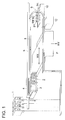
- Fig. 1 is a view showing the entire constitution of an ink-jet printer used in the present invention.
- the symbol 1 represents an ink tank to store and supply an ink containing a photopolymerizable compound.
- a constitution composed of yellow ink tank 1Y, magenta ink tank 1M, cyan ink tank 1C, and black ink tank 1K is illustrated as an example.
- the symbol 2 represents an ink-jet head having a nozzle to form an image by ejecting ink droplets onto a recording medium and incorporating yellow ink-jet head 2Y, magenta ink-jet head 2M, cyan ink-jet head 2C, and black ink-jet head 2K.
- the symbol 3 represents an actinic energy radiation source to irradiate UV radiation, that is, actinic energy radiation to an ink having been deposited on a recording medium.
- the symbol 4 represents a carriage.
- Carriage integrally holds ink-jet head 2 and energy radiation source 3 and reciprocally moves via guiding of carriage guide 5 as shown by arrow WX to scan recording medium P, and then recording medium P is driven in the arrow WY direction to form an image on recording medium P.
- a recording ink is supplied from ink tank 1 to ink-jet head 2 through ink supply path 8.
- the symbol 10 represents a maintenance unit with suction cap 9 to cap ink-jet head 2 for recovery treatment of ink-jet head 2.
- the symbol 12 represents a waste ink container to store waste ink, which receives and stores an ink having forcefully been ejected from ink-jet head 2 on flushing.
- Fig. 2 is a constitutional view showing one example of an ink supply path constitution in the ink-jet printer of the present invention.
- ink tank 101 is connected to ink supply path 102 via joint J1, and further the end portion of ink supply path 102 is connected, via joint J2, to head 104 housed in carriage 103.
- Ink droplets are ejected onto a recording medium from nozzle N of head 104 based on image forming information and then actinic energy radiation is instantaneously irradiated to the deposited ink from actinic energy radiation source L to cure the ink.
- Fig. 2b shows one example in which intermediate tank unit 105 having filter 107 built in is provided halfway in ink supply path 102.
- the discharge outlet of ink tank 101 is connected to ink supply path 102A via joint J1, which is connected to intermediate unit tank 105 via joint J3.
- An ink is sent to intermediate tank anterior chamber 106 from the joint J3 portion and then sent to intermediate tank 108 after removal of foreign substances using filter 107.
- intermediate tank 108 and ink supply path 102B are connected together via joint J4.
- Ink supply path 102B is an ink supply line to supply the thus-filtered ink stored in intermediate tank 108 to head 104.
- 109 shown in Fig. 2b represents a filter adjacent portion adjacent to filter 107.
- Fig. 2c shows an example in which instead of intermediate tank unit 105 in Fig. 2b , filter box 110 having filter 107 built in is provided.
- filter box 110 the ink inlet side is connected to ink supply path 102A via joint J5 and the ink outlet side is connected to ink supply path 102B via joint J6.
- Foreign substances in the ink are removed by filter 107 arranged in filter box 110 to send the ink to head 104.
- 111 shown in Fig. 2c represents a filter adjacent portion adjacent to filter 107.
- Fig. 2 described above, as a matter of convenience, only a line to supply an ink to a magenta ink-jet head is shown. As shown in Fig. 1 , similar supply lines are also provided for a yellow ink-jet head, a cyan ink-jet head, and a black ink-jet head. Further, in Fig. 2 , a constitution only for description is shown. Therefore, although unshown in Fig. 2 , for example, a solenoid valve to control ink sending, a branch joint, and a liquid sending pump, as well as an ink-jet head control section are provided.
- the ink-jet printer of the present invention is characterized in that for example, in the ink-jet printer or the ink supply line shown in Fig. 1 or Fig. 2 , at least a part of the surface of a metal, preferably the entire surface of the metal, constituting the liquid contact member in contact with an ink-jet ink inside an ink-jet head is subjected to passive treatment or insulating film treatment.
- a metal subjected to passive treatment or insulating film treatment is preferably composed of an alumite-treated aluminum member or an alumite-treated silicon-containing aluminum member.
- ink-jet head 2 is described below with reference to Fig. 3 - Fig. 6 .
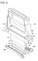
- Fig. 3 is an exploded perspective view showing ink-jet head 2 of an embodiment of the present invention.
- ink-jet head 2 of this embodiment is provided with 2 stacked ink-jet head tips (hereinafter referred to as "head tips") 41 to eject an ink.
- Head tips 41 are shaped into an elongate outline.
- a large number of ejection orifices are arranged in the bottom face (ejection face) thereof.
- ink supply opening 43 of an almost rectangular shape is provided in the exterior side of each of 2 stacked head tips 41.
- ink supply opening 43 is communication-connected to the ejection orifices via an ink flow path (unshown).
- a pressure chamber is formed, having a constitution to eject ink droplets from the ejection orifices based on pressure variation via action of piezoelectric devices.
- 2 head drive boards 46 to send control signals from the control section to each piezoelectric device are each connected to the each piezoelectric device via flexible wiring board 47.
- connection portions 49a and 49b to supply the ink via connection to ink supply opening 43 are provided in the face facing head tips 41 in manifolds 48a and 48b.
- Connection portions 49a and 49b are outlined almost similarly to the shape of ink supply opening 43.
- first concave portions 491a and 491b serving as ink supply paths are provided in the interior thereof.
- connection portions 49a and 49b dividing walls 492a and 492b are horizontally formed in plates to vertically divide first concave portions 491a and 491b and at the same time, to ensure communicative connection of the upper part and the lower part of divided first concave portions 491a. and 491b.
- blocking walls 493a and 493b formed into an L-letter shape are provided in the rear upper part of connection portions 49a and 49b, and second concave portions 494a and 494b are formed to be blocked from first concave portions 491a and 491b by blocking walls 493a and 493b.
- connection portions 49a and 49b provided are third concave portions 50a and 50b blocked from first concave portions 491a and 491b and second concave portions 494a and 494b.
- injection openings 481a and 481b are provided to inject an ink into first concave portions 491a and 491b via communicative connection to the lower part of first concave portions 491 a and 491b.
- first communicative connection openings 482a and 482b are provided for communicative connection to the upper part of first concave portions 491a and 491b.
- Injection openings 481a and 481b and first communicative connection openings 482a and 482b are arranged in an anteroposterior manner so as for injection openings 481a and 481b to be located forward.
- first bed sections 484a and 484b of first communicative connection openings 482a and 482b extend almost horizontally.
- Vertical first side walls 485a and 485b are formed on the opposite side of head tips 41 in first bed sections 484a and 484b and ink receiving sections 483a and 483b.
- cleaning piping arrangements 486a and 486b extending toward the outside are provided to clean the interior of an ink flow path via communicative connection to third concave portions 50a and 50b immediately after setting up ink-jet head 2.
- second communicative connection openings 487a and 487b which are communication-connected to second concave portions 494a and 494b.
- second bed sections 488a and 488b of second communicative connection openings 487a and 487b extend almost horizontally.
- Vertical second side walls 489a and 489b are formed on the opposite side of head tips 41 in second bed sections 488a and 488b.
- engaging pieces 490a and 490b are provided to clip and fasten head tips 41.
- Engaging piece 490a of manifold 48a, being one, and engaging piece 490b of manifold 48b, being the other, are engaged together to mount 2 manifolds 48a and 48b to head tips 41.
- filters 51a and 51b are provided to cover first concave portions 491a and 491b and second concave portions 494a and 494b and to make contact with dividing walls 492a and 492b and blocking walls 493a and 493b.
- filters 51a and 51b cover ink supply opening 43 of head tips 41.
- spaces 52a and 52b (refer to Fig. 7 ) between ink supply opening 43 and filters 51a and 51b. Spaces 52a and 52b serve as ink flow paths to introduce an ink having been filtered by filters 51a and 51b to ink supply opening 43.
- an unshown holding plate is mounted in order to hold manifolds 48a and 48b and head tips 41 so as for the ejection face to be exposed.
- chassis hereinafter also referred to as "chassis frame" 54 to which components of ink-jet head 2 such as head tips 41, manifolds 48a and 48b, head drive boards 46, and the holding plate as described above are mounted and fastened.
- Chassis frame 54 is covered with an unshown cover.
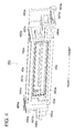
- Fig. 6 is a bottom view of chassis frame 54.
- two side plates 55 are formed to cover both sides of manifolds 48a and 48b.
- first contact wall 56 in close contact with the front end portion of ink receiving sections 483a and 483b of manifolds 48a and 48b; and second contact wall 57 in close contact with the front end portion of first bed sections 484a and 484b of manifolds 48a and 48b in the rear of first contact wall 56.
- Gaps Hl are formed between both end portions of first contact wall 56 and second contact wall 57 and side plate 55 so as only for first side walls 485a and 485b of manifolds 48a and 48b to enter. When having entered into gaps H1, first side walls 485a and 485b are brought into close contact with both end portions of first contact wall 56 and second contact wall 57.
- chassis frame 54 there is provided, between 2 side plates 55, third contact wall 58 in contact with the rear end portions of second bed sections 488a and 488b of manifolds 48a and 48b. Between both end portions of third contact wall 58 and side plates 55, gaps H2 are formed so as only for second side walls 489a and 489b of manifolds 48a and 48b to enter. When having entered into gaps H2, second side walls 489a and 489b are brought into close contact with both end portions of third contact wall 58.
- ink supply space I a space formed by first side walls 485a and 485b and ink receiving sections 483a and 483b of manifolds 48a and 48b, as well as first contact wall 56 and second contact wall 57 is referred to as ink supply space I (refer to Fig. 7 ), whereby ink supply space I is communication-connected to injection openings 481a and 481b of manifolds 48a and 48b.
- chassis frame 54 ink supply flow path 59 is provided to supply an ink to injection openings 481a and 481b via communicative connection to ink supply space I. In this manner, ink supply flow path 59 and injection openings 481a and 481b are connected together via ink supply space I.
- ink supply flow path 59 is provided in the front end portion of chassis frame 54 and is communication-connected to ink connection portion 60 of a cylindrical shape connected to ink supply pipe 6.
- first communicative connection space Sl a space formed by first side walls 485a and 485b and first bed sections 484a and 484b of manifolds 48a and 48b, as well as second contact wall 57 is referred to as first communicative connection space Sl (refer to Fig. 7 ), whereby first communicative connection space Sl is communication-connected to first communicative connection openings 482a and 482b of manifolds 48a and 48b.
- First communicative connection flow path 61 is provided in chassis frame 54 to communication-connect the air to first communicative connection openings 482a and 482b via communicative connection to first communicative connection space Sl.
- first communicative connection flow path 61 and first communicative connection openings 482a and 482b are connected together via first communicative connection space S1.
- first communicative connection flow path 61 is provided in the vicinity of ink connection portion 60 and communication-connected to first pump connection portion 62 of a cylindrical shape connected to a first pump (unshown) to negatively pressurize the interior of manifolds 48a and 48b.
- a conventionally known check valve (unshown) is provided to prevent the ink inside the flow path from flowing back to the manifold interior.
- second communicative connection space S2 (refer to Fig. 7 ), whereby second communicative connection space S2 is communication-connected to second communicative connection openings 487a and 487b of manifolds 48a and 48b.
- Second communicative connection flow path 63 is provided in chassis frame 54 to communication-connect the air to second communicative connection openings 487a and 487b via communicative connection to second communicative connection space S2.
- second communicative connection flow path 63 and second communicative connection openings 487a and 487b are connected together via second communicative connection space S2.
- second communicative connection flow path 63 is provided in the rear end portion of manifolds 48a and 48b and communication-connected to second pump connection portion 64 of a cylindrical shape connected to a second pump (unshown) to negatively pressurize the interior of manifolds 48a and 48b.
- a conventionally known check valve (unshown) is provided to prevent the ink in the flow path from flowing back to the manifold interior.
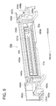
- Fig. 7 is a schematic view showing an outline of each flow path formed in ink-jet head 2.
- ink-jet head 2 An ink is supplied from ink tank 5 and then the ink flows into ink-jet head 2 via ink supply pipe 6 by initiating the ink supply pump.
- ink-jet head 2 initially, the ink passes through ink supply flow path 59 and reaches ink supply space I, and then divergingly enters into injection openings 481a and 481b of manifolds 48a and 48b.
- the ink passes through filters 51a and 51b and flows to spaces 52a and 52b.
- the ink having reached spaces 52a and 52b enters into head tips 41 from ink supply opening 43.
- first communicative connection flow path 61 is communication-connected to the upstream side of filters 51a and 51b.
- Second communicative connection flow path 63 is communication-connected to the downstream side of filters 51a and 51b.
- the ink-jet head of the present invention is characterized in that the surface of a metal constituting a liquid contact member in contact with an ink-jet ink inside an ink-jet head is at least partially subjected to passive treatment or insulating film treatment.
- An ink contact member a part of which is composed of a metal includes the manifold (48), the connection portion (49), the filter (51), and the chassis frame (54).
- Metal members constituting the ink-jet head of the present invention include metallic materials, which are also commonly applied to form structural objects. Specifically, there can be used iron, aluminum, zirconium, copper, nickel, tin, zinc, lead, silver, gold, alloys thereof, and alloys employing other metals. Of these, preferable are stainless steel, aluminum, zirconium, copper, and brass. Stainless steel and aluminum are more preferable from the viewpoint of processability, handling properties, and cost.
- stainless steel ferritic stainless steel and austenitic stainless steel are used. These stainless steels inherently have a Cr/Fe atomic ratio of about 0.7 - 1.2 on the surface thereof. In the present invention, those allowed to have at least 2.0 for this atomic ratio are used.
- Passive treatment referred to in the present invention is treatment for producing a state in which a metal losses its expected chemical reactivity. For example, as soon as iron is immersed in a concentrated nitric acid, the iron becomes hard to dissolve, whereby no copper is precipitated even when the iron is placed in a copper sulfate solution. In this case, the iron is said to become passive.
- passive treatment examples include acid treatment or acid generating treatment in which stainless steel is immersed in a concentrated nitric acid or a chromic acid solution; fluorinated passive treatment in which an oxide film on the surface of stainless steel is removed and then fluorine gas treatment is carried out at 265°C or lower; and Cr 2 O 3 passive treatment employing chromic acid.
- acid treatment is desirably carried out using an acid aqueous solution enabling to remove stains, rust, and scale remaining on the stainless steel surface, preferably using a nitric acid solution mainly.
- any appropriate passive treatment other than the above passive treatments may be carried out.
- Passive treatment for aluminum includes alumite treatment and glass coating treatment.
- Alumite is a material in which aluminum is coated with an anticorrosive oxide film via anodization.
- the oxide film is mainly composed of Al 2 O 3 , depending on the treatment.
- alumite treatment is a method in which aluminum is immersed in oxalic acid, sulfuric acid, or a chromic acid solution and then anodized to have an anticorrosive oxide film coated thereon, being used for building materials and containers. These are technologies to extremely enhance anticorrosive properties and insulating properties of the aluminum surface.
- sealing treatment is preferably carried out further. This sealing treatment is treatment to seal porous portions.
- Glass coating treatment is treatment in which sodium silicate, referred to as liquid glass, is sintered on the surface of aluminum and used for reflectance enhancement of luminaires using a technology to dry a concentrated aqueous solution of an alkali silicate obtained by melting silicon dioxide and an alkali on the surface of aluminum.
- a resin coating treatment is preferably exemplified.
- the resin coating treatment for example, TEFLON (a registered trademark) coating and ceramic coating are preferably listed with no specific limitation.
- PI polyimide
- PAI polyamideimide
- epoxy resin an epoxy resin
- TEFLON (a registered trademark) coating is specifically preferable.
- a metal subjected to a passive treatment or an insulating film treatment is preferably an alumite-treated aluminum member or an alumite-treated silicon-containing aluminum member.
- An alumite-treated aluminum member according to the present invention will now be described.
- aluminum produces a thin oxide film even on an untreated surface thereof by air oxidation, and thereby is highly resistant to corrosion, compared to iron, being, however, the metal exhibiting relatively low abrasion resistance and low environmental soundness.
- an anodization (alumite) treatment is carried out as a method to improve these properties.
- the anodization (alumite) of aluminum referred to in the present invention is a method in which aluminum serving as an anode is electrolyzed to form an oxide film having a unique shape on the aluminum surface.
- An alumite film obtained via such anodization exhibits excellent adhesion properties and uniformity.
- the film thickness thereof is determined based on electrolysis conditions and duration. Accordingly, a desired film thickness can be obtained, compared to an electroplating method.
- a substrate composed of aluminum or an aluminum alloy as an anode is generally electrolyzed in an acid bath such as chromic acid, sulfuric acid, boric acid, or sulfamic acid to form an oxide film on the substrate surface.
- an acid bath such as chromic acid, sulfuric acid, boric acid, or sulfamic acid to form an oxide film on the substrate surface.
- Treatment conditions for this anodization are not simply specified, since optimum conditions depend on the electrolyte used. Generally, the following ranges are appropriate: the electrolyte concentration is 1 - 80% by mass; the liquid temperature is 5 - 70 °C; the current density is 0.5 60 A/dm 2 ; the voltage is 1 - 100 V; and the electrolysis duration is 10 seconds -. 10 hours.
- an aluminum substrate Prior to the anodization treatment, an aluminum substrate is preferably subjected to a degreasing treatment via degreasing cleaning methods using various materials such as an acid, an alkali, an organic solvent, and a surfactant. Further, subsequently, the surface thereof is also preferably subjected to etching treatment using an alkali, an acid, or a fluoride.
- aluminum alloys can be used for a substrate.
- a metal such as silicon, copper, manganese, magnesium, chromium, zinc, lead, bismuth, nickel, titanium, or iron with aluminum.
- the composition thereof is not specifically limited and those known in the art and commonly used can be employed.
- an aluminum alloy having a large content of silicon is more preferable.
- treatment duration for common alumite processing as described above may increase extremely or the surface may become nonuniform.
- an aluminum member is an alumite-treated silicon-containing aluminum member.
- the silicon content is preferably at least 10%, specifically preferably at least 20%.
- the alumite film thickness of the alumite-treated aluminum member and the alumite-treated silicon-containing aluminum member is preferably at least 9 ⁇ m.
- an aluminum member as an object to be tested entirely subjected to the alumite treatment is immersed in a test solution of 25 °C prepared by dripping a few drops of a 1% by mass solution of phenolphthalein into a 0.2% by mass solution of NaCl.
- the alumite-treated aluminum member and a stainless steel plate are arranged as a cathode and an anode, respectively, and then a voltage of 2.0 V is applied for 90 seconds between the electrodes.
- a voltage of 2.0 V is applied for 90 seconds between the electrodes.
- the presence or absence of bubble generation from the surface of the alumite-treated aluminum member, or occurrence or no occurrence of color change of the test solution is visually observed.
- An ink containing a photopolymerizable compound according to the present invention contains a cationically polymerizable composition or a radically polymerizable composition.
- an ink containing a cationically polymerizable composition is preferably employed.
- An ink containing a cationically polymerizable composition according to the present invention contains a cationically curable monomer (a cationically polymerizable compound) and a photopolymerization initiator.
- a cationically curable monomer (a cationically polymerizable compound) preferably contains at least one compound selected from compounds containing an oxetane ring and epoxy compounds, and more preferably contains a vinyl ether compound.
- an oxetane compound having at least one oxetane ring substituted at the 2-position represented by following Formula (14) in the molecule is preferably used.
- R 1 - R 6 each represent a hydrogen atom or a substituent.
- at least one group represented by R 3 -, R 6 is a substituent.
- the substituents represented by R 1 - R 6 represent, for example, a fluorine atom, an alkyl group of a carbon atom number of 1 - 6 (e.g., a methyl group, ethyl group, propyl group, or butyl group), a fluoroalkyl group of a carbon atom number of 1 - 6, an allyl group, an aryl group (e.g., a phenyl group or naphthyl group), a furyl group, or a thienyl group. These groups may further have a substituent.
- R 1 - R 6 each represent a hydrogen atom or a substituent
- R 7 and R 8 each represent a substituent
- Z's each are independent, representing an oxygen or sulfur atom, or a divalent hydrocarbon group which may contain an oxygen or sulfur atom in the main chain.
- the substituents represented by R 1 - R 6 in Formulas (15) - (18) are synonymous with the substituents represented by R 1 - R 6 in Formulas (14).
- the substituents represented by R 7 and R 8 represent an alkyl group of a carbon atom number of 1 - 6 (such as, a methyl group, ethyl group, propyl group, and butyl group), an alkenyl group of a carbon atom number of 1 - 6 (such as, a I-propeny group, 2-propenyl group, 2-methyl-1-propenyl group, 2-methyl-2-propenyl group, 1-butenyl group, 2-butenyl group, and 3-butenyl group), an aryl group (such as, a phenyl group and naphthyl group), an aralkyl group (such as, a benzyl group, fluorobenzyl group, and methoxybenzyl group), an acyl group of a carbon atom number of 1 - 6 (such as, a propylcarbonyl group, butylcarbonyl group, and pentylcarbonyl group),
- Formulas (15) - (18) as an oxygen atom or a sulfur atom, or divalent hydrocarbon groups which may contain an oxygen or sulfur atom in the main chain represented by Z in Formulas (15) - (18) include an alkylene group (such as, an ethylene group, trimethylene group, tetramethylene group, propylene group, ethylethylene group, pentamethylene group, hexamethylene group, heptamethylene group, octamethylene group, nonamethylene group, and decamethylene group), an alkenylene group (such as, a vinylene group and propenylene group), and an alkynylene group (such as, an ethynylene group and 3-pentynylene group). Further, the carbon atoms of the above alkylene group, alkenylene group, and alkynylene group may be substituted with an oxygen atom or a sulfur atom.
- an alkylene group such as, an ethylene group, trimethylene group, tetramethylene group
- R 1 is preferably a lower alkyl group (such as, a methyl group, ethyl group, and propyl group), and an ethyl group is specifically preferably used.
- R 7 and R 8 preferable is a propyl group, a butyl group, a phenyl group, or a benzyl group.
- Z is preferably a hydrocarbon group (such as, an alkylene group, alkenylene group, and alkynylene group) containing no oxygen or sulfur atom.
- compounds having at least 2 oxetane rings in the molecule as represented by following Formulas (19) and (20) can be used.
- Z is synonymous with the group referred to in any of above Formulas (15) - (18);
- m represents 2, 3, or 4;
- R 1 - R 6 represent a hydrogen atom, a fluorine atom, an alkyl group of a carbon atom number of 1 - 6 (e.g., a methyl group, ethyl group, propyl group, or butyl group), a fluoroalkyl group of a carbon atom number of 1 - 6, an allyl group, an aryl group (e.g., a phenyl group or naphthyl group), or a furyl group.
- Z is synonymous with the group referred to in any of above Formulas (15) - (18);
- m represents 2, 3, or 4;
- R 1 - R 6 represent a hydrogen atom, a fluorine atom, an alky
- R 3 - R 6 is a substituent, and wherein R 9 represents a linear or branched alkylene group of a carbon atom number of 1 - 12, a linear or branched poly(alkyleneoxy) group, or a divalent group selected from the group consisting of those represented by following Formulas (22), (23), and (24).
- an alkylene group represented by following Formula (21) is preferably used.
- R 10 represents a lower alkyl group (e.g., a methyl group, ethyl group, or propyl group).
- n represents an integer of 0 - 2000
- R 12 represents an alkyl group of a carbon atom number of 1 - 10 (e.g., a methyl group, ethyl group, propyl group, butyl group, pentyl group, hexyl group, heptyl group, octyl group, or nonyl group)
- R 11 represents an alkyl group of a carbon atom number of 1 - 10 (e.g., a methyl group, ethyl group, propyl group, butyl group, pentyl group, hexyl group, heptyl group, octyl group, or nonyl group) or a group represented by following Formula (25).
- R 13 represents an alkyl group of a carbon atom number of 1 - 10 (e.g., a methyl group, ethyl group, propyl group, butyl group, pentyl group, hexyl group, heptyl group, octyl group, or nonyl group).
- R 14 represents a hydrogen atom, an alkyl group of a carbon atom number of 1 - 10 (e.g., a methyl group, ethyl group, propyl group, butyl group, pentyl group, hexyl group, heptyl group, octyl group, or nonyl group), an alkoxy group of a carbon atom number of 1 - 10 (e.g., a methoxy group, ethoxy group, propoxy group, butoxy group, or pentoxy group), a halogen atom (e.g., a fluorine atom, chlorine atom, bromine atom, or iodine atom), a nitro group, a cyano group, a mercapto group, an alkoxycarbonyl group (e.g., a methyloxycarbonyl group, ethyloxycarbonyl group, or butyloxycarbonyl group), or a carboxyl group.
- R 15 represents an oxygen atom, a sulfur atom, - NH-, -SO-, -SO 2 -, -(CH 2 )-, -C(CH 3 ) 2 - , or -(CF 3 ) 2 -.
- R 1 in above Formulas (19) and (20) is preferably a lower alkyl group (e.g., a methyl group, ethyl group, or propyl group).
- An ethyl group is specifically preferable.
- R 9 is preferably a hexamethylene group.
- those having R 14 as a hydrogen atom in Formula (23) are preferably used.
- R 10 is preferably an ethyl group.
- R 12 and R 13 each are preferably a methyl group and z is preferably a hydrocarbon group containing no oxygen or sulfur atom.
- a compound represented by following Formula (26) is cited.
- r represents an integer of 25 - 200 and R 16 represents an alkyl group of a carbon atom number of 1 - 4 (e.g., a methyl group, ethyl group, propyl group, or butyl group) or a trialkylsilyl group.
- R 1 , R 3 , R 5 , and R 6 are synonymous with the substituents represented by R 1 - R 6 in above Formulas (14).
- at least one of R 3 - R 6 is a substituent.
- a compound having an oxetane ring substituted at the 2-position according to the present invention can be synthesized by referring to the literatures listed below.
- the content of a compound having an oxetane ring substituted at least at the 2-position according to the present invention in a cationically polymerizable ink is preferably 1 - 97% by mass, more preferably 30 - 95% by mass.
- these compounds having an oxetane ring substituted at least at the 2-position according to the present invention may be used individually or 2 types thereof of different structure may be combined.
- combined use with a photopolymerizable monomer or a polymerizable monomer to be described later is possible.
- the mixing ratio of a compound having an oxetane ring substituted at least at the 2-position is preferably adjusted to be 10 -98% by mass in a mixture, and the mixing ratio of an added photopolymerizable compound such as a photopolymerizable monomer or polymerizable monomer is preferably adjusted to be 2 - 90% by mass.
- the above oxetane compound having a substituent at the 2-position and a conventionally known oxetane compound can be used in combination.
- an oxetane compound having a substituent only at the 3-position can preferably be used in combination.
- R 1 represents a hydrogen atom, an alkyl group of a carbon atom number of 1 - 6 such as a methyl group, ethyl group, propyl group, or butyl group, a fluoroalkyl group of a carbon atom number of 1 - 6, an allyl group, an aryl group, a furyl group, or a thienyl group
- R 2 represents an alkyl group of a carbon atom number of 1 - 6 such as a methyl group, ethyl group, propyl group, or butyl group, an alkenyl group of a carbon atom number of 2 - 6 such as a 1-propeny group, 2-propenyl group, 2-methyl-1-propenyl group, 2-methyl-2-propenyl group, 1-butenyl group, 2-butenyl group, or 3-
- R 1 represents the same group as in Formula (27); and R 3 represents, for example, a linear or branched alkylene group such as an ethylene group, propylene group, or butylene group, a linear or branched poly(alkyleneoxy) group such as a poly(ethyleneoxy) group or poly(propyleneoxy) group, or a linear or branched unsaturated hydrocarbon group such as a propenylene group, methylpropenylene group, or butenylene group; or a carbonyl group, an alkylene group containing a carbonyl group, an alkylene group containing a carboxyl group, or an alkylene group containing a carbamoyl group.
- a linear or branched alkylene group such as an ethylene group, propylene group, or butylene group
- a linear or branched poly(alkyleneoxy) group such as a poly(ethyleneoxy) group or poly(propyleneoxy) group
- R 3 a multivalent group selected from the groups represented by following Formulas (29), (30), and (31) can be cited.
- R 4 represents a hydrogen atom, an alkyl group of a carbon atom number of 1 - 4 such as a methyl group, ethyl group, propyl group, or butyl group, an alkoxy group of a carbon atom number of 1 - 4 such as a methoxy group, ethoxy group, propoxy group, or butoxy group, a halogen atom such as a chlorine atom or bromine atom, a nitro group, a cyano group, a mercapto group, a lower alkoxycarbonyl group, a carboxyl group, or a carbamoyl group.
- R 5 represents an oxygen atom, a sulfur atom, a methylene group, NH, SO, SO 2 , (CF 3 ) 2 , or C(CH 3 ) 2 .
- R 6 represents an alkyl group of a carbon atom number of 1 - 4 such as a methyl group, ethyl group, propyl group, or butyl group, or an aryl group
- n represents an integer of 0 - 2000
- R 7 represents an alkyl group of a carbon atom number of 1 - 4 such as a methyl group, ethyl group, propyl group, or butyl group, or an aryl group and further R 7 can include a group selected from a group represented by following Formula (32).
- R 8 represents an alkyl group of a carbon atom number of 1 - 4 such as a methyl group, ethyl group, propyl group, or butyl group, or an aryl group; and m represents an integer of 0 - 100.
- Exemplified compound 1 is a compound wherein R 1 is an ethyl group and R 3 is a carboxyl group in above Formula (28).
- exemplified compound 2 is a compound wherein in Formula (28), R 1 is an ethyl group and R 3 is a group in which R 6 and R 7 are a methyl group in above Formula (31); and n is 1.
- R 1 is synonymous with R 1 of above Formula (27).
- R 1 is synonymous with R 1 of above Formula (27).
- R 9 includes, for example, a branched alkylene group of a carbon atom number of 1 - 12 such as the groups represented by following A - C; a branched poly(alkyleneoxy) group such as the group represented by following D; and a branched polysiloxy group such as the group represented by following E.
- the designation j represents 3 or 4.
- R 10 represents a lower alkyl group such as a methyl group, ethyl group, or propyl group.
- p represents an integer of 1 - 10.
- R 8 is synonymous with R 8 of above Formula (32).
- R 11 represents an alkyl group of a carbon atom number of 1 - 4 such as a methyl group, ethyl group, propyl group, or butyl group, or a trialkylsilyl group and r represents 1 - 4.
- oxetane compound of the present invention include exemplified compounds 4, 5, and 6 listed below.
- a production method for each of the oxetane ring-containing compound is not specifically limited and it is only necessary to employ any appropriate method conventionally known in the art.
- an oxetane ring synthesis method from a diol disclosed by Pattison ( D. B. Pattison, J. Am. Chem. Soc., 3455, 79 (1957 )).
- listed are compounds having 1 - 4 oxetane rings having relatively high molecular weight of a molecular weight of about 1000 - 5000.
- these compounds following exemplified compounds 7, 8, and 9 are cited.
- any of a monomer of a compound having an epoxy group and an oligomer thereof can be used.
- a conventionally known aromatic epoxy compound, alicyclic epoxy compound, and aliphatic epoxy compound are listed.
- such epoxy compounds refer to monomers or oligomers thereof.
- a compound of lower molecular weight is preferable and an oligomer featuring a molecular weight of less than 1000 is preferable.
- Preferable aromatic epoxy compounds are di- or polyglycidyl ethers produced via reaction of polyphenols having at least one aromatic nucleus or alkylene oxide adducts thereof with epichlorohydrin.
- polyphenols having at least one aromatic nucleus or alkylene oxide adducts thereof with epichlorohydrin there are listed, for example, di- or polyglycidyl ethers of bisphenol A or alkylene oxide adducts thereof; di- or polyglycidyl ethers of hydrogenated bisphenol A or alkylene oxide adducts thereof; and novolac-type epoxy resins.
- the alkylene oxide includes ethylene oxide and propylene oxide.
- cyclohexene oxide- or cyclopentene oxide-containing compounds obtained by epoxidizing compounds having at least one cyclohexene ring or cyclopentene ring using an appropriate oxidant such as hydrogen peroxide or a peracid. Specific examples include compounds listed later.
- Preferable aliphatic epoxy compounds include di- or polyglycidyl ethers of aliphatic polyhydric alcohols or alkylene oxide adducts thereof.
- Typical examples thereof include diglycidyl ethers of alkylene glycols such as diglycidyl ethers of ethylene glycol, diglycidyl ethers of propylene glycol, or diglycidyl ethers of 1,6-hexanediol; polyglycidyl ethers of polyhydric alcohols such as di- or triglycidyl ethers of glycerin or alkylene oxide adducts thereof; and diglycidyl ethers of polyalkylene glycols such as diglycidyl ethers of polyethylene glycol or alkylene oxide adducts thereof or diglycidyl ethers of polypropylene glycol or alkylene oxide adducts thereof.
- the alkylene oxide includes ethylene oxide and propylene oxide
- monoglycidyl ethers of aliphatic higher alcohols being monomers having one oxirane ring in the molecule and monoglycidyl ethers of phenol or cresol can also be used.
- aromatic epoxy compounds and alicyclic epoxy compounds are preferable and the alicyclic epoxy compounds are specifically preferable.
- the above epoxy compounds may be used individually or at least 2 types thereof may be used in appropriate combination.
- the content thereof is preferably allowed to be 10 - 80% by mass. In the case of less than 10% by mass, curability markedly varies with curing ambiences (temperature and humidity), resulting in no practical use. In the case of more than 80% by mass, physical film properties after curing degrades, resulting in no practical use.
- one type of alicyclic epoxy compound may be used individually or at least 2 types may be used in appropriate combination.
- a cationically polymerizable composition according to the present invention contains an epoxidized fatty acid eater or epoxidized fatty acid glyceride as an epoxy compound.
- Such an epoxidized fatty acid eater or epoxidized fatty acid glyceride is preferably used in combination in an oxetane compound/alicyclic epoxy compound system, from the viewpoint of safety and environment such as AMES, sensitizing properties, skin irritating properties, and odor.
- AMES oxetane compound/alicyclic epoxy compound system
- an epoxidized fatty acid ester or an epoxidized fatty acid glyceride usable for the present invention those prepared by introducing an epoxy group into a fatty acid ester or a fatty acid glyceride are used with no specific limitation.
- Such an epoxidized fatty acid ester is one produced by epoxidizing an oleic acid ester. Methyl epoxystearate, butyl epoxystearate, or octyl epoxystearate is used. Further, an epoxidized fatty acid glyceride is one produced also by epoxidizing soy bean oil, linseed oil, or castor oil. Epoxidized boy bean oil, epoxidized linseed oil, or epoxidized castor oil is used.
- Vinyl ether compounds usable for the present invention include, for example, di- or trivinyl ether compounds such as ethylene glycol divinyl ether, diethylene glycol divinyl ether, triethylene glycol divinyl ether, propylene glycol divinyl ether, dipropylene glycol divinyl ether, butanediol divinyl ether, hexanediol divinyl ether, cyclohexanedimethanol divinyl ether, or trimethylolpropane trivinyl ether; and monovinyl ether compounds such as ethyl vinyl ether, butyl vinyl ether, i-butyl vinyl ether, octadecyl vinyl ether, cyclohexyl vinyl ether, hydroxybutyl vinyl ether, 2-ethylhexyl vinyl ether, cyclohexanedimethanol monovinyl ether, propyl vinyl ether, i-propyl vinyl ether
- vinyl ether compounds in view of curability, adhesion properties, and surface hardness, di- or trivinyl ether compounds are preferable. Divinyl ether compounds are specifically preferable. In the present invention, such vinyl ether compounds may be used individually or at least two types thereof may be used in combination.
- an onium salt can be used as a cationic polymerization initiator (also referred to simply as a photopolymerization initiator).
- a cationic polymerization initiator also referred to simply as a photopolymerization initiator.
- Such an onium salt includes a sulfonium salt, an oxonium salt, and an iodonium salt.
- sulfonium salt compounds represented by following Formulas [1] - [4] are preferable.
- R 31 - R 47 each represent a hydrogen atom or a substituent.
- R 31 - R 33 do not represent a hydrogen atom simultaneously;
- R 34 - R 37 do not represent a hydrogen atom simultaneously;
- R 38 - R 41 do not represent a hydrogen atom simultaneously;
- R 42 - R 47 do not represent a hydrogen atom simultaneously.
- the substituent represented by R 31 - R 47 preferably includes an alkyl group such as a methyl group, ethyl group, propyl group, isopropyl group, butyl group, isobutyl group, t-butyl group, pentyl group, or hexyl group; an alkoxy group such as a methoxy group, ethoxy group, propoxy group, butoxy group, hexyloxy group, decyloxy group, or dodecyloxy group; a carbonyl group such as an acetoxy group, propionyloxy group, decylcarbonyloxy group, dodecylcarbonyloxy group, methoxycarbonyl group, ethoxycarbonyl group, or benzoyloxy group; a phenylthio group; a halogen atom such as fluorine, chlorine, bromine, or iodine; a cyano group; a nitro group; and a hydroxyl
- X 31 represents a non-nucleophilic anionic residue, including, for example, a halogen atom such as F, Cl, Br, or I, B(C 6 F 5 ) 4 , R 18 COO, R 19 SO 3 , SbF 6 , AsF 6 , PF 6 , and BF 4 .
- a halogen atom such as F, Cl, Br, or I
- B(C 6 F 5 ) 4 R 18 COO, R 19 SO 3 , SbF 6 , AsF 6 , PF 6 , and BF 4 .
- R 18 and R 19 each represent an alkyl group such as a methyl group, ethyl group, propyl group, or butyl group; and an alkyl group or a phenyl group which can be substituted with a halogen atom such as fluorine, chlorine, bromine, or iodine, a nitro group, a cyano group, or an alkoxy group such as a methoxy group or ethoxy group.
- a halogen atom such as fluorine, chlorine, bromine, or iodine
- a nitro group such as a cyano group
- an alkoxy group such as a methoxy group or ethoxy group.
- B(C 6 F 5 ) 4 and PF 6 are preferable.
- any of the sulfonium salts represented by above Formulas [1] - [4] is specifically preferably at least one type selected from the sulfonium salts represented by following Formulas [5] - [13] .
- X 31 represents a non-nucleophilic anionic residue as described above.
- any of the sulfonium salts represented by above Formulas [1] - [4] is specifically preferably at least one type selected from the sulfonium salts represented by Formulas [5] - [13].
- X represents a non-nucleophilic anionic residue as described above.
- the cationically polymerizable composition of the present invention preferably contains an onium salt at 1% by mass - less than 5% by mass as a photopolymerization initiator.
- An ink containing a radically polymerizable composition according to the present invention contains a radically curable monomer (a radically polymerizable monomer) and a photoradical polymerization initiator as a radically polymerizable composition (an actinic radiation curable composition or a photopolymerizable compound).
- a radically polymerizable monomer according to the present invention is a compound having a radically polymerizable ethylenically-unsaturated bond.
- Any compound having at least one radically polymerizable ethylenically-unsaturated bond in the molecule may be usable, including a chemical form such as a monomer, oligomer, and polymer.
- Such a radically polymerizable monomer may be used individually, or combined use of at least 2 types at an appropriate ratio is applicable to enhance the targeted characteristics.
- Examples of the compound having a radically polymerizable ethylenically-unsaturated bond includes unsaturated acids such as acrylic acid, methacrylic acid, itaconic acid, crotonic acid, isocrotonic acid, or maleic acid; salts, esters, urethanes, amides, and anhydrides thereof; acrylonitrile; and styrene, as well as various types of radically polymerizable compounds such as unsaturated polyesters, unsaturated polyethers, unsaturated polyamides, and unsaturated urethanes.
- unsaturated acids such as acrylic acid, methacrylic acid, itaconic acid, crotonic acid, isocrotonic acid, or maleic acid
- salts, esters, urethanes, amides, and anhydrides thereof acrylonitrile
- styrene as well as various types of radically polymerizable compounds such as unsaturated polyesters, unsaturated polyethers, unsaturated
- acrylic acid derivatives such as 2-ethylhexyl acrylate, 2-hydroxyethyl acrylate, butoxyethyl acrylate, carbitol acrylate, cyclohexyl acrylate, tetrahydrofurfuryl acrylate, benzyl acrylate, bis(4-acryloxypolyethaxyphenyl)prapane, neopentylglycol diacrylate, 1,6-hexanediol diacrylate, ethylene glycol diacrylate, diethylene glycol diacrylate, triethylene glycol diacrylate, tetraethylene glycol diacrylate, polyethylene glycol diacrylate, polypropylene glycol diacrylate, pentaerythritol triacrylate, pentaerythritol tetraacrylate, dipentaerythritol tetraacrylate, trimethylolpropane triacrylate, tetramethylolmethane
- radically polymerizable and cross-linkable monomers, oligomers, and polymers commercially available or known in the art described, specifically, in " Kakyozai Handbook (Handbook of Crosslinking Agents),” edited by Shinzo Yamashita (1981, Taisei Sha ); “ UV-EB Kohka Handbook (Genryo Hen)(UV ⁇ EB Curing Handbook (Raw Materials Part),” edited by Kiyoshi Kato (1985, Kohbunshi Kankoh Kai ); “ UV-EB Kohka Gijutsu no Ohyoh to Shijoh (Application and Market of UV ⁇ EB Curing Technology)", edited by Rad Tech Japan, page 79 (1989, CMC ); and Eiichiroh Takiyama, “Polyester Jushi Handbook (Handbook of Polyester Resins)” (1988, Nikkan Kogyo Shimbun Ltd. ).
- the amount of any of the above radically polymerizable compounds added is preferably 1 - 97% by mass, more preferably 30
- radical polymerization initiators there are listed triazine derivatives described in Examined Japanese Patent Application Publication (hereinafter referred to as JP-B) Nos. 59-1281 and 61-9621 and JP-A 60-60104 ; organic peroxides described in JP-A Nos. 59-1504 and 61-243807 ; diazonium compounds described in JP-B Nos. 43-23684 , 44-6413 , 44-6413 , and 47-1604 , and U.S. Patent No. 3,567,453 specification; organic azide compounds described in U.S. Patent Nos.
- An ink containing a photopolymerizable compound according to the present invention preferably contains a pigment as a colorant.
- Pigments preferably used in the present invention will now be listed:
- a ball mill a sand mill, an atriter, a roll mill, an agitator, a Henschel mixer, a colloid mill, an ultrasonic homogenizer, a pearl mill, a wet-type jet mill, or a paint shaker.
- a dispersion medium photopolymerizable compounds and of these, monomers having the lowest viscosity are preferably selected in view of dispersion adaptability.
- the average particle diameter of pigment particles is preferably 0.08 - 0.5 ⁇ m.
- a pigment, a dispersion agent, and a dispersion medium are appropriately selected and also dispersion and filtration conditions are appropriately set. This particle diameter control makes it possible to inhibit head nozzle clogging and to maintain ink storage stability, ink transparency, and curing sensitivity.
- the concentration of a colorant is preferably 1% by mass - 10% by mass based on the entire ink amount.
- pigment dispersion agent those having a basic anchor portion are preferably used. Further, polymer dispersion agents having a comb-like structure are more preferably used.
- pigment dispersion agent usable for the present invention examples include SOLSPERSE 9000, 17000, 18000, 19000, 20000, 24000SC, 24000GR, 28000, and 32000 (produced by Avecia Co.); AJISPER PB821 and PB822 (produced by Ajinomoto-Fine-Techno Co., Inc.); PLAAD ED214 and ED251 and DISPARLON DA-325 and DA-234 (produced by Kusumoto Chemicals Ltd.); and EFKA-5207, 5244, 6220, and 6225 (produced by EFKA Co.).
- a pigment derivative (a synergist) can be used together with a pigment dispersion agent.
- Specific examples of such a pigment derivative include SOLSPERSE 5000, 12000, and 22000 (produced by Avecia Co.) and EFKA-6746 and EFKA-6750 (produced by EFKA Co.).
- An ink-jet ink according to the present invention preferably employs an actinic radiation curable-type composition and its viscosity is preferably in the range of 10 mPas - less than 50 mPas at 25 °C. It is preferable that the viscosity be at least 10 mPas to produce the effects of the present invention, and be less than 50 mPas from the viewpoint of ejection performance.
- a wide variety of recording media are usable. From the viewpoint of sufficiently exerting the characteristics of an actinic radiation curable-type ink according to the present invention, recording media practically having no ink absorbability are preferable. There can be used various non-absorptive plastics and films thereof employed for so-called soft packaging, in addition to common non-coated paper and coated paper.
- plastic films examples include polyethylene terephthalate (PET) film, oriented polystyrene (OPS) film, oriented polypropylene (OPP) film, oriented nylon (ONy) film, polyvinyl chloride (PVC) film, polyethylene (PE) film, and triacetyl acetate (TAC) film.
- PET polyethylene terephthalate
- OPS oriented polystyrene
- OPP oriented polypropylene
- nylon oriented nylon
- PVC polyvinyl chloride
- PE polyethylene
- TAC triacetyl acetate
- metals and glass are also applicable.
- the constitution of the present invention can be effective. These substrates tend to cause film curling and deformation due to curing contraction of the ink and heat generated during curing reaction, and also the ink film is difficult to conform to substrate contraction.
- an image forming method preferable is a method wherein the ink described above is ejected and recorded on a recording medium via an ink-jet recording method and then cured via irradiation of actinic radiation such as ultraviolet radiation.
- the total ink film thickness is preferably 2 - 25 ⁇ m.
- the total ink film thickness exceeds 25 ⁇ m.
- the soft packaging printing field in which thin plastic materials are frequently used as recording media, in addition to the above-mentioned problems such as curling and wrinkling of a recording medium, there are also produced such problems that stiffness and feel of quality of the printed matter as a whole vary. Therefore, ink ejection which results in an excessively thick film is not preferable.
- total ink film thickness refers to the maximum value of ink film thickness of an image recorded on a recording medium.
- the meaning of the above total ink film thickness is the same as in cases in which recording is conducted via a single color ink-jet recording method, as well as a 2-color superimposing (secondary color), 3-color superimposing, or 4-color superimposing (white ink base) ink-jet recording method.
- an ink-jet head and an ink it is preferable to heat an ink-jet head and an ink at 35 - 100 °C for ejection.
- An actinic radiation curable-type ink results in a wide variation of viscosity due to the change of temperature. Viscosity variation directly affects the size of droplets and the rate of droplet ejection significantly, resulting in degraded image quality. Accordingly, it is necessary to raise ink temperature and maintain the resulting temperature at a constant value.
- the control width of the ink temperature falls within a specified temperature of ⁇ 5 °C, preferably within a specified temperature of ⁇ 2 °C, more preferably ⁇ 1 °C.
- the droplet amount ejected from each nozzle is preferably 2 - 15 pl.
- actinic radiation is irradiated preferably 0.001 second - 1.0 second after ink deposition, more preferably 0.001 second - 0.5 second thereafter.
- irradiation timing is as early as possible.
- radiation irradiation is carried out after deposition of an ink composition onto a recording medium.
- Radiation irradiation may be visible light irradiation or ultraviolet irradiation. Especially, ultraviolet irradiation is preferable.
- the amount of ultraviolet irradiation is at least 100 mJ/cm 2 , preferably at least 500 mJ/cm 2 , being at most 10,000 mJ/cm 2 , preferably at most 5,000 mJ/cm 2 .
- ultraviolet irradiation there are listed lamps such as a metal halide lamp, a xenon lamp, a carbon arc lamp, a chemical lamp, a low-pressure mercury lamp, or a high-pressure mercury lamp.
- lamps such as a metal halide lamp, a xenon lamp, a carbon arc lamp, a chemical lamp, a low-pressure mercury lamp, or a high-pressure mercury lamp.
- commercially available lamps such as an H lamp, a D lamp, or a V lamp (produced by Fusion System Co.) can be used for such irradiation.
- a metal halide lamp has a continuous spectrum, compared to a high-pressure mercury lamp (main wavelength: 365 nm), and exhibits enhanced emission efficiency in the range of 200 - 450 nm being abundant in the long wavelength range. Accordingly, the metal halide lamp is suitable when using a pigment as in the actinic radiation curable-type composition of the present invention.
- JP-A 60-132767 As an irradiation method of actinic radiation radiation, its basic method is disclosed in JP-A 60-132767 . According to this method, a light source is placed on each of both sides of a head unit, and the head and the light sources are scanned via a shuttle method. Irradiation is carried out after the elapse of a predetermined period of time after ink deposition. Then, using another light source independent of driving, curing is completed.
- U.S. Patent No. 6,145,979 specification discloses, as irradiation methods, an optical fiber method and a method wherein a collimated light source is directed to a mirror surface placed on the side of a head unit and then UV radiation is irradiated onto a recording section. In the present invention, any of these irradiation methods can be used.
- one of the preferred embodiments is also a method wherein irradiation of actinic radiation is divided into 2 steps: initially, actinic radiation is irradiated via the above method 0.001 - 2.0 seconds after ink deposition; and then actinic radiation is further irradiated after completion of total printing.
- actinic radiation irradiation into 2 steps, recording medium contraction generated during ink curing can be prevented further.
- actinic radiation having a maximum illuminance at a wavelength range of 254 nm is preferably used.
- a radiation source having a total power consumption of at least 1 kW ⁇ hr is used, highly detailed images can be formed and recording medium contraction can fall within the practically allowable level.
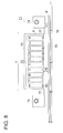
- Fig. 8 is, of the ink-jet printers shown in Fig. 1 - Fig.7 , an elevation view showing an ink-jet recording head and an irradiation member irradiating actinic radiation.
- Recording apparatus 71 is constituted of head carriage 72, ink-jet head 73, irradiation member 74, and platen section 75.
- platen section 75 is arranged under recording medium P.
- Platen section 75 functions to absorb ultraviolet radiation and also absorbs extra ultraviolet radiation having passed through recording medium P. Thereby, highly detailed images can be reproduced remarkably stably.
- Recording medium P is guided by guide member 76. Via action of a transportation member (unshown), recording medium P is transported from the front to the rear in Fag. 8.
- a head scanning member (unshown) allows head carriage 72 to reciprocate in direction Y shown in Fig. 8 , whereby scanning of ink-jet head 73 held by head carriage 72 is carried out.
- Head carriage 72 is arranged above recording medium P, and a plurality of recording heads 3, to be described later, corresponding to the number of colors used for image printing on recording medium P are housed so that ink ejection orifices 81 are arranged on the lower side. Head carriage 72 is arranged for recording apparatus 71 main body to freely enable reciprocation in direction Y in Fig. 8 . Via driving of the head scanning member, reciprocation is made in direction Y in Fig. 8 .
- Fig. 8 is drawn so that head carriage 72 houses ink-jet heads 73 for white (W), yellow (Y), magenta (M), cyan (C), black (K), light yellow (Ly), light magenta (Lm), light cyan (Lc), light black (Lk), and white (W).
- W white
- Y yellow
- M magenta
- C cyan
- K black
- K light yellow
- Ly light magenta
- Lc light cyan
- Lk light black
- W white
- the number of colors of recording heads 3 housed in head carriage 72 is appropriately determined.
- Ink-jet head 73 ejects an actinic radiation curable-type ink (for example, a UV ink) supplied by an ink supply member (unshown) onto recording medium P from ink ejection orifice 8 via action of a plurality of ejection members (unshown) provided inside.
- the UV ink ejected from ink-jet head 73 is composed of a colorant, a polymerizable monomer, and an initiator, and exhibits such a property that when irradiated with UV radiation, the initiator functions as a catalyst to perform curing of the monomer via cross-linking or polymerization reaction.
- Ink-jet head 73 moves from one end of recording medium P to the other end thereof in direction Y in Fig. 8 via driving of a head scanning member. During this scanning, the UV ink is ejected onto a specified area (being a depositable area) of recording medium P in the form of ink droplets and then the ink droplets are deposited onto this depositable area.
- a specified area being a depositable area
- the above scanning is carried out at an appropriate number of times to eject the UV ink toward one depositable area. Thereafter, recording medium P is appropriately transported from the front to the rear in Fig. 8 via a transporting member. While scanning using the head scanning member is carried out again, the UV ink is ejected onto a next depositable area adjacent to the above depositable area in the rearward direction in Fig. 8 .
- Irradiation member 74 is composed of a UV lamp which emits ultraviolet radiation having a specified wavelength range at stable exposure energy, and a filter which transmits ultraviolet radiation of a specified wavelength.
- applicable UV lamps include mercury lamps, metal halide lamps, excimer lasers, UV lasers, cold-cathode tubes, hot-cathode tubes, blacklights, and LEDs (light emitting diodes). Of these, preferable are band-shaped metal halide lamps, cold-cathode tubes, hot-cathode tubes, mercury lamps, or blacklights.
- Irradiation member 74 to cure a UV ink can be produced at low cost by using a blacklight as a radiation source therefor.
- Irradiation member 74 is nearly similar in size to the maximum capable of being set by recording apparatus (a UV ink-jet printer) 71 or to be larger in size than the depositable area among the depositable area on which the UV ink is ejected via one scanning of the ink-jet head 73 driven by the head scanning member.
- Irradiation member 74 is fix-mounted on both sides of head carriage 72 to become nearly parallel to recording medium P.
- ink-jet head 73 is entirely shielded from light. Further, it is effective that distance h1 between irradiation member 74 and recording medium P is set to be smaller than distance h2 between ink ejection orifice 81 of ink-jet head 73 and recording medium P (namely, h1 ⁇ h2); and also distance d between ink-jet head 73 and irradiation member 74 is set to be far (namely, d is set to be long). It is more preferable that bellows structure 77 is arranged between ink-jet head 73 and irradiation member 4.
- image formation can also be carried out by using a line head-type recording apparatus.
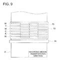
- Fig. 9 is a top view showing one example of a main part constitution of a line head-type ink-jet recording apparatus.
- the ink-jet recording apparatus shown in Fig. 9 is referred to as a line head system, and a plurality of ink-jet heads 73 of individual colors are fastened and arranged in head carriage 72 to cover the entire width of recording medium P.
- irradiation member 74 is arranged to cover the entire area of ink printing so that the entire width of recording medium P is similarly covered.
- a UV lamp used for irradiation member 74 a UV lamp similar to the one shown in Fig. 8 can be used.
- recording medium P is preferably warmed at 35 - 60 °C.
- a dispersion agent (PB822, produced by Ajinomoto Fine-Techno Co., Inc.) and each of the photopolymerizable compounds listed in Table 1 in a stainless steel beaker and then dissolved via stirring and mixing over 1 hour while heated on a hot plate of 65 °C. Subsequently, various pigments listed in Table 3 were added to the resulting solution and then the resulting mixture was placed in a poly bottle together with 200 g of zirconia beads of a diameter of 1 mm and tightly sealed, followed by dispersion treatment for 2 hours using a paint shaker.
- PB822 produced by Ajinomoto Fine-Techno Co., Inc.
- the zirconia beads were removed and various additives such as a photopolymerization initiator, a basic compound, and a surfactant were added in combinations as listed in Table 1.
- the resulting mixture was filtered by a 0.8 ⁇ m membrane filter to prevent printer clogging, whereby a curable composition ink was prepared.
- ink viscosity was allowed, to be 20 mPa ⁇ s - 30 mPa ⁇ s by adjusting the added amount of a compound having an oxetane ring and an epoxy compound to prepare inks 1 - 5.
- radically polymerizable ink 6 was produced using each of the materials listed in Table 2.
- Table 2 Ink No. Photopolymerizable Compound: Radically Polymerizable Monomer Monofunctional Radical Monomer *1 Pigment Remarks 6
- Pigments used for the individually colors are listed in Table 3.
- Table 3 Ink Type K C M Y Lk Lc Lm Ly Pigment Pigment Black 7 (#52, produced by Mitsubishi Chemical Corp.) Pigment Blue 15:4 (Cyanine Blue 4044, produced by Sanyo Color Works, Ltd.) Pigment Red 122 (a custom-ordered pigment, produced by Dainichiseika Color & Chemicals Mfg. Co., Ltd.) Pigment Yellow 150 (E4GN-GT CH20003, produced by Lanxess AG) * The pigment concentrations of the light color inks (designated as L) were allowed to be 1/5.
- Table 4 Printer Manifold Connection Portion Filter Chassis Frame Remarks A aluminum stainless steel stainless steel aluminum comparative B stainless steel brass stainless steel aluminum comparative C alumite-treated aluminum stainless steel stainless steel alumite-treated aluminum inventive D alumite-treated aluminum acid-treated stainless steel acid-treated stainless steel alumite-treated aluminum inventive E acid-treated stainless steel acid-treated brass acid-treated stainless steel alumite-treated aluminum inventive F resin-coated stainless steel resin-coated brass resin-coated stainless steel resin-coated aluminum inventive
- each metal surface was coated with tetrafluoroethylene at a thickness of 50 ⁇ m.
- the ink-jet head of each printer was filled with each ink and allowed to stand under an ambience of 50 °C for 3 days. Thereafter, multi-size dots of 2 - 20 pl were ejected with a nozzle number of 256 at a resolution of 720 x 720 dpi (dpi represents the number of dots per 2.54 cm). The ejection state of the inks of the individual colors was visually observed. Ejection stability was evaluated based on the following criteria.
- Tables 5 and 6 show that with regard to those wherein the metal of the liquid contact portion inside the head is subjected to passive treatment or insulating film treatment (resin coating treatment), no precipitates are noted and ejection performance is stable.
- inks employing a cationically polymerizable monomer are proved to be effective to a large extent.
- a yellow pigment dispersion was prepared based on the following method.
- C.I. Pigment Yellow 150 (E4GN-GT CH20015, produced by Lanxess AG) was added as a pigment to the resulting solution, followed by being placed in a glass bottle together with 200 parts of zirconia beads of a diameter of 0.3 mm and sealed. Dispersion was carried out using a paint shaker for 4 hours, followed by removal of the zirconia beads to prepare a yellow pigment dispersion.
- a magenta pigment dispersion was prepared in the same manner as in preparation of the above yellow pigment dispersion except that as the pigment, C.I. Pigment Yellow 150 was replaced with C.I. Pigment Red 122 (a custom-ordered pigment, produced by Dainichiseika Color & Chemicals Mfg. Co., Ltd.).
- a cyan pigment dispersion was prepared in the same manner as in preparation of the yellow pigment dispersion except that as the pigment, C.I. Pigment Yellow 150 was replaced with C.I. Pigment Cyan 15:4 (Cyanine Blue 4044, produced by Sanyo Color Works, Ltd.)
- a black pigment dispersion was prepared in the same manner as in preparation of the yellow pigment dispersion except that as the pigment, C.I. Pigment Yellow 150 was replaced with C.I. Pigment Black 7 (#52, produced by Mitsubishi Chemical Corp.).
- ink set 1A incorporating each of following yellow ink Y1, magenta ink M1, cyan ink C1, black ink K1, light yellow ink Ly1, light magenta ink Lm1, light cyan ink Lc1, and light black ink Lk1.
- Yellow ink Y1 was prepared using the above-prepared yellow pigment dispersion (containing the yellow pigment: 20% by mass; dispersion agent PB822: 8% by mass; and photopolymerizable compound OXT-221: 72% by mass) and the additives described below.
- the surface tension thereof was adjusted to be 27 mN/m at 25 °C, followed by degassing using a degassing module employing a hollow fiber membrane (SEPAREL PF-004D, produced by DIC Corp.) to prepare yellow ink Y1 of a pigment concentration of 3.0% by mass.
- a degassing module employing a hollow fiber membrane (SEPAREL PF-004D, produced by DIC Corp.) to prepare yellow ink Y1 of a pigment concentration of 3.0% by mass.
- Magenta ink M1, cyan ink C1, and black ink K1 of a pigment concentration of 3.0% by mass were prepared in the same manner as in preparation of above yellow ink Y1 except that the yellow pigment dispersion was replaced each with the magenta pigment dispersion, the cyan pigment dispersion, and the black pigment dispersion.
- Light yellow ink Ly1, light magenta ink Lm1, light cyan ink Lc1, and light black ink Lk1 were prepared in the same manner as in preparation of above yellow ink Y1, magenta ink M1, cyan ink C1, and black ink K1 except that each of the pigment concentrations was changed to 0.6% by mass.
- ink set 2A incorporating each of following yellow ink Y2, magenta ink M2, cyan ink C2, black ink K2, light yellow ink Ly2, light magenta ink Lm2, light cyan ink Lc2, and light black ink Lk2.
- Yellow ink Y2 was prepared using the above-prepared yellow pigment dispersion (containing the yellow pigment: 20% by mass; dispersion agent PB822: 8% by mass; and photopolymerizable compound OXT-221: 72% by mass) and the additives described below.
- the surface tension thereof was adjusted to be 27 mN/m at 25 °C, followed by degassing using a degassing module employing a hollow fiber membrane (SEPAREL PF-004D, produced by DIC Corp.) to prepare yellow ink Y2 of a pigment concentration of 3.0% by mass.
- a degassing module employing a hollow fiber membrane (SEPAREL PF-004D, produced by DIC Corp.) to prepare yellow ink Y2 of a pigment concentration of 3.0% by mass.
- Magenta ink M2, cyan ink C2, and black ink K2 of a pigment concentration of 3.0% by mass were prepared in the same manner as in preparation of above yellow ink Y2 except that the yellow pigment dispersion was replaced each with the magenta pigment dispersion, the cyan pigment dispersion, and the black pigment dispersion.
- Light yellow ink Ly2, light magenta ink Lm2, light cyan ink Lc2, and light black ink Lk2 were prepared in the same manner as in preparation of yellow ink Y2, magenta ink M2, cyan ink C2, and black ink K2 except that each of the pigment concentrations was changed to 0.6% by mass.
- Ink set 3A was prepared in the same manner as in preparation of above ink set 2A except that the type of each of the additives and the added amount thereof were changed as listed in Table 7.
- Table 7 Ink Set No. Cationically Polymerizable Monomer Photopolymerization Initiator Basic.
- the ink-jet printer having an ink supply line shown in Fig. 2b was used.
- Ink tank 101 and joints J1 - J4 were produced using SUS316 (stainless steel: chromium 18%, nickel 12%, and molybdenum 2.5%-).
- SUS316 stainless steel: chromium 18%, nickel 12%, and molybdenum 2.5%-.
- For ink supply paths 102A and 102B used was an ink-resistant TEFLON (a trademark) tube which was an insulating member having a thermal conductivity of 0.2 W/m ⁇ k and this tube was coated with a black polyolefin tube.
- an ink-jet head featuring the constitution shown in Fig.3 was used.
- Intermediate unit tank 105 the manifold section shown in Fig. 3 (manifolds 48a and 48b shown in Fig. 3 ), and the ink-jet head interior were also produced using SUS 316.
- Intermediate unit tank 105, the manifold section, and the ink-jet head were mounted with a heating member and heated from the outside at 50 °C.
- Ink-jet printers 2 - 25 were produced in the same manner as in production of ink-jet printer 1 except that the members constituting the intermediate unit tank, the manifold section (manifolds 48a and 48b shown in Fig. 3 ), and the ink contact portion of the ink-jet head were changed as listed in Table 8.
- Each ink-jet printer produced above was filled with an ink set from the ink tank to the ink-jet head containing a manifold based on the combination listed in Table 9 - Table 11, and then allowed to stand in this filled state under an ambience of 23 °C for 3 days. Thereafter, the presence or absence of precipitates in the intermediate unit tank, the manifold, and the ink-jet head was visually observed. Evaluation of precipitation resistance was conducted based on the following criteria.
- Each ink-jet printer produced above was filled with an ink set from the ink tank to the ink-jet head containing a manifold based on the combination listed in Table 9 - Table 11.
- the ink-jet head was constituted so that multi-size dots of 2 - 20 pl could be ejected with a nozzle number of 256 at a resolution of 720 x 720 dpi (dpi represents the number of dots per 2.54 cm).
- the intermediate unit tank and the ink-jet head were mounted with a heating member. While heating was applied from the outside at 50 °C, continuous ejection was carried out for 3 hours. Subsequently, the ejection state of each of the individual color inks was visually observed to determine the average ejection state thereof. Ejection stability was evaluated based on the following criteria.
- Table 9 Recording Method Ink Set Ink-jet Printer Precipitation Resistance Ejection Stability Remarks 1 1A 1 2 3 comparative 2 1A 2 4 1 comparative 3 1A 3 1 3 comparative 4 1A 4 1 3 comparative 5 1A 5 1 3 comparative 6 1A 6 3 3 inventive 7 1A 7 4 3 inventive 8 1A 8 4 3 inventive 9 1A 9 5 5 inventive 10 1A 10 5 5 inventive 11 1A 11 1 3 comparative 12 1A 12 1 3 comparative 13 1A 13 1 3 comparative 14 1A 14 4 3 invective 15 1A 15 5 5 inventive 16 1A 16 5 5 inventive 17 1A 17 3 1 comparative 18 1A 18 1 2 comparative 19 1A 19 1 3 comparative 20 1A 20 1 3 comparative 21 1A 21 3 3 inventive 22 1A 22 4 3 inventive 23 1A 23 4 4 inventive 24 1A 24 5 5 inventive 25 1A 25 5 5 incentive Table 10 Recording Method Ink Set Ink-jet Printer Precipitation Resistance Ejection Stability Remarks 1 1A 1 2 3 comparative 2 1A 2 4 1
- Table 9 - Table 11 clearly show that in any recording method using an ink-jet printer employing an ink-jet head which contains a manifold and is constituted of an alumite-treated aluminum member, excellent precipitation resistance and excellent ejection stability during continuous ejection while the manifold and the ink-jet head are heated are expressed, compared to the comparative examples.
Landscapes
- Chemical & Material Sciences (AREA)
- Engineering & Computer Science (AREA)
- Materials Engineering (AREA)
- Organic Chemistry (AREA)
- Metallurgy (AREA)
- Wood Science & Technology (AREA)
- Life Sciences & Earth Sciences (AREA)
- Chemical Kinetics & Catalysis (AREA)
- Electrochemistry (AREA)
- Manufacturing & Machinery (AREA)
- Mechanical Engineering (AREA)
- Ink Jet (AREA)
- Ink Jet Recording Methods And Recording Media Thereof (AREA)
- Particle Formation And Scattering Control In Inkjet Printers (AREA)
Abstract
Description
- The present invention relates to an ink-jet head used to eject an ink-jet ink containing a photopolymerizable compound, an ink-jet printer, and an ink-jet recording method using the same.
- Over recent years, due to simple and inexpensive production of images, an ink-jet recording system has been used in a wide variety of printing fields including specialty printing such as photograph, various types of printing, marking, and color filters. Generally, a water-based ink-jet ink containing water as a main solvent is recorded onto exclusive paper with ink absorbability serving as a recording medium. There have also been put into practical use ink-jet systems, other than such a water-based one, such as a phase-change ink-jet system utilizing wax ink which is solid at room temperature; a solvent-based ink-jet system utilizing ink mainly containing a quick-drying organic solvent; and an actinic radiation curable-type ink-jet system carrying out cross-linking via irradiation of actinic energy beams (radiation) such as ultraviolet radiation (UV light) after recording.
- Of these, over recent years, attention is being paid to the ultraviolet radiation curable-type ink-jet system in view of emission of a relatively low odor, quick-drying properties, and printability onto recording media with no ink absorbability, compared to the solvent-based ink-jet system. Accordingly, a wide variety of actinic radiation curable-type ink-jet technologies have been disclosed.
- Actinic radiation curable-type ink-jet inks employing radically polymerizable compounds represented by (meth)acrylates have been put into practical use. Due to adhesion to recording media, less odor, and less polymerization inhibition by oxygen, actinic radiation curable-type ink-jet inks employing cationically polymerizable compounds, as well as ink-jet printers utilizing the same have recently been proposed (for example, refer to
Patent Documents - In contrast, as to an ink-jet head, there is frequently used a metal such as stainless steel or aluminum as a material constituting an ink supply path in the head and a filter to remove foreign substances.
- In a water-based ink-jet head commonly used, a metal inside the head was often corroded by water present in an ink. Such corrosion often caused clogging by corroded materials in the ink-jet head, whereby, in severe cases, the ink-jet head itself was frequently disabled completely. Therefore, to prevent contact of the metal surface with water, a resin has been coated on the liquid contact portion of the metal (for example, refer to Patent Document 4).
- On the other hand, when ink ejection for recording is carried out using an ink containing a photopolymerizable compound from an ink-jet head constituted of the metallic material as described above, despite almost no corrosion of the metal constituting a liquid contact portion of the ink-jet head due to almost no presence of water in the ink, precipitates have become confirmed inside the ink-jet head with the elapsed time of ejection of the ink-jet ink. It has been found that these precipitates caused clogging of the ink supply path, and then reaching thereof to the nozzle section caused ejection failure.
- In general, precipitation with respect to an actinic radiation curable-type ink-jet ink is caused by leaked light of actinic radiation or pigment aggregation in some cases, and therefore various countermeasures against these phenomena have been taken so far. However, with regard to a cationically polymerizable ink, when a metallic material was used as a liquid contact member of an ink-jet printer, it has been found that undesirable electrochemical reaction occurred and thereby decomposed materials or polymerized materials of ink components were generated. When a metallic material is used as the liquid contact member of an ink-jet printer in this manner, unexpected ink polymerization reaction has been found to occur with long-term contact of a cationically polymerizable ink with the metallic material.
- Such a metallic material is commonly, for example, an electrically conductive material. For example, SUS, copper, or aluminum is employed as a conductive liquid contact member in an ink flow path of an ink-jet printer. Further, an example is known in which a conductive liquid contact member is employed for an ink-jet head of an ink-jet printer. It is thought that these electrically conductive members usually exhibit excellent durability to various inks such as a water-based ink-jet ink, a solvent-based ink-jet ink, an oil-based ink-jet ink, an ultraviolet radiation curable-type ink-jet ink, and a solid-based ink-jet ink; and also adversely affect such inks only to a small extent.
- It was found that when any of these electrically conductive members came into contact with a polymerizable, conductive ink, undesirable electrochemical reaction occurred, whereby decomposed materials or polymerized materials of ink components were generated in a flow path or an ink-jet head. Further, corrosion causes metal dissolution. Accordingly, when an ink containing a polymerizable compound is used, this electromotive force or metal dissolution triggers unexpected ink polymerization reaction in cases when the ink remains in contact with the interior of the flow path or ink-jet head over a long-term period. Especially, a cationically polymerizable actinic radiation curable-type ink-jet ink containing a photolytically acid generating agent such as an onium salt as an essential material tends to produce such a problem due to relatively high electrical conductivity of the ink.
- These reaction products are not redissolved in the ink. Therefore, deposition thereof in an ink-jet head, specifically in a nozzle peripheral portion causes a decrease in ejection straightness. In worst cases, unrecoverable nozzle clogging is caused.
- Patent Document 1: Unexamined Japanese Patent Application Publication No. (hereinafter also referred to as JP-A)
2005-290246 - Patent Document 2:
JP-A 2004-34543 - Patent Document 3:
JP-A 2005-238742 - Patent Document 4:
JP-A 2006-159619 - An object of the present invention is to provide, in an ink-jet head forming an image on a recording medium by ejecting an ink-jet ink containing at least a ecipitates in an ink contact portion and to carry out image recording with excellent ejection stability; an ink-jet printer; and an ink-jet recording method using the same.
- The above problems were able to be solved by the following constitution:
-
Item 1. In an ink-jet head used to form an image on a recording medium by ejecting an ink-jet ink containing at least a photopolymerizable compound from a nozzle, wherein a surface of a metal constituting a liquid contact member in contact with the ink-jet ink inside the ink-jet head is at least partially subjected to a passive treatment or an insulating film treatment. -
Item 2. The ink-jet head described initem 1 above, wherein the surface of the metal constituting the above liquid contact member in contact with an ink-jet ink is entirely subjected to a passive treatment or an insulating film treatment. -
Item 3. The ink-jet head described initem -
Item 4. The ink-jet head described in any one of items 1 - 3 above, wherein the liquid contact member is at least one selected from a manifold, a filter, a connection portion, and a chassis. -
Item 5. The ink-jet head described in any one of items 1 - 4 above, wherein the metal subjected to the passive treatment or the insulating film treatment is an alumite-treated aluminum member. - Item 6. The ink-jet head described in any one of items 1 - 4 above, wherein the metal subjected to the passive treatment or the insulating film treatment is an alumite-treated silicon-containing aluminum member.
- Item 7. The ink-jet head described in item 6 above, wherein the silicon content of the alumite-treated silicon-containing aluminum member is at least 10%.
-
Item 8. The ink-jet head described in any one of items 5 - 7 above, wherein the alumite-treated aluminum member and the alumite-treated silicon-containing aluminum member are each a member generating no bubbles and causing no color change of a solution when evaluated by the following evaluation method.
Evaluation method: a member to be evaluated (an alumite-treated aluminum member) is immersed in a test solution of 25°C prepared by dripping a few drops of a 1% by mass solution of phenolphthalein into a 0.2% by mass solution of NaCl; and subsequently, a voltage of 2.0 V is applied for 90 seconds between electrodes wherein the member to be evaluated and a stainless steel plate are arranged as a cathode and an anode respectively to visually evaluate bubble generation from the member to be evaluated and color change of the test solution. -
Item 9. The ink-jet head described in any one of items 5 - 8 above, wherein an alumite film thicknesses of the alumite-treated aluminum member and the alumite-treated silicon-containing aluminum member are each at least 9 µm. -
Item 10. An ink-jet printer forming an image on a recording medium by ejecting an ink-jet ink containing at least a photopolymerizable compound from a nozzle of an ink-jet head, wherein the ink-jet head is one described in any one of items 1 - 9 above. - Item 11. An ink-jet recording method comprising the steps of: a) ejecting an ink-jet ink onto a recording medium from a nozzle of an ink-jet head, and the ink-jet ink containing at least a photopolymerizable compound, and b) using the ink-jet printer described in
item 10 above to make an image, wherein a photopolymerizable compound contained in the ink-jet ink is a cationically polymerizable monomer which is an oxetane ring-containing compound or an epoxy compound. -
Item 12. The ink-jet recording method described in item 11 above, wherein the ink-jet ink contains a vinyl ether compound as a cationically polymerizable monomer. - Item 13. The ink-jet recording method described in
item 11 or 12 above, wherein the ink-jet ink contains a photolytically acid generating agent. - According to the present invention, there were able to be provided an ink-jet head and an ink-jet printer enabling to inhibit occurrence of precipitates in an ink contact portion and to carry out image recording with excellent ejection stability, as well as an ink-jet recording method using the same.
-
- [
Fig. 1 ] A view showing the entire constitution of an ink-jet printer used in the present invention. - [
Fig. 2 ] A schematic constitutional view showing one example of an ink supply path constitution in the ink-jet printer of the present invention. - [
Fig. 3 ] An exploded perspective view showing one example of an ink-jet head. - [
Fig. 4 ] A perspective view showing one manifold of two manifolds provided for the ink-jet head ofFig. 3 . - [
Fig. 5 ] A perspective view showing the other manifold of the two manifolds provided for the ink-jet head ofFig. 3 . - [
Fig. 6 ] A bottom view showing a chassis frame provided for the ink-jet head ofFig. 3 . - [
Fig. 7 ] A schematic view showing an outline of each flow path formed in the ink-jet printer ofFig. 3 . - [
Fig. 8 ] An elevation view showing an ink-jet head and an irradiation member irradiating actinic radiation in the ink-jet printer of the present invention. - [
Fig. 9 ] A top view showing one example of a main part constitution of a line head-system ink-jet recording apparatus. -
- 1 and 101: ink tanks
- 2, 73, and 104: ink-jet heads
- 3: actinic energy radiation source
- 4 and 103: carriages
- 5: carriage guide
- 8 and 102: ink supply paths
- 9: suction cap
- 10: maintenance unit
- 12: waste ink container
- 48a and 48b: manifolds
- 49: connection portion
- 51 and 107: filters
- 54: chassis
- 71: recording apparatus
- 72: head carriage
- 74: irradiation member
- 75: platen section
- 76: guide member
- 77: bellows structure
- 78: irradiation source
- 81: ink ejection orifice
- 106: intermediate tank anterior chamber
- 108: intermediate tank
- 110: filter box
- 111: filter adjacent portion
- J1 - J6: joints
- N: nozzle
- P: recording medium
- The best mode to carry out the present invention will now be detailed.
- In view of the above problems, the present inventor conducted diligent investigations, and then found that an ink-jet head enabling to inhibit generation of precipitates and exhibiting excellent ejection stability was able to be realized using an ink-jet head used to form an image on a recording medium by ejecting an ink-jet ink containing at least a photopolymerizable compound from a nozzle wherein the surface of a metal constituting a liquid contact member in contact with the ink-jet ink inside the ink-jet head is at least partially subjected to passive treatment or insulating film treatment. Thus, the present invention was completed.
- Namely, in an ink-jet head used for an ink-jet recording method employing an ink-jet ink containing a photopolymerizable compound (also referred to as an actinic radiation curable-type ink), various types of metals are used for an ink contact member inside the head. Therefore, it was found out that in an ink-jet ink containing a photopolymerizable compound, specifically in a cationically polymerizable curable-type ink-jet ink, a photopolymerization initiator contained in the ink-jet ink and such a metal reacted together, whereby a resulting reaction product served as a polymerization initiator to produce precipitates. As a result, it was found that the above problems were able to be solved by applying passive treatment or insulating film treatment to at least a part of the surface of a metal, preferably the entire surface of the metal constituting a liquid contact member in contact with the ink-jet ink inside the ink-jet head.
- The entire constitution of an ink-jet printer used for the ink-jet recording method of the present invention will now be described with reference to the accompanying drawings.
- An ink-jet printer used in the present invention is mainly constituted of an ink tank to store an ink-jet ink (hereinafter also referred to simply as an ink) containing a cationically polymerizable composition; an ink supply path to send an ink from the ink tank to an ink-jet head (hereinafter also referred to simply as a head); an ink-jet head to eject the ink supplied from the ink supply path onto a recording medium; and an actinic radiation irradiation source to cure ink droplets having been deposited on the recording medium.
-
Fig. 1 is a view showing the entire constitution of an ink-jet printer used in the present invention. - The
symbol 1 represents an ink tank to store and supply an ink containing a photopolymerizable compound. InFig. 1 , a constitution composed of yellow ink tank 1Y, magenta ink tank 1M, cyan ink tank 1C, and black ink tank 1K is illustrated as an example. Thesymbol 2 represents an ink-jet head having a nozzle to form an image by ejecting ink droplets onto a recording medium and incorporating yellow ink-jet head 2Y, magenta ink-jet head 2M, cyan ink-jet head 2C, and black ink-jet head 2K. Thesymbol 3 represents an actinic energy radiation source to irradiate UV radiation, that is, actinic energy radiation to an ink having been deposited on a recording medium. - The
symbol 4 represents a carriage. Carriage integrally holds ink-jet head 2 andenergy radiation source 3 and reciprocally moves via guiding ofcarriage guide 5 as shown by arrow WX to scan recording medium P, and then recording medium P is driven in the arrow WY direction to form an image on recording medium P. - A recording ink is supplied from
ink tank 1 to ink-jet head 2 throughink supply path 8. - The
symbol 10 represents a maintenance unit withsuction cap 9 to cap ink-jet head 2 for recovery treatment of ink-jet head 2. Thesymbol 12 represents a waste ink container to store waste ink, which receives and stores an ink having forcefully been ejected from ink-jet head 2 on flushing. -
Fig. 2 is a constitutional view showing one example of an ink supply path constitution in the ink-jet printer of the present invention. - In
Fig. 2a ,ink tank 101 is connected toink supply path 102 via joint J1, and further the end portion ofink supply path 102 is connected, via joint J2, to head 104 housed incarriage 103. Ink droplets are ejected onto a recording medium from nozzle N ofhead 104 based on image forming information and then actinic energy radiation is instantaneously irradiated to the deposited ink from actinic energy radiation source L to cure the ink. -
Fig. 2b shows one example in whichintermediate tank unit 105 havingfilter 107 built in is provided halfway inink supply path 102. The discharge outlet ofink tank 101 is connected toink supply path 102A via joint J1, which is connected tointermediate unit tank 105 via joint J3. An ink is sent to intermediate tankanterior chamber 106 from the joint J3 portion and then sent tointermediate tank 108 after removal of foreignsubstances using filter 107. Subsequently,intermediate tank 108 andink supply path 102B are connected together via joint J4.Ink supply path 102B is an ink supply line to supply the thus-filtered ink stored inintermediate tank 108 tohead 104. Herein, 109 shown inFig. 2b represents a filter adjacent portion adjacent to filter 107. -
Fig. 2c shows an example in which instead ofintermediate tank unit 105 inFig. 2b ,filter box 110 havingfilter 107 built in is provided. Infilter box 110, the ink inlet side is connected toink supply path 102A via joint J5 and the ink outlet side is connected toink supply path 102B via joint J6. Foreign substances in the ink are removed byfilter 107 arranged infilter box 110 to send the ink tohead 104. Herein, 111 shown inFig. 2c represents a filter adjacent portion adjacent to filter 107. - In
Fig. 2 described above, as a matter of convenience, only a line to supply an ink to a magenta ink-jet head is shown. As shown inFig. 1 , similar supply lines are also provided for a yellow ink-jet head, a cyan ink-jet head, and a black ink-jet head. Further, inFig. 2 , a constitution only for description is shown. Therefore, although unshown inFig. 2 , for example, a solenoid valve to control ink sending, a branch joint, and a liquid sending pump, as well as an ink-jet head control section are provided. - The ink-jet printer of the present invention is characterized in that for example, in the ink-jet printer or the ink supply line shown in
Fig. 1 orFig. 2 , at least a part of the surface of a metal, preferably the entire surface of the metal, constituting the liquid contact member in contact with an ink-jet ink inside an ink-jet head is subjected to passive treatment or insulating film treatment. Such a metal subjected to passive treatment or insulating film treatment is preferably composed of an alumite-treated aluminum member or an alumite-treated silicon-containing aluminum member. - Next, ink-
jet head 2 is described below with reference toFig. 3 - Fig. 6 . -
Fig. 3 is an exploded perspective view showing ink-jet head 2 of an embodiment of the present invention. As shown inFig. 3 , ink-jet head 2 of this embodiment is provided with 2 stacked ink-jet head tips (hereinafter referred to as "head tips") 41 to eject an ink.Head tips 41 are shaped into an elongate outline. A large number of ejection orifices are arranged in the bottom face (ejection face) thereof. Further,ink supply opening 43 of an almost rectangular shape is provided in the exterior side of each of 2 stackedhead tips 41. Andink supply opening 43 is communication-connected to the ejection orifices via an ink flow path (unshown). In a part of the ink flow path, a pressure chamber is formed, having a constitution to eject ink droplets from the ejection orifices based on pressure variation via action of piezoelectric devices. And inhead tip head drive boards 46 to send control signals from the control section to each piezoelectric device are each connected to the each piezoelectric device viaflexible wiring board 47. - On both sides of 2
head tips manifolds tips 41 are mounted.Fig. 4 andFig. 5 each are perspective views of 2manifolds Fig. 4 andFig. 5 ,connection portions ink supply opening 43 are provided in the face facinghead tips 41 inmanifolds Connection portions ink supply opening 43. In the interior thereof, firstconcave portions connection portions walls 492a and 492b are horizontally formed in plates to vertically divide firstconcave portions walls connection portions concave portions concave portions walls - Further, in the rear of
connection portions concave portions concave portions concave portions - In the front end portion of
manifolds injection openings concave portions concave portions injection openings communicative connection openings concave portions Injection openings communicative connection openings injection openings injection openings ink receiving sections injection openings communicative connection openings first bed sections communicative connection openings first side walls head tips 41 infirst bed sections ink receiving sections - In the rear end part of
manifolds piping arrangements concave portions jet head 2. Above cleaningpiping arrangements communicative connection openings concave portions communicative connection openings second bed sections communicative connection openings second side walls head tips 41 insecond bed sections - In the front end part of and the rear end part of
manifolds pieces head tips 41.Engaging piece 490a ofmanifold 48a, being one, and engagingpiece 490b ofmanifold 48b, being the other, are engaged together to mount 2manifolds tips 41. - In
connection portions manifolds filters Fig. 4 andFig. 5 ) are provided to cover firstconcave portions concave portions walls 492a and 492b and blockingwalls manifolds tips 41,filters ink supply opening 43 ofhead tips 41. Herein, there arespaces Fig. 7 ) betweenink supply opening 43 andfilters Spaces filters ink supply opening 43. - In the lower part of
head tips 41, an unshown holding plate is mounted in order to holdmanifolds head tips 41 so as for the ejection face to be exposed. - Further, in ink-
jet head 2, as shown inFig. 3 , provided is chassis (hereinafter also referred to as "chassis frame") 54 to which components of ink-jet head 2 such ashead tips 41,manifolds head drive boards 46, and the holding plate as described above are mounted and fastened.Chassis frame 54 is covered with an unshown cover. -
Fig. 6 is a bottom view ofchassis frame 54. In the lower end part ofchassis frame 54, twoside plates 55 are formed to cover both sides ofmanifolds chassis frame 54, there are provided, between 2side plates 55,first contact wall 56 in close contact with the front end portion ofink receiving sections manifolds second contact wall 57 in close contact with the front end portion offirst bed sections manifolds first contact wall 56. Gaps Hl are formed between both end portions offirst contact wall 56 andsecond contact wall 57 andside plate 55 so as only forfirst side walls manifolds first side walls first contact wall 56 andsecond contact wall 57. - Further, in the rear end portion of
chassis frame 54, there is provided, between 2side plates 55,third contact wall 58 in contact with the rear end portions ofsecond bed sections manifolds third contact wall 58 andside plates 55, gaps H2 are formed so as only forsecond side walls manifolds second side walls third contact wall 58. - Herein, a space formed by
first side walls ink receiving sections manifolds first contact wall 56 andsecond contact wall 57 is referred to as ink supply space I (refer toFig. 7 ), whereby ink supply space I is communication-connected toinjection openings manifolds chassis frame 54, inksupply flow path 59 is provided to supply an ink toinjection openings supply flow path 59 andinjection openings supply flow path 59 is provided in the front end portion ofchassis frame 54 and is communication-connected toink connection portion 60 of a cylindrical shape connected to ink supply pipe 6. - Further, a space formed by
first side walls first bed sections manifolds second contact wall 57 is referred to as first communicative connection space Sl (refer toFig. 7 ), whereby first communicative connection space Sl is communication-connected to firstcommunicative connection openings manifolds connection flow path 61 is provided inchassis frame 54 to communication-connect the air to firstcommunicative connection openings connection flow path 61 and firstcommunicative connection openings connection flow path 61 is provided in the vicinity ofink connection portion 60 and communication-connected to firstpump connection portion 62 of a cylindrical shape connected to a first pump (unshown) to negatively pressurize the interior ofmanifolds connection flow path 61, a conventionally known check valve (unshown) is provided to prevent the ink inside the flow path from flowing back to the manifold interior. - Still further, a space formed by
second side walls second bed sections manifolds third contact wall 58 is referred to as second communicative connection space S2 (refer toFig. 7 ), whereby second communicative connection space S2 is communication-connected to secondcommunicative connection openings manifolds connection flow path 63 is provided inchassis frame 54 to communication-connect the air to secondcommunicative connection openings connection flow path 63 and secondcommunicative connection openings connection flow path 63 is provided in the rear end portion ofmanifolds pump connection portion 64 of a cylindrical shape connected to a second pump (unshown) to negatively pressurize the interior ofmanifolds connection flow path 63, a conventionally known check valve (unshown) is provided to prevent the ink in the flow path from flowing back to the manifold interior. -
Fig. 7 is a schematic view showing an outline of each flow path formed in ink-jet head 2. - An ink is supplied from
ink tank 5 and then the ink flows into ink-jet head 2 via ink supply pipe 6 by initiating the ink supply pump. In ink-jet head 2, initially, the ink passes through inksupply flow path 59 and reaches ink supply space I, and then divergingly enters intoinjection openings manifolds manifolds concave portions filters spaces spaces head tips 41 fromink supply opening 43. Namely, the ink flow paths inmanifolds ink supply opening 43 ofhead tips 41 frominjection openings concave portions spaces connection flow path 61 is communication-connected to the upstream side offilters connection flow path 63 is communication-connected to the downstream side offilters - The ink-jet head of the present invention is characterized in that the surface of a metal constituting a liquid contact member in contact with an ink-jet ink inside an ink-jet head is at least partially subjected to passive treatment or insulating film treatment. An ink contact member a part of which is composed of a metal includes the manifold (48), the connection portion (49), the filter (51), and the chassis frame (54).
- Metal members constituting the ink-jet head of the present invention include metallic materials, which are also commonly applied to form structural objects. Specifically, there can be used iron, aluminum, zirconium, copper, nickel, tin, zinc, lead, silver, gold, alloys thereof, and alloys employing other metals. Of these, preferable are stainless steel, aluminum, zirconium, copper, and brass. Stainless steel and aluminum are more preferable from the viewpoint of processability, handling properties, and cost.
- As stainless steel, ferritic stainless steel and austenitic stainless steel are used. These stainless steels inherently have a Cr/Fe atomic ratio of about 0.7 - 1.2 on the surface thereof. In the present invention, those allowed to have at least 2.0 for this atomic ratio are used.
- Passive treatment referred to in the present invention is treatment for producing a state in which a metal losses its expected chemical reactivity. For example, as soon as iron is immersed in a concentrated nitric acid, the iron becomes hard to dissolve, whereby no copper is precipitated even when the iron is placed in a copper sulfate solution. In this case, the iron is said to become passive.
- Specific examples of passive treatment include acid treatment or acid generating treatment in which stainless steel is immersed in a concentrated nitric acid or a chromic acid solution; fluorinated passive treatment in which an oxide film on the surface of stainless steel is removed and then fluorine gas treatment is carried out at 265°C or lower; and Cr2O3 passive treatment employing chromic acid. Such acid treatment is desirably carried out using an acid aqueous solution enabling to remove stains, rust, and scale remaining on the stainless steel surface, preferably using a nitric acid solution mainly. Further, of course, any appropriate passive treatment other than the above passive treatments may be carried out.
- Passive treatment for aluminum includes alumite treatment and glass coating treatment. Alumite is a material in which aluminum is coated with an anticorrosive oxide film via anodization. The oxide film is mainly composed of Al2O3, depending on the treatment. And alumite treatment is a method in which aluminum is immersed in oxalic acid, sulfuric acid, or a chromic acid solution and then anodized to have an anticorrosive oxide film coated thereon, being used for building materials and containers. These are technologies to extremely enhance anticorrosive properties and insulating properties of the aluminum surface. In such alumite treatment, sealing treatment is preferably carried out further. This sealing treatment is treatment to seal porous portions. It is said that in hydration sealing of alumite, there is obtained pseudo-boehmite (γ-Al2O3·αH2O) (α = 1.4 - 2.0) of an acicular crystal shape intermediate between bayerite (γ-Al2O3·3H2O) and boehmite (γ-Al2O3·H2O).
- Glass coating treatment is treatment in which sodium silicate, referred to as liquid glass, is sintered on the surface of aluminum and used for reflectance enhancement of luminaires using a technology to dry a concentrated aqueous solution of an alkali silicate obtained by melting silicon dioxide and an alkali on the surface of aluminum.
- As an insulating film treatment, a resin coating treatment is preferably exemplified. As the resin coating treatment, for example, TEFLON (a registered trademark) coating and ceramic coating are preferably listed with no specific limitation. A polyimide (PI) resin, a polyamideimide (PAI) resin, and an epoxy resin may be used. TEFLON (a registered trademark) coating is specifically preferable.
- In the ink-jet head of the present invention, a metal subjected to a passive treatment or an insulating film treatment is preferably an alumite-treated aluminum member or an alumite-treated silicon-containing aluminum member. An alumite-treated aluminum member according to the present invention will now be described.
- Generally, aluminum produces a thin oxide film even on an untreated surface thereof by air oxidation, and thereby is highly resistant to corrosion, compared to iron, being, however, the metal exhibiting relatively low abrasion resistance and low environmental soundness. As a method to improve these properties, an anodization (alumite) treatment is carried out.
- The anodization (alumite) of aluminum referred to in the present invention is a method in which aluminum serving as an anode is electrolyzed to form an oxide film having a unique shape on the aluminum surface.
- An alumite film obtained via such anodization exhibits excellent adhesion properties and uniformity. The film thickness thereof is determined based on electrolysis conditions and duration. Accordingly, a desired film thickness can be obtained, compared to an electroplating method.
- In an anodization (alumite) treatment applied to an aluminum substrate, a substrate composed of aluminum or an aluminum alloy as an anode is generally electrolyzed in an acid bath such as chromic acid, sulfuric acid, boric acid, or sulfamic acid to form an oxide film on the substrate surface.
- Treatment conditions for this anodization are not simply specified, since optimum conditions depend on the electrolyte used. Generally, the following ranges are appropriate: the electrolyte concentration is 1 - 80% by mass; the liquid temperature is 5 - 70 °C; the current density is 0.5 60 A/dm2; the voltage is 1 - 100 V; and the electrolysis duration is 10 seconds -. 10 hours.
- Prior to the anodization treatment, an aluminum substrate is preferably subjected to a degreasing treatment via degreasing cleaning methods using various materials such as an acid, an alkali, an organic solvent, and a surfactant. Further, subsequently, the surface thereof is also preferably subjected to etching treatment using an alkali, an acid, or a fluoride.
- Various kinds of aluminum alloys can be used for a substrate. For example, used are alloys of a metal such as silicon, copper, manganese, magnesium, chromium, zinc, lead, bismuth, nickel, titanium, or iron with aluminum. In an aluminum substrate used in the present invention, the composition thereof is not specifically limited and those known in the art and commonly used can be employed.
- From the viewpoint of processing accuracy of a member, an aluminum alloy having a large content of silicon is more preferable. However, treatment duration for common alumite processing as described above may increase extremely or the surface may become nonuniform.
- In the present invention, one of the features is that an aluminum member is an alumite-treated silicon-containing aluminum member. Further, the silicon content is preferably at least 10%, specifically preferably at least 20%.
- When an aluminum alloy having such a large content of silicon is subjected to alumite treatment, special alumite processing is required as described in
JP-A 2005-113262 - In an alumite-treated aluminum member and an alumite-treated silicon-containing aluminum member according to the present invention, the alumite film thickness of the alumite-treated aluminum member and the alumite-treated silicon-containing aluminum member is preferably at least 9 µm.
- The thought that the alumite film thickness of an alumite-treated aluminum member and an alumite-treated silicon-containing aluminum member is at least 9 µm means that an alumite film having a thickness of at least 9 µm is formed on the entire ink contact surface of a member composed of alumite-treated aluminum and any area with no alumite film is produced. However, it is not meant that the alumite film in every area is formed with uniform film thickness in the entire area.
- In the present invention, whether or not an alumite film with a predetermined film thickness is formed on the ink contact surface can be confirmed based on a method specified by the present invention.
- Namely, an aluminum member as an object to be tested entirely subjected to the alumite treatment is immersed in a test solution of 25 °C prepared by dripping a few drops of a 1% by mass solution of phenolphthalein into a 0.2% by mass solution of NaCl. Subsequently, the alumite-treated aluminum member and a stainless steel plate are arranged as a cathode and an anode, respectively, and then a voltage of 2.0 V is applied for 90 seconds between the electrodes. In the meantime, the presence or absence of bubble generation from the surface of the alumite-treated aluminum member, or occurrence or no occurrence of color change of the test solution is visually observed. When neither bubble generation nor color change of the test solution is noted, it is determined that an alumite film is entirely formed at a film thickness of at least a predetermined one on this alumite-treated aluminum member. On the other hand, when bubble generation or color change (being changed to red) of the test solution is noted, it is indicated that an alumite film formed on the aluminum surface is nonuniform; namely an area of at most a film thickness specified by the present invention exists or an area, in which no alumite film is formed and the alumite substrate is exposed, exists; and then induced electrolysis generates electrolysis gas or formation of aluminum hydroxide shifts the test solution toward the alkali side.
- Next, an ink according to the present invention will now be described.
- An ink containing a photopolymerizable compound according to the present invention contains a cationically polymerizable composition or a radically polymerizable composition. In the present invention, an ink containing a cationically polymerizable composition is preferably employed.
- An ink containing a cationically polymerizable composition according to the present invention contains a cationically curable monomer (a cationically polymerizable compound) and a photopolymerization initiator. Such a cationically curable monomer (a cationically polymerizable compound) preferably contains at least one compound selected from compounds containing an oxetane ring and epoxy compounds, and more preferably contains a vinyl ether compound.
- A compound containing an oxetane ring according to the present invention will now be described.
- As a cationically polymerizable composition, an oxetane compound having at least one oxetane ring substituted at the 2-position represented by following Formula (14) in the molecule is preferably used.

- In Formula (14), R1 - R6 each represent a hydrogen atom or a substituent. Herein, at least one group represented by R3 -, R6 is a substituent. In Formula (14), the substituents represented by R1 - R6 represent, for example, a fluorine atom, an alkyl group of a carbon atom number of 1 - 6 (e.g., a methyl group, ethyl group, propyl group, or butyl group), a fluoroalkyl group of a carbon atom number of 1 - 6, an allyl group, an aryl group (e.g., a phenyl group or naphthyl group), a furyl group, or a thienyl group. These groups may further have a substituent.
- Further, of those represented by above Formula (14), compounds having any of the oxetane rings represented by following Formulas (15) - (18) are preferably used.


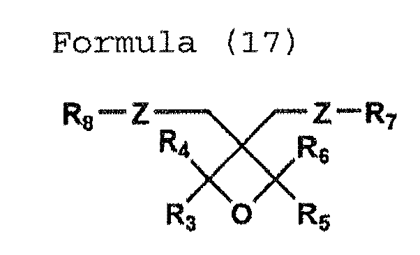

- In the formulas, R1 - R6 each represent a hydrogen atom or a substituent; R7 and R8 each represent a substituent; and Z's each are independent, representing an oxygen or sulfur atom, or a divalent hydrocarbon group which may contain an oxygen or sulfur atom in the main chain. The substituents represented by R1 - R6 in Formulas (15) - (18) are synonymous with the substituents represented by R1 - R6 in Formulas (14).
- In Formulas (15) - (18), the substituents represented by R7 and R8 represent an alkyl group of a carbon atom number of 1 - 6 (such as, a methyl group, ethyl group, propyl group, and butyl group), an alkenyl group of a carbon atom number of 1 - 6 (such as, a I-propeny group, 2-propenyl group, 2-methyl-1-propenyl group, 2-methyl-2-propenyl group, 1-butenyl group, 2-butenyl group, and 3-butenyl group), an aryl group (such as, a phenyl group and naphthyl group), an aralkyl group (such as, a benzyl group, fluorobenzyl group, and methoxybenzyl group), an acyl group of a carbon atom number of 1 - 6 (such as, a propylcarbonyl group, butylcarbonyl group, and pentylcarbonyl group), an alkoxycarbonyl group of a carbon atom number of 1 - 6 (such as, an ethoxycarbonyl group, propoxycarbonyl group, and butoxycarbonyl group), an alkylcarbamoyl group of a carbon atom number of 1 - 6 (such as, a propylcarbamoyl group and butylpentyl carbamoyl group), or an alkoxycarbamoyl group (such as, an ethoxycarbamoyl group).
- In Formulas (15) - (18), as an oxygen atom or a sulfur atom, or divalent hydrocarbon groups which may contain an oxygen or sulfur atom in the main chain represented by Z in Formulas (15) - (18) include an alkylene group (such as, an ethylene group, trimethylene group, tetramethylene group, propylene group, ethylethylene group, pentamethylene group, hexamethylene group, heptamethylene group, octamethylene group, nonamethylene group, and decamethylene group), an alkenylene group (such as, a vinylene group and propenylene group), and an alkynylene group (such as, an ethynylene group and 3-pentynylene group). Further, the carbon atoms of the above alkylene group, alkenylene group, and alkynylene group may be substituted with an oxygen atom or a sulfur atom.
- Of the above substituents, R1 is preferably a lower alkyl group (such as, a methyl group, ethyl group, and propyl group), and an ethyl group is specifically preferably used. Further, as R7 and R8, preferable is a propyl group, a butyl group, a phenyl group, or a benzyl group. Z is preferably a hydrocarbon group (such as, an alkylene group, alkenylene group, and alkynylene group) containing no oxygen or sulfur atom.
- Further, in the present invention, compounds having at least 2 oxetane rings in the molecule as represented by following Formulas (19) and (20) can be used.


and wherein R9 represents a linear or branched alkylene group of a carbon atom number of 1 - 12, a linear or branched poly(alkyleneoxy) group, or a divalent group selected from the group consisting of those represented by following Formulas (22), (23), and (24). - As one example of the branched alkylene group of a carbon atom number of 1 - 12, an alkylene group represented by following Formula (21) is preferably used.


- In an embodiment of a preferable partial structure of a compound having an oxetane ring used in the present invention, for example, R1 in above Formulas (19) and (20) is preferably a lower alkyl group (e.g., a methyl group, ethyl group, or propyl group). An ethyl group is specifically preferable. Further, R9 is preferably a hexamethylene group. Or, those having R14 as a hydrogen atom in Formula (23) are preferably used.
- In Formula (21), R10 is preferably an ethyl group. R12 and R13 each are preferably a methyl group and z is preferably a hydrocarbon group containing no oxygen or sulfur atom.
- Further, as one example of the preferred embodiments of a compound having an oxetane ring according to the present invention, a compound represented by following Formula (26) is cited.

- Specific examples of a compound having an oxetane ring substituted at the 2-position according to the present invention will now be listed as exemplified compounds 1 - 15 that by no means limit the scope of the resent invention.
- 1: trans-3-tert-Butyl-2-phenyloxetane
- 2: 3,3,4,4-Tetramethyl-2,2-diphenyloxetane
- 3: Di[3-ethyl(2-methoxy-3-oxetanyl)]methyl ether
- 4: 1,4-Bis(2,3,4,4-tetramethyl-3-ethyl-oxetanyl)butane
- 5: 1,4-Bis(3-methyl-3-ethyloxetanyl)butane
- 6: Di(3,4,4-trimethyl-3-ethyloxetanyl)methyl ether
- 7: 3-(2-Ethyl-hexyloxymethyl)-2,2,3,4-tetramethyloxetane
- 8: 2-(2-Ethyl-hexyloxy)-2,3,3,4,4-pentamethyl-oxetane
- 9: 4,4'-Bis[(2,4-dimethyl-3-ethyl-3-oxetanyl)methoxy]biphenyl
- 10: 1,7-Bis(2,3,3,4,4-pentamethyl-oxatanyl)heptane
- 11: Oxetanyl·silsesquioxane
- 12: 2-Methoxy-3,3-dimethyloxetane
- 13 2,2,3,3-Tetramethyloxetane
- 14: 2-(4-Methoxyphenyl)-3,3-dimethyloxetane
- 15: Di(2-(4-methoxyphenyl)-3-methyloxetane-3-yl) ether
- A compound having an oxetane ring substituted at the 2-position according to the present invention can be synthesized by referring to the literatures listed below.
- (1) Hu Xianming and Richard M. Kellogg, Synthesis, 533 - 538, May (1955)
- (2) A. O. Fitton, J. Hill, D. Ejane, and R. Miller, Synth., 12, 1140 (1987)
- (3) Toshiro Imai and Sinya Nishida, Can. J. Chem., Vol. 59, 2503 - 2509 (1981)
- (4) Nobujiro Shimizu, Shintaro Yamaoka, and Yuho Tsuno, Bull. Chem. Soc. Jpn., 56, 3853 - 3854 (1983)
- (5) Walter Fisher and Cyril A. Grob, Helv. Chim. Acta., 61, 2336 (1978)
- (6) Chem. Ber., 101, 1850 (1968)
- (7) "Heterocyclic Compounds with Three- and Four-membered Rings", Part Two, Chapter IX, Interscience Publishers, John Wiley & Sons, New York (1964)
- (8) Bull. Chem. Soc. Jpn., 61, 1653 (1988)
- (9) Pure Appl. Chem., A29 (10), 915 (1992)
- (10) Pure Appl. Chem., A30 (2 & amp;3), 189 (1993)
- (11)
JP-A 6-16804 - (12) German Patent No.
1,021,858 - The content of a compound having an oxetane ring substituted at least at the 2-position according to the present invention in a cationically polymerizable ink is preferably 1 - 97% by mass, more preferably 30 - 95% by mass.
- Further, these compounds having an oxetane ring substituted at least at the 2-position according to the present invention may be used individually or 2 types thereof of different structure may be combined. Optionally, combined use with a photopolymerizable monomer or a polymerizable monomer to be described later is possible. In such combination, the mixing ratio of a compound having an oxetane ring substituted at least at the 2-position is preferably adjusted to be 10 -98% by mass in a mixture, and the mixing ratio of an added photopolymerizable compound such as a photopolymerizable monomer or polymerizable monomer is preferably adjusted to be 2 - 90% by mass.
- In the present invention, the above oxetane compound having a substituent at the 2-position and a conventionally known oxetane compound can be used in combination. Of these, an oxetane compound having a substituent only at the 3-position can preferably be used in combination.
- Herein, as such an oxetane compound having a substituent only at the 3-position, there can be used those known in the art disclosed in
JP-A Nos. 2001-220526 2001-310397 - As the oxetane compound having a substituent only at the 3-position, a compound represented by following Formula (24) is cited.

- As one example of a compound having 2 oxetane rings, a compound represented by following Formula (28) is cited.

- In Formula (28), R1 represents the same group as in Formula (27); and R3 represents, for example, a linear or branched alkylene group such as an ethylene group, propylene group, or butylene group, a linear or branched poly(alkyleneoxy) group such as a poly(ethyleneoxy) group or poly(propyleneoxy) group, or a linear or branched unsaturated hydrocarbon group such as a propenylene group, methylpropenylene group, or butenylene group; or a carbonyl group, an alkylene group containing a carbonyl group, an alkylene group containing a carboxyl group, or an alkylene group containing a carbamoyl group.
- Further, as R3, a multivalent group selected from the groups represented by following Formulas (29), (30), and (31) can be cited.

- In Formula (29), R4 represents a hydrogen atom, an alkyl group of a carbon atom number of 1 - 4 such as a methyl group, ethyl group, propyl group, or butyl group, an alkoxy group of a carbon atom number of 1 - 4 such as a methoxy group, ethoxy group, propoxy group, or butoxy group, a halogen atom such as a chlorine atom or bromine atom, a nitro group, a cyano group, a mercapto group, a lower alkoxycarbonyl group, a carboxyl group, or a carbamoyl group.

- In Formula (30), R5 represents an oxygen atom, a sulfur atom, a methylene group, NH, SO, SO2, (CF3)2, or C(CH3)2.

- In Formula (31), R6 represents an alkyl group of a carbon atom number of 1 - 4 such as a methyl group, ethyl group, propyl group, or butyl group, or an aryl group; n represents an integer of 0 - 2000; and R7 represents an alkyl group of a carbon atom number of 1 - 4 such as a methyl group, ethyl group, propyl group, or butyl group, or an aryl group and further R7 can include a group selected from a group represented by following Formula (32).

- In Formula (32), R8 represents an alkyl group of a carbon atom number of 1 - 4 such as a methyl group, ethyl group, propyl group, or butyl group, or an aryl group; and m represents an integer of 0 - 100.
- As specific examples of a compound having 2 oxetane rings, the following compounds are listed.


-
Exemplified compound 1 is a compound wherein R1 is an ethyl group and R3 is a carboxyl group in above Formula (28). And exemplifiedcompound 2 is a compound wherein in Formula (28), R1 is an ethyl group and R3 is a group in which R6 and R7 are a methyl group in above Formula (31); and n is 1. - With regard to the compound having 2 oxetane rings, as a preferred example other than the above compounds, a compound represented by following Formula (33) is cited. In Formula (33), R1 is synonymous with R1 of above Formula (27).

- Further, as one example of a compound having 3 - 4 oxetane rings, a compound represented by following Formula (34) is cited.

- In Formula (34), R1 is synonymous with R1 of above Formula (27). R9 includes, for example, a branched alkylene group of a carbon atom number of 1 - 12 such as the groups represented by following A - C; a branched poly(alkyleneoxy) group such as the group represented by following D; and a branched polysiloxy group such as the group represented by following E. The designation j represents 3 or 4.


- In A, R10 represents a lower alkyl group such as a methyl group, ethyl group, or propyl group. And in D, p represents an integer of 1 - 10.
- As one example of a compound having 3 or 4 oxetane rings, exemplified
compound 3 is cited.
- Further, as an example of a compound having 1 - 4 oxetane rings other than the ones described above, a compound represented by following Formula (35) is cited.

- In Formula (35), R8 is synonymous with R8 of above Formula (32). R11 represents an alkyl group of a carbon atom number of 1 - 4 such as a methyl group, ethyl group, propyl group, or butyl group, or a trialkylsilyl group and r represents 1 - 4.
- Preferred specific examples of the oxetane compound of the present invention include exemplified
compounds 


- A production method for each of the oxetane ring-containing compound is not specifically limited and it is only necessary to employ any appropriate method conventionally known in the art. For example, there is usable an oxetane ring synthesis method from a diol disclosed by Pattison (D. B. Pattison, J. Am. Chem. Soc., 3455, 79 (1957)). Further, in addition to these, listed are compounds having 1 - 4 oxetane rings having relatively high molecular weight of a molecular weight of about 1000 - 5000. As specific examples of these compounds, following exemplified
compounds 

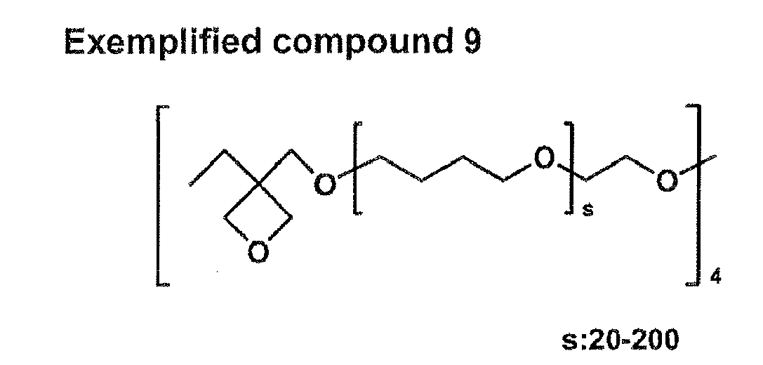
- As an epoxy compound according to the present invention, any of a monomer of a compound having an epoxy group and an oligomer thereof can be used. Specifically, a conventionally known aromatic epoxy compound, alicyclic epoxy compound, and aliphatic epoxy compound are listed. Incidentally, hereinafter, such epoxy compounds refer to monomers or oligomers thereof. As an oligomer in the present invention, a compound of lower molecular weight is preferable and an oligomer featuring a molecular weight of less than 1000 is preferable.
- Preferable aromatic epoxy compounds are di- or polyglycidyl ethers produced via reaction of polyphenols having at least one aromatic nucleus or alkylene oxide adducts thereof with epichlorohydrin. There are listed, for example, di- or polyglycidyl ethers of bisphenol A or alkylene oxide adducts thereof; di- or polyglycidyl ethers of hydrogenated bisphenol A or alkylene oxide adducts thereof; and novolac-type epoxy resins. Herein, the alkylene oxide includes ethylene oxide and propylene oxide.
- As alicyclic epoxy compounds, preferable are cyclohexene oxide- or cyclopentene oxide-containing compounds obtained by epoxidizing compounds having at least one cyclohexene ring or cyclopentene ring using an appropriate oxidant such as hydrogen peroxide or a peracid. Specific examples include compounds listed later.
- Preferable aliphatic epoxy compounds include di- or polyglycidyl ethers of aliphatic polyhydric alcohols or alkylene oxide adducts thereof. Typical examples thereof include diglycidyl ethers of alkylene glycols such as diglycidyl ethers of ethylene glycol, diglycidyl ethers of propylene glycol, or diglycidyl ethers of 1,6-hexanediol; polyglycidyl ethers of polyhydric alcohols such as di- or triglycidyl ethers of glycerin or alkylene oxide adducts thereof; and diglycidyl ethers of polyalkylene glycols such as diglycidyl ethers of polyethylene glycol or alkylene oxide adducts thereof or diglycidyl ethers of polypropylene glycol or alkylene oxide adducts thereof. Herein, the alkylene oxide includes ethylene oxide and propylene oxide.
- Further, in addition to these compounds, monoglycidyl ethers of aliphatic higher alcohols, being monomers having one oxirane ring in the molecule and monoglycidyl ethers of phenol or cresol can also be used. Of these epoxy compounds, in view of rapid curability, aromatic epoxy compounds and alicyclic epoxy compounds are preferable and the alicyclic epoxy compounds are specifically preferable. In the present invention, the above epoxy compounds may be used individually or at least 2 types thereof may be used in appropriate combination.
- Specific examples of such epoxy compounds preferably used in the present invention will now be listed.


- As the amount of an alicyclic epoxy compound added, the content thereof is preferably allowed to be 10 - 80% by mass. In the case of less than 10% by mass, curability markedly varies with curing ambiences (temperature and humidity), resulting in no practical use. In the case of more than 80% by mass, physical film properties after curing degrades, resulting in no practical use. In the present invention, one type of alicyclic epoxy compound may be used individually or at least 2 types may be used in appropriate combination.
- Further, production methods for these alicyclic epoxy compounds are not limited. Synthesis can be carried out with reference to literature documents such as Yuki Gosei II of ); The Chemistry of Heterocyclic Compounds-Small ; Yoshimura, Setsuchaku (Adhesion) Volume 29, No. 12, 32, 1985; Yoshimura, Setsuchaku (Adhesion) Volume 30, No. 5, 42, 1986; and Yoshimura, Setsuchaku (Adhesion) Volume 30, No. 7, 42, 1986, as well as patent gazettes such as
JP-A 11-100378 2906245 2926262 - A cationically polymerizable composition according to the present invention contains an epoxidized fatty acid eater or epoxidized fatty acid glyceride as an epoxy compound.
- Such an epoxidized fatty acid eater or epoxidized fatty acid glyceride is preferably used in combination in an oxetane compound/alicyclic epoxy compound system, from the viewpoint of safety and environment such as AMES, sensitizing properties, skin irritating properties, and odor. In addition, there can be overcome conventionally remaining problems such as wrinkle occurrence caused by curing contraction under curing ambiences (temperature and humidity) and failure in curability and ejection performance.
- As an epoxidized fatty acid ester or an epoxidized fatty acid glyceride usable for the present invention, those prepared by introducing an epoxy group into a fatty acid ester or a fatty acid glyceride are used with no specific limitation.
- Such an epoxidized fatty acid ester is one produced by epoxidizing an oleic acid ester. Methyl epoxystearate, butyl epoxystearate, or octyl epoxystearate is used. Further, an epoxidized fatty acid glyceride is one produced also by epoxidizing soy bean oil, linseed oil, or castor oil. Epoxidized boy bean oil, epoxidized linseed oil, or epoxidized castor oil is used.
- Vinyl ether compounds usable for the present invention include, for example, di- or trivinyl ether compounds such as ethylene glycol divinyl ether, diethylene glycol divinyl ether, triethylene glycol divinyl ether, propylene glycol divinyl ether, dipropylene glycol divinyl ether, butanediol divinyl ether, hexanediol divinyl ether, cyclohexanedimethanol divinyl ether, or trimethylolpropane trivinyl ether; and monovinyl ether compounds such as ethyl vinyl ether, butyl vinyl ether, i-butyl vinyl ether, octadecyl vinyl ether, cyclohexyl vinyl ether, hydroxybutyl vinyl ether, 2-ethylhexyl vinyl ether, cyclohexanedimethanol monovinyl ether, propyl vinyl ether, i-propyl vinyl ether, i-propenyl ether-O-propylene carbonate, dodecyl vinyl ether, diethylene glycol monovinyl ether, or octadecyl vinyl ether.
- Of these vinyl ether compounds, in view of curability, adhesion properties, and surface hardness, di- or trivinyl ether compounds are preferable. Divinyl ether compounds are specifically preferable. In the present invention, such vinyl ether compounds may be used individually or at least two types thereof may be used in combination.
- In a cationically polymerizable ink according to the present invention, an onium salt can be used as a cationic polymerization initiator (also referred to simply as a photopolymerization initiator). Such an onium salt includes a sulfonium salt, an oxonium salt, and an iodonium salt.
- As a sulfonium salt used as a cationic polymerization initiator in the present invention, sulfonium salt compounds represented by following Formulas [1] - [4] are preferable.
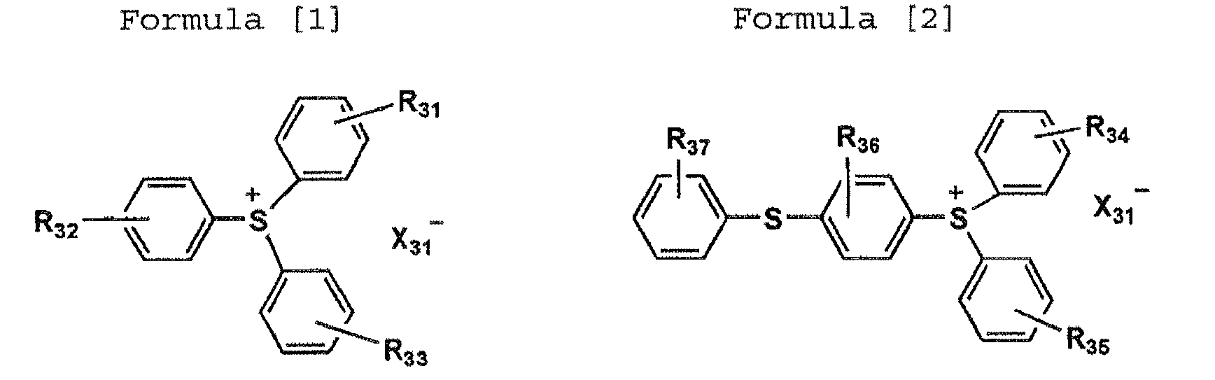


- In above Formulas [1] - [4], R31 - R47 each represent a hydrogen atom or a substituent. R31 - R33 do not represent a hydrogen atom simultaneously; R34 - R37 do not represent a hydrogen atom simultaneously; R38 - R41 do not represent a hydrogen atom simultaneously; and R42 - R47 do not represent a hydrogen atom simultaneously.
- The substituent represented by R31 - R47 preferably includes an alkyl group such as a methyl group, ethyl group, propyl group, isopropyl group, butyl group, isobutyl group, t-butyl group, pentyl group, or hexyl group; an alkoxy group such as a methoxy group, ethoxy group, propoxy group, butoxy group, hexyloxy group, decyloxy group, or dodecyloxy group; a carbonyl group such as an acetoxy group, propionyloxy group, decylcarbonyloxy group, dodecylcarbonyloxy group, methoxycarbonyl group, ethoxycarbonyl group, or benzoyloxy group; a phenylthio group; a halogen atom such as fluorine, chlorine, bromine, or iodine; a cyano group; a nitro group; and a hydroxyl group.
- X31 represents a non-nucleophilic anionic residue, including, for example, a halogen atom such as F, Cl, Br, or I, B(C6F5)4, R18COO, R19SO3, SbF6, AsF6, PF6, and BF4. Herein, R18 and R19 each represent an alkyl group such as a methyl group, ethyl group, propyl group, or butyl group; and an alkyl group or a phenyl group which can be substituted with a halogen atom such as fluorine, chlorine, bromine, or iodine, a nitro group, a cyano group, or an alkoxy group such as a methoxy group or ethoxy group. Of these, from the viewpoint of safety, B(C6F5)4 and PF6 are preferable.
- These compounds can readily be synthesized via well-known methods, similarly to the photolytically acid generating agents described in Bulletin of The Chemical Society of Japan, Vol. 71, No. 11, 1998 and Imaging Yo Yuki Zairyo (Organic Materials Used for Imaging Applications) edited by Yuki Electronics Zairyo Kenkyukai published by Bunshin Shuppan (1993).
- In the present invention, any of the sulfonium salts represented by above Formulas [1] - [4] is specifically preferably at least one type selected from the sulfonium salts represented by following Formulas [5] - [13] . X31 represents a non-nucleophilic anionic residue as described above.


- In the present invention, any of the sulfonium salts represented by above Formulas [1] - [4] is specifically preferably at least one type selected from the sulfonium salts represented by Formulas [5] - [13]. X represents a non-nucleophilic anionic residue as described above.
- Exemplified compounds, including iodonium salts, include the following compounds in addition to compounds in which X = PF6 in Formulas [5] - [13].


- The cationically polymerizable composition of the present invention preferably contains an onium salt at 1% by mass - less than 5% by mass as a photopolymerization initiator.
- An ink containing a radically polymerizable composition according to the present invention contains a radically curable monomer (a radically polymerizable monomer) and a photoradical polymerization initiator as a radically polymerizable composition (an actinic radiation curable composition or a photopolymerizable compound).
- A radically polymerizable monomer according to the present invention is a compound having a radically polymerizable ethylenically-unsaturated bond. Any compound having at least one radically polymerizable ethylenically-unsaturated bond in the molecule may be usable, including a chemical form such as a monomer, oligomer, and polymer. Such a radically polymerizable monomer may be used individually, or combined use of at least 2 types at an appropriate ratio is applicable to enhance the targeted characteristics.
- Examples of the compound having a radically polymerizable ethylenically-unsaturated bond includes unsaturated acids such as acrylic acid, methacrylic acid, itaconic acid, crotonic acid, isocrotonic acid, or maleic acid; salts, esters, urethanes, amides, and anhydrides thereof; acrylonitrile; and styrene, as well as various types of radically polymerizable compounds such as unsaturated polyesters, unsaturated polyethers, unsaturated polyamides, and unsaturated urethanes. Specifically, there are listed acrylic acid derivatives such as 2-ethylhexyl acrylate, 2-hydroxyethyl acrylate, butoxyethyl acrylate, carbitol acrylate, cyclohexyl acrylate, tetrahydrofurfuryl acrylate, benzyl acrylate, bis(4-acryloxypolyethaxyphenyl)prapane, neopentylglycol diacrylate, 1,6-hexanediol diacrylate, ethylene glycol diacrylate, diethylene glycol diacrylate, triethylene glycol diacrylate, tetraethylene glycol diacrylate, polyethylene glycol diacrylate, polypropylene glycol diacrylate, pentaerythritol triacrylate, pentaerythritol tetraacrylate, dipentaerythritol tetraacrylate, trimethylolpropane triacrylate, tetramethylolmethane tetraacrylate, oligoester acrylate, N-methylol acrylamide, diacetone acrylamide, or epoxy acrylate; and methacrylic acid derivatives such as methyl methacrylate, n-butyl methacrylate, 2-ethylhexyl methacrylate, lauryl methacrylate, allyl methacrylate, glycidyl methacrylate, benzyl methacrylate, dimethylaminomethyl methacrylate, 1,6-hexanediol dimethacrylate, ethylene glycol dimethacrylate, triethylene glycol dimethacrylate, polyethylene glycol dimethacrylate, polypropylene glycol dimethacrylate, trimethylolethane trimethacrylate, trimethylolpropane trimethacrylate, or 2,2-bis(4-methacryloxypolyethoxyphenyl)propane, as well as allyl compound derivatives such as allyl glycidyl ether, diallyl phthalate, or triallyl trimellitate. Further, there are usable radically polymerizable and cross-linkable monomers, oligomers, and polymers commercially available or known in the art described, specifically, in "Kakyozai Handbook (Handbook of Crosslinking Agents)," edited by Shinzo Yamashita (1981, Taisei Sha); "UV-EB Kohka Handbook (Genryo Hen)(UV·EB Curing Handbook (Raw Materials Part)," edited by Kiyoshi Kato (1985, Kohbunshi Kankoh Kai); "UV-EB Kohka Gijutsu no Ohyoh to Shijoh (Application and Market of UV·EB Curing Technology)", edited by Rad Tech Japan, page 79 (1989, CMC); and Eiichiroh Takiyama, "Polyester Jushi Handbook (Handbook of Polyester Resins)" (1988, Nikkan Kogyo Shimbun Ltd.). The amount of any of the above radically polymerizable compounds added is preferably 1 - 97% by mass, more preferably 30 - 95% by mass.
- As radical polymerization initiators, there are listed triazine derivatives described in Examined Japanese Patent Application Publication (hereinafter referred to as JP-B) Nos.
59-1281 61-9621 JP-A 60-60104 JP-A Nos. 59-1504 61-243807 JP-B Nos. 43-23684 44-6413 44-6413 47-1604 U.S. Patent No. 3,567,453 specification; organic azide compounds described inU.S. Patent Nos. 2,848,328 ,2,852,379 , and2,940,853 specifications; ortho-quinonediazides described inJP-B Nos. 36-22062 37-13109 38-18015 45-9610 JP-B 55-39162 JP-A 59-14023 JP-A 59-142205 JP-A 1-54440 109,851 126,712 JP-A Nos. 4-213861 4-255347 JP-A 61-151197 JP-A 2-182701 JP-A 3-209477 JP-A 59-107344 - An ink containing a photopolymerizable compound according to the present invention preferably contains a pigment as a colorant. Pigments preferably used in the present invention will now be listed:
- C.I.
Pigment Yellow - C.I. Pigment Orange 16, 36, and 38
- C.I.
Pigment Red 5, 22, 38, 48:1, 48:2, 48:4, 49:1, 53:1, 57:1, 63:1, 101, 122, 144, 146, 177, and 185 - C.I. Pigment Violet 19 and 23
- C.I. Pigment Blue 15:1, 15:3, 15:4, 18, 60, 27, and 29
- C.I. Pigment Green 7 and 36
- C.I. Pigment White 6, 18, and 21
- C. I. Pigment Black 7
- To disperse the above pigments, employable are various methods such as a ball mill, a sand mill, an atriter, a roll mill, an agitator, a Henschel mixer, a colloid mill, an ultrasonic homogenizer, a pearl mill, a wet-type jet mill, or a paint shaker. As a dispersion medium, photopolymerizable compounds and of these, monomers having the lowest viscosity are preferably selected in view of dispersion adaptability.
- In pigment dispersion, the average particle diameter of pigment particles is preferably 0.08 - 0.5 µm. To realize the maximum particle diameter at 0.3 - 10 µm, preferably 0.3 - 3 µm, a pigment, a dispersion agent, and a dispersion medium are appropriately selected and also dispersion and filtration conditions are appropriately set. This particle diameter control makes it possible to inhibit head nozzle clogging and to maintain ink storage stability, ink transparency, and curing sensitivity.
- In an actinic radiation curable-type ink according to the present invention, the concentration of a colorant is preferably 1% by mass - 10% by mass based on the entire ink amount.
- As a pigment dispersion agent, those having a basic anchor portion are preferably used. Further, polymer dispersion agents having a comb-like structure are more preferably used.
- Specific examples of such a pigment dispersion agent usable for the present invention include SOLSPERSE 9000, 17000, 18000, 19000, 20000, 24000SC, 24000GR, 28000, and 32000 (produced by Avecia Co.); AJISPER PB821 and PB822 (produced by Ajinomoto-Fine-Techno Co., Inc.); PLAAD ED214 and ED251 and DISPARLON DA-325 and DA-234 (produced by Kusumoto Chemicals Ltd.); and EFKA-5207, 5244, 6220, and 6225 (produced by EFKA Co.). Further, a pigment derivative (a synergist) can be used together with a pigment dispersion agent. Specific examples of such a pigment derivative include SOLSPERSE 5000, 12000, and 22000 (produced by Avecia Co.) and EFKA-6746 and EFKA-6750 (produced by EFKA Co.).
- An ink-jet ink according to the present invention preferably employs an actinic radiation curable-type composition and its viscosity is preferably in the range of 10 mPas - less than 50 mPas at 25 °C. It is preferable that the viscosity be at least 10 mPas to produce the effects of the present invention, and be less than 50 mPas from the viewpoint of ejection performance.
- As a recording medium used for image formation using the ink-jet printer of the present invention, a wide variety of recording media are usable. From the viewpoint of sufficiently exerting the characteristics of an actinic radiation curable-type ink according to the present invention, recording media practically having no ink absorbability are preferable. There can be used various non-absorptive plastics and films thereof employed for so-called soft packaging, in addition to common non-coated paper and coated paper. Examples of such various plastic films include polyethylene terephthalate (PET) film, oriented polystyrene (OPS) film, oriented polypropylene (OPP) film, oriented nylon (ONy) film, polyvinyl chloride (PVC) film, polyethylene (PE) film, and triacetyl acetate (TAC) film. As other plastics, polycarbonate, acrylic resins, ABS, polyacetal, polyvinyl alcohol (PVA), and rubber are usable. Metals and glass are also applicable. Of these recording media, when an image is formed specifically on a thermoshrinkable PET film, OPS film, OPP film, ONy film, or PVC film, the constitution of the present invention can be effective. These substrates tend to cause film curling and deformation due to curing contraction of the ink and heat generated during curing reaction, and also the ink film is difficult to conform to substrate contraction.
- Surface energies of these various types of plastic films each differ significantly. Consequently, there has been noted such a problem that the dot diameter after ink deposition varies, depending on the recording medium. However, according to the ink of the present invention, it is possible to form excellent highly detailed images on a wide variety of recording media exhibiting a surface energy of 35 - 60 mN/m, including OPP film and OPS film exhibiting low surface energy and PET exhibiting relatively high surface energy.
- In the present invention, from the viewpoint of recording medium cost such as packaging expense and production cost, print production efficiency, and suitability for various print sizes, it is advantageous to use long-length (web) recording media.
- An image forming method via the ink-jet recording method of the present invention will now be described.
- In an image forming method according to the present invention, preferable is a method wherein the ink described above is ejected and recorded on a recording medium via an ink-jet recording method and then cured via irradiation of actinic radiation such as ultraviolet radiation.
- In the present invention, after deposition of an ink on a recording medium and curing via irradiation of actinic radiation, the total ink film thickness is preferably 2 - 25 µm. In actinic radiation curable-type ink-jet recording in the screen printing field, at present, the total ink film thickness exceeds 25 µm. In the soft packaging printing field in which thin plastic materials are frequently used as recording media, in addition to the above-mentioned problems such as curling and wrinkling of a recording medium, there are also produced such problems that stiffness and feel of quality of the printed matter as a whole vary. Therefore, ink ejection which results in an excessively thick film is not preferable.
- Herein, the term "total ink film thickness" refers to the maximum value of ink film thickness of an image recorded on a recording medium. The meaning of the above total ink film thickness is the same as in cases in which recording is conducted via a single color ink-jet recording method, as well as a 2-color superimposing (secondary color), 3-color superimposing, or 4-color superimposing (white ink base) ink-jet recording method.
- To ensure ejection stability, with regard to ink ejection conditions, it is preferable to heat an ink-jet head and an ink at 35 - 100 °C for ejection. An actinic radiation curable-type ink results in a wide variation of viscosity due to the change of temperature. Viscosity variation directly affects the size of droplets and the rate of droplet ejection significantly, resulting in degraded image quality. Accordingly, it is necessary to raise ink temperature and maintain the resulting temperature at a constant value. The control width of the ink temperature falls within a specified temperature of ±5 °C, preferably within a specified temperature of ±2 °C, more preferably ±1 °C. Further, in the present invention, the droplet amount ejected from each nozzle is preferably 2 - 15 pl.
- In the image forming method of the present invention, with regard to actinic radiation irradiation conditions, actinic radiation is irradiated preferably 0.001 second - 1.0 second after ink deposition, more preferably 0.001 second - 0.5 second thereafter. In order to form highly detailed images, it is specifically critical that irradiation timing is as early as possible.
- In the ink-jet recording method of the present invention, radiation irradiation is carried out after deposition of an ink composition onto a recording medium. Radiation irradiation may be visible light irradiation or ultraviolet irradiation. Especially, ultraviolet irradiation is preferable. In ultraviolet irradiation, the amount of ultraviolet irradiation is at least 100 mJ/cm2, preferably at least 500 mJ/cm2, being at most 10,000 mJ/cm2, preferably at most 5,000 mJ/cm2. With the amount of ultraviolet irradiation falling within such a range, adequate curing reaction can be performed, and also it is advantageous that discoloring of a colorant via ultraviolet irradiation is prevented. For ultraviolet irradiation, there are listed lamps such as a metal halide lamp, a xenon lamp, a carbon arc lamp, a chemical lamp, a low-pressure mercury lamp, or a high-pressure mercury lamp. For example, commercially available lamps such as an H lamp, a D lamp, or a V lamp (produced by Fusion System Co.) can be used for such irradiation.
- A metal halide lamp has a continuous spectrum, compared to a high-pressure mercury lamp (main wavelength: 365 nm), and exhibits enhanced emission efficiency in the range of 200 - 450 nm being abundant in the long wavelength range. Accordingly, the metal halide lamp is suitable when using a pigment as in the actinic radiation curable-type composition of the present invention.
- As an irradiation method of actinic radiation radiation, its basic method is disclosed in
JP-A 60-132767 U.S. Patent No. 6,145,979 specification discloses, as irradiation methods, an optical fiber method and a method wherein a collimated light source is directed to a mirror surface placed on the side of a head unit and then UV radiation is irradiated onto a recording section. In the present invention, any of these irradiation methods can be used. - Further, one of the preferred embodiments is also a method wherein irradiation of actinic radiation is divided into 2 steps: initially, actinic radiation is irradiated via the above method 0.001 - 2.0 seconds after ink deposition; and then actinic radiation is further irradiated after completion of total printing. By dividing actinic radiation irradiation into 2 steps, recording medium contraction generated during ink curing can be prevented further.
- Conventionally, in a UV ink-jet system, it has been common that a high illuminance radiation source, whose total power consumption exceeds 1 kW·hr, is used to inhibit dot spreading and bleeding after ink deposition. However, use of such a radiation source have caused an excessively large magnitude of recording medium contraction specifically in shrink label printing, resulting in no practical use at present.
- In the present invention, actinic radiation having a maximum illuminance at a wavelength range of 254 nm is preferably used. Thereby, even when a radiation source having a total power consumption of at least 1 kW·hr is used, highly detailed images can be formed and recording medium contraction can fall within the practically allowable level.
- Next, an image forming method using the ink-jet printer of the present invention, the constitution of which has been detailed above, will now be described with reference to drawings.
-
Fig. 8 is, of the ink-jet printers shown inFig. 1 - Fig.7 , an elevation view showing an ink-jet recording head and an irradiation member irradiating actinic radiation. -
Recording apparatus 71 is constituted ofhead carriage 72, ink-jet head 73,irradiation member 74, andplaten section 75. Inrecording apparatus 71,platen section 75 is arranged under recording mediumP. Platen section 75 functions to absorb ultraviolet radiation and also absorbs extra ultraviolet radiation having passed through recording medium P. Thereby, highly detailed images can be reproduced remarkably stably. - Recording medium P is guided by
guide member 76. Via action of a transportation member (unshown), recording medium P is transported from the front to the rear in Fag. 8. A head scanning member (unshown) allowshead carriage 72 to reciprocate in direction Y shown inFig. 8 , whereby scanning of ink-jet head 73 held byhead carriage 72 is carried out. -
Head carriage 72 is arranged above recording medium P, and a plurality of recording heads 3, to be described later, corresponding to the number of colors used for image printing on recording medium P are housed so thatink ejection orifices 81 are arranged on the lower side.Head carriage 72 is arranged forrecording apparatus 71 main body to freely enable reciprocation in direction Y inFig. 8 . Via driving of the head scanning member, reciprocation is made in direction Y inFig. 8 . - Herein,
Fig. 8 is drawn so thathead carriage 72 houses ink-jet heads 73 for white (W), yellow (Y), magenta (M), cyan (C), black (K), light yellow (Ly), light magenta (Lm), light cyan (Lc), light black (Lk), and white (W). In practice, the number of colors of recording heads 3 housed inhead carriage 72 is appropriately determined. - Ink-
jet head 73 ejects an actinic radiation curable-type ink (for example, a UV ink) supplied by an ink supply member (unshown) onto recording medium P fromink ejection orifice 8 via action of a plurality of ejection members (unshown) provided inside. The UV ink ejected from ink-jet head 73 is composed of a colorant, a polymerizable monomer, and an initiator, and exhibits such a property that when irradiated with UV radiation, the initiator functions as a catalyst to perform curing of the monomer via cross-linking or polymerization reaction. - Ink-
jet head 73 moves from one end of recording medium P to the other end thereof in direction Y inFig. 8 via driving of a head scanning member. During this scanning, the UV ink is ejected onto a specified area (being a depositable area) of recording medium P in the form of ink droplets and then the ink droplets are deposited onto this depositable area. - The above scanning is carried out at an appropriate number of times to eject the UV ink toward one depositable area. Thereafter, recording medium P is appropriately transported from the front to the rear in
Fig. 8 via a transporting member. While scanning using the head scanning member is carried out again, the UV ink is ejected onto a next depositable area adjacent to the above depositable area in the rearward direction inFig. 8 . - The above operation is repeated. And by ejecting the UV ink from ink-
jet head 73 under synchronization with the head scanning member and the transporting member, an image is formed on recording medium P. -
Irradiation member 74 is composed of a UV lamp which emits ultraviolet radiation having a specified wavelength range at stable exposure energy, and a filter which transmits ultraviolet radiation of a specified wavelength. Herein, applicable UV lamps include mercury lamps, metal halide lamps, excimer lasers, UV lasers, cold-cathode tubes, hot-cathode tubes, blacklights, and LEDs (light emitting diodes). Of these, preferable are band-shaped metal halide lamps, cold-cathode tubes, hot-cathode tubes, mercury lamps, or blacklights. Especially, there are preferable low-pressure mercury lamps, hot-cathode tubes, cold-cathode tubes, and bactericidal lamps emitting ultraviolet radiation of a wavelength of 254 nm in view of efficiently carrying out bleeding prevention and dot diameter control.Irradiation member 74 to cure a UV ink can be produced at low cost by using a blacklight as a radiation source therefor. -
Irradiation member 74 is nearly similar in size to the maximum capable of being set by recording apparatus (a UV ink-jet printer) 71 or to be larger in size than the depositable area among the depositable area on which the UV ink is ejected via one scanning of the ink-jet head 73 driven by the head scanning member. -
Irradiation member 74 is fix-mounted on both sides ofhead carriage 72 to become nearly parallel to recording medium P. - As described above, as a method to regulate illuminance of the ink ejection section, of course, ink-
jet head 73 is entirely shielded from light. Further, it is effective that distance h1 betweenirradiation member 74 and recording medium P is set to be smaller than distance h2 betweenink ejection orifice 81 of ink-jet head 73 and recording medium P (namely, h1 < h2); and also distance d between ink-jet head 73 andirradiation member 74 is set to be far (namely, d is set to be long). It is more preferable that bellowsstructure 77 is arranged between ink-jet head 73 andirradiation member 4. - Herein, it is possible to appropriately change the wavelength of UV radiation irradiated by
irradiation member 74 by replacing a UV lamp or a filter provided forirradiation member 74. - With regard to the ink-jet printer of the present invention, image formation can also be carried out by using a line head-type recording apparatus.
-
Fig. 9 is a top view showing one example of a main part constitution of a line head-type ink-jet recording apparatus. The ink-jet recording apparatus shown inFig. 9 is referred to as a line head system, and a plurality of ink-jet heads 73 of individual colors are fastened and arranged inhead carriage 72 to cover the entire width of recording medium P. - On the other hand, on the downstream side of
head carriage 72,irradiation member 74 is arranged to cover the entire area of ink printing so that the entire width of recording medium P is similarly covered. As a UV lamp used forirradiation member 74, a UV lamp similar to the one shown inFig. 8 can be used. - In this line head system,
head carriage 72 andirradiation member 74 are fastened and only recording medium P is transported to carry out image formation via ink ejection and curing. Incidentally, in the present invention, recording medium P is preferably warmed at 35 - 60 °C. - The present invention will now specifically be described with reference to examples that by no means limit the scope of the present invention. Herein, the designation "part" or "%" in the examples represents "part by mass" or "% by mass" unless otherwise specified.
- There were placed 1 part by mass of a dispersion agent (PB822, produced by Ajinomoto Fine-Techno Co., Inc.) and each of the photopolymerizable compounds listed in Table 1 in a stainless steel beaker and then dissolved via stirring and mixing over 1 hour while heated on a hot plate of 65 °C. Subsequently, various pigments listed in Table 3 were added to the resulting solution and then the resulting mixture was placed in a poly bottle together with 200 g of zirconia beads of a diameter of 1 mm and tightly sealed, followed by dispersion treatment for 2 hours using a paint shaker. Subsequently, the zirconia beads were removed and various additives such as a photopolymerization initiator, a basic compound, and a surfactant were added in combinations as listed in Table 1. The resulting mixture was filtered by a 0.8 µm membrane filter to prevent printer clogging, whereby a curable composition ink was prepared. Incidentally, ink viscosity was allowed, to be 20 mPa·s - 30 mPa·s by adjusting the added amount of a compound having an oxetane ring and an epoxy compound to prepare inks 1 - 5.


- Further, radically polymerizable ink 6 was produced using each of the materials listed in Table 2.
Table 2 Ink No. Photopolymerizable Compound: Radically Polymerizable Monomer Monofunctional Radical Monomer *1 Pigment Remarks 6 Compound tetraethylene glycol diacrylate ε-caprolactam-modified dipentaerythritol hexaacrylate ethylene oxide-added trimethylolpropane triacrylate phenoxyethyl methacrylate IRUGACURE 184 each color pigment Inv. Added Amount (% by mass) 30 27 20 10 10 3 *1 Photopolymerization Initiator, Inv.: present invention - Pigments used for the individually colors are listed in Table 3.
Table 3 Ink Type K C M Y Lk Lc Lm Ly Pigment Pigment Black 7 (#52, produced by Mitsubishi Chemical Corp.) Pigment Blue 15:4 (Cyanine Blue 4044, produced by Sanyo Color Works, Ltd.) Pigment Red 122 (a custom-ordered pigment, produced by Dainichiseika Color & Chemicals Mfg. Co., Ltd.) Pigment Yellow 150 (E4GN-GT CH20003, produced by Lanxess AG) * The pigment concentrations of the light color inks (designated as L) were allowed to be 1/5. - Herein, compounds used for the individual inks are listed below.
-
- OXT101: a photopolymerizable compound, a monofunctional oxetane ring-containing compound, produced by Toagosei Co., Ltd.
- OXT212: a photopolymerizable compound, a monofunctional oxetane ring-containing compound, produced by Toagosei Co., Ltd.
- OXT221: a photopolymerizable compound, a bifunctional oxetane ring-containing compound, produced by Toagosei Co., Ltd.
- DVE-3: a photopolymerizable compound, a vinyl ether compound (produced by JSP Inc.)
- CELLOXIDE 2021P: a photopolymerizable compound, a bifunctional oxirane compound (produced by Dicel Chemical Industries, Ltd.)
- CELLOXIDE 3000: a photopolymerizable compound, a bifunctional oxirane compound (produced by Dicel Chemical Industries, Ltd.)
- EP-1: an exemplified compound, a photopolymerizable compound, an oxirane compound
-
- UV16992: a photopolymerization initiator, a 50% solution of propion carbonate
- S-2: an exemplified compound, a photopolymerization initiator
- CI5102: a photopolymerization initiator, an iodonium salt (produced by Nippon Soda Co., Ltd.)
- IRUGACURE 184: an iodonium salt (produced by Ciba Specialty Chemicals, Ltd.)
-
- KF-351: a silicon-based surfactant, silicone oil (produced by Shin-Etsu Chemical Co., Ltd.)
- PB-822: a dispersion agent (produced by Ajinomoto-Fine-Techno Co., Inc.)
- DBA: 9,10-dibutoxyanthracene, a sensitizer
- Of the constituent members of the ink-jet heads shown in
Figs. 3 - 7 , metallic materials were selected for each of the members listed in Table 4 and then printers A - F were prepared using those with or without passive treatment and insulating film treatment (resin coating) for the surface thereof.Table 4 Printer Manifold Connection Portion Filter Chassis Frame Remarks A aluminum stainless steel stainless steel aluminum comparative B stainless steel brass stainless steel aluminum comparative C alumite-treated aluminum stainless steel stainless steel alumite-treated aluminum inventive D alumite-treated aluminum acid-treated stainless steel acid-treated stainless steel alumite-treated aluminum inventive E acid-treated stainless steel acid-treated brass acid-treated stainless steel alumite-treated aluminum inventive F resin-coated stainless steel resin-coated brass resin-coated stainless steel resin-coated aluminum inventive - In the above table, as the metals, aluminum 6061 was used as the aluminum and stainless steel 316 was used as the stainless steel. Alumite-treatment of the aluminum was carried out via hard alumite treatment and then sealing treatment was conducted at an average film thickness of 30 µm. Acid treatment of the stainless steel and the brass were conducted via immersion treatment while stirred in nitric acid of 70% for 3 days. In resin coating, each metal surface was coated with tetrafluoroethylene at a thickness of 50 µm.
- Each of the inks prepared above was filled in an ink-jet head of each printer, which was then allowed to be stand with each ink filled therein under an ambience of 23 °C for 3 days. Thereafter, the head was disassembled to determine the presence or absence of precipitates. The results are shown in Table 5.
- The ink-jet head of each printer was filled with each ink and allowed to stand under an ambience of 50 °C for 3 days. Thereafter, multi-size dots of 2 - 20 pl were ejected with a nozzle number of 256 at a resolution of 720 x 720 dpi (dpi represents the number of dots per 2.54 cm). The ejection state of the inks of the individual colors was visually observed. Ejection stability was evaluated based on the following criteria.
- 5: No occurrence of nozzle lack or curved ejection is noted.
- 4: Curved ejection is slightly noted.
- 3: No occurrence of nozzle lack is noted but several nozzles causing curved ejection are noted.
- 2: No nozzle lack exists but multiple occurrences of curved ejection are noted.
- 1: Apparent nozzle lack and curved ejection occur, resulting in no practical viability.
- The thus-obtained results are shown in Tables 5 and 6.
Table 5 Printer Cationic Ink No. Radical Ink No. Remarks 1 2 3 4 5 6 A presence presence presence presence presence presence comparative B presence presence presence presence presence presence comparative C absence absence absence absence absence absence inventive D absence absence absence absence absence absence inventive E absence absence absence absence absence absence inventive F absence absence absence absence absence absence inventive Table 6 Printer Cationic Ink No. Radical Ink No. Remarks 1 2 3 4 5 6 A 3 2 1 1 1 3 comparative B 4 3 1 2 2 4 comparative C 4 4 3 4 4 5 inventive D 5 5 5 5 5 5 inventive E 5 5 5 5 5 5 inventive F 5 5 5 5 5 5 inventive - Tables 5 and 6 show that with regard to those wherein the metal of the liquid contact portion inside the head is subjected to passive treatment or insulating film treatment (resin coating treatment), no precipitates are noted and ejection performance is stable.
- Especially, inks employing a cationically polymerizable monomer are proved to be effective to a large extent.
- A yellow pigment dispersion was prepared based on the following method.
- Two kinds of compounds listed below were placed in a stainless steel beaker and dissolved while heated and stirred on a hot plate at 65 °C.
- AJISPER PB822 (a dispersion agent, produced by Ajinomoto-Fine-Techno Co., Inc.) 8 parts by mass
- ARON OXETANE OXT-221 (an oxetane compound, produced by Toagosei Co., Ltd.) 72 parts by mass
- Subsequently, after cooling to room temperature, 20 parts by mass of C.I. Pigment Yellow 150 (E4GN-GT CH20015, produced by Lanxess AG) was added as a pigment to the resulting solution, followed by being placed in a glass bottle together with 200 parts of zirconia beads of a diameter of 0.3 mm and sealed. Dispersion was carried out using a paint shaker for 4 hours, followed by removal of the zirconia beads to prepare a yellow pigment dispersion.
- A magenta pigment dispersion was prepared in the same manner as in preparation of the above yellow pigment dispersion except that as the pigment, C.I. Pigment Yellow 150 was replaced with C.I. Pigment Red 122 (a custom-ordered pigment, produced by Dainichiseika Color & Chemicals Mfg. Co., Ltd.).
- A cyan pigment dispersion was prepared in the same manner as in preparation of the yellow pigment dispersion except that as the pigment, C.I. Pigment Yellow 150 was replaced with C.I. Pigment Cyan 15:4 (Cyanine Blue 4044, produced by Sanyo Color Works, Ltd.)
- A black pigment dispersion was prepared in the same manner as in preparation of the yellow pigment dispersion except that as the pigment, C.I. Pigment Yellow 150 was replaced with C.I. Pigment Black 7 (#52, produced by Mitsubishi Chemical Corp.).
- There was prepared ink set 1A incorporating each of following yellow ink Y1, magenta ink M1, cyan ink C1, black ink K1, light yellow ink Ly1, light magenta ink Lm1, light cyan ink Lc1, and light black ink Lk1.
- Yellow ink Y1 was prepared using the above-prepared yellow pigment dispersion (containing the yellow pigment: 20% by mass; dispersion agent PB822: 8% by mass; and photopolymerizable compound OXT-221: 72% by mass) and the additives described below.
- Specifically, all the following additives, except the yellow pigment dispersion, were mixed and confirmed dissolved sufficiently. Then, this mixed solution was slowly added in the yellow pigment dispersion while stirring and the resulting mixture was stirred for 15 minutes. Thereafter, filtration was carried out using a 3 µm PP disc filter (produced by Roki Techno Co., Ltd.).
Yellow Pigment 3.0 parts by mass Dispersion agent: PB822 (produced by Ajinomoto Fine-Techno Co., Inc.) 1.0 part by mass Vinyl ether compound: DVE-3 (triethylene glycol divinyl ether, produced by ISP Inc.) 86.4 parts by mass Photopolymerization initiator: UVI6992 (triphenyl sulfonium salt, produced by Dow Chemicals Co.) 5.0 parts by mass Polymerization inhibitor (triisopropanolamine) 0.1 part by mass Propylene carbonate 2.0 parts by mass Silicon-based surfactant: KF-351 (produced by Shin-Etsu Chemical Co., Ltd.) 0.1 part by mass Sensitizer: DBA (9,10-dibutoxyanthracene) 0.5 part by mass Water 1.0 part by mass - Subsequently, after preparation of the above ink liquid, the surface tension thereof was adjusted to be 27 mN/m at 25 °C, followed by degassing using a degassing module employing a hollow fiber membrane (SEPAREL PF-004D, produced by DIC Corp.) to prepare yellow ink Y1 of a pigment concentration of 3.0% by mass.
- Magenta ink M1, cyan ink C1, and black ink K1 of a pigment concentration of 3.0% by mass were prepared in the same manner as in preparation of above yellow ink Y1 except that the yellow pigment dispersion was replaced each with the magenta pigment dispersion, the cyan pigment dispersion, and the black pigment dispersion.
- Light yellow ink Ly1, light magenta ink Lm1, light cyan ink Lc1, and light black ink Lk1 were prepared in the same manner as in preparation of above yellow ink Y1, magenta ink M1, cyan ink C1, and black ink K1 except that each of the pigment concentrations was changed to 0.6% by mass.
- There was prepared ink set 2A incorporating each of following yellow ink Y2, magenta ink M2, cyan ink C2, black ink K2, light yellow ink Ly2, light magenta ink Lm2, light cyan ink Lc2, and light black ink Lk2.
- Yellow ink Y2 was prepared using the above-prepared yellow pigment dispersion (containing the yellow pigment: 20% by mass; dispersion agent PB822: 8% by mass; and photopolymerizable compound OXT-221: 72% by mass) and the additives described below.
- Specifically, all the following additives, except the yellow pigment dispersion, were mixed and confirmed dissolved sufficiently. Then, this mixed solution was slowly added in the yellow pigment dispersion while stirring and the resulting mixture was stirred for 15 minutes. Thereafter, filtration was carried out using a 3 µm PP disc filter (produced by Roki Techno Co., Ltd.).
Yellow Pigment 3.0 parts by mass Dispersion agent: PB822 (produced by Ajinomoto Fine-Techno Co., Inc.) 1.0 part by mass Oxetane ring-containing compound: Oxetane OXT221 (a bifunctional compound, produced by Toagosei Co., Ltd.) 50.0 parts by mass Oxetane ring-containing compound: Oxetane OXT21.2 (a monofunctional compound, produced by Toagosei Co., Ltd.) 7.0 parts by mass Oxetane ring-containing compound: Oxetane OXT101 (a monofunctional compound, produced by Toagosei Co., Ltd.) 3.0 parts by mass Alicyclic epoxy compound: CELLOXIDE 2021P (a bifunctional compound, produced by Dicel Chemical Industries, Ltd.) 26.4 parts by mass Polymerization initiator: exemplified compound S-2 5.0 parts by mass Polymerization inhibitor (triisopropanolamine) 0.1 part by mass Propylene carbonate 2.0 parts by mass Silicon-based surfactant: KF-351 (produced by Shin-Etsu Chemical Co., Ltd.) 0.1 part by mass Sensitizer: DBA (9,10-dibutoxyanthracene) 0.5 part by mass Water 0.6 part by mass - Subsequently, after preparation of the above ink liquid, the surface tension thereof was adjusted to be 27 mN/m at 25 °C, followed by degassing using a degassing module employing a hollow fiber membrane (SEPAREL PF-004D, produced by DIC Corp.) to prepare yellow ink Y2 of a pigment concentration of 3.0% by mass.
- Magenta ink M2, cyan ink C2, and black ink K2 of a pigment concentration of 3.0% by mass were prepared in the same manner as in preparation of above yellow ink Y2 except that the yellow pigment dispersion was replaced each with the magenta pigment dispersion, the cyan pigment dispersion, and the black pigment dispersion.
- Light yellow ink Ly2, light magenta ink Lm2, light cyan ink Lc2, and light black ink Lk2 were prepared in the same manner as in preparation of yellow ink Y2, magenta ink M2, cyan ink C2, and black ink K2 except that each of the pigment concentrations was changed to 0.6% by mass.
- Ink set 3A was prepared in the same manner as in preparation of above ink set 2A except that the type of each of the additives and the added amount thereof were changed as listed in Table 7.
Table 7 Ink Set No. Cationically Polymerizable Monomer Photopolymerization Initiator Basic. Compound PC Silicon-based Surfactant Dispersion Agent Water Pigment Sensi tizer *1 *2 *3 OXT 221 OXT 101OXT 212 DVE -3 Type Added Amount (part) Type Added Amount (part) TPA KF-351 PB822 DBA 1 - - - 86.4 - - UVI6992 5 1 2 0.1 1 1 *4 0.5 2 50 3 7 - S2021P 26.4 S-2 5 1 2 0.1 1 1 *4 0.5 3 50 3 7 - EP-1 26.4 CI5102 5 1 2 0.1 1 1 *4 0.5 *1: Oxetane ring-containing compound
*2: Vinyl ether compound
*3: Alicyclic epoxy compound
*4: Dark ink = 3 parts by mass; and light ink = 0.6 part by mass - Herein, the detail of each of the compounds abbreviated in Table 7 is listed below. And the numeric values listed in Table 7 are expressed in parts by mass.
-
- OXT221: Oxetane OXT221 (a bifunctional compound, produced by Toagosei Co., Ltd.)
- Oxy101: Oxetane OXT101 (a monofunctional compound, produced by Toagosei Co., Ltd.)
- OXT212: Oxetane OXT212 (a monofunctional compound, produced by Toagosei Co., Ltd.)
-
- DVE-3: triethylene glycol divinyl ether (produced by ISP Inc.)
-
- S2021P: CELLOXIDE 2021P (a bifunctional compound, produced by Dicel Chemical Industries, Ltd.)
- EP-1: exemplified compound EP-1
-
- UV6992: triphenyl sulfonium salt (produced by Dow Chemicals Co.)
- S-2: exemplified compound S-2
- CI5102: an iodonium salt (produced by Nippon Soda Co., Ltd.)
-
- TPA: triisopropanolamine
-
- K2-351: a silicon-based surfactant (produced by Shin-Etsu Chemical Co., Ltd.)
-
- PB-822: a polymer dispersion agent (produced by Ajinomoto-Fine-Techno Co., Inc.)
-
- DBA: 9,10-dibutoxyanthracene
-
- PC: propylene carbonate
- The ink-jet printer having an ink supply line shown in
Fig. 2b was used.Ink tank 101 and joints J1 - J4 were produced using SUS316 (stainless steel: chromium 18%,nickel 12%, and molybdenum 2.5%-). Forink supply paths Fig.3 was used. -
Intermediate unit tank 105, the manifold section shown inFig. 3 (manifolds Fig. 3 ), and the ink-jet head interior were also produced using SUS 316. -
Intermediate unit tank 105, the manifold section, and the ink-jet head were mounted with a heating member and heated from the outside at 50 °C. - Ink-jet printers 2 - 25 were produced in the same manner as in production of ink-
jet printer 1 except that the members constituting the intermediate unit tank, the manifold section (manifolds Fig. 3 ), and the ink contact portion of the ink-jet head were changed as listed in Table 8.Table 8 Ink-jet Printer No. Constituent Member Intermediate Unit Tank Member Manifold Member Recording Heed Member 1 SUS316 SUS316 SUS316 2 SUS316 A310MX04 SUS316 3 SUS316 AL2011 SUS316 4 SUS316 A4032 SUS316 5 SUS316 DISMAL SUS316 6 SUS316 Alumite 1 SUS316 7 SUs316 Alumite 2 SUS316 8 SUS316 Alumite 3 SUS316 9 SUS316 Alumite 4 SUS316 10 SUS316 Alumite 5 SUS316 11 SUS316 SUS316 AL2011 12 SUS316 SUS316 AL4032 13 SUS316 SUS316 DISPAL 14 SUS316 SUS316 Alumite 2 15 SUS316 SUS316 Alumite 4 16 SUS316 SUS316 Alumite 5 17 A310MX04 A310MX04 A310MX04 18 AL2011 A2011 AL2011 19 AL4032 AL4032 AL4032 20 DISPAL DISPAL DISPEL 21 Alumite 1Alumite 1Alumite 122 Alumite 2Alumite 2Alumite 223 Alumite 3Alumite 3Alumite 324 Alumite 4Alumite 4Alumite 425 Alumite 5Alumite 5Alumite 5 - Herein, the detail of each of the constituent members abbreviated in Table 8 is as follows:
- SUS316: stainless steel (chromium 18%,
nickel 12%, and molybdenum 2.5%) - A310MX04: a thermoplastic resin (thermal conductivity: 0.2 W/m·k and volume resistivity: 1 x 10¹⁶ Ω·cm, produced by Toray Industries, Inc.)
- A2011: Aluminum Alloy 2011 (Si content: at most 0.4%; and Cu content: 5 - 6%)
- AL4032: Aluminum Alloy 4032 (Si content: 11 - 13.5%)
- DISPAL: an aluminum alloy featuring an Si content of 12 - 40%
- Alumite 1: AL2011 whose entire surface was applied with an alumite film of 5 µm
- Alumite 2: AL2011 whose entire surface was applied with an alumite film of 10 µm
- Alumite 3: AL4032 whose entire surface was applied with an alumite film of 10 µm
- Alumite 4: AL4032 whose entire surface was applied with an alumite film of 50 µm
- Alumite 5: DISPAL whose entire surface was applied with an alumite film of 80 µm
- As listed in Table 9 - Table 11, recording methods 1 - 75 in combination of an ink-jet printer and an ink set were evaluated as described below.
- Each ink-jet printer produced above was filled with an ink set from the ink tank to the ink-jet head containing a manifold based on the combination listed in Table 9 - Table 11, and then allowed to stand in this filled state under an ambience of 23 °C for 3 days. Thereafter, the presence or absence of precipitates in the intermediate unit tank, the manifold, and the ink-jet head was visually observed. Evaluation of precipitation resistance was conducted based on the following criteria.
- 5: No occurrence of precipitates is noted at all in the interior walls of the object members.
- 4: Occurrence of minute precipitates is slightly noted in the interior walls of the object members, resulting in being unproblematic at all
- 3: Occurrence of precipitates is noted to some extent in the interior walls of the object members but no ejection performance is adversely affected.
- 2: Occurrence of precipitates is noted in wide areas of the interior walls of the object members but only ejection performance is apprehended to be adversely affected.
- 1: Occurrence of coarse precipitates is noted in wide areas of the interior walls of the object members, resulting in no practical viability.
- Each ink-jet printer produced above was filled with an ink set from the ink tank to the ink-jet head containing a manifold based on the combination listed in Table 9 - Table 11. The ink-jet head was constituted so that multi-size dots of 2 - 20 pl could be ejected with a nozzle number of 256 at a resolution of 720 x 720 dpi (dpi represents the number of dots per 2.54 cm). The intermediate unit tank and the ink-jet head were mounted with a heating member. While heating was applied from the outside at 50 °C, continuous ejection was carried out for 3 hours. Subsequently, the ejection state of each of the individual color inks was visually observed to determine the average ejection state thereof. Ejection stability was evaluated based on the following criteria.
- 5: No occurrence of nozzle lack or curved ejection is noted in all the nozzles.
- 4: No occurrence of nozzle lack is noted in all the nozzles but occurrence of slightly curved ejection is noted in only a small number of the nozzles.
- 3: No occurrence of nozzle lack is noted in all the nozzles but 1 - 3 nozzles generating curved ejection are noted.
- 2: Occurrence of nozzle lack is noted in some nozzles and at least 4 nozzles generating apparently curved ejection are noted.
- 1: Multiple occurrences of apparent nozzle lack and curved ejection are noted, resulting in no practical viability.
- The thus-obtained results are shown in Table 9 - Table 11.
Table 9 Recording Method Ink Set Ink-jet Printer Precipitation Resistance Ejection Stability Remarks 1 1A 1 2 3 comparative 2 1A 2 4 1 comparative 3 1A 3 1 3 comparative 4 1A 4 1 3 comparative 5 1A 5 1 3 comparative 6 1A 6 3 3 inventive 7 1A 7 4 3 inventive 8 1A 8 4 3 inventive 9 1A 9 5 5 inventive 10 1A 10 5 5 inventive 11 1A 11 1 3 comparative 12 1A 12 1 3 comparative 13 1A 13 1 3 comparative 14 1A 14 4 3 invective 15 1A 15 5 5 inventive 16 1A 16 5 5 inventive 17 1A 17 3 1 comparative 18 1A 18 1 2 comparative 19 1A 19 1 3 comparative 20 1A 20 1 3 comparative 21 1A 21 3 3 inventive 22 1A 22 4 3 inventive 23 1A 23 4 4 inventive 24 1A 24 5 5 inventive 25 1A 25 5 5 incentive Table 10 Recording Method Ink Set Ink-jet Printer Precipitation Resistance Ejection Stability Remarks 26 2A 1 2 3 comparative 27 2A 2 4 1 comparative 28 2A 3 1 2 comparative 29 2A 4 1 2 comparative 30 2A 5 1 3 comparative 31 2A 6 3 3 inventive 32 2A 7 4 3 inventive 33 2A 8 4 4 inventive 34 2A 9 5 5 inventive 35 2A 10 5 5 inventive 36 2A 11 1 2 comparative 37 2A 12 1 2 comparative 38 2A 13 1 2 comparative 39 2A 14 4 3 inventive 40 2A 15 5 5 inventive 41 2A 16 5 5 inventive 42 2A 17 3 1 comparative 43 2A 18 1 2 comparative 44 2A 19 1 2 comparative 45 2A 20 1 2 comparative 46 2A 21 3 3 inventive 47 2A 22 4 4 inventive 48 2A 23 4 5 inventive 49 2A 24 5 5 inventive 50 2A 25 5 5 inventive Table 11 Recording Method Ink Set Ink-jet Printer Precipitation Resistance Ejection Stability Remarks 51 3A 1 2 3 comparative 52 3A 2 4 1 comparative 53 3A 3 1 2 comparative 54 3A 4 1 2 comparative 55 3A 5 1 3 comparative 56 3A 6 3 3 inventive 57 3A 7 4 3 inventive 58 3A 8 4 4 inventive 59 3A 9 5 5 invective 60 3A 10 5 5 incentive 61 3A 11 1 2 comparative 62 3A 12 1 2 comparative 63 3A 13 1 2 comparative 64 3A 14 4 3 inventive 65 3A 15 5 5 inventive 66 3A 16 5 5 inventive 67 3A 17 3 1 comparative 68 3A 18 1 2 comparative 69 3A 19 1 2 comparative 70 3A 20 1 2 comparative 71 3A 21 3 3 inventive 72 3A 22 4 4 invective 73 3A 23 4 5 inventive 74 3A 24 5 5 inventive 75 3A 25 5 5 inventive - Table 9 - Table 11 clearly show that in any recording method using an ink-jet printer employing an ink-jet head which contains a manifold and is constituted of an alumite-treated aluminum member, excellent precipitation resistance and excellent ejection stability during continuous ejection while the manifold and the ink-jet head are heated are expressed, compared to the comparative examples.
Claims (13)
- An ink-jet head used to form an image on a recording medium by ejecting an ink-jet ink containing at least a photopolymerizable compound from a nozzle,
wherein a surface of a metal constituting a liquid contact member in contact with the ink-jet ink inside the ink-jet head is at least partially subjected to a passive treatment or an insulating film treatment. - The ink-jet head described in claim 1, wherein the surface of the metal constituting the above liquid contact member in contact with an ink-jet ink is entirely subjected to a passive treatment or an insulating film treatment.
- The ink-jet head described in claim 1 or 2, wherein the metal is at least one selected from aluminum, stainless steel, zirconia, copper, and brass.
- The ink-jet head described in any one of claims 1 - 3,
wherein the liquid contact member is at least one selected from a manifold, a filter, a connection portion, and a chassis. - The ink-jet head described in any one of claims 1 - 4,
wherein the metal subjected to the passive treatment or the insulating film treatment is an alumite-treated aluminum member. - The ink-jet head described in any one of claims 1 - 4,
wherein the metal subjected to the passive treatment or the insulating film treatment is an alumite-treated silicon-containing aluminum member. - The ink-jet head described in claim 6, wherein a silicon content of the alumite-treated silicon-containing aluminum member is at least 10%.
- The ink-jet head described in any one of claims 5 - 7,
wherein the alumite-treated aluminum member and the alumite-treated silicon-containing aluminum member are each a member generating no bubbles and causing no color change of a solution when evaluated by the following evaluation method;
Evaluation method: a member to be evaluated (an alumite-treated aluminum member) is immersed in a test solution of 25 °C prepared by dripping a few drops of a 1% by mass solution of phenolphthalein into a 0.2% by mass solution of NaCl; and subsequently, a voltage of 2.0 V is applied for 90 seconds between electrodes wherein the member to be evaluated and a stainless steel plate are arranged as a cathode and an anode respectively to visually evaluate bubble generation from the member to be evaluated and color change of the test solution. - The ink-jet head described in any one of claims 5 - 8,
wherein an alumite film thicknesses of the alumite-treated aluminum member and the alumite-treated silicon-containing aluminum member are each at least 9 µm. - An ink-jet printer forming an image on a recording medium by ejecting an ink-jet ink containing at least a photopolymerizable compound from a nozzle of an ink-jet head,
wherein the ink-jet head is one described in any one of claims 1 - 9. - An ink-jet recording method comprising the steps of:a) ejecting an ink-jet ink onto a recording medium from a nozzle of an ink-jet head, and the ink-jet ink containing at least a photopolymerizable compound, andb) using the ink-jet printer described in claim 10 to make an image,wherein a photopolymerizable compound contained in the ink-jet ink is a cationically polymerizable monomer which is an oxetane ring-containing compound or an epoxy compound.
- The ink-jet recording method described in claim 11,
wherein the ink-jet ink contains a vinyl ether compound as a cationically polymerizable monomer. - The ink-jet recording method described in claim 11 or 12,
wherein the ink-jet ink contains a photolytically acid generating agent.
Applications Claiming Priority (3)
| Application Number | Priority Date | Filing Date | Title |
|---|---|---|---|
| JP2007030297 | 2007-02-09 | ||
| JP2007081248 | 2007-03-27 | ||
| PCT/JP2008/051063 WO2008096618A1 (en) | 2007-02-09 | 2008-01-25 | Inkjet head, inkjet printer, and inkjet recording method |
Publications (3)
| Publication Number | Publication Date |
|---|---|
| EP2110253A1 true EP2110253A1 (en) | 2009-10-21 |
| EP2110253A4 EP2110253A4 (en) | 2012-06-20 |
| EP2110253B1 EP2110253B1 (en) | 2018-09-12 |
Family
ID=39681529
Family Applications (1)
| Application Number | Title | Priority Date | Filing Date |
|---|---|---|---|
| EP08703890.7A Active EP2110253B1 (en) | 2007-02-09 | 2008-01-25 | Inkjet head, inkjet printer, and inkjet recording method |
Country Status (4)
| Country | Link |
|---|---|
| US (1) | US8764170B2 (en) |
| EP (1) | EP2110253B1 (en) |
| JP (1) | JPWO2008096618A1 (en) |
| WO (1) | WO2008096618A1 (en) |
Cited By (1)
| Publication number | Priority date | Publication date | Assignee | Title |
|---|---|---|---|---|
| WO2012175525A1 (en) * | 2011-06-21 | 2012-12-27 | Agfa Graphics Nv | A curable jettable fluid for making a flexographic printing master |
Families Citing this family (15)
| Publication number | Priority date | Publication date | Assignee | Title |
|---|---|---|---|---|
| US20100098847A1 (en) * | 2008-10-21 | 2010-04-22 | Molecular Imprints, Inc. | Drop Deposition Materials for Imprint Lithography |
| US9056986B2 (en) | 2010-11-09 | 2015-06-16 | Seiko Epson Corporation | Ultraviolet curable type ink-jet ink composition, recording method and recording apparatus using same |
| JP6035762B2 (en) * | 2012-02-08 | 2016-11-30 | ブラザー工業株式会社 | Ink cartridge and method for preventing precipitation of water-based ink for inkjet recording in ink cartridge |
| CN103358742B (en) | 2012-03-28 | 2017-07-04 | 精工爱普生株式会社 | Inkjet recording method, ultraviolet curable ink, inkjet recording device |
| JP6191120B2 (en) | 2012-03-29 | 2017-09-06 | セイコーエプソン株式会社 | Ink jet recording method and ink jet recording apparatus |
| US10029483B2 (en) * | 2012-04-25 | 2018-07-24 | Seiko Epson Corporation | Ink jet recording method, ultraviolet-ray curable ink, and ink jet recording apparatus |
| JP6236768B2 (en) | 2012-04-27 | 2017-11-29 | セイコーエプソン株式会社 | Ink jet recording method and ink jet recording apparatus |
| JP6065535B2 (en) | 2012-11-15 | 2017-01-25 | セイコーエプソン株式会社 | UV-curable ink composition for ink jet recording, ink container, and ink jet recording apparatus |
| JP6343944B2 (en) * | 2014-01-30 | 2018-06-20 | セイコーエプソン株式会社 | Inkjet recording method and recording apparatus |
| WO2017108925A1 (en) * | 2015-12-23 | 2017-06-29 | Oce-Technologies B.V. | Inkjet printhead |
| JP6881031B2 (en) * | 2017-05-26 | 2021-06-02 | ブラザー工業株式会社 | Water-based achromatic ink for inkjet recording and inkjet recording equipment |
| US11448958B2 (en) | 2017-09-21 | 2022-09-20 | Canon Kabushiki Kaisha | System and method for controlling the placement of fluid resist droplets |
| US11036130B2 (en) * | 2017-10-19 | 2021-06-15 | Canon Kabushiki Kaisha | Drop placement evaluation |
| JP7505177B2 (en) * | 2019-11-25 | 2024-06-25 | 株式会社リコー | Liquid ejection head and manufacturing method thereof, liquid ejection device, and liquid ejection method |
| US11833838B2 (en) * | 2020-07-22 | 2023-12-05 | Canon Kabushiki Kaisha | Ink jet recording method and ink jet recording apparatus |
Family Cites Families (70)
| Publication number | Priority date | Publication date | Assignee | Title |
|---|---|---|---|---|
| GB763288A (en) | 1954-06-16 | 1956-12-12 | Kodak Ltd | Improvements in photo mechanical processes and materials therefor |
| US2852379A (en) | 1955-05-04 | 1958-09-16 | Eastman Kodak Co | Azide resin photolithographic composition |
| DE1021858B (en) | 1956-12-14 | 1958-01-02 | Bayer Ag | Process for the preparation of aromatic oxacyclobutane derivatives |
| US2940853A (en) | 1958-08-21 | 1960-06-14 | Eastman Kodak Co | Azide sensitized resin photographic resist |
| DE1550705B2 (en) | 1965-06-28 | 1975-05-22 | Caterpillar Tractor Co., (N.D.Ges. D.Staates Kalifornien), San Leandro, Calif. (V.St.A.) | Hydrodynamic-mechanical change gear |
| JPS4323684Y1 (en) | 1966-08-19 | 1968-10-07 | ||
| JPS459610Y1 (en) | 1967-10-18 | 1970-05-06 | ||
| US3567453A (en) | 1967-12-26 | 1971-03-02 | Eastman Kodak Co | Light sensitive compositions for photoresists and lithography |
| JPS471604B1 (en) | 1968-12-06 | 1972-01-17 | ||
| US3987037A (en) | 1971-09-03 | 1976-10-19 | Minnesota Mining And Manufacturing Company | Chromophore-substituted vinyl-halomethyl-s-triazines |
| US4026705A (en) | 1975-05-02 | 1977-05-31 | General Electric Company | Photocurable compositions and methods |
| JPS54151024A (en) | 1978-05-18 | 1979-11-27 | Fuji Photo Film Co Ltd | Photopolymerizable composition |
| JPS591504A (en) | 1982-06-26 | 1984-01-06 | Nippon Oil & Fats Co Ltd | Photopolymerization initiator composition |
| JPS5914023A (en) | 1982-07-15 | 1984-01-24 | Chugoku Denki Seizo Kk | Method for controlling suppressing device of flicker |
| US5089536A (en) | 1982-11-22 | 1992-02-18 | Minnesota Mining And Manufacturing Company | Energy polmerizable compositions containing organometallic initiators |
| JPS59107344A (en) | 1982-12-13 | 1984-06-21 | Hitachi Chem Co Ltd | Photosensitive resin composition |
| JPS59142205A (en) | 1983-02-02 | 1984-08-15 | Nippon Oil & Fats Co Ltd | Highly sensitive photoinitiator composition |
| US5073476A (en) | 1983-05-18 | 1991-12-17 | Ciba-Geigy Corporation | Curable composition and the use thereof |
| JPS6060104A (en) | 1983-09-12 | 1985-04-06 | Fuji Photo Film Co Ltd | Photopolymerizable composition |
| US4535343A (en) * | 1983-10-31 | 1985-08-13 | Hewlett-Packard Company | Thermal ink jet printhead with self-passivating elements |
| JPS60132767A (en) | 1983-12-21 | 1985-07-15 | Seikosha Co Ltd | Inkjet printer |
| JPS61100463A (en) * | 1984-10-22 | 1986-05-19 | Fuji Xerox Co Ltd | Ink jet type recording head |
| US4713401A (en) | 1984-12-20 | 1987-12-15 | Martin Riediker | Titanocenes and a radiation-polymerizable composition containing these titanocenes |
| JPS61167566A (en) * | 1985-01-21 | 1986-07-29 | Fujitsu Ltd | Manufacture of ink jet head |
| JPH0757765B2 (en) | 1985-04-23 | 1995-06-21 | 日本油脂株式会社 | Photopolymerization initiator |
| JPS62247044A (en) * | 1987-04-03 | 1987-10-28 | Sumitomo Electric Ind Ltd | Wear resistant aluminum alloy of high strength |
| JPS6454440A (en) | 1987-08-24 | 1989-03-01 | Toyo Boseki | Photopolymerizable composition |
| US4954414A (en) | 1988-11-08 | 1990-09-04 | The Mead Corporation | Photosensitive composition containing a transition metal coordination complex cation and a borate anion and photosensitive materials employing the same |
| JP2906245B2 (en) | 1988-12-10 | 1999-06-14 | スズキ株式会社 | Continuously variable transmission for vehicles |
| JP2775649B2 (en) | 1989-10-13 | 1998-07-16 | 富士写真フイルム株式会社 | Photopolymerization initiator and photopolymerizable composition comprising aluminate complex |
| JP2926262B2 (en) | 1990-07-10 | 1999-07-28 | ダイセル化学工業株式会社 | Composition comprising novel alicyclic compound and method for producing the same |
| JPH04213861A (en) | 1990-12-10 | 1992-08-04 | Nippon Telegr & Teleph Corp <Ntt> | Micro processing method |
| JPH04255347A (en) | 1991-02-07 | 1992-09-10 | Tokai Rubber Ind Ltd | Brilliant film |
| EP0525787B1 (en) * | 1991-08-01 | 1996-10-16 | Canon Kabushiki Kaisha | Method for manufacturing a recording head |
| US5463084A (en) | 1992-02-18 | 1995-10-31 | Rensselaer Polytechnic Institute | Photocurable silicone oxetanes |
| JP3542425B2 (en) | 1994-11-17 | 2004-07-14 | キヤノン株式会社 | Aqueous dispersion ink for inkjet recording, inkjet recording method using the same, ink cartridge, recording unit, and recording apparatus |
| US5943080A (en) * | 1995-07-07 | 1999-08-24 | Canon Kabushiki Kaisha | Ink-jet recording method |
| GB9608936D0 (en) | 1995-08-02 | 1996-07-03 | Coates Brothers Plc | Printing |
| JPH1072561A (en) | 1996-06-11 | 1998-03-17 | Seiko Epson Corp | Ink jet recording ink and image forming method using the same |
| JPH11100378A (en) | 1997-07-30 | 1999-04-13 | Dainippon Ink & Chem Inc | Epoxy compound and polymerizable composition containing the compound |
| US6228445B1 (en) * | 1999-04-06 | 2001-05-08 | Crucible Materials Corp. | Austenitic stainless steel article having a passivated surface layer |
| US6302523B1 (en) * | 1999-07-19 | 2001-10-16 | Xerox Corporation | Ink jet printheads |
| JP3893833B2 (en) | 2000-02-09 | 2007-03-14 | ブラザー工業株式会社 | Energy ray curable composition for ink jet recording system |
| JP4490551B2 (en) | 2000-04-26 | 2010-06-30 | 住友ゴム工業株式会社 | Tread rubber affixing method and affixing device |
| JP2002067330A (en) * | 2000-06-15 | 2002-03-05 | Canon Inc | Ink jet recording head and method of manufacturing ink jet recording head |
| US8759417B2 (en) | 2001-10-18 | 2014-06-24 | Seiko Epson Corporation | Water-based ink, water-based ink set, and process for producing dispersion |
| JP3695530B2 (en) * | 2001-12-03 | 2005-09-14 | ソニー株式会社 | Method for manufacturing a printer head |
| JP2003268271A (en) | 2002-03-14 | 2003-09-25 | Seiko Epson Corp | Pigment ink for inkjet printing |
| JP2004009582A (en) * | 2002-06-07 | 2004-01-15 | Konica Minolta Holdings Inc | Method of inkjet recording |
| JP2004034543A (en) | 2002-07-04 | 2004-02-05 | Konica Minolta Holdings Inc | Inkjet printer |
| JP3995548B2 (en) * | 2002-07-18 | 2007-10-24 | ステラケミファ株式会社 | Method for producing metal material in which mixed film of oxide and fluoride is formed on at least part of its surface |
| JP2004106310A (en) * | 2002-09-18 | 2004-04-08 | Fuji Photo Film Co Ltd | Ink jet recording apparatus |
| JP2004255614A (en) * | 2003-02-24 | 2004-09-16 | Ricoh Co Ltd | Droplet ejection head and actuator |
| JP2005007574A (en) * | 2003-06-16 | 2005-01-13 | Konica Minolta Medical & Graphic Inc | Ink jet recording method |
| JP4704701B2 (en) * | 2003-06-20 | 2011-06-22 | 忠弘 大見 | Fluorocarbon coating production method, industrial material or product using the same, and apparatus using the industrial material |
| US7351773B2 (en) * | 2003-07-31 | 2008-04-01 | Fujifilm Corporation | Polymerizable composition |
| JP2005113262A (en) | 2003-09-18 | 2005-04-28 | Takushi Kirihata | Method of producing metallic member |
| JP2005104113A (en) * | 2003-10-02 | 2005-04-21 | Konica Minolta Holdings Inc | Inkjet head and ink introduction method |
| US20050277125A1 (en) * | 2003-10-27 | 2005-12-15 | Massachusetts Institute Of Technology | High-density reaction chambers and methods of use |
| JP2005238742A (en) | 2004-02-27 | 2005-09-08 | Toshiba Tec Corp | Inkjet head |
| JP2005290246A (en) | 2004-04-01 | 2005-10-20 | Konica Minolta Medical & Graphic Inc | Active-ray curable ink composition, image forming method and ink jet recording device using the same |
| EP1775127B1 (en) | 2004-08-04 | 2012-01-25 | Konica Minolta Medical & Graphic, Inc. | Ink-jet recording method |
| JP2006159619A (en) | 2004-12-07 | 2006-06-22 | Konica Minolta Holdings Inc | Inkjet head and its manufacturing method |
| US20060204732A1 (en) * | 2005-03-08 | 2006-09-14 | Fuji Photo Film Co., Ltd. | Ink composition, inkjet recording method, printed material, method of producing planographic printing plate, and planographic printing plate |
| JP2006334940A (en) | 2005-06-02 | 2006-12-14 | Canon Finetech Inc | Recording method, recording apparatus and recorded matter |
| US8038266B2 (en) * | 2005-06-29 | 2011-10-18 | Brother Kogyo Kabushiki Kaisha | Air bubble trapping apparatus, liquid transporting apparatus, and ink-jet recording apparatus |
| JP2007007949A (en) * | 2005-06-29 | 2007-01-18 | Fujifilm Holdings Corp | Active energy curing ink jet recorder and its recording method |
| JP4662822B2 (en) * | 2005-07-19 | 2011-03-30 | 富士フイルム株式会社 | Photo-curable ink jet recording apparatus |
| JP4803356B2 (en) | 2005-08-15 | 2011-10-26 | セイコーエプソン株式会社 | Ink set, recording method using the same, and recorded matter |
| WO2007148598A1 (en) * | 2006-06-22 | 2007-12-27 | Konica Minolta Medical & Graphic, Inc. | Inkjet printer and image-forming method |
-
2008
- 2008-01-25 US US12/523,973 patent/US8764170B2/en active Active
- 2008-01-25 EP EP08703890.7A patent/EP2110253B1/en active Active
- 2008-01-25 WO PCT/JP2008/051063 patent/WO2008096618A1/en not_active Ceased
- 2008-01-25 JP JP2008557062A patent/JPWO2008096618A1/en active Pending
Cited By (1)
| Publication number | Priority date | Publication date | Assignee | Title |
|---|---|---|---|---|
| WO2012175525A1 (en) * | 2011-06-21 | 2012-12-27 | Agfa Graphics Nv | A curable jettable fluid for making a flexographic printing master |
Also Published As
| Publication number | Publication date |
|---|---|
| JPWO2008096618A1 (en) | 2010-05-20 |
| EP2110253A4 (en) | 2012-06-20 |
| US20100079566A1 (en) | 2010-04-01 |
| EP2110253B1 (en) | 2018-09-12 |
| WO2008096618A1 (en) | 2008-08-14 |
| US8764170B2 (en) | 2014-07-01 |
Similar Documents
| Publication | Publication Date | Title |
|---|---|---|
| EP2110253B1 (en) | Inkjet head, inkjet printer, and inkjet recording method | |
| JP6142506B2 (en) | Inkjet ink composition, ink container, and inkjet recording method | |
| JP4556414B2 (en) | Ink jet ink and ink jet recording method using the same | |
| JP4765256B2 (en) | Actinic ray curable inkjet ink and inkjet recording method using the same | |
| JP6236768B2 (en) | Ink jet recording method and ink jet recording apparatus | |
| JP2019069608A (en) | Inkjet recording device and inkjet recording method | |
| JP2008207425A (en) | Inkjet ink delivering method, active light curable inkjet ink and inkjet recording apparatus | |
| JP2005096254A (en) | Image forming method and inkjet recording device | |
| JP2004091698A (en) | Actinic-radiation-curing composition, actinic-radiation-curing ink, and image formation method and inkjet recorder using the same | |
| EP2085438B1 (en) | Active ray-curable ink and image-forming method | |
| JP2013203067A (en) | Image forming method and printed matter | |
| JP5707752B2 (en) | Liquid ejection device | |
| JP5921286B2 (en) | Image forming method | |
| JP2004189823A (en) | Protective layer composition, apparatus for protective layer formation, ink-jet printer and method for image formation using the same | |
| JPWO2008126469A1 (en) | Ink jet printer and ink jet recording method | |
| EP2030792B1 (en) | Inkjet printer and image-forming method | |
| JP6369584B2 (en) | Inkjet recording method | |
| JP2010208343A (en) | Inkjet image forming method | |
| JP2004351925A (en) | Method and device for image-recording | |
| JP2009149756A (en) | Cationic polymerization curing-type inkjet ink and image forming method | |
| JP2008036930A (en) | Inkjet recording method | |
| JP2012016824A (en) | Liquid ejector and method of stirring degassing liquid used for use therein | |
| JP2005263898A (en) | Inkjet ink and inkjet recording method | |
| WO2008056523A1 (en) | Active ray-curable inkjet ink, image-forming method and inkjet recorder | |
| JP2008037879A (en) | Active beam curable type composition, adhesive, printing ink and inkjet ink |
Legal Events
| Date | Code | Title | Description |
|---|---|---|---|
| PUAI | Public reference made under article 153(3) epc to a published international application that has entered the european phase |
Free format text: ORIGINAL CODE: 0009012 |
|
| 17P | Request for examination filed |
Effective date: 20090723 |
|
| AK | Designated contracting states |
Kind code of ref document: A1 Designated state(s): AT BE BG CH CY CZ DE DK EE ES FI FR GB GR HR HU IE IS IT LI LT LU LV MC MT NL NO PL PT RO SE SI SK TR |
|
| DAX | Request for extension of the european patent (deleted) | ||
| A4 | Supplementary search report drawn up and despatched |
Effective date: 20120521 |
|
| RIC1 | Information provided on ipc code assigned before grant |
Ipc: C22C 21/02 20060101ALI20120514BHEP Ipc: B41J 2/01 20060101ALI20120514BHEP Ipc: B41J 2/16 20060101ALI20120514BHEP Ipc: B41J 2/175 20060101AFI20120514BHEP Ipc: B41M 5/00 20060101ALI20120514BHEP Ipc: C25D 11/04 20060101ALI20120514BHEP |
|
| 17Q | First examination report despatched |
Effective date: 20151026 |
|
| STAA | Information on the status of an ep patent application or granted ep patent |
Free format text: STATUS: EXAMINATION IS IN PROGRESS |
|
| GRAP | Despatch of communication of intention to grant a patent |
Free format text: ORIGINAL CODE: EPIDOSNIGR1 |
|
| STAA | Information on the status of an ep patent application or granted ep patent |
Free format text: STATUS: GRANT OF PATENT IS INTENDED |
|
| INTG | Intention to grant announced |
Effective date: 20180412 |
|
| RIN1 | Information on inventor provided before grant (corrected) |
Inventor name: ISHIKAWA, WATARU |
|
| GRAS | Grant fee paid |
Free format text: ORIGINAL CODE: EPIDOSNIGR3 |
|
| GRAA | (expected) grant |
Free format text: ORIGINAL CODE: 0009210 |
|
| STAA | Information on the status of an ep patent application or granted ep patent |
Free format text: STATUS: THE PATENT HAS BEEN GRANTED |
|
| AK | Designated contracting states |
Kind code of ref document: B1 Designated state(s): AT BE BG CH CY CZ DE DK EE ES FI FR GB GR HR HU IE IS IT LI LT LU LV MC MT NL NO PL PT RO SE SI SK TR |
|
| REG | Reference to a national code |
Ref country code: GB Ref legal event code: FG4D |
|
| REG | Reference to a national code |
Ref country code: CH Ref legal event code: EP |
|
| REG | Reference to a national code |
Ref country code: IE Ref legal event code: FG4D |
|
| REG | Reference to a national code |
Ref country code: DE Ref legal event code: R096 Ref document number: 602008056921 Country of ref document: DE |
|
| REG | Reference to a national code |
Ref country code: AT Ref legal event code: REF Ref document number: 1040084 Country of ref document: AT Kind code of ref document: T Effective date: 20181015 |
|
| REG | Reference to a national code |
Ref country code: NL Ref legal event code: MP Effective date: 20180912 |
|
| REG | Reference to a national code |
Ref country code: LT Ref legal event code: MG4D |
|
| PG25 | Lapsed in a contracting state [announced via postgrant information from national office to epo] |
Ref country code: GR Free format text: LAPSE BECAUSE OF FAILURE TO SUBMIT A TRANSLATION OF THE DESCRIPTION OR TO PAY THE FEE WITHIN THE PRESCRIBED TIME-LIMIT Effective date: 20181213 Ref country code: FI Free format text: LAPSE BECAUSE OF FAILURE TO SUBMIT A TRANSLATION OF THE DESCRIPTION OR TO PAY THE FEE WITHIN THE PRESCRIBED TIME-LIMIT Effective date: 20180912 Ref country code: BG Free format text: LAPSE BECAUSE OF FAILURE TO SUBMIT A TRANSLATION OF THE DESCRIPTION OR TO PAY THE FEE WITHIN THE PRESCRIBED TIME-LIMIT Effective date: 20181212 Ref country code: NO Free format text: LAPSE BECAUSE OF FAILURE TO SUBMIT A TRANSLATION OF THE DESCRIPTION OR TO PAY THE FEE WITHIN THE PRESCRIBED TIME-LIMIT Effective date: 20181212 Ref country code: SE Free format text: LAPSE BECAUSE OF FAILURE TO SUBMIT A TRANSLATION OF THE DESCRIPTION OR TO PAY THE FEE WITHIN THE PRESCRIBED TIME-LIMIT Effective date: 20180912 Ref country code: LT Free format text: LAPSE BECAUSE OF FAILURE TO SUBMIT A TRANSLATION OF THE DESCRIPTION OR TO PAY THE FEE WITHIN THE PRESCRIBED TIME-LIMIT Effective date: 20180912 |
|
| PG25 | Lapsed in a contracting state [announced via postgrant information from national office to epo] |
Ref country code: HR Free format text: LAPSE BECAUSE OF FAILURE TO SUBMIT A TRANSLATION OF THE DESCRIPTION OR TO PAY THE FEE WITHIN THE PRESCRIBED TIME-LIMIT Effective date: 20180912 Ref country code: LV Free format text: LAPSE BECAUSE OF FAILURE TO SUBMIT A TRANSLATION OF THE DESCRIPTION OR TO PAY THE FEE WITHIN THE PRESCRIBED TIME-LIMIT Effective date: 20180912 Ref country code: ES Free format text: LAPSE BECAUSE OF FAILURE TO SUBMIT A TRANSLATION OF THE DESCRIPTION OR TO PAY THE FEE WITHIN THE PRESCRIBED TIME-LIMIT Effective date: 20180912 |
|
| REG | Reference to a national code |
Ref country code: AT Ref legal event code: MK05 Ref document number: 1040084 Country of ref document: AT Kind code of ref document: T Effective date: 20180912 |
|
| PG25 | Lapsed in a contracting state [announced via postgrant information from national office to epo] |
Ref country code: IS Free format text: LAPSE BECAUSE OF FAILURE TO SUBMIT A TRANSLATION OF THE DESCRIPTION OR TO PAY THE FEE WITHIN THE PRESCRIBED TIME-LIMIT Effective date: 20190112 Ref country code: AT Free format text: LAPSE BECAUSE OF FAILURE TO SUBMIT A TRANSLATION OF THE DESCRIPTION OR TO PAY THE FEE WITHIN THE PRESCRIBED TIME-LIMIT Effective date: 20180912 Ref country code: PL Free format text: LAPSE BECAUSE OF FAILURE TO SUBMIT A TRANSLATION OF THE DESCRIPTION OR TO PAY THE FEE WITHIN THE PRESCRIBED TIME-LIMIT Effective date: 20180912 Ref country code: CZ Free format text: LAPSE BECAUSE OF FAILURE TO SUBMIT A TRANSLATION OF THE DESCRIPTION OR TO PAY THE FEE WITHIN THE PRESCRIBED TIME-LIMIT Effective date: 20180912 Ref country code: NL Free format text: LAPSE BECAUSE OF FAILURE TO SUBMIT A TRANSLATION OF THE DESCRIPTION OR TO PAY THE FEE WITHIN THE PRESCRIBED TIME-LIMIT Effective date: 20180912 Ref country code: RO Free format text: LAPSE BECAUSE OF FAILURE TO SUBMIT A TRANSLATION OF THE DESCRIPTION OR TO PAY THE FEE WITHIN THE PRESCRIBED TIME-LIMIT Effective date: 20180912 Ref country code: EE Free format text: LAPSE BECAUSE OF FAILURE TO SUBMIT A TRANSLATION OF THE DESCRIPTION OR TO PAY THE FEE WITHIN THE PRESCRIBED TIME-LIMIT Effective date: 20180912 Ref country code: IT Free format text: LAPSE BECAUSE OF FAILURE TO SUBMIT A TRANSLATION OF THE DESCRIPTION OR TO PAY THE FEE WITHIN THE PRESCRIBED TIME-LIMIT Effective date: 20180912 |
|
| PG25 | Lapsed in a contracting state [announced via postgrant information from national office to epo] |
Ref country code: SK Free format text: LAPSE BECAUSE OF FAILURE TO SUBMIT A TRANSLATION OF THE DESCRIPTION OR TO PAY THE FEE WITHIN THE PRESCRIBED TIME-LIMIT Effective date: 20180912 Ref country code: PT Free format text: LAPSE BECAUSE OF FAILURE TO SUBMIT A TRANSLATION OF THE DESCRIPTION OR TO PAY THE FEE WITHIN THE PRESCRIBED TIME-LIMIT Effective date: 20190112 |
|
| REG | Reference to a national code |
Ref country code: DE Ref legal event code: R097 Ref document number: 602008056921 Country of ref document: DE |
|
| PLBE | No opposition filed within time limit |
Free format text: ORIGINAL CODE: 0009261 |
|
| STAA | Information on the status of an ep patent application or granted ep patent |
Free format text: STATUS: NO OPPOSITION FILED WITHIN TIME LIMIT |
|
| PG25 | Lapsed in a contracting state [announced via postgrant information from national office to epo] |
Ref country code: DK Free format text: LAPSE BECAUSE OF FAILURE TO SUBMIT A TRANSLATION OF THE DESCRIPTION OR TO PAY THE FEE WITHIN THE PRESCRIBED TIME-LIMIT Effective date: 20180912 |
|
| 26N | No opposition filed |
Effective date: 20190613 |
|
| PG25 | Lapsed in a contracting state [announced via postgrant information from national office to epo] |
Ref country code: SI Free format text: LAPSE BECAUSE OF FAILURE TO SUBMIT A TRANSLATION OF THE DESCRIPTION OR TO PAY THE FEE WITHIN THE PRESCRIBED TIME-LIMIT Effective date: 20180912 Ref country code: MC Free format text: LAPSE BECAUSE OF FAILURE TO SUBMIT A TRANSLATION OF THE DESCRIPTION OR TO PAY THE FEE WITHIN THE PRESCRIBED TIME-LIMIT Effective date: 20180912 |
|
| REG | Reference to a national code |
Ref country code: CH Ref legal event code: PL |
|
| PG25 | Lapsed in a contracting state [announced via postgrant information from national office to epo] |
Ref country code: LU Free format text: LAPSE BECAUSE OF NON-PAYMENT OF DUE FEES Effective date: 20190125 |
|
| REG | Reference to a national code |
Ref country code: BE Ref legal event code: MM Effective date: 20190131 |
|
| REG | Reference to a national code |
Ref country code: IE Ref legal event code: MM4A |
|
| PG25 | Lapsed in a contracting state [announced via postgrant information from national office to epo] |
Ref country code: FR Free format text: LAPSE BECAUSE OF NON-PAYMENT OF DUE FEES Effective date: 20190131 |
|
| PG25 | Lapsed in a contracting state [announced via postgrant information from national office to epo] |
Ref country code: BE Free format text: LAPSE BECAUSE OF NON-PAYMENT OF DUE FEES Effective date: 20190131 |
|
| PG25 | Lapsed in a contracting state [announced via postgrant information from national office to epo] |
Ref country code: CH Free format text: LAPSE BECAUSE OF NON-PAYMENT OF DUE FEES Effective date: 20190131 Ref country code: LI Free format text: LAPSE BECAUSE OF NON-PAYMENT OF DUE FEES Effective date: 20190131 |
|
| PG25 | Lapsed in a contracting state [announced via postgrant information from national office to epo] |
Ref country code: IE Free format text: LAPSE BECAUSE OF NON-PAYMENT OF DUE FEES Effective date: 20190125 |
|
| PG25 | Lapsed in a contracting state [announced via postgrant information from national office to epo] |
Ref country code: TR Free format text: LAPSE BECAUSE OF FAILURE TO SUBMIT A TRANSLATION OF THE DESCRIPTION OR TO PAY THE FEE WITHIN THE PRESCRIBED TIME-LIMIT Effective date: 20180912 |
|
| PG25 | Lapsed in a contracting state [announced via postgrant information from national office to epo] |
Ref country code: MT Free format text: LAPSE BECAUSE OF NON-PAYMENT OF DUE FEES Effective date: 20190125 |
|
| PG25 | Lapsed in a contracting state [announced via postgrant information from national office to epo] |
Ref country code: CY Free format text: LAPSE BECAUSE OF FAILURE TO SUBMIT A TRANSLATION OF THE DESCRIPTION OR TO PAY THE FEE WITHIN THE PRESCRIBED TIME-LIMIT Effective date: 20180912 |
|
| PG25 | Lapsed in a contracting state [announced via postgrant information from national office to epo] |
Ref country code: HU Free format text: LAPSE BECAUSE OF FAILURE TO SUBMIT A TRANSLATION OF THE DESCRIPTION OR TO PAY THE FEE WITHIN THE PRESCRIBED TIME-LIMIT; INVALID AB INITIO Effective date: 20080125 |
|
| P01 | Opt-out of the competence of the unified patent court (upc) registered |
Effective date: 20230510 |
|
| PGFP | Annual fee paid to national office [announced via postgrant information from national office to epo] |
Ref country code: GB Payment date: 20251204 Year of fee payment: 19 |
|
| PGFP | Annual fee paid to national office [announced via postgrant information from national office to epo] |
Ref country code: DE Payment date: 20251203 Year of fee payment: 19 |