EP2110219B1 - Verpackungsmaschine - Google Patents
Verpackungsmaschine Download PDFInfo
- Publication number
- EP2110219B1 EP2110219B1 EP09158069A EP09158069A EP2110219B1 EP 2110219 B1 EP2110219 B1 EP 2110219B1 EP 09158069 A EP09158069 A EP 09158069A EP 09158069 A EP09158069 A EP 09158069A EP 2110219 B1 EP2110219 B1 EP 2110219B1
- Authority
- EP
- European Patent Office
- Prior art keywords
- packaging machine
- working tool
- carrier
- processing station
- tool
- Prior art date
- Legal status (The legal status is an assumption and is not a legal conclusion. Google has not performed a legal analysis and makes no representation as to the accuracy of the status listed.)
- Active
Links
Images

Classifications
-
- B—PERFORMING OPERATIONS; TRANSPORTING
- B65—CONVEYING; PACKING; STORING; HANDLING THIN OR FILAMENTARY MATERIAL
- B65B—MACHINES, APPARATUS OR DEVICES FOR, OR METHODS OF, PACKAGING ARTICLES OR MATERIALS; UNPACKING
- B65B59/00—Arrangements to enable machines to handle articles of different sizes, to produce packages of different sizes, to vary the contents of packages, to handle different types of packaging material, or to give access for cleaning or maintenance purposes
- B65B59/04—Machines constructed with readily-detachable units or assemblies, e.g. to facilitate maintenance
-
- B—PERFORMING OPERATIONS; TRANSPORTING
- B65—CONVEYING; PACKING; STORING; HANDLING THIN OR FILAMENTARY MATERIAL
- B65B—MACHINES, APPARATUS OR DEVICES FOR, OR METHODS OF, PACKAGING ARTICLES OR MATERIALS; UNPACKING
- B65B65/00—Details peculiar to packaging machines and not otherwise provided for; Arrangements of such details
Definitions
- the invention relates to a Verpaskungsmaschine for packaging products.
- Packaging machines for packaging products generally have multiple processing stations.
- packaging machines often have a thermoforming station and a sealing station connected downstream of the thermoforming station as a processing station.
- product receiving portions are formed by means of a working tool in a running through in the packaging machine bottom film into which the products to be packaged are inserted in a subsequent step of the thermoforming station.
- these are sealed in the sealing station with a likewise passing through in the packaging machine top film.
- the size of the product receiving section must also be changed.
- different work tools must be used be used. These tools should be as simple as possible and can be replaced without damaging the film.
- German patent application DE 38 010 32 A1 discloses a device for changing tools, wherein a tool carriage is positioned in front of the machine. To bridge the gap between the carriage and the machine, an alignable tool rest is extendable.
- an alignable tool rest is extendable.
- the object underlying the present invention is now to provide a packaging machine in which the packaging process is more efficient and in which the packaging machine has a simpler structure.
- the advantages achieved by the invention are in particular that the structure of the packaging machine is simplified by the working tool is moved directly from a carrier to the processing station and no intermediate Transfer tray is more available.
- the direct shifting of the working tool to the processing station also shortens the time required for the packaging process.
- Another advantage of the invention is that the carrier is made out of the packaging machine is movable, with which the work tools are easily accessible to, for example, more easily purified to.
- a further advantageous embodiment of the invention is that a position of the receiving unit, in which the work tools are arranged, can be adjusted by means of a lifting device, and thus the desired working tool can be selected from a variety of work tools, Also, there is an advantage that ; in addition, a replacement of the working tool from the processing station was made more efficient by the position of the receiving unit is adjusted by the lifting device such that a working tool is moved into an empty receiving unit located in the receiving area. Thus, an interim storage of the working tool on a Kochgsbeablage is not necessary.
- a further embodiment of the invention is that the permissible size for the working tool to be used and thus the size of the product receiving area is increased by the arrangement of a respective working tool on each side of a rotatable on the carrier plate.
- a further advantageous embodiment of the invention is that in the processing station, the working tool firmly coupled with a bottom plate. This increases the machining accuracy of the working tool.
- the carrier 10 has a carrier frame 15 and a receiving unit 13 arranged on the carrier frame 15 for receiving work tools 11. On the support frame 15 rollers 16 are arranged, which allow a movement of the carrier 10. Furthermore, the carrier frame 15 has first guide elements 17, by means of which the movement of the carrier 10 is guided in the packaging machine 1.
- the working tools 11 are held in a respective receiving area arranged in the receiving unit 13 by a support, which is for example designed as a support rails 12.
- the individual receiving areas are arranged one above the other perpendicular to the direction of travel of the carrier 18.
- the receiving unit 13 is so on the support frame 15th arranged that the receiving unit 13 to the direction of travel of the carrier 10 is vertically displaceable. This displacement of the receiving unit 13 is made possible for example by a mounted on the support frame 15 linear guide.
- a carrier (not shown) may have been used to convey work tools into the packaging machine.
- This carrier is composed of a support frame and a rotatable plate arranged on the support frame. At least one working tool is arranged on this plate on opposite sides of the plate.
- the plate is rotatable about a preferably mounted in the middle of the plate axis of rotation.
- the packaging machine 1 has two opposing rails 103, in which means for conveying a in the FIG. 1 not shown upper film and / or lower film are housed. Also, the Verpackuhgsmaschine 1 a in a processing station 110, which may be formed, for example, as Tiefsiehstation, arranged base plate 101, wherein on the bottom plate 101 lifting rails 102 are arranged, by means of which the displaced from the carrier 10 working tool 11 is guided on the bottom plate 101 and is attached. Once the working tool 11 is fixed by the lifting rail 102, forming of product mounting portions in a lower film by means of the attached working tool 11 can take place.
- a processing station 110 which may be formed, for example, as Tiefsiehstation, arranged base plate 101, wherein on the bottom plate 101 lifting rails 102 are arranged, by means of which the displaced from the carrier 10 working tool 11 is guided on the bottom plate 101 and is attached.
- the packaging machine 1 has a space portion 111 adjacent to the processing station 110, into which the carrier 10 can be moved for exchanging and / or feeding a working tool 11.
- the adjacent to the processing station 110 space portion 111 is formed by two parallel to the direction of travel of the carrier 10 second guide elements 120 and one of the second guide elements 120 transverse beam 121 limited.
- the space portion 111 in the direction perpendicular to the direction of travel of the carrier 10 by the direction in FIG. 1 not shown sub-film limited.
- the packaging machine 1 has, in the direction of the support portion 10 facing the space portion 111 an opening 100, through which the carrier 10 can be moved into the space portion 111 inside.
- This opening 100 represents a limitation for the geometry of the carrier 10, since this must be designed such that the working tool located furthest from the carrier frame 15 also fits through the opening 100, otherwise the carrier 10 will not be driven into the packaging machine 1 can.
- the number and / or the size of the receiving areas is limited by the geometry of the packaging machine 1, in particular the opening 100
- the direction of movement of the carrier 10 is guided by the first guide elements 17 arranged on the carrier frame 15, which are guided during the boarding of the carrier into the packaging machine 1 by the second guide elements 120 attached to the packaging machine 1, certainly.
- the possible in the direction of travel of the carrier 10 movement path of the carrier 10 is limited by the transverse to the second guide elements 120 bar 121.
- a retraction of the carrier 10 from the packaging machine 1 can be prevented for example by fastening means or a specific design of the second guide elements 120.
- first guide elements 17 arranged on the carrier 10 are guide rollers and the second guide element means mounted on the packaging machine 1 120 to guide rails.
- first and second guide elements attached to the carrier 10 and / or to the packaging machine 1 are also conceivable which guide a movement of the carrier 10 in the packaging machine 1.
- the packaging machine 1 has a lifting device 200, which is preferably designed as a pneumatic cylinder, by means of which a selection of the receiving area of the receiving unit is made possible by means of the lifting device 200 is the receiving area with the selected working tool 11 relative to the support frame 15 so moved to the support rails 12th of the selected receiving area with respect to the bottom plate 101 are arranged such that a displacement of the working tool 11 is ensured by the carrier 10 to the ground station 110.
- the receiving unit 13 is moved in a similar manner as described above by means of the lifting device 200 until a displacement of the working tool 11 from the processing station 110 into the empty receiving area of the carrier 10 is ensured is.
- the displacement of the work piece 11 takes place in both cases by means of a sliding means 300.
- the carrier 10 is formed such that in the maximum deflection of the lifting device 200 and thus at the maximum distance of the support frame 15 most distant receiving area, held in this receiving area working tool 11 in or between the rails 103 arranged lower film can not touch and thus damage.
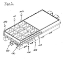
- FIG. 2 shows a perspective view of a arranged on the processing station 110 working tool 11.
- the processing station 110 has in addition to the bottom plate 101 and a terminal block 105 on which the bottom plate 101 is arranged.
- the terminal block 105 further includes a HubSchienenerhöhuhgsvorraum 106, with the in FIG. 2 not visible lifting rail 102 is coupled.
- Hubschienenerhöhungsvortechnik 106 means are provided which cause a lifting movement of the Hubschienenerhöhuhgsvortechnisch 106 and thus the lifting rail 102.
- the working tool 11 has at its opposite the bottom plate 101 Obterfestit in FIG. 3 shown protrusions 1110 in each one between the bottom plate 101 and the working tool 11 adjusting first gap 170, said protrusions 1110 have a smaller length or height than the first gap 170. Further, between these protrusions 1110 in each case a second gap 150 (FIG. Fig. 3 ) educated.
- This second intermediate space 150 is designed such that in an arrangement of the working tool 11 on the processing station 110, this is in each case brought into engagement with the lifting plates 102 arranged on the base plate 101.
- the extendable Scheiebesch 300 is arranged below the bottom plate 101.
- the sliding means 300 has at one end a coupling unit (not shown), which is coupled in an extended state of the sliding means 300 with the working tool 11 and thus enables the displacement of the working tool 11.
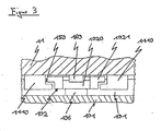
- FIG. 3 shows a partial sectional view through the working tool 11, the bottom plate 101 and the lifting rail 102. Clearly provides FIG. 3 an unfastened state of the working tool 11 on the bottom plate 101 is.
- the lifting rail 102 is arranged in the second gap 150 formed between the projections 1110 and has a rectangular area 1020 with a recess, the rectangular area 1020 being in contact with the lifting rail raising device 106 on one side. Furthermore, the lifting rail 102 has an L-shaped region 1021 on the sides perpendicular to the bottom plate 101. On the side of the lifting rail 102 facing away from the bottom plate 101, a sliding element 160 is arranged in the recess of the rectangular region of the lifting rail 102. Further, the slider 160 is on the side facing away from the recess with the working tool 11 in contact.
- the second intermediate space 150 formed between the projections 1110 is designed such that when the working tool 11 is fastened to the base plate 101, the L-shaped region of the lifting rail 102 is coupled to the respective projection 1110.
- two carriers 10 may be provided with only one receiving unit, wherein in the receiving unit of the first carrier 10, a working tool 11 is worn and the receiving unit of the second carriers 10 is empty.
- replacement of the work tools 11 by means of the two supports can be carried out without displacement of the receiving unit 13 and the lifting device 200 can be dispensed with.
- processing station is not limited to forming stations, but may also be used in other processing stations such as sealing and / or cutting stations and others.
Landscapes
- Engineering & Computer Science (AREA)
- Mechanical Engineering (AREA)
- Auxiliary Devices For And Details Of Packaging Control (AREA)
- Basic Packing Technique (AREA)
- Warehouses Or Storage Devices (AREA)
Description
- Die Erfindung betrifft eine Verpaskungsmaschine zum Verpacken von Produkten.
- Verpacknngsmaschinen zum Verpacken von Produkten weisen allgemein mehrere Bearbeitungsstationen auf. Insbesondere weisen dabei Verpackungsmaschihen häufig eine Tiefziehstation und eine der Tiefziehstation nachgeschaltete Siegelstation als Bearbeitungsst-ation auf. In der Tiefziehstation werden mittels eines Arbeitswerkzeugs in einer in der Verpackungsmaschine durchlaufenden Unterfolie Produktaufnahmeabschnitte ausgeformt, in die die zu verpackenden Produkte in einem der Tiefziehstation nachfolgenden Schritt eingefügt werden. Im Anschluss an das Einlegen der zu verpackenden Produkte in die Prodaktäüfnabmeabschnitte werden diese in der Siegelstation mit einer ebenfalls in der Verpackungsmaschine durchlaufenden Oberfolie verschlossen. Abhängig von der Größe der zu verpackenden Produkte muss auch die Größe des Produktsufnahmeabschnitts verändert werden. Somit Müssen abhängig von der Größe des zu verpackenden Produkts unterschiedliche Arbeitswerkzeuge verwendet werden. Dabei sollen diese Arbeitswerkzeuge möglichst einfach und ohne ein Beschädigen der Folie ausgewechselt werden können.
- In einem anderen technischen Gebiet, bei Kunststoffmaschinen, wird in der deutschen Offenlegungsschrift
DE 38 010 32 A1 eine Vorrichtung zum Wechseln von Werkzeugen offenbart, wobei ein Werkzeugwagen vor der Maschine positioniert wird. Zur Überbrückung des Abstandes zwischen Wagen und Maschine ist eine ausfluchtbare Werkzeugauflage ausfahrbar. Eine derartige Anordnung ist aber bei Verpackungsmaschinen gemäß dem Oberbegriff der vorliegenden Anmeldung nicht zweckmäßig, da der von außen herangeführte Werkzeugwagen die zu verarbeitende Oberfolie oder Unterfolie beschädigen könnte. - Aus der Druckschrift
EP 1 234 765 B1 ist eine Verpackungsmaschine bekannt, bei der ein Arbeitswerkzeug aus einer Ruheposition über eine Übergabeablage in eine Bearbeitungsstation und zurück überführt werden kann. Da die Überführung des Arbeitswerkzeugs jeweils unterhalb oder oberhalb der jeweiligen Folie erfolgt, kann ein Auswechseln des Arbeitswerkzeugs ohne ein Beschädigen der Folie erfolgen. - Durch die schrittweise Übergabe des Arbeitswerkzeugs ausgehend von der Ruheposition zu der Übergabeablage und zu der Bearbeitungsposition erhöht sich die Zeitdauer, die für die Übergabe des Arbeitswerkzeugs zu der Bearbeitungsstation und somit für den Verpackungsprozess insgesamt benötigt wird. Ferner ist infolge der einzelnen Stationen, die das Arbeitswerkzeug zu durchlaufen hat, der Aufbau der Verpackungsmaschine recht komplex.
- Die der vorliegenden Erfindung zu Grunde liegende Aufgabe besteht nun darin, eine Verpackungsmaschine bereitzustellen, bei der der Verpackungsprozess effizienter erfolgt und bei der die Verpackungsmaschine einfacher aufgebaut ist.
- Diese Aufgabe wird erfindungsgemäß durch die Merkmale des Patentanspruchs 1 gelöst. Vorteilhafte Ausgestaltungen der Erfindung sind in den Unteransprüchen gekennzeichnet.
- Die mit der Erfindung erzielten Vorteile bestehen insbesondere darin, dass der Aufbau der Verpackungsmaschine vereinfacht wird, indem das Arbeitswerkzeug direkt von einem Träger an die Bearbeitungsstation verschoben wird und keine dazwischenliegende Übergabeablage mehr vorhanden ist. Durch das direkte Verschieben des Arbeitswerkzeugs an die Bearbeitungsstation verkürzt sich auch die für den Verpackuhgsprozess benötigte Zeitdauer.
- Ein weiterer Vorteil der Erfindung besteht darin, dass der Träger aus der Verpackungsmaschine heraus bewegbar ist, womit die Arbeitswerkzeuge leichter zugänglich sind, um beispielsweise leichter gereinigt werden zu können.
- Eine weitere vorteilhafte Ausgestaltung der Erfindung besteht darin, dass eine Position der Aufnahmeeinheit, in der die Arbeitswerkzeuge angeordnet sind, mittels einer Hubvorrichtung verstellt werden kann, und somit das gewünschte Arbeitswerkzeug aus einer Vielzahl von Arbeitswerkzeugen ausgewählt werden kann, Auch besteht ein Vorteil darin, dass; zusätzlich ein Auswechseln des Arbeitswerkzeugs aus der Bearbeitungsstation effizienter erfolgte indem die Position der Aufnahmeeinheit durch die Hubvorrichtung derart eingestellt wird, dass ein Arbeitswerkzeug in einen leeren in der Aufnahmeeinheit befindlichen Aufnahmebereich verschoben wird. Somit ist ein zwischenseitliches Ablegen des Arbeitswerkzeugs auf eine Übergsbeablage nicht notwendig.
- Ferner besteht eine weitere Ausgestaltung der Erfindung darin, dass durch die Anordnung jeweils eines Arbeitswerkzeugs an jeder Seite einer an dem Träger Angeordneten drehbaren Platte, die zulässige Größe für das zu verwendende Arbeitswerkzeug und somit die Größe des Produktaufnahmebereichs erhöht wird.
- Eine weitere vorteilhafte Ausgestaltung der erfindung besteht darin, dass in der Bearbeitungsstation das Arbeitswerkzeug fest mit einer Bodenplatte gekoppelt wird. Dadurch erhöht sich die Bearbeitungsgenauigkeit des Arbeitswerkzeugs.
- Einzelheiten der Erfindung werden anhand der Zeichnung näher erläutert. Dabei zeigt:
-
Figur 1 : eine perspektivische Ansicht einer Verpackungsmaschine, bei der sich ein Träger außerhalb der Verpackungsmaschine befindet, -
Figur 2 : eine perspektivische Ansicht eines in einer Bearbeitungsstation angeordneten Arbeitswerkzeugs, -
Figur 3 : eine Teilschnittansicht durch das Arbeitswerkzeug, die Bodenplatte und eine Hubschiene. -
Figur 1 zeigt eine perspektivische Ansicht einer Verpackungsmaschine 1 und eines Trägers 10 außerhalb der Verpackungsmaschine 1. - Der Träger 10 weist ein Trägergestell 15 und eine auf dem Trägergestell 15 angeordnete Aufnahmeeinheit 13 zur Aufnahme von Arbeitswerkzeugen 11 auf. An dem Trägergestell 15 sind Rollen 16 angeordnet, die ein Bewegen des Trägers 10 ermöglichen. Ferner weist das Trägergestell 15 erste Führungselemente 17 auf, mittels denen die Bewegung des Trägers 10 in der Verpackungsmaschine 1 geführt wird.
- Die Arbeitswerkzeuge 11 werden in jeweils einem in der Aufnahmeeinheit 13 angeordneten Aufnahmebereich durch eine Auflage, die beispielsweise als Auflageschienen 12 ausgebildet ist, gehalten. Die einzelnen Aufnahmebereiche sind senkrecht zur Fahrtrichtung des Trägers 18 übereinander angeordnet. Ferner ist die Aufnahmeeinheit 13 derart am Trägergestell 15 angeordnet, dass die Aufnahmeeinheit 13 zu der Fahrtrichtung des Trägers 10 senkrecht verschiebbar ist. Diese Verschiebung der Aufnahmeeinheit 13 wird beispielsweise durch eine am Trägergestell 15 angebrachte Linearführung ermöglicht.
- Alternativ zum Träger kann ein (nicht dargestellter) träger zum Befördern von Arbeitswerkzeugen in die Verpackungsmaschine verwendet worden. Dieser Träger setzt sich aus einem Trägergestell und einer am Trägergestell angeordneten drehbaren platte zusammen. An dieser Platte ist an sieh gegenüberliegenden Seiten der Platte jeweils mindestens ein Arbeitswerkzeug angeordnet. Die Platte ist dabei um eine vorzugsweise in der Mitte der Platte angebrachte Drehachse drehbar.
- Die Verpackungsmaschine 1 weist zwei sich gegenüberliegende Schienen 103 auf, in denen Mittel zum Befördern einer in der
Figur 1 nicht dargestellten Oberfolie und/ oder Unterfolie untergebracht sind. Auch weist die Verpackuhgsmaschine 1 eine in einer Bearbeitungsstation 110, die beispielsweise als Tiefsiehstation ausgebildet sein kann, angeordnete Bodenplatte 101 auf, wobei an der Bodenplatte 101 Hubschienen 102 angeordnet sind, mittels denen das aus dem Träger 10 verschobene Arbeitswerkzeug 11 auf der Bodenplatte 101 geführt und befestigt wird. Sobald das Arbeitswerkzeug 11 durch die Hubschiene 102 befestigt wird, kann ein Ausbilden von Produktäufnahmeabschnitten in einer Unterfolie mittels des befestigten Arbeitswerkzeugs 11 erfolgen. - Ferner weist die Verpackungsmaschine 1 einen zu der Bearbeitungsstation 110 benachbarten Raumabschnitt 111 auf, in den der Träger 10 zum Auswechseln und/ oder Zuführen eines Arbeitswerkzeugs 11 hineinfahrbar ist. Der zur Bearbeitungsstation 110 benachbarte Raumabschnitt 111 wird durch zwei zur Fahrtrichtung des Trägers 10 parallele zweite Führungselemente 120 und eines zu den zweiten Führungselementen 120 quer verlaufenden Balken 121 begrenzt. Ferner wird der Raumabschnitt 111 in der zur Fahrtrichtung des Trägers 10 senkrechten Richtung durch die in
Figur 1 nicht dargestellte Unterfolie begrenzt. Die Verpackungsmaschine 1 weist in der zum Träger 10 weisenden Richtung des Raumabschnitt 111 eine Öffnung 100 auf, durch die der Trager 10 in den Raumabschnitt 111 hinein gefahren werden kann. Diese Öffnung 100 stellt für die Geometrie des Trägers 10 eine Begrenzung dar, da dieser derart ausgebildet sein muss, dass auch das vom Trägergestell 15 am entferntesten liegende Arbeitswerkzeug durch die Öffnung 100 passt, da ansonsten der Träger 10 nicht in die Verpackungsmaschine 1 hinein gefahren werden kann. Somit wird die Anzahl und/ oder die Größe der Aufnahmebreiche durch die Geometrie der Verpackungsmaschine 1, insbesondere der Öffnung 100 begrenzte - Bei einem Hineinfahren des Trägers 10 in die Verpackungsmaschine 1 wird die Bewegungsrichtung des Trägers 10 durch die an dem Trägergestell 15 angeordneten ersten Führungselemente 17, die während des Hiheinfahrens des Trägers in die Verpackungsmaschine 1 durch die an der Verpackungsmashine 1 angebrachten zweiten Führungselemente 120 geführt werden, bestimmt. Der in Fahrtrichtung des Trägers 10 mögliche Bewegungsweg des Trägers 10 wird durch den zu den zweiten Führungselementen 120 quer verlaufenden Balken 121 begrenzt. Ein Herausfahren des Trägers 10 aus der Verpackungsmaschine 1 kann beispielsweise durch Befestigungsmittel oder eine bestimmte Ausbildung der zweiten Führungselemente 120 verhindert werden.
- In diesem Fall handelt es sich bei den am Träger 10 angeordneten ersten Führüngseletnenten 17 um Führungsrollen und bei den an der Verpackungsmaschine 1 angebrachten zweiten Führuhgselemehten 120 um Führungsschienen. Es sind aber auch andere an dem Träger 10 und/ oder an der Verpackungsmaschine 1 angebrachte erste und zweite Führungselemente denkbar, die eine Bewegung dos Trägers 10 in der Verpackungsmaschine 1 führen.
- Ferner weist die Verpackungsmaschine 1 eine Hubvorrichtung 200 auf, die vorsugsweise als ein Pneumatikzylinder ausgebildet ist, mittels der ein Auswählen des Aufnahmebereichs der Aufnahmeeinheit ermöglicht wird Mittels der Hubvorrichtung 200 Wird der Aufnahmebereich mit dem ausgewählten Arbeitswerkzeug 11 relativ zum Trägergestell 15 derart verschoben bis die Auflageschienen 12 des ausgewählten Aufnahmebereichs bezüglich der Bodenplatte 101 derart angeordnet sind, dass ein Verschieben des Arbeitswerkzeugs 11 von dem Träger 10 auf die Bodenstation 110 sichergestellt ist. Bei einem Verschieben des Arbeitswerkzeugs 11 aus der Bearbeitungsstatien 110 in einen leeren Aufnahmeberich der Aufnahmeeinheit 13 wird analog wie oben beschrieben mittels der Hubvorrichtung 200 die Aufnahmeeinheit 13 derart verschoben, bis ein Verschieben des Arbeitswerkzeugs 11 aus der Bearbeitungsstation 110 in den leeren Aufnahmebereich des Trägers 10 sichergestellt ist. Die Verschiebung des Arbeitswerkseugs 11 erfolgt in beiden Fällen Mittels eines Schiebemittels 300.
- Dabei ist auch sichergestellt, dass der Träger 10 derart ausgebildet ist, dass in der maximalen Auslenkung der Hubvorrichtung 200 und damit beim maximalen Abstand des vom Trägergestell 15 am weitest entfernt liegenden Aufnahmebereichs, das in diesem Aufnahmebereich gehaltene Arbeitswerkzeug 11 die in bzw. zwischen den Schienen 103 angeordnete Unterfolie nicht berühren und somit beschädigen kann.
-
Figur 2 zeigt eine perspektivische Ansicht eines auf der Bearbeitungsstation 110 angeordneten Arbeitswerkzeugs 11. Die Bearbeitungsstation 110 weist neben der Bodenplatte 101 auch einen Anschlussbock 105 auf, auf dem die Bodenplatte 101 angeordnet ist. Der Anschlussbock 105 weist ferner eine HubSchienenerhöhuhgsvorrichtung 106 auf, die mit der inFigur 2 nicht sichtbaren Hubschiene 102 gekoppelt ist. In dieser Hubschienenerhöhungsvorrichtung 106 sind Mittel vorgesehen, die eine Hubbewegung der Hubschienenerhöhuhgsvorrichtung 106 und damit der Hubschiene 102 bewirken. - Das Arbeitswerkzeug 11 weist an seinen zur Bodenplatte 101 gegenüberliegenden Obterflächenseiten in
Figur 3 dargestellte Vorsprünge 1110 in jeweils einem sich zwischen der Bodenplatte 101 und dem Arbeitswerkzeug 11 einstellenden ersten Zwischenraums 170 auf, wobei diese Vorsprünge 1110 eine kleinere Länge bzw. Höhe aufweisen als der erste Zwischenraum 170. Ferner ist zwischen diesen Vorsprüngen 1110 jeweils ein zweiter Zwischenraum 150 (Fig. 3 ) ausgebildet. Dieser zweite Zwischenraum 150 ist dabei derart ausgebildet, dass bei einer Anordnung des Arbeitswerkzeugs 11 auf der Bearbeitungsstation 110 diese jeweils mit den auf der Bodenplatte 101 angeordneten Hubschienen 102 in Eingriff gebracht wird. - Ferner ist in der Bearbeitungsstation 110, unterhalb der Bodenplatte 101, das ausfahrbare Scheiebemittel 300 angeordnet. Das Schiebemittel 300 weist dabei an einem Ende eine (nicht gezeigte) Koppeleinheit auf, die in einem ausgefahrenen Zustand des Schiebemittels 300 mit dem Arbeitswerkzeug 11 gekoppelt wird und somit die Verschiebung des Arbeitswerkzeugs 11 ermöglicht.
-
Figur 3 zeigt eine Teilschnittansicht durch das Arbeitswerkzeug 11, die Bodenplatte 101 und die Hubschiene 102. Dabei stelltFigur 3 einen unbefestigten Zustand des Arbeitswerkzeugs 11 an der Bodenplatte 101 dar. - Die Hubschiene 102 ist in dem zischen den Vorsprüngen 1110 ausgebildeten zweiten Zwischenraum 150 angeordnet, und weist einen rechteckigen Bereich 1020 mit einer Aussparung auf, wobei der rechteckige Bereich 1020 an einer Seite mit der Hubschienenerhöhungsvorrchtung 106 in Kontakt steht. Ferner weist die Hubschiene 102 an den zur Bodenplatte 101 senkrecht angeordneten Seiten jeweils einen L-förmigen Bereich 1021 auf, Auf der von der Bodenplatte 101 abgewandten Seite der Hubschiene 102 ist in der Aussparung des rechteckigen Bereichs der Hubschiene 102 ein Gleitelement 160 angeordnet. Ferner steht das Gleitelement 160 an der der Aussparung abgewandten Seite mit dem Arbeitswerkzeug 11 in Kontakt. Der sich zwischen den Vorsprüngen 1110 ausgebildete zweite Zwischenraum 150 ist dabei derart ausgebildet, dass bei einem Befestigen des Arbeitswerkzeugs 11 an der Bodenplatte 101 der L-förmige Bereich der Hubschiene 102 mit dem jeweiligen Vorsprung 1110 gekoppelt ist.
- Bei einer Befestigung des Arbeitswerkzeugs 11 auf der Bodenplatte 101 wird durch die Hubschienenerhöhungsvorriohtung 106 eine in Richtung der Bodenplatte 101 weisende Kraft auf die Hubschiene 102 ausgeübt, die sich infolge davon in diese Richtung bewegt. Durch die Bewegung der Hubschiene 102 in Richtung zur Bodenplatte 101 wird über den L-förmigen Bereich 1021 der Hubschiene 102 die in Richtung zur Bodenplatte 101 gerichtete Kraft auf den jeweiligen Vorsprung 1110 und damit das Arbeitswerkzeug 11 übertragen, wodurch sich das Arbeitswerkzeug 11 ebenfalls in Richtung zur Bodenplatte 101 bewegt und somit an der Bodenplatte 101 fixiert wird.
- Statt der Vielzahl von Aufnahmebereichen in der am Träger 10 angeordneten Aufnahmeeinheit 13 können auch zwei Träger 10 mit nur jeweils einer Aufnahmeeinheit vorgesehen sein, wobei in der Aufnahmeeinheit des ersten Tragers 10 ein Arbeitswerkzeug 11 getragen wird und die Aufnahmeeinheit des zweiten Trägern 10 leer ist. Somit kann ein Auswechseln der Arbeitswerkzeuge 11 mittels der zwei Träger ohne eine Verschiebung der Aufnahmeeinheit 13 erfolgen und auf dieHubvorrichtung 200 kann verzichtet werden.
- Ferner ist die Bearbeitungsstation nicht auf Formstationen beschränkt, sondern kann auch bei anderen Bearbeitunsstationen wie beispielsweise Siegel- und/ oder Schneidstationen und weiteren verwendet werden.
Claims (10)
- Verpackungsmaschine (1) mit einem Träger (10) auf dem mindestens ein Arbeitswerkzeug (11) anordenbar ist und einer Bearbeitungsstation (110), auf die das Arbeitswerkzeug (11) mittels eines Schiebemittels (300) verschiebbar ist oder von der ausgehend ein Arbeitswerkzeug (11) mittels des Schiebemittels (300) auf den Träger (10) verschiebbar ist, wobei die Verschiebung des Arbeitswerkzeugs (11) berührungsfrei zu einer in der Verpackungsmaschine (1) angeordneten Oberfolie oder Unterfolie erfolgt,
dadurch gekennzeichnet, dass
der Träger (10) aus der Verpackungsmaschine (1) heraus bewegbar ist, wobei über ein jeweils an dem Träger (10) und in der Verpackungsmaschine (1) angeordnetes erstes und zweites Führungselement (17, 120) eine Bewegungsrichtung des Trägers (10) in der Verpackungsmaschine (1) festlegbar ist. - Verpackungsmaschine (1) nach Anspruch 1, wobei mehrere übereinander angeordnete Arbeitswerkzeuge (11) jeweils in einem Aufnahmebereich einer an dem Träger (10) angeordneten Aufnahmeeinheit (13) anordenbar sind.
- Verpackungsmaschine nach Anspruch 1 oder 2, wobei der Träger (10) eine um eine Drehachse drehbare Platte aufweist, wobei auf zwei sich gegenüberliegenden Seiten der Platte jeweils ein Arbeitswerkzeug (11) anordenbar ist.
- Verpackungsmaschine (1) nach einem der vorhergehenden Ansprüche, wobei in der Verpackungsmaschine (1) eine Hubvorrichtung (200) angeordnet ist, die mit dem Träger (10) im wesentlichen auf einem Niveau ist.
- Verpackungsmaschine (1) nach Anspruch 4, wobei in der Verpackungsmaschine (1) die Hubvorrichtung (200) mit der Aufnahmeeinheit (13) in Kontakt steht.
- Verpackungsmaschine nach einem der Ansprüche 2 bis 5, wobei im Aufnahmebereich eine Auflage vorgesehen ist, die das Arbeitswerkzeug (11) trägt.
- Verpackungsmaschine (1) nach einem der vorhergehenden Ansprüche, wobei in der Bearbeitungsstation (110) das Arbeitswerkzeug (11) über eine Hubschiene (102) auf einer Bodenplatte (101) fixierbar ist.
- Verpackungsmaschine nach einem der vorhergehenden Ansprüche, wobei das Arbeitswerkzeug (11) mehrere Vorsprünge (1110) mit einem zwischen den Vorsprüngen (1110) angeordneten Zwischenraum (150) aufweist.
- Verpackungsmaschine nach einem der vorhergehenden Ansprüche, wobei das Schiebemittel (300) an einem Ende eine Koppeleinheit aufweist, mit der das Arbeitswerkzeug (11) in Eingriff bringbar ist.
- Verpackungsmaschine nach einem der vorhergehenden Ansprüche, wobei die Bearbeitungsstation (110) einer Tiefziehstation entspricht.
Applications Claiming Priority (1)
| Application Number | Priority Date | Filing Date | Title |
|---|---|---|---|
| DE102008019628A DE102008019628A1 (de) | 2008-04-18 | 2008-04-18 | Verpackungsmaschine |
Publications (2)
| Publication Number | Publication Date |
|---|---|
| EP2110219A1 EP2110219A1 (de) | 2009-10-21 |
| EP2110219B1 true EP2110219B1 (de) | 2011-06-08 |
Family
ID=40874618
Family Applications (1)
| Application Number | Title | Priority Date | Filing Date |
|---|---|---|---|
| EP09158069A Active EP2110219B1 (de) | 2008-04-18 | 2009-04-16 | Verpackungsmaschine |
Country Status (5)
| Country | Link |
|---|---|
| US (1) | US8028504B2 (de) |
| EP (1) | EP2110219B1 (de) |
| AT (1) | ATE511971T1 (de) |
| DE (1) | DE102008019628A1 (de) |
| ES (1) | ES2367608T3 (de) |
Families Citing this family (21)
| Publication number | Priority date | Publication date | Assignee | Title |
|---|---|---|---|---|
| AU2004100000A4 (en) | 2004-01-02 | 2004-02-12 | Sands Innovations Pty Ltd | Dispensing stirring implement |
| AU2008210267B2 (en) | 2007-01-31 | 2014-06-12 | Sands Innovations Pty Ltd | A dispensing utensil and manufacturing method therefor |
| JP5332346B2 (ja) * | 2008-06-30 | 2013-11-06 | 株式会社湯山製作所 | 薬剤包装装置及び包装ユニット交換用台車 |
| AU2008365185B2 (en) | 2008-12-09 | 2016-05-05 | Sands Innovations Pty Ltd | A dispensing container |
| US8499536B2 (en) | 2009-05-18 | 2013-08-06 | Alkar-Rapidpak-Mp Equipment, Inc. | Apparatuses and methods for assisted tooling extraction |
| USD636890S1 (en) | 2009-09-17 | 2011-04-26 | Sands Innovations Pty. Ltd. | Dispensing utensil |
| DE102010009536A1 (de) | 2010-02-26 | 2011-09-01 | Cfs Germany Gmbh | Verfahren zum Wechsel des Ober- und Unterwerkzeugs einer Verpackungsmaschine |
| US8511500B2 (en) | 2010-06-07 | 2013-08-20 | Sands Innovations Pty. Ltd. | Dispensing container |
| US8485360B2 (en) | 2011-03-04 | 2013-07-16 | Sands Innovations Pty, Ltd. | Fracturable container |
| US9156573B2 (en) | 2011-03-30 | 2015-10-13 | Alkar-Rapidpak, Inc. | Packaging apparatuses and methods |
| DE102011101051A1 (de) * | 2011-05-10 | 2012-11-15 | Multivac Sepp Haggenmüller Gmbh & Co. Kg | Werkzeugwechseleinrichtung |
| DE102011101053B4 (de) * | 2011-05-10 | 2014-06-05 | Multivac Sepp Haggenmüller Gmbh & Co. Kg | Arbeitsstation für eine Verpackungsmaschine und Verfahren zum Werkzeugwechsel |
| DE102011113968A1 (de) * | 2011-09-21 | 2013-03-21 | Multivac Sepp Haggenmüller Gmbh & Co. Kg | Schalenverschließmaschine |
| DE102012003830A1 (de) * | 2012-02-29 | 2013-08-29 | Gea Cfs Germany Gmbh | Verpackungsmaschine mit einem auswechselbaren Werkzeug |
| GB201205150D0 (en) * | 2012-03-23 | 2012-05-09 | Ishida Europ Ltd | Tool handling system |
| PT2886299T (pt) | 2013-12-18 | 2017-02-10 | Ulma Packaging Tech Ct Coop | Método de alteração de formato para uma máquina de termoformação, e máquina de termoformação |
| DE102017107243A1 (de) * | 2017-04-04 | 2018-10-04 | Multivac Sepp Haggenmüller Se & Co. Kg | Verpackungsmaschine mit neigbarer werkzeugschublade |
| ES2824528T3 (es) * | 2017-12-21 | 2021-05-12 | Multivac Haggenmueller Kg | Carro de almacenamiento para cubiertas de protección |
| EP4059848B1 (de) | 2021-03-17 | 2024-02-28 | Bizerba SE & Co. KG | Verpackungsmaschine mit integrierter reinigungshilfe |
| DE102023108015A1 (de) | 2023-03-29 | 2024-10-02 | Multivac Sepp Haggenmüller Se & Co. Kg | Tiefziehverpackungsmaschine mit einer Schneidstation und Verfahren zum Herausnehmen eines Schneidwerkzeugs einer Tiefziehverpackungsmaschine |
| DE102023111019A1 (de) | 2023-04-28 | 2024-10-31 | Multivac Sepp Haggenmüller Se & Co. Kg | Werkzeugwechsel an einer Arbeitsstation für eine Verpackungsmaschine |
Family Cites Families (22)
| Publication number | Priority date | Publication date | Assignee | Title |
|---|---|---|---|---|
| US3871611A (en) * | 1973-05-07 | 1975-03-18 | Taketa Phyllis | Mold with removable and replaceable core and cavity inserts |
| GB1460291A (en) * | 1973-05-08 | 1976-12-31 | Gkn Windsor Ltd | Injection moulding machines |
| US4056207A (en) * | 1976-07-15 | 1977-11-01 | Spilker James W | Die changer |
| US4202522A (en) * | 1977-06-16 | 1980-05-13 | Honeywell Inc. | Injection molding apparatus for accommodating various sizes of molding die inserts |
| JPS5734915A (en) * | 1980-08-12 | 1982-02-25 | Tamagawa Kikai Kk | Replacing mechanism for die set in powder molding press etc |
| EP0092685B2 (de) * | 1982-04-26 | 1995-08-02 | Battenfeld GmbH | Schnellwechsel- und/oder Spannvorrichtung für die Formwerkzeuge von Spritzgiessmaschinen |
| US4614108A (en) * | 1985-04-12 | 1986-09-30 | Tek-Matik, Inc. | Die cart |
| DE3801032A1 (de) * | 1988-01-15 | 1989-07-27 | Kermi Gmbh | Vorrichtung zum wechseln von werkzeugen bei kunststoffmaschinen oder dergleichen |
| DE3904798A1 (de) * | 1989-02-17 | 1990-08-30 | Wagner Foerdertechnik | Hubwagen mit einer in vertikaler richtung federbelastet vorgespannten antriebseinheit |
| FR2648432B1 (fr) * | 1989-06-16 | 1991-09-13 | Mecaplastic | Dispositif et installation pour le conditionnement de produits quelconques, par exemple de produits alimentaires, dans des barquettes fermees par un film soude de fermeture |
| US5074143A (en) * | 1989-12-14 | 1991-12-24 | Alpha Industries, Inc. | Cart for removing and installing dies in a cut-off press |
| US5040404A (en) * | 1990-10-31 | 1991-08-20 | Chrysler Corporation | Die changing system and apparatus for stamping presses |
| DE9113290U1 (de) * | 1991-10-25 | 1991-12-19 | Krämer + Grebe GmbH & Co KG Maschinenfabrik, 3560 Biedenkopf | Vorrichtung zum Herstellen einer Verpackung |
| IT1262791B (it) * | 1993-05-11 | 1996-07-04 | Isap Omv Group Spa | Metodo di sostituzione degli stampi in un'apparecchio di termoformatura di oggetti a partire da nastro di materiale termoplastico |
| JP3420328B2 (ja) * | 1994-05-30 | 2003-06-23 | 株式会社小松製作所 | プレスの金型交換方法 |
| US5940953A (en) * | 1997-09-03 | 1999-08-24 | Brown Machine Llc. | Cart and method for changing tooling in a thermoformer machine |
| DE19824589A1 (de) * | 1998-06-02 | 1999-12-09 | Kraemer & Grebe Kg | Siegelwerkzeug und Verfahren zum Siegeln von Verpackungen |
| US6543983B1 (en) * | 1998-07-07 | 2003-04-08 | University Of Virginia Patent Foundation | Robotic pick up and deliver system |
| DE10108163A1 (de) | 2001-02-20 | 2002-08-29 | Ps Systempack Gmbh | Vorrichtung an einer Tiefzieh-Verpackungsmaschine |
| EP1598275A1 (de) * | 2004-05-19 | 2005-11-23 | CFS Palazzolo S.p.A. | Vorrichtung zur Handhabung eines abnehmbaren Werkzeugs in einer Maschine, insbesondere einer Verpackungsmaschine, und Verfahren |
| US7220222B2 (en) * | 2005-01-19 | 2007-05-22 | Multi-Shifter Inc. | Cart for die transportation |
| US7340871B1 (en) * | 2006-03-31 | 2008-03-11 | Alkar-Rapidpak, Inc. | Web packaging system with ergonomic tooling change |
-
2008
- 2008-04-18 DE DE102008019628A patent/DE102008019628A1/de not_active Withdrawn
-
2009
- 2009-04-16 AT AT09158069T patent/ATE511971T1/de active
- 2009-04-16 EP EP09158069A patent/EP2110219B1/de active Active
- 2009-04-16 ES ES09158069T patent/ES2367608T3/es active Active
- 2009-04-17 US US12/386,494 patent/US8028504B2/en not_active Expired - Fee Related
Also Published As
| Publication number | Publication date |
|---|---|
| ATE511971T1 (de) | 2011-06-15 |
| EP2110219A1 (de) | 2009-10-21 |
| ES2367608T3 (es) | 2011-11-04 |
| DE102008019628A1 (de) | 2009-11-05 |
| US20090266028A1 (en) | 2009-10-29 |
| US8028504B2 (en) | 2011-10-04 |
Similar Documents
| Publication | Publication Date | Title |
|---|---|---|
| EP2110219A1 (de) | Verpackungsmaschine | |
| DE3223264C2 (de) | Vorrichtung zum automatischen Montieren von Teilen | |
| EP0170802A1 (de) | Führungsvorrichtung für zwei aneinander längsbeweglich gelagerte und angetriebene Maschinenteile | |
| DE2417131A1 (de) | Pressenstrasse mit werkstuecktransportvorrichtung | |
| EP2415675B1 (de) | Vorrichtung zum Fördern von Gegenständen in Verpackungsmaschinen | |
| DE19654475A1 (de) | Transfereinrichtung und Mehrstationenpresse | |
| EP3370892B1 (de) | Greifersystem für eine biegepresse | |
| DE202014006420U1 (de) | Transfermodul, Montagemodul und Umsetzmodul für ein modulares Montage-Transfersystem sowie modulares Montage-Transfersystem | |
| DE2656622A1 (de) | Bewegliche abdeckung fuer energiefuehrungsleitungen, fuehrungsbahnen und sonstige einrichtungen | |
| EP1075943B1 (de) | Druckwerk | |
| DE102004002143A1 (de) | Transportvorrichtung | |
| EP3056440A1 (de) | Objektträger und Verpackungsanlage | |
| EP2772445B1 (de) | Verstellportal, Schrumpfvorrichtung mit einstellbaren Schachtwänden und Verfahren zur Einstellung von Schachtwänden | |
| DE29716104U1 (de) | Spannvorrichtung, insbesondere Maschinenschraubstock | |
| DE102019218366A1 (de) | Formförderführungsvorrichtung und Spritzgiessmaschine | |
| DE102018130595B4 (de) | Sensorstation sowie Verfahren zum Vermessen von Wafern | |
| EP2845663B1 (de) | Biegepresse mit einem Biegewerkzeug aus mehreren Werkzeugelementen | |
| DE102014202995A1 (de) | Rahmen für ein Strangführungssegment | |
| DE3529775A1 (de) | Vorrichtung zur herstellung von formteilen | |
| DE2736849C3 (de) | Spinn- oder Zwirnanlage | |
| EP0376246B1 (de) | Palettenwechsler | |
| EP2955416B1 (de) | Antriebsvorrichtung und station einer verpackungsmaschine | |
| WO2001038043A1 (de) | Werkzeugmaschine oder handhabungsgerät mit einem maschinengestell und einer daran längs einer bewegungsachse antreibbaren maschineneinheit | |
| EP2706248B1 (de) | Linearführung | |
| DE19739270C1 (de) | Spannvorrichtung, insbesondere Maschinenschraubstock |
Legal Events
| Date | Code | Title | Description |
|---|---|---|---|
| PUAI | Public reference made under article 153(3) epc to a published international application that has entered the european phase |
Free format text: ORIGINAL CODE: 0009012 |
|
| AK | Designated contracting states |
Kind code of ref document: A1 Designated state(s): AT BE BG CH CY CZ DE DK EE ES FI FR GB GR HR HU IE IS IT LI LT LU LV MC MK MT NL NO PL PT RO SE SI SK TR |
|
| 17P | Request for examination filed |
Effective date: 20091124 |
|
| 17Q | First examination report despatched |
Effective date: 20100809 |
|
| GRAP | Despatch of communication of intention to grant a patent |
Free format text: ORIGINAL CODE: EPIDOSNIGR1 |
|
| RIN1 | Information on inventor provided before grant (corrected) |
Inventor name: HOLZEM, DIETER Inventor name: ZELLER, HUBERT |
|
| GRAS | Grant fee paid |
Free format text: ORIGINAL CODE: EPIDOSNIGR3 |
|
| GRAA | (expected) grant |
Free format text: ORIGINAL CODE: 0009210 |
|
| AK | Designated contracting states |
Kind code of ref document: B1 Designated state(s): AT BE BG CH CY CZ DE DK EE ES FI FR GB GR HR HU IE IS IT LI LT LU LV MC MK MT NL NO PL PT RO SE SI SK TR |
|
| REG | Reference to a national code |
Ref country code: GB Ref legal event code: FG4D Free format text: NOT ENGLISH |
|
| REG | Reference to a national code |
Ref country code: CH Ref legal event code: EP |
|
| REG | Reference to a national code |
Ref country code: IE Ref legal event code: FG4D Free format text: LANGUAGE OF EP DOCUMENT: GERMAN |
|
| REG | Reference to a national code |
Ref country code: DE Ref legal event code: R096 Ref document number: 502009000730 Country of ref document: DE Effective date: 20110721 |
|
| REG | Reference to a national code |
Ref country code: NL Ref legal event code: T3 |
|
| PG25 | Lapsed in a contracting state [announced via postgrant information from national office to epo] |
Ref country code: HR Free format text: LAPSE BECAUSE OF FAILURE TO SUBMIT A TRANSLATION OF THE DESCRIPTION OR TO PAY THE FEE WITHIN THE PRESCRIBED TIME-LIMIT Effective date: 20110608 Ref country code: SE Free format text: LAPSE BECAUSE OF FAILURE TO SUBMIT A TRANSLATION OF THE DESCRIPTION OR TO PAY THE FEE WITHIN THE PRESCRIBED TIME-LIMIT Effective date: 20110608 Ref country code: LT Free format text: LAPSE BECAUSE OF FAILURE TO SUBMIT A TRANSLATION OF THE DESCRIPTION OR TO PAY THE FEE WITHIN THE PRESCRIBED TIME-LIMIT Effective date: 20110608 Ref country code: NO Free format text: LAPSE BECAUSE OF FAILURE TO SUBMIT A TRANSLATION OF THE DESCRIPTION OR TO PAY THE FEE WITHIN THE PRESCRIBED TIME-LIMIT Effective date: 20110908 |
|
| REG | Reference to a national code |
Ref country code: ES Ref legal event code: FG2A Ref document number: 2367608 Country of ref document: ES Kind code of ref document: T3 Effective date: 20111104 |
|
| PG25 | Lapsed in a contracting state [announced via postgrant information from national office to epo] |
Ref country code: CY Free format text: LAPSE BECAUSE OF FAILURE TO SUBMIT A TRANSLATION OF THE DESCRIPTION OR TO PAY THE FEE WITHIN THE PRESCRIBED TIME-LIMIT Effective date: 20110608 Ref country code: FI Free format text: LAPSE BECAUSE OF FAILURE TO SUBMIT A TRANSLATION OF THE DESCRIPTION OR TO PAY THE FEE WITHIN THE PRESCRIBED TIME-LIMIT Effective date: 20110608 Ref country code: SI Free format text: LAPSE BECAUSE OF FAILURE TO SUBMIT A TRANSLATION OF THE DESCRIPTION OR TO PAY THE FEE WITHIN THE PRESCRIBED TIME-LIMIT Effective date: 20110608 Ref country code: GR Free format text: LAPSE BECAUSE OF FAILURE TO SUBMIT A TRANSLATION OF THE DESCRIPTION OR TO PAY THE FEE WITHIN THE PRESCRIBED TIME-LIMIT Effective date: 20110909 Ref country code: LV Free format text: LAPSE BECAUSE OF FAILURE TO SUBMIT A TRANSLATION OF THE DESCRIPTION OR TO PAY THE FEE WITHIN THE PRESCRIBED TIME-LIMIT Effective date: 20110608 |
|
| REG | Reference to a national code |
Ref country code: IE Ref legal event code: FD4D |
|
| PG25 | Lapsed in a contracting state [announced via postgrant information from national office to epo] |
Ref country code: CZ Free format text: LAPSE BECAUSE OF FAILURE TO SUBMIT A TRANSLATION OF THE DESCRIPTION OR TO PAY THE FEE WITHIN THE PRESCRIBED TIME-LIMIT Effective date: 20110608 Ref country code: PT Free format text: LAPSE BECAUSE OF FAILURE TO SUBMIT A TRANSLATION OF THE DESCRIPTION OR TO PAY THE FEE WITHIN THE PRESCRIBED TIME-LIMIT Effective date: 20111010 Ref country code: IS Free format text: LAPSE BECAUSE OF FAILURE TO SUBMIT A TRANSLATION OF THE DESCRIPTION OR TO PAY THE FEE WITHIN THE PRESCRIBED TIME-LIMIT Effective date: 20111008 Ref country code: IE Free format text: LAPSE BECAUSE OF FAILURE TO SUBMIT A TRANSLATION OF THE DESCRIPTION OR TO PAY THE FEE WITHIN THE PRESCRIBED TIME-LIMIT Effective date: 20110608 Ref country code: EE Free format text: LAPSE BECAUSE OF FAILURE TO SUBMIT A TRANSLATION OF THE DESCRIPTION OR TO PAY THE FEE WITHIN THE PRESCRIBED TIME-LIMIT Effective date: 20110608 |
|
| PG25 | Lapsed in a contracting state [announced via postgrant information from national office to epo] |
Ref country code: PL Free format text: LAPSE BECAUSE OF FAILURE TO SUBMIT A TRANSLATION OF THE DESCRIPTION OR TO PAY THE FEE WITHIN THE PRESCRIBED TIME-LIMIT Effective date: 20110608 Ref country code: SK Free format text: LAPSE BECAUSE OF FAILURE TO SUBMIT A TRANSLATION OF THE DESCRIPTION OR TO PAY THE FEE WITHIN THE PRESCRIBED TIME-LIMIT Effective date: 20110608 |
|
| PLBE | No opposition filed within time limit |
Free format text: ORIGINAL CODE: 0009261 |
|
| STAA | Information on the status of an ep patent application or granted ep patent |
Free format text: STATUS: NO OPPOSITION FILED WITHIN TIME LIMIT |
|
| 26N | No opposition filed |
Effective date: 20120309 |
|
| PG25 | Lapsed in a contracting state [announced via postgrant information from national office to epo] |
Ref country code: IT Free format text: LAPSE BECAUSE OF FAILURE TO SUBMIT A TRANSLATION OF THE DESCRIPTION OR TO PAY THE FEE WITHIN THE PRESCRIBED TIME-LIMIT Effective date: 20110608 |
|
| PG25 | Lapsed in a contracting state [announced via postgrant information from national office to epo] |
Ref country code: DK Free format text: LAPSE BECAUSE OF FAILURE TO SUBMIT A TRANSLATION OF THE DESCRIPTION OR TO PAY THE FEE WITHIN THE PRESCRIBED TIME-LIMIT Effective date: 20110608 |
|
| REG | Reference to a national code |
Ref country code: DE Ref legal event code: R097 Ref document number: 502009000730 Country of ref document: DE Effective date: 20120309 |
|
| BERE | Be: lapsed |
Owner name: MULTIVAC SEPP HAGGENMULLER G.M.B.H. & CO KG Effective date: 20120430 |
|
| PG25 | Lapsed in a contracting state [announced via postgrant information from national office to epo] |
Ref country code: MC Free format text: LAPSE BECAUSE OF NON-PAYMENT OF DUE FEES Effective date: 20120430 |
|
| PG25 | Lapsed in a contracting state [announced via postgrant information from national office to epo] |
Ref country code: BE Free format text: LAPSE BECAUSE OF NON-PAYMENT OF DUE FEES Effective date: 20120430 |
|
| PG25 | Lapsed in a contracting state [announced via postgrant information from national office to epo] |
Ref country code: MK Free format text: LAPSE BECAUSE OF FAILURE TO SUBMIT A TRANSLATION OF THE DESCRIPTION OR TO PAY THE FEE WITHIN THE PRESCRIBED TIME-LIMIT Effective date: 20110608 |
|
| PG25 | Lapsed in a contracting state [announced via postgrant information from national office to epo] |
Ref country code: BG Free format text: LAPSE BECAUSE OF FAILURE TO SUBMIT A TRANSLATION OF THE DESCRIPTION OR TO PAY THE FEE WITHIN THE PRESCRIBED TIME-LIMIT Effective date: 20110908 |
|
| PG25 | Lapsed in a contracting state [announced via postgrant information from national office to epo] |
Ref country code: MT Free format text: LAPSE BECAUSE OF FAILURE TO SUBMIT A TRANSLATION OF THE DESCRIPTION OR TO PAY THE FEE WITHIN THE PRESCRIBED TIME-LIMIT Effective date: 20110608 |
|
| REG | Reference to a national code |
Ref country code: CH Ref legal event code: PL |
|
| GBPC | Gb: european patent ceased through non-payment of renewal fee |
Effective date: 20130416 |
|
| PG25 | Lapsed in a contracting state [announced via postgrant information from national office to epo] |
Ref country code: GB Free format text: LAPSE BECAUSE OF NON-PAYMENT OF DUE FEES Effective date: 20130416 Ref country code: CH Free format text: LAPSE BECAUSE OF NON-PAYMENT OF DUE FEES Effective date: 20130430 Ref country code: LI Free format text: LAPSE BECAUSE OF NON-PAYMENT OF DUE FEES Effective date: 20130430 |
|
| PG25 | Lapsed in a contracting state [announced via postgrant information from national office to epo] |
Ref country code: LU Free format text: LAPSE BECAUSE OF NON-PAYMENT OF DUE FEES Effective date: 20120416 |
|
| PG25 | Lapsed in a contracting state [announced via postgrant information from national office to epo] |
Ref country code: HU Free format text: LAPSE BECAUSE OF FAILURE TO SUBMIT A TRANSLATION OF THE DESCRIPTION OR TO PAY THE FEE WITHIN THE PRESCRIBED TIME-LIMIT Effective date: 20090416 |
|
| REG | Reference to a national code |
Ref country code: AT Ref legal event code: MM01 Ref document number: 511971 Country of ref document: AT Kind code of ref document: T Effective date: 20140416 |
|
| PG25 | Lapsed in a contracting state [announced via postgrant information from national office to epo] |
Ref country code: AT Free format text: LAPSE BECAUSE OF NON-PAYMENT OF DUE FEES Effective date: 20140416 |
|
| REG | Reference to a national code |
Ref country code: DE Ref legal event code: R082 Ref document number: 502009000730 Country of ref document: DE Representative=s name: GRUENECKER PATENT- UND RECHTSANWAELTE PARTG MB, DE Ref country code: DE Ref legal event code: R081 Ref document number: 502009000730 Country of ref document: DE Owner name: MULTIVAC SEPP HAGGENMUELLER SE & CO. KG, DE Free format text: FORMER OWNER: MULTIVAC SEPP HAGGENMUELLER GMBH & CO. KG, 87787 WOLFERTSCHWENDEN, DE |
|
| REG | Reference to a national code |
Ref country code: FR Ref legal event code: PLFP Year of fee payment: 8 |
|
| REG | Reference to a national code |
Ref country code: FR Ref legal event code: PLFP Year of fee payment: 9 |
|
| REG | Reference to a national code |
Ref country code: FR Ref legal event code: PLFP Year of fee payment: 10 |
|
| PGFP | Annual fee paid to national office [announced via postgrant information from national office to epo] |
Ref country code: NL Payment date: 20180423 Year of fee payment: 10 |
|
| PGFP | Annual fee paid to national office [announced via postgrant information from national office to epo] |
Ref country code: DE Payment date: 20180423 Year of fee payment: 10 Ref country code: ES Payment date: 20180523 Year of fee payment: 10 |
|
| PGFP | Annual fee paid to national office [announced via postgrant information from national office to epo] |
Ref country code: FR Payment date: 20180424 Year of fee payment: 10 Ref country code: TR Payment date: 20180405 Year of fee payment: 10 |
|
| REG | Reference to a national code |
Ref country code: DE Ref legal event code: R119 Ref document number: 502009000730 Country of ref document: DE |
|
| REG | Reference to a national code |
Ref country code: NL Ref legal event code: MM Effective date: 20190501 |
|
| PG25 | Lapsed in a contracting state [announced via postgrant information from national office to epo] |
Ref country code: DE Free format text: LAPSE BECAUSE OF NON-PAYMENT OF DUE FEES Effective date: 20191101 Ref country code: NL Free format text: LAPSE BECAUSE OF NON-PAYMENT OF DUE FEES Effective date: 20190501 |
|
| PG25 | Lapsed in a contracting state [announced via postgrant information from national office to epo] |
Ref country code: FR Free format text: LAPSE BECAUSE OF NON-PAYMENT OF DUE FEES Effective date: 20190430 |
|
| REG | Reference to a national code |
Ref country code: ES Ref legal event code: FD2A Effective date: 20200831 |
|
| PG25 | Lapsed in a contracting state [announced via postgrant information from national office to epo] |
Ref country code: ES Free format text: LAPSE BECAUSE OF NON-PAYMENT OF DUE FEES Effective date: 20190417 |
|
| PG25 | Lapsed in a contracting state [announced via postgrant information from national office to epo] |
Ref country code: TR Free format text: LAPSE BECAUSE OF NON-PAYMENT OF DUE FEES Effective date: 20190416 |