EP2108946A2 - Prüfverfahren und Reagenzlösung - Google Patents
Prüfverfahren und Reagenzlösung Download PDFInfo
- Publication number
- EP2108946A2 EP2108946A2 EP20080254161 EP08254161A EP2108946A2 EP 2108946 A2 EP2108946 A2 EP 2108946A2 EP 20080254161 EP20080254161 EP 20080254161 EP 08254161 A EP08254161 A EP 08254161A EP 2108946 A2 EP2108946 A2 EP 2108946A2
- Authority
- EP
- European Patent Office
- Prior art keywords
- sample
- film
- reagent solution
- plugging agent
- set forth
- Prior art date
- Legal status (The legal status is an assumption and is not a legal conclusion. Google has not performed a legal analysis and makes no representation as to the accuracy of the status listed.)
- Granted
Links
- 239000003153 chemical reaction reagent Substances 0.000 title claims abstract description 55
- 238000007689 inspection Methods 0.000 title claims abstract description 43
- 238000000034 method Methods 0.000 title claims abstract description 40
- 239000003795 chemical substances by application Substances 0.000 claims abstract description 82
- 239000007788 liquid Substances 0.000 claims abstract description 61
- 239000001963 growth medium Substances 0.000 claims abstract description 24
- 239000002245 particle Substances 0.000 claims description 58
- 238000010894 electron beam technology Methods 0.000 claims description 38
- VYPSYNLAJGMNEJ-UHFFFAOYSA-N Silicium dioxide Chemical compound O=[Si]=O VYPSYNLAJGMNEJ-UHFFFAOYSA-N 0.000 claims description 16
- -1 polytetrafluoroethylene Polymers 0.000 claims description 13
- 239000011521 glass Substances 0.000 claims description 12
- 229910052751 metal Inorganic materials 0.000 claims description 11
- 239000002184 metal Substances 0.000 claims description 11
- 230000004044 response Effects 0.000 claims description 11
- 239000004793 Polystyrene Substances 0.000 claims description 9
- 229920002223 polystyrene Polymers 0.000 claims description 9
- PNEYBMLMFCGWSK-UHFFFAOYSA-N aluminium oxide Inorganic materials [O-2].[O-2].[O-2].[Al+3].[Al+3] PNEYBMLMFCGWSK-UHFFFAOYSA-N 0.000 claims description 7
- 239000004816 latex Substances 0.000 claims description 7
- 229920000126 latex Polymers 0.000 claims description 7
- 229920003229 poly(methyl methacrylate) Polymers 0.000 claims description 7
- 239000004926 polymethyl methacrylate Substances 0.000 claims description 7
- 229920001343 polytetrafluoroethylene Polymers 0.000 claims description 7
- 239000004810 polytetrafluoroethylene Substances 0.000 claims description 7
- 239000000377 silicon dioxide Substances 0.000 claims description 7
- 230000001678 irradiating effect Effects 0.000 claims description 6
- 239000008363 phosphate buffer Substances 0.000 claims description 6
- XLYOFNOQVPJJNP-UHFFFAOYSA-N water Substances O XLYOFNOQVPJJNP-UHFFFAOYSA-N 0.000 claims description 6
- 238000009630 liquid culture Methods 0.000 claims description 5
- 238000010521 absorption reaction Methods 0.000 claims description 4
- 238000010884 ion-beam technique Methods 0.000 claims description 4
- 238000002156 mixing Methods 0.000 claims description 2
- 238000004140 cleaning Methods 0.000 abstract description 10
- 238000012423 maintenance Methods 0.000 abstract description 2
- 230000000638 stimulation Effects 0.000 abstract description 2
- 210000004027 cell Anatomy 0.000 description 79
- 230000003287 optical effect Effects 0.000 description 29
- 239000002775 capsule Substances 0.000 description 16
- 238000011109 contamination Methods 0.000 description 11
- PCHJSUWPFVWCPO-UHFFFAOYSA-N gold Chemical compound [Au] PCHJSUWPFVWCPO-UHFFFAOYSA-N 0.000 description 11
- 229910052737 gold Inorganic materials 0.000 description 11
- 239000010931 gold Substances 0.000 description 11
- 238000001878 scanning electron micrograph Methods 0.000 description 11
- 229910052581 Si3N4 Inorganic materials 0.000 description 10
- HQVNEWCFYHHQES-UHFFFAOYSA-N silicon nitride Chemical compound N12[Si]34N5[Si]62N3[Si]51N64 HQVNEWCFYHHQES-UHFFFAOYSA-N 0.000 description 10
- 239000000126 substance Substances 0.000 description 10
- 238000005086 pumping Methods 0.000 description 7
- 238000006243 chemical reaction Methods 0.000 description 6
- XUIMIQQOPSSXEZ-UHFFFAOYSA-N Silicon Chemical compound [Si] XUIMIQQOPSSXEZ-UHFFFAOYSA-N 0.000 description 5
- 230000015572 biosynthetic process Effects 0.000 description 5
- 238000003384 imaging method Methods 0.000 description 5
- 239000000463 material Substances 0.000 description 5
- 229910052710 silicon Inorganic materials 0.000 description 5
- 239000010703 silicon Substances 0.000 description 5
- 102000016289 Cell Adhesion Molecules Human genes 0.000 description 4
- 108010067225 Cell Adhesion Molecules Proteins 0.000 description 4
- 239000012459 cleaning agent Substances 0.000 description 4
- 239000003814 drug Substances 0.000 description 4
- 239000007789 gas Substances 0.000 description 4
- 238000005286 illumination Methods 0.000 description 4
- 239000000758 substrate Substances 0.000 description 4
- 229910052582 BN Inorganic materials 0.000 description 3
- PZNSFCLAULLKQX-UHFFFAOYSA-N Boron nitride Chemical compound N#B PZNSFCLAULLKQX-UHFFFAOYSA-N 0.000 description 3
- LFQSCWFLJHTTHZ-UHFFFAOYSA-N Ethanol Chemical compound CCO LFQSCWFLJHTTHZ-UHFFFAOYSA-N 0.000 description 3
- BQCADISMDOOEFD-UHFFFAOYSA-N Silver Chemical compound [Ag] BQCADISMDOOEFD-UHFFFAOYSA-N 0.000 description 3
- 229910052782 aluminium Inorganic materials 0.000 description 3
- 239000000427 antigen Substances 0.000 description 3
- 102000036639 antigens Human genes 0.000 description 3
- 108091007433 antigens Proteins 0.000 description 3
- 238000004891 communication Methods 0.000 description 3
- 238000010586 diagram Methods 0.000 description 3
- 230000005855 radiation Effects 0.000 description 3
- 229910052709 silver Inorganic materials 0.000 description 3
- 239000004332 silver Substances 0.000 description 3
- CSCPPACGZOOCGX-UHFFFAOYSA-N Acetone Chemical compound CC(C)=O CSCPPACGZOOCGX-UHFFFAOYSA-N 0.000 description 2
- IJGRMHOSHXDMSA-UHFFFAOYSA-N Atomic nitrogen Chemical compound N#N IJGRMHOSHXDMSA-UHFFFAOYSA-N 0.000 description 2
- OKTJSMMVPCPJKN-UHFFFAOYSA-N Carbon Chemical compound [C] OKTJSMMVPCPJKN-UHFFFAOYSA-N 0.000 description 2
- KCXVZYZYPLLWCC-UHFFFAOYSA-N EDTA Chemical compound OC(=O)CN(CC(O)=O)CCN(CC(O)=O)CC(O)=O KCXVZYZYPLLWCC-UHFFFAOYSA-N 0.000 description 2
- MHAJPDPJQMAIIY-UHFFFAOYSA-N Hydrogen peroxide Chemical compound OO MHAJPDPJQMAIIY-UHFFFAOYSA-N 0.000 description 2
- 102000004310 Ion Channels Human genes 0.000 description 2
- 239000004698 Polyethylene Substances 0.000 description 2
- 239000004642 Polyimide Substances 0.000 description 2
- 239000004743 Polypropylene Substances 0.000 description 2
- 102000004142 Trypsin Human genes 0.000 description 2
- 108090000631 Trypsin Proteins 0.000 description 2
- XAGFODPZIPBFFR-UHFFFAOYSA-N aluminium Chemical compound [Al] XAGFODPZIPBFFR-UHFFFAOYSA-N 0.000 description 2
- 238000004380 ashing Methods 0.000 description 2
- 229910052799 carbon Inorganic materials 0.000 description 2
- 210000000170 cell membrane Anatomy 0.000 description 2
- 238000005229 chemical vapour deposition Methods 0.000 description 2
- 210000004748 cultured cell Anatomy 0.000 description 2
- 238000001514 detection method Methods 0.000 description 2
- 239000003599 detergent Substances 0.000 description 2
- 238000009792 diffusion process Methods 0.000 description 2
- 201000010099 disease Diseases 0.000 description 2
- 208000037265 diseases, disorders, signs and symptoms Diseases 0.000 description 2
- 238000006073 displacement reaction Methods 0.000 description 2
- 230000007246 mechanism Effects 0.000 description 2
- 229920000573 polyethylene Polymers 0.000 description 2
- 229920001721 polyimide Polymers 0.000 description 2
- 229920000642 polymer Polymers 0.000 description 2
- 229920001155 polypropylene Polymers 0.000 description 2
- 229910052814 silicon oxide Inorganic materials 0.000 description 2
- 238000000638 solvent extraction Methods 0.000 description 2
- 238000012360 testing method Methods 0.000 description 2
- 239000012588 trypsin Substances 0.000 description 2
- 102000000905 Cadherin Human genes 0.000 description 1
- 108050007957 Cadherin Proteins 0.000 description 1
- 102000002029 Claudin Human genes 0.000 description 1
- 108050009302 Claudin Proteins 0.000 description 1
- 102000008186 Collagen Human genes 0.000 description 1
- 108010035532 Collagen Proteins 0.000 description 1
- 102000011799 Desmoglein Human genes 0.000 description 1
- 108050002238 Desmoglein Proteins 0.000 description 1
- 239000004593 Epoxy Substances 0.000 description 1
- 102000016359 Fibronectins Human genes 0.000 description 1
- 108010067306 Fibronectins Proteins 0.000 description 1
- 241000282414 Homo sapiens Species 0.000 description 1
- 206010020772 Hypertension Diseases 0.000 description 1
- 241001465754 Metazoa Species 0.000 description 1
- 208000021642 Muscular disease Diseases 0.000 description 1
- 201000009623 Myopathy Diseases 0.000 description 1
- 102000010196 Neuroligin Human genes 0.000 description 1
- 108050001755 Neuroligin Proteins 0.000 description 1
- 102000003800 Selectins Human genes 0.000 description 1
- 108090000184 Selectins Proteins 0.000 description 1
- 102100026383 Vasopressin-neurophysin 2-copeptin Human genes 0.000 description 1
- 241000700605 Viruses Species 0.000 description 1
- 238000009825 accumulation Methods 0.000 description 1
- 239000000853 adhesive Substances 0.000 description 1
- 230000001070 adhesive effect Effects 0.000 description 1
- 230000000274 adsorptive effect Effects 0.000 description 1
- 230000006793 arrhythmia Effects 0.000 description 1
- 206010003119 arrhythmia Diseases 0.000 description 1
- 239000012298 atmosphere Substances 0.000 description 1
- 230000005540 biological transmission Effects 0.000 description 1
- 230000000903 blocking effect Effects 0.000 description 1
- UHYPYGJEEGLRJD-UHFFFAOYSA-N cadmium(2+);selenium(2-) Chemical compound [Se-2].[Cd+2] UHYPYGJEEGLRJD-UHFFFAOYSA-N 0.000 description 1
- 238000004113 cell culture Methods 0.000 description 1
- 230000001413 cellular effect Effects 0.000 description 1
- 239000011248 coating agent Substances 0.000 description 1
- 238000000576 coating method Methods 0.000 description 1
- 229920001436 collagen Polymers 0.000 description 1
- 239000000356 contaminant Substances 0.000 description 1
- 239000013078 crystal Substances 0.000 description 1
- 230000006378 damage Effects 0.000 description 1
- 230000003247 decreasing effect Effects 0.000 description 1
- 238000000151 deposition Methods 0.000 description 1
- 230000002542 deteriorative effect Effects 0.000 description 1
- 201000010064 diabetes insipidus Diseases 0.000 description 1
- 206010012601 diabetes mellitus Diseases 0.000 description 1
- 238000001312 dry etching Methods 0.000 description 1
- 230000005611 electricity Effects 0.000 description 1
- 230000008020 evaporation Effects 0.000 description 1
- 238000001704 evaporation Methods 0.000 description 1
- 239000012530 fluid Substances 0.000 description 1
- 239000007850 fluorescent dye Substances 0.000 description 1
- 230000004927 fusion Effects 0.000 description 1
- 229910001385 heavy metal Inorganic materials 0.000 description 1
- 239000001307 helium Substances 0.000 description 1
- 229910052734 helium Inorganic materials 0.000 description 1
- SWQJXJOGLNCZEY-UHFFFAOYSA-N helium atom Chemical compound [He] SWQJXJOGLNCZEY-UHFFFAOYSA-N 0.000 description 1
- 238000001727 in vivo Methods 0.000 description 1
- 102000006495 integrins Human genes 0.000 description 1
- 108010044426 integrins Proteins 0.000 description 1
- 238000004519 manufacturing process Methods 0.000 description 1
- 239000000203 mixture Substances 0.000 description 1
- 239000002105 nanoparticle Substances 0.000 description 1
- 229910052759 nickel Inorganic materials 0.000 description 1
- 229910052757 nitrogen Inorganic materials 0.000 description 1
- NJPPVKZQTLUDBO-UHFFFAOYSA-N novaluron Chemical compound C1=C(Cl)C(OC(F)(F)C(OC(F)(F)F)F)=CC=C1NC(=O)NC(=O)C1=C(F)C=CC=C1F NJPPVKZQTLUDBO-UHFFFAOYSA-N 0.000 description 1
- 230000003204 osmotic effect Effects 0.000 description 1
- 238000005192 partition Methods 0.000 description 1
- 239000004033 plastic Substances 0.000 description 1
- 229920003023 plastic Polymers 0.000 description 1
- 229920000729 poly(L-lysine) polymer Polymers 0.000 description 1
- 229920001296 polysiloxane Polymers 0.000 description 1
- 238000012545 processing Methods 0.000 description 1
- 239000000047 product Substances 0.000 description 1
- AAEVYOVXGOFMJO-UHFFFAOYSA-N prometryn Chemical compound CSC1=NC(NC(C)C)=NC(NC(C)C)=N1 AAEVYOVXGOFMJO-UHFFFAOYSA-N 0.000 description 1
- 239000002096 quantum dot Substances 0.000 description 1
- 238000011160 research Methods 0.000 description 1
- 238000004626 scanning electron microscopy Methods 0.000 description 1
- 239000004065 semiconductor Substances 0.000 description 1
- 230000035939 shock Effects 0.000 description 1
- 238000004904 shortening Methods 0.000 description 1
- 238000005507 spraying Methods 0.000 description 1
- 239000006228 supernatant Substances 0.000 description 1
- 238000001771 vacuum deposition Methods 0.000 description 1
Images


Classifications
-
- G—PHYSICS
- G01—MEASURING; TESTING
- G01N—INVESTIGATING OR ANALYSING MATERIALS BY DETERMINING THEIR CHEMICAL OR PHYSICAL PROPERTIES
- G01N23/00—Investigating or analysing materials by the use of wave or particle radiation, e.g. X-rays or neutrons, not covered by groups G01N3/00 – G01N17/00, G01N21/00 or G01N22/00
- G01N23/22—Investigating or analysing materials by the use of wave or particle radiation, e.g. X-rays or neutrons, not covered by groups G01N3/00 – G01N17/00, G01N21/00 or G01N22/00 by measuring secondary emission from the material
- G01N23/2202—Preparing specimens therefor
-
- H—ELECTRICITY
- H01—ELECTRIC ELEMENTS
- H01J—ELECTRIC DISCHARGE TUBES OR DISCHARGE LAMPS
- H01J37/00—Discharge tubes with provision for introducing objects or material to be exposed to the discharge, e.g. for the purpose of examination or processing thereof
- H01J37/02—Details
- H01J37/22—Optical, image processing or photographic arrangements associated with the tube
- H01J37/226—Optical arrangements for illuminating the object; optical arrangements for collecting light from the object
- H01J37/228—Optical arrangements for illuminating the object; optical arrangements for collecting light from the object whereby illumination or light collection take place in the same area of the discharge
-
- H—ELECTRICITY
- H01—ELECTRIC ELEMENTS
- H01J—ELECTRIC DISCHARGE TUBES OR DISCHARGE LAMPS
- H01J2237/00—Discharge tubes exposing object to beam, e.g. for analysis treatment, etching, imaging
- H01J2237/20—Positioning, supporting, modifying or maintaining the physical state of objects being observed or treated
- H01J2237/2002—Controlling environment of sample
- H01J2237/2003—Environmental cells
- H01J2237/2004—Biological samples
-
- H—ELECTRICITY
- H01—ELECTRIC ELEMENTS
- H01J—ELECTRIC DISCHARGE TUBES OR DISCHARGE LAMPS
- H01J2237/00—Discharge tubes exposing object to beam, e.g. for analysis treatment, etching, imaging
- H01J2237/20—Positioning, supporting, modifying or maintaining the physical state of objects being observed or treated
- H01J2237/208—Elements or methods for movement independent of sample stage for influencing or moving or contacting or transferring the sample or parts thereof, e.g. prober needles or transfer needles in FIB/SEM systems
-
- H—ELECTRICITY
- H01—ELECTRIC ELEMENTS
- H01J—ELECTRIC DISCHARGE TUBES OR DISCHARGE LAMPS
- H01J2237/00—Discharge tubes exposing object to beam, e.g. for analysis treatment, etching, imaging
- H01J2237/26—Electron or ion microscopes
- H01J2237/2602—Details
- H01J2237/2605—Details operating at elevated pressures, e.g. atmosphere
- H01J2237/2608—Details operating at elevated pressures, e.g. atmosphere with environmental specimen chamber
-
- H—ELECTRICITY
- H01—ELECTRIC ELEMENTS
- H01J—ELECTRIC DISCHARGE TUBES OR DISCHARGE LAMPS
- H01J2237/00—Discharge tubes exposing object to beam, e.g. for analysis treatment, etching, imaging
- H01J2237/26—Electron or ion microscopes
- H01J2237/28—Scanning microscopes
- H01J2237/2803—Scanning microscopes characterised by the imaging method
- H01J2237/2808—Cathodoluminescence
Definitions
- Living organisms including we human beings are multicellular animals. Living organisms develop diseases if information cannot be transmitted normally among cells or if viruses or chemical substances cling to cells. For this reason, in the fields of molecular biology and pharmaceutics, research is conducted by peeling off cells from a living organism, cultivating the cells on a laboratory dish, giving a stimulus such as electricity, chemical substance, or medicine to the cells, and observing the resulting reaction on the cellular level.
- One conceivable method of inspecting a sample using SEM without exposing the sample to a reduced-pressure ambient in this way consists of preparing a sample holder (sample capsule that may or may not be hermetically sealed) whose opening (aperture) has been sealed off by a film, placing the sample in the holder, and installing the holder in an SEM sample chamber that is placed in the reduced-pressure ambient.
- This problem can be solved by increasing the size of the sample capsule to increase the capacity.
- the film is destroyed either by a stimulation induced by an electron beam or by a mechanical stimulus, a new problem is created. That is, the inside of the apparatus is contaminated with a large amount of culture medium.
- Patent document 4 discloses a sample inspection apparatus equipped with an open-close valve for partitioning the space between a film and primary beam irradiation means within a vacuum chamber in order to permit the sample held on the film to be exchanged quickly and to prevent contamination inside the vacuum chamber.
- Patent document 1 JP-T-2004-515049
- Patent document 2 JP-A-47-24961
- Patent document 3 JP-A-6-318445
- Patent document 4 JP-A-2007-292702
- Non-patent document 1 "Atmospheric scanning electron microscopy", Green, Evan Drake Harriman, Ph.D., Stanford University, 1993
- the resolution of an optical microscope is not high enough to observe very tiny regions of biological cells. Imaging using SEM is required.
- a sample (cells) cultured on a laboratory dish is sealed into a sample capsule.
- the sample is irradiated with an electron beam via the film formed on the sample capsule.
- the sample is imaged.
- the sample capsule is a narrow closed space. Therefore, there is the problem that it has been impossible to directly observe the state of the sample immediately after a stimulus is given from the outside to the sample using a manipulator or pipette. Furthermore, the capacity inside the sample capsule is small. Consequently, when moisture evaporates and the salinity concentration rises, it is difficult to culture cells for a long time inside the sample capsule. Hence, there are problems in observing cells for a long time.
- Patent document 4 states that when a sample is exchanged, the space between the film and the primary beam irradiation means is partitioned off by the open-close valve and that under this condition, only the space on the film side is returned to the normal pressure. It also states that if the film is damaged during inspection of the sample, the valve is closed, partitioning off the space inside the vacuum chamber to thereby prevent contamination of the inside of the vacuum chamber.
- Another inspection method starts with holding a sample on a first surface of a film that covers an opening formed in a frame-like member.
- the sample includes a specimen to be inspected and a reagent solution holding the specimen.
- a plugging agent consisting of particles having sizes capable of plugging up at least a part of the opening is mixed into the reagent solution.
- the sample is irradiated with a primary beam via the film from a second surface of the film. Secondary signals produced from the sample in response to the primary beam irradiation are detected.
- the frame-like member may have a lattice structure inside the opening. Cells are formed in the lattice structure.
- the plugging agent consisting of particles having sizes capable of plugging up at least some of the cells of the lattice structure may be mixed into the reagent solution. The sizes of the particles of the plugging agent can be so set that the particles do not pass through the cells of the lattice structure.
- the primary beam can be an electron beam or an ion beam.
- the secondary signals can be anyone type of backscattered electrons, secondary electrons, X-rays, cathodoluminescent light, and absorption current.
- the plugging agent is made of polytetrafluoroethylene, latex, alumina, polystyrene, polymethyl methacrylate, silica, or glass.
- the surface of the plugging agent is coated with a metal layer. More preferably, the density of the plugging agent is higher than the density of the liquid component of the reagent solution by a factor of 0.9 to 1.1. If the concentration of particles of the plugging agent in the reagent solution is 0.001/ ⁇ l to 1/ ⁇ l, appropriate advantages are obtained.
- the reagent solution can contain any one of water, phosphate buffer, and liquid culture medium.
- the maximum length of the particles of the above-described plugging agent is from 10 to 500 ⁇ m.
- the plugging agent can be made of polytetrafluoroethylene, latex, alumina, polystyrene, polymethyl methacrylate, silica, or glass.
- the surface of the plugging agent is preferably coated with a metal layer.
- the density of the plugging agent is higher than the density of the liquid component of the reagent solution by a factor of 0.9 to 1.1. If the concentration of particles of the plugging agent in the reagent solution is 0.001/ ⁇ l to 1/ ⁇ l , appropriate advantages are obtained.
- the reagent solution cancontainat least one of water, phosphate buffer, and liquid culture medium.
- a plugging agent consisting of particles having sizes capable of plugging up at least a part of the opening in the frame-like member covered with a film for holding the sample is mixed in a reagent solution constituting the sample.
- a plugging agent consisting of particles having sizes capable of plugging up at least a part of the opening of the frame-like member covered with a film is mixed in the reagent solution.
- the electron beam 7 is deflected by deflection means (not shown).
- the beam 7 scans the liquid sample 20.
- the cells which are contained in the sample 20 and which are to be inspected are also scanned with the beam 7.
- the inside of the electron optical column 1 is pumped down to a desired pressure by vacuum pumping means 8.
- the inside of the vacuum chamber 11 is evacuated to a desired pressure by vacuum pumping means (not shown).
- the vacuum chamber 11 is placed over a pedestal 10 via a vibration-proofing device 13.
- a sample holder placement portion 12 is formed on top of the vacuum chamber 11 and provided with a hole to permit the electron beam 7 to be directed at the sample-holding film 32.
- the sample holder 40 is placed on the placement portion 12 via an O-ring (not shown). Consequently, the sample holder 40 is withdrawably supported in the vacuum chamber 11.
- An open-close valve 14 is mounted in the vacuum chamber 11 near its top portion and used to partition off the space 19 between the sample holder 40 and the front end of the electron optical column 1 (primary beam irradiation means) within the vacuum chamber 11.
- Fig. 1 the open-close valve 14 is opened.
- the space 19 is partitioned off in the vacuum chamber 11 as shown in Fig. 2 .
- a hermetically sealed space 19a is formed between the valve 14 and the sample-holding film 32.
- the space 19a is partitioned by the valve 14 on its one side and located on the side of the sample holder 40.
- Vacuum pumping means (pressure-reducing means) 9 is in communication with the space 19a.
- the vacuum pumping means 9 can evacuate the space 19a independently.
- Gas supply means (not shown) is connected with the space 19a and supplies a gas such as nitrogen or air into the space 19a to return the inside of the space 19a from a pressure-reduced state to normal-pressure (atmospheric-pressure) state. In consequence, the space 19a can be returned from the reduced-pressure state to the normal-pressure state independently.
- Cleaning means (not shown) is connected with the space 19a to supply a cleaning agent into the space 19a, for cleaning it. As a result, the wall surface defining the space 19a is cleaned.
- the optical axis of the optical microscope 27 is coincident with the optical axis of the electron beam 7.
- the center of field of view of the optical microscope 27 is coincident with the center of field of view of the SEM image.
- a region observed by the optical microscope can be made substantially coincident with the SEM image.
- the field of view of the SEM image and the field of view of the optical microscope 27 can be adjusted by manipulating the manipulator 26 or moving the sample holder placement portion 12 on which the sample holder 40 is placed by means of a moving mechanism (not shown).
- the sample inspection apparatus has the electron beam apparatus section 29, manipulator 26, optical microscope 27, electron beam controller 24, overall controller 28, image formation device 22, and display device 23. These portions are connected with the computer 25. Information can be exchanged between these portions.
- Tapering portions 37d are formed on the side of the hole 37b on the opposite side of the sample-holding surface 37a.
- the tapering portions 37d are spread apart toward the surface on the opposite side of the sample-holding surface 37a.
- the spread angle is set to 90° to 120°.
- a region of the lower surface of the sample holder 40 might be exposed to a vacuum ambient and become irradiated with the electron beam 7.
- a conductive film 301 is formed on this region to prevent charging of the sample holder 40 when it is irradiated with the beam 7.
- the conductive film 301 is in contact with the film holder 18. Electric charge accumulated by being illuminated by the electron beam 7 can be dissipated away to the liquid sample 20 via the film holder 18 made of silicon.
- the conductive film 301 can be formed, for example, by vapor-depositing aluminum or gold or applying silver paste.
- the structure of the film holder 18 is shown in Fig. 4 .
- the sample-holding film 32 is formed on a silicon substrate 34.
- a first surface 32a of the sample-holding film 32 (lower surface as viewed in Fig. 4 ; upper surface as viewed in Fig. 3 ) is exposed.
- the liquid sample 20 containing the reagent solution such as a culture medium and a specimen to be inspected such as cells) is placed on the first surface (sample-holding surface) 32a of the sample-holding film 32. Since the first surface 32a is under atmospheric pressure, evaporation of moisture from the liquid sample 20 can be suppressed to a minimum.
- the silicon substrate 34 is centrally provided with an opening 34a (upper surface in Fig. 4 ; lower surface in Figs. 1 and 3 ) covered with the sample-holding film 32.
- a central portion of the second surface 32b of the sample-holding film 32 is exposed to the inside ambient of the vacuum chamber 11 through the opening 34a.
- the first surface 32a of the sample-holding film 32 is exposed to the atmospheric-pressure ambient, while the second surface 32b is exposed to the vacuum ambient.
- the film 32 is supported and reinforced with a lattice 35.
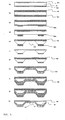
- Fig. 5 A method of creating the film holder 18 is next described by referring to Fig. 5 .
- Fig. 5 (a) silicon nitride films 502 and 503 are formed on a silicon substrate 501 using CVD (chemical vapor deposition). A typical thickness of the films 502 and 503 is 30 nm.
- Layers of resist 504 and 505 are applied on the silicon nitride films 502 and 503, respectively ( Fig. 5 (b) ).
- the layer of resist 505 is patterned photolithographically to leave behind resist layer portions 505a ( Fig. 5(c) ).
- the silicon nitride film 503 is processed by dry etching, and silicon nitride film portions 503a are left behind ( Fig. 5(d) ).
- the metal layer 507 is etched ( Fig. 5(j) ).
- the resist layer 508 is removed by ashing or organic cleaning ( Fig. 5 (k) ). As a result, the opening 34a and lattice 35 are formed.
- the film holder 18 fabricated in this way is inverted up and down from the state of Fig. 4 .
- the first surface 32a of the silicon nitride film 502 that is the sample-holding film 32 is taken as an upper surface.
- the second surface 32b can also be taken as an upper surface.
- the film holder 18 is firmly attached to the step portion 37c over the hole 37b formed in the body portion 37 forming the sample holder 40.
- the sample holder 40 is fabricated ( Fig. 3 ).
- bonding using an epoxy-based or silicone-based adhesive or fusion making use of heat, ultrasonic waves, or laser can be used. Consequently, the film holder 18 is firmly held in a position corresponding to the hole 37b in the sample-holding surface 37a of the body portion 37.
- the thickness of the silicon nitride film 502 is set to a range of from 10 to 1,000 nm.
- the sample-holding film 32 of the film holder 18 is made of silicon nitride.
- the film 32 may be made of siliconoxide, boronnitride, polymer, polyethylene, polyimide, polypropylene, or carbon. Where films of these materials are used, their film thicknesses are set to a range of from 10 to 1, 000 nm.
- the sample-holding film 32 made of the aforementioned material transmits the electron beam 7 but does not transmit gas or liquid. Moreover, it is highly desirable that the film be capable of withstanding a pressure difference of at least 1 atmosphere across the opposite surfaces.
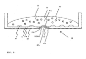
- FIG. 3 cells 38 to be inspected are cultured within a culture medium (reagent solution) 39 using the sample holder 40.
- a plugging agent 41 for example, made of polystyrene balls is put in the culture medium.
- the polystyrene balls are so large that they cannot pass through the cells in the lattice 35.
- the culture medium is Product No.
- the culture medium is discarded from the laboratory dish where the cells have been previously cultured.
- a mixture liquid of trypsin and EDTA ethylenediaminetetraacetic acid
- the peeled cells are recovered into a centrifuge tube.
- a culture medium is put into the tube.
- the trypsin is inactivated and then the cells are spun down.
- the supernatant fluid is discarded from the centrifuge tube and the remaining liquid is stirred in the culture medium.
- a part (e.g., 1/10) of the stirred liquid including the cells 38 is entered into the sample holder 40.
- the culture medium 39 is grafted.
- the holder is allowed to stand still in a cell culture chamber. After a lapse of several hours, the cells 38 begin to be adsorbed onto the sample-holding surface 37a of the sample holder 40 including the first surface 32a of the sample-holding film 32 and proliferate.
- the aforementioned method may be modified according to cells, and is merely one example. Consequently, the cells 38 to be observed or inspected are cultured within the sample holder 40. It follows that the liquid sample 20 containing the cultured cells 38 and culture medium 39 is constituted.
- the sample holder 40 After the cells are cultured within the sample holder 40 as described above, the sample holder 40 is placed on the holder placement portion 12. At this time, the open-close valve 14 is closed and in the state of Fig. 2 .
- the space 19a hermetically sealed between the valve 14 and the sample-holding film 32 is at a normal pressure, or in an atmospheric-pressure ambient. Within the vacuum chamber 11, the space located under the valve 14 is in a given vacuum state (reduced-pressure state).
- the positions of the sample cells 38 and of the manipulator 26 are checked with the optical microscope 27.
- a glass microtube holding microelectrodes therein is installed at the front end of the manipulator.
- a voltage can be applied to the cells through the microelectrodes.
- a liquid can be made to flow in and out through the glass microtube.
- the manipulator 26 is moved while making an observation with the optical microscope 27 to bring the cells 38 close to the glass microtube. Then, a negative pressure is applied to the glass microtube to bring it into intimate contact with the cell membranes. As a result, potential response can be measured.
- the particle 41a of the plugging agent 41 cannot pass through the cells formed by the frames of the lattice 35, if an external force is applied due to a pressure difference, the particle 41a of the plugging agent 41 does not intrude into the vacuum chamber 11.
- the plugging agent can be particulate plugging material such as polytetrafluoroethylene, latex, alumina, polystyrene, polymethyl methacrylate, silica, or glass.
- the particles can assume ball-like form. More preferably, the density of the plugging agent is higher than the density of the liquid sample by a factor of 0.9 to 1.1.
- the surface of the plugging agent is coated with a layer of a metal such as aluminum or gold.
- the metal layer can be formed on the surface of the plugging agent by a vacuum deposition technique.
- the surface of the plugging agent is coated with the metal layer, if the plugging agent is illuminated with an electron beam, charging of the plugging agent can be prevented. Consequently, when the sample is illuminated with an electron beam, charging of the plugging agent can be prevented; otherwise, charged particles of the plugging agent would move to the illuminated region, hindering observation of the sample. Hence, good observation of the sample can be made.
- the space 19a is in a reduced-pressure state or a vacuum state, it is checked that the sample-holding film 32 on which the sample 20 is placed is not destroyed. Then, the open-close valve 14 is opened. Thus, the space inside the vacuum chamber 11 is ceased to be partitioned to place the space located under the vacuum chamber 11 into communication with the space 19a. Thereafter, in order to prevent light from entering the backscattered electron detector 4 via the sample-holding film 32, the light illumination of the optical microscope 27 is ceased. Other extraneous light is blocked in a manner not shown. The blocking also shields the film holder 18 and liquid sample 20 against radiation rays produced when the electron beam 7 hits the film holder 18 and sample 20.
- the electron beam 7 is directed at the liquid sample 20 including the cells 38 from the electron optical column 1 to perform imaging.
- the beam 7 passes through the sample-holding film 32 of the sample holder 40 and hits the cells 38.
- Backscattered electrons produced from the cells 38 in response to the illumination are detected by the backscattered electron detector 4.
- the aforementioned tapering portions 37d are formed around the hole 37b of the body portion 37 forming the sample holder 40, collision of the backscattered electrons against the inner side surface of the hole 37b can be suppressed to a minimum. That is, the backscattered electrons can be suppressed frombeing blocked.
- the backscattered electrons can be detected efficiently by the backscattered electron detector 4.
- an electrical stimulus is given to the cells 38 using the microelectrodes installed at the front end of the manipulator 26.
- An SEM image is acquired in the same way as in the above-described process step. The response of the cells 38 to the stimulus is checked.
- the open-close valve 14 is closed to prevent contamination of the electron optical column 1 if the sample-holding film 32 should be destroyed.
- an observation may be made with the optical microscope 27.
- the open-close valve 14 is closed, risk of contamination occurring when the sample-holding film 32 is broken can be reduced.
- the probability of contamination of the inside of the apparatus can be reduced by shortening the interval for which the open-close valve 14 is opened during inspection.
- the open-close valve 14 may be once closed.
- the valve 14 may be again opened at a time when a reaction is deemed to have taken place.
- imaging may be performed using the electron beam 7.
- the reaction can be checked with the optical microscope 27.
- the manipulator 26 can have a mechanism capable of spraying a chemical substance or medicine into the liquid sample 20. Behavior of the cells 38 in response to the chemical substance or medicine can be observed or inspected while observing the cells by SEM. Furthermore, a function of permitting a liquid to flow out can be imparted to the manipulator 26. This permits the sprayed substance to be recovered. Also, the pH of the culture medium and the osmotic pressure can be maintained constant.
- backscattered electrons are used to form an image.
- Backscattered electrons produce a signal intensity proportional to the atomic number. Therefore, where the specimen is almost totally made of substances of low atomic numbers such as a biological specimen, the image contrast is very low, and it is difficult to improve the resolution.
- a heavy metal such as gold may be adsorbed onto portions of the cells 38 to be noticed in their behavior.
- gold is adsorbed onto the portions (antigen) via an antibody by causing the antigen tagged with gold particles having the nature of being adsorbed on the portions (antigen) to be sprayed against the cells by making use of an antigen-antibody reaction.
- a fluorescent dye or quantum dots e.g. , nanoparticles of Si or particles of CdSe coated with ZnS and having sizes of 10 to 20 nm
- emit light when irradiated with an electron beam may be previously adsorbed onto certain portions of the cells 38, and the emitted light may be observed with an optical microscope.
- normally used gold particles have particle diameters of 10 to 30 nm.
- the adsorptive force between the antibody and gold particles is weak, and gold particles of 10 to 30 nm may not be attached.
- very small gold particles nanogold particles having particle diameters of the order of nanometers are first attached to the antibody. Under this condition, the gold particles are too small and it is difficult to observe them by SEM.
- Silver is adsorbed around the gold particles by making use of a silver sensitizer. This makes it easier to detect them by SEM.
- cells previously cultured in a laboratory dish are taken out and grafted onto the sample holder 40. Then, the cells are cultured.
- cells may be taken from a living organism and directly placed on the sample-holding surface 37a of the sample holder 40. The cells may be cultured in the sample holder 40.
- the present invention makes it possible to observe or inspect a specimen via the sample-holding film 32, the specimen being included in a liquid and to be inspected.
- the use of an open sample chamber facilitates giving a stimulus to cells because access to the sample can be made from the outside.
- the amount of culture medium can be increased. Cells are allowed to survive for a long time.
- the plugging agent 41 consisting of particles having sizes capable of plugging up the gap is mixed in the liquid.
- the plugging agent 41 can plug up at least a part of the gap. Consequently, the amount of liquid flowing into the apparatus can be reduced. This makes it unnecessary to clean the inside of the apparatus if the sample-holding film 32 is destroyed 10 times. In addition, if the inside is cleaned, the amount of adhered contaminants is small. Hence, the cleaning can be done easily. In this way, the present invention enhances convenience in use of the apparatus.
- the plugging agent is made of polystyrene.
- the plugging agent may also be made of other substance such as polytetrafluoroethylene, latex, alumina, polymethyl methacrylate, silica, or glass.
- the density of the plugging agent is higher than the density of the liquid sample by a factor of 0.9 to 1.1 (more preferably 1.0 to 1.1)
- the plugging agent is suspended or settled in the liquid. If the sample-holding film is destroyed, the torn gap can be quickly plugged up. I f the plugging agent is too heavy, it takes a long time to move the plugging agent. If the plugging agent is too light, it is impossible to plug up the gap until the liquid is fully eliminated. Therefore, it is important to appropriately set the density.
- the concentration of particles of the plugging agent relative to the liquid sample is 0.001/ ⁇ l to 1/ ⁇ l , the observation is not hindered.
- the plugging agent is mixed, for example, in water, culture medium, or phosphate buffer, thus preparing a reagent for testing. It is expected that the aforementioned advantages can be obtained by adding the testing reagent to a liquid sample before observation.
- the sample cells 38 cultured on the sample holder 40 are observed through the cells in the lattice 35.
- Biological cells have sizes of 10 to hundreds of micrometers.
- the lattice spacing that provides easy observation as estimated from the sizes of sample cells is 10 to 500 ⁇ m. Therefore, if the maximum length of particles of the plugging agent is set according to the lattice interval, i.e., 10 to 500 ⁇ m, the born gap in the sample-holding film 32 can be plugged up efficiently.
- an electron beam is used as the primary beam. If the sample-holding film 32 shows sufficient shock resistance and strength against impingement of other charged particle beam such as a helium ion beam, the invention can also be applied in a case where the other charged particle beam is used.
- backscattered electrons are used as a secondary signal.
- Information about the cells 38 can also be obtained by detecting other form of information such as secondary electrons, X-rays, cathodoluminescent light, and electric current absorbed into the cells 38 to be inspected. It is convenient to use the manipulator 26 in measuring the absorption current.
- the inspection method comprises the steps of: holding the sample 20 on the first surface of the film 32 disposed on the frame-like member 18 having the opening 34a, the opening 34a of the frame-like member 18 being covered with the film 32, the sample 20 containing the specimen 38 to be inspected, and the reagent solution 39 holding the specimen 38; mixing the plugging agent 41 consisting of particles having sizes capable of plugging up at least a part of the opening 34a into the reagent solution 39; directing a primary beam at the sample 20 via the film 32 from the second surface of the film 32; and detecting a secondary signal produced from the sample 20 in response to the primary beam irradiation.
- the frame-like member 18 has a lattice structure inside the opening 34a.
- the particles of the plugging agent 41 can plug up at least some of the cells in the lattice structure.
- the particles of the plugging agent 41 can have sizes not passing through the cells inside the lattice structure.
- the primary beam can be an electron beam or an ion beam.
- the secondary signal can be any one type of backscattered electrons, secondary electrons, X-rays, cathodoluminescent light, and absorption current.
- the first surface of the film 32 can be taken as an upper surface and the second surface of the film 32 can be taken as a lower surface.
- the reagent solution according to the present invention is used to hold the specimen 38 when it is inspected by irradiating it with a primary beam via the film 32 that covers the opening 34a in the frame-like member 18.
- the plugging agent 41 consisting of particles having sizes capable of plugging up at least a part of the opening 34a is mixed in the reagent solution.
- the maximum length of the particles of the plugging agent 41 described above can be set to a range of 10 ⁇ m to 500 ⁇ m.
- the plugging agent 41 can be made of polytetrafluoroethylene, latex, alumina, polystyrene, polymethyl methacrylate, silica, or glass.
- the surface of the plugging agent 41 can be coated with a metal layer.
- the density of the plugging agent 41 can be set higher than the density of the liquid component of the reagent solution 39 by a factor of 0.9 to 1.1.
- the concentration of particles of the plugging agent 41 in the reagent solution 39 can be set to a range of 0.001/ ⁇ l to 1/ ⁇ l .
Landscapes
- Chemical & Material Sciences (AREA)
- Analytical Chemistry (AREA)
- Physics & Mathematics (AREA)
- Health & Medical Sciences (AREA)
- Life Sciences & Earth Sciences (AREA)
- Biochemistry (AREA)
- General Health & Medical Sciences (AREA)
- General Physics & Mathematics (AREA)
- Immunology (AREA)
- Pathology (AREA)
- Analysing Materials By The Use Of Radiation (AREA)
- Apparatus Associated With Microorganisms And Enzymes (AREA)
Applications Claiming Priority (1)
| Application Number | Priority Date | Filing Date | Title |
|---|---|---|---|
| JP2008099856A JP5314317B2 (ja) | 2008-04-08 | 2008-04-08 | 検査方法及び試液 |
Publications (3)
| Publication Number | Publication Date |
|---|---|
| EP2108946A2 true EP2108946A2 (de) | 2009-10-14 |
| EP2108946A3 EP2108946A3 (de) | 2011-03-16 |
| EP2108946B1 EP2108946B1 (de) | 2013-02-20 |
Family
ID=40934940
Family Applications (1)
| Application Number | Title | Priority Date | Filing Date |
|---|---|---|---|
| EP20080254161 Ceased EP2108946B1 (de) | 2008-04-08 | 2008-12-24 | Prüfverfahren und Reagenzlösung |
Country Status (3)
| Country | Link |
|---|---|
| US (1) | US7906760B2 (de) |
| EP (1) | EP2108946B1 (de) |
| JP (1) | JP5314317B2 (de) |
Cited By (1)
| Publication number | Priority date | Publication date | Assignee | Title |
|---|---|---|---|---|
| CN106770405A (zh) * | 2016-12-09 | 2017-05-31 | 清华大学 | 一种完全大气压下超光学衍射成像装置 |
Families Citing this family (8)
| Publication number | Priority date | Publication date | Assignee | Title |
|---|---|---|---|---|
| EP1936363A3 (de) * | 2006-12-19 | 2010-12-08 | JEOL Ltd. | Vorrichtung, Verfahren und System zur Probenuntersuchung |
| JP5318364B2 (ja) * | 2007-01-31 | 2013-10-16 | 日本電子株式会社 | 試料保持体、試料検査装置及び試料検査方法、並びに試料保持体の製造方法 |
| JP2010002300A (ja) * | 2008-06-20 | 2010-01-07 | Jeol Ltd | 試料保持体、試料検査装置及び試料検査方法 |
| US10505234B2 (en) | 2011-03-14 | 2019-12-10 | Battelle Memorial Institute | Battery cell and n situ battery electrode analysis method |
| US10598609B2 (en) | 2011-03-14 | 2020-03-24 | Battelle Memorial Institute | Universal liquid sample device and process for high resolution transmission electron microscope imaging and multimodal analyses of liquid sample materials |
| US9274059B2 (en) | 2011-03-14 | 2016-03-01 | Battelle Memorial Institute | Microfluidic electrochemical device and process for chemical imaging and electrochemical analysis at the electrode-liquid interface in-situ |
| TWI472751B (zh) * | 2011-05-03 | 2015-02-11 | Hermes Microvision Inc | 用於檢查與複檢光罩/晶圓缺陷的帶電粒子系統 |
| JP6796611B2 (ja) * | 2018-03-26 | 2020-12-09 | 日本電子株式会社 | 液体試料を観察または分析する方法および電子顕微鏡 |
Citations (3)
| Publication number | Priority date | Publication date | Assignee | Title |
|---|---|---|---|---|
| JPH06318445A (ja) | 1993-01-18 | 1994-11-15 | Tanpaku Kogaku Kenkyusho:Kk | 電子顕微鏡等の試料ホルダ |
| JP2004515049A (ja) | 2000-12-01 | 2004-05-20 | エダ リサーチ アンド ディベロップメント カンパニー,リミティド | 走査型電子顕微鏡を用いた非真空環境内のサンプルの検査のための装置および方法 |
| JP2007292702A (ja) | 2006-04-27 | 2007-11-08 | Jeol Ltd | 試料検査装置及び試料検査方法並びに試料検査システム |
Family Cites Families (6)
| Publication number | Priority date | Publication date | Assignee | Title |
|---|---|---|---|---|
| JPS4724961U (de) | 1971-04-14 | 1972-11-20 | ||
| EP0339980B1 (de) * | 1988-04-26 | 1994-07-20 | Nippon Telegraph And Telephone Corporation | Mikropartikel, Verfahren und Gerät zur Sammlung von Proben zur Verwendung bei der Markierung von Immunreaktionen und Verfahren und Gerät zur Bereitung von Proben |
| JP3359703B2 (ja) * | 1992-08-27 | 2002-12-24 | オリンパス光学工業株式会社 | X線顕微鏡用試料容器及び試料保持方法 |
| DE10064827A1 (de) * | 2000-12-22 | 2002-06-27 | Dade Behring Marburg Gmbh | Nachweisverfahren |
| US6777674B2 (en) * | 2002-09-23 | 2004-08-17 | Omniprobe, Inc. | Method for manipulating microscopic particles and analyzing |
| JP2007294365A (ja) * | 2006-04-27 | 2007-11-08 | Jeol Ltd | 試料検査方法、試料保持体、及び試料検査装置並びに試料検査システム |
-
2008
- 2008-04-08 JP JP2008099856A patent/JP5314317B2/ja not_active Expired - Fee Related
- 2008-12-15 US US12/335,143 patent/US7906760B2/en not_active Expired - Fee Related
- 2008-12-24 EP EP20080254161 patent/EP2108946B1/de not_active Ceased
Patent Citations (3)
| Publication number | Priority date | Publication date | Assignee | Title |
|---|---|---|---|---|
| JPH06318445A (ja) | 1993-01-18 | 1994-11-15 | Tanpaku Kogaku Kenkyusho:Kk | 電子顕微鏡等の試料ホルダ |
| JP2004515049A (ja) | 2000-12-01 | 2004-05-20 | エダ リサーチ アンド ディベロップメント カンパニー,リミティド | 走査型電子顕微鏡を用いた非真空環境内のサンプルの検査のための装置および方法 |
| JP2007292702A (ja) | 2006-04-27 | 2007-11-08 | Jeol Ltd | 試料検査装置及び試料検査方法並びに試料検査システム |
Cited By (1)
| Publication number | Priority date | Publication date | Assignee | Title |
|---|---|---|---|---|
| CN106770405A (zh) * | 2016-12-09 | 2017-05-31 | 清华大学 | 一种完全大气压下超光学衍射成像装置 |
Also Published As
| Publication number | Publication date |
|---|---|
| EP2108946B1 (de) | 2013-02-20 |
| JP5314317B2 (ja) | 2013-10-16 |
| US7906760B2 (en) | 2011-03-15 |
| JP2009250813A (ja) | 2009-10-29 |
| US20090250609A1 (en) | 2009-10-08 |
| EP2108946A3 (de) | 2011-03-16 |
Similar Documents
| Publication | Publication Date | Title |
|---|---|---|
| EP2312302A1 (de) | Vorrichtung und Verfahren zur Untersuchung von Proben | |
| US8119994B2 (en) | Apparatus and method for inspecting sample | |
| EP2108946B1 (de) | Prüfverfahren und Reagenzlösung | |
| US7745802B2 (en) | Specimen holder, specimen inspection apparatus, specimen inspection method, and method of fabricating specimen holder | |
| US8030622B2 (en) | Specimen holder, specimen inspection apparatus, and specimen inspection method | |
| EP2388575A1 (de) | Probenhalter, Untersuchungsvorrichtung und Untersuchungsverfahren | |
| US7968843B2 (en) | Method and apparatus for simultaneous SEM and optical examination | |
| JP4153303B2 (ja) | 走査型電子顕微鏡を用いた非真空環境内のサンプルの検査のための装置および方法 | |
| US7928380B2 (en) | Sample holder, method for observation and inspection, and apparatus for observation and inspection | |
| AU2002221019A1 (en) | Device and method for the examination of samples in a non-vacuum environment using a scanning electron microscope | |
| EP2148359A2 (de) | Probenhalter, Probenprüfvorrichtung und Probenprüfverfahren | |
| EP1953793B1 (de) | Probenhalter, Probenprüfvorrichtung, Probenprüfverfahren und Verfahren zur Herstellung des Probenhalters |
Legal Events
| Date | Code | Title | Description |
|---|---|---|---|
| PUAI | Public reference made under article 153(3) epc to a published international application that has entered the european phase |
Free format text: ORIGINAL CODE: 0009012 |
|
| AK | Designated contracting states |
Kind code of ref document: A2 Designated state(s): AT BE BG CH CY CZ DE DK EE ES FI FR GB GR HR HU IE IS IT LI LT LU LV MC MT NL NO PL PT RO SE SI SK TR |
|
| AX | Request for extension of the european patent |
Extension state: AL BA MK RS |
|
| PUAL | Search report despatched |
Free format text: ORIGINAL CODE: 0009013 |
|
| AK | Designated contracting states |
Kind code of ref document: A3 Designated state(s): AT BE BG CH CY CZ DE DK EE ES FI FR GB GR HR HU IE IS IT LI LT LU LV MC MT NL NO PL PT RO SE SI SK TR |
|
| AX | Request for extension of the european patent |
Extension state: AL BA MK RS |
|
| 17P | Request for examination filed |
Effective date: 20110916 |
|
| 17Q | First examination report despatched |
Effective date: 20111021 |
|
| AKX | Designation fees paid |
Designated state(s): CH DE FR GB LI |
|
| GRAP | Despatch of communication of intention to grant a patent |
Free format text: ORIGINAL CODE: EPIDOSNIGR1 |
|
| GRAS | Grant fee paid |
Free format text: ORIGINAL CODE: EPIDOSNIGR3 |
|
| GRAA | (expected) grant |
Free format text: ORIGINAL CODE: 0009210 |
|
| AK | Designated contracting states |
Kind code of ref document: B1 Designated state(s): CH DE FR GB LI |
|
| REG | Reference to a national code |
Ref country code: GB Ref legal event code: FG4D |
|
| REG | Reference to a national code |
Ref country code: CH Ref legal event code: EP Ref country code: CH Ref legal event code: NV Representative=s name: KIRKER AND CIE S.A., CH |
|
| REG | Reference to a national code |
Ref country code: DE Ref legal event code: R096 Ref document number: 602008022270 Country of ref document: DE Effective date: 20130418 |
|
| PLBE | No opposition filed within time limit |
Free format text: ORIGINAL CODE: 0009261 |
|
| STAA | Information on the status of an ep patent application or granted ep patent |
Free format text: STATUS: NO OPPOSITION FILED WITHIN TIME LIMIT |
|
| 26N | No opposition filed |
Effective date: 20131121 |
|
| REG | Reference to a national code |
Ref country code: DE Ref legal event code: R097 Ref document number: 602008022270 Country of ref document: DE Effective date: 20131121 |
|
| REG | Reference to a national code |
Ref country code: FR Ref legal event code: PLFP Year of fee payment: 8 |
|
| REG | Reference to a national code |
Ref country code: FR Ref legal event code: PLFP Year of fee payment: 9 |
|
| REG | Reference to a national code |
Ref country code: FR Ref legal event code: PLFP Year of fee payment: 10 |
|
| PGFP | Annual fee paid to national office [announced via postgrant information from national office to epo] |
Ref country code: GB Payment date: 20211222 Year of fee payment: 14 Ref country code: FR Payment date: 20211224 Year of fee payment: 14 Ref country code: DE Payment date: 20211210 Year of fee payment: 14 |
|
| PGFP | Annual fee paid to national office [announced via postgrant information from national office to epo] |
Ref country code: CH Payment date: 20211221 Year of fee payment: 14 |
|
| REG | Reference to a national code |
Ref country code: DE Ref legal event code: R119 Ref document number: 602008022270 Country of ref document: DE |
|
| REG | Reference to a national code |
Ref country code: CH Ref legal event code: PL |
|
| GBPC | Gb: european patent ceased through non-payment of renewal fee |
Effective date: 20221224 |
|
| PG25 | Lapsed in a contracting state [announced via postgrant information from national office to epo] |
Ref country code: LI Free format text: LAPSE BECAUSE OF NON-PAYMENT OF DUE FEES Effective date: 20221231 Ref country code: GB Free format text: LAPSE BECAUSE OF NON-PAYMENT OF DUE FEES Effective date: 20221224 Ref country code: DE Free format text: LAPSE BECAUSE OF NON-PAYMENT OF DUE FEES Effective date: 20230701 Ref country code: CH Free format text: LAPSE BECAUSE OF NON-PAYMENT OF DUE FEES Effective date: 20221231 |
|
| PG25 | Lapsed in a contracting state [announced via postgrant information from national office to epo] |
Ref country code: FR Free format text: LAPSE BECAUSE OF NON-PAYMENT OF DUE FEES Effective date: 20221231 |