EP2108929B1 - Steuerungsverfahren und -vorrichtung zum kochen von lebensmitteln - Google Patents
Steuerungsverfahren und -vorrichtung zum kochen von lebensmitteln Download PDFInfo
- Publication number
- EP2108929B1 EP2108929B1 EP08718438.8A EP08718438A EP2108929B1 EP 2108929 B1 EP2108929 B1 EP 2108929B1 EP 08718438 A EP08718438 A EP 08718438A EP 2108929 B1 EP2108929 B1 EP 2108929B1
- Authority
- EP
- European Patent Office
- Prior art keywords
- food
- temperature
- cooking
- thickness
- time
- Prior art date
- Legal status (The legal status is an assumption and is not a legal conclusion. Google has not performed a legal analysis and makes no representation as to the accuracy of the status listed.)
- Not-in-force
Links
- 235000013305 food Nutrition 0.000 title claims description 342
- 238000010411 cooking Methods 0.000 title claims description 180
- 238000000034 method Methods 0.000 title claims description 77
- 238000001514 detection method Methods 0.000 claims description 68
- 230000008569 process Effects 0.000 claims description 33
- 238000010521 absorption reaction Methods 0.000 claims description 26
- 230000007306 turnover Effects 0.000 claims description 23
- 241001631457 Cannula Species 0.000 claims description 22
- 238000012545 processing Methods 0.000 claims description 19
- 238000010438 heat treatment Methods 0.000 claims description 18
- 230000001427 coherent effect Effects 0.000 claims description 14
- 238000003780 insertion Methods 0.000 claims description 14
- 230000037431 insertion Effects 0.000 claims description 14
- 230000005540 biological transmission Effects 0.000 claims description 12
- 230000007246 mechanism Effects 0.000 claims description 11
- 238000012937 correction Methods 0.000 claims description 6
- XLYOFNOQVPJJNP-UHFFFAOYSA-N water Substances O XLYOFNOQVPJJNP-UHFFFAOYSA-N 0.000 claims description 5
- 230000007423 decrease Effects 0.000 claims description 4
- 238000011156 evaluation Methods 0.000 claims description 3
- 239000000835 fiber Substances 0.000 claims description 3
- 238000002604 ultrasonography Methods 0.000 claims description 3
- 230000003247 decreasing effect Effects 0.000 claims description 2
- 238000004886 process control Methods 0.000 claims description 2
- 239000000523 sample Substances 0.000 description 69
- 230000001276 controlling effect Effects 0.000 description 14
- 230000008859 change Effects 0.000 description 6
- 238000000926 separation method Methods 0.000 description 6
- 239000007788 liquid Substances 0.000 description 5
- 238000002360 preparation method Methods 0.000 description 3
- 235000013372 meat Nutrition 0.000 description 2
- 230000001105 regulatory effect Effects 0.000 description 2
- 241000251468 Actinopterygii Species 0.000 description 1
- 230000003213 activating effect Effects 0.000 description 1
- 238000009529 body temperature measurement Methods 0.000 description 1
- 239000003610 charcoal Substances 0.000 description 1
- 230000001143 conditioned effect Effects 0.000 description 1
- 238000001704 evaporation Methods 0.000 description 1
- 230000008020 evaporation Effects 0.000 description 1
- 238000013213 extrapolation Methods 0.000 description 1
- 239000012530 fluid Substances 0.000 description 1
- 235000015219 food category Nutrition 0.000 description 1
- 235000011194 food seasoning agent Nutrition 0.000 description 1
- 230000005484 gravity Effects 0.000 description 1
- -1 infrared Substances 0.000 description 1
- 238000005259 measurement Methods 0.000 description 1
- 238000012986 modification Methods 0.000 description 1
- 230000004048 modification Effects 0.000 description 1
- 230000009467 reduction Effects 0.000 description 1
- 230000000717 retained effect Effects 0.000 description 1
- 238000012546 transfer Methods 0.000 description 1
- 230000004580 weight loss Effects 0.000 description 1
Images


Classifications
-
- A—HUMAN NECESSITIES
- A47—FURNITURE; DOMESTIC ARTICLES OR APPLIANCES; COFFEE MILLS; SPICE MILLS; SUCTION CLEANERS IN GENERAL
- A47J—KITCHEN EQUIPMENT; COFFEE MILLS; SPICE MILLS; APPARATUS FOR MAKING BEVERAGES
- A47J27/00—Cooking-vessels
- A47J27/56—Preventing boiling over, e.g. of milk
- A47J27/62—Preventing boiling over, e.g. of milk by devices for automatically controlling the heat supply by switching off heaters or for automatically lifting the cooking-vessels
-
- G—PHYSICS
- G01—MEASURING; TESTING
- G01K—MEASURING TEMPERATURE; MEASURING QUANTITY OF HEAT; THERMALLY-SENSITIVE ELEMENTS NOT OTHERWISE PROVIDED FOR
- G01K1/00—Details of thermometers not specially adapted for particular types of thermometer
- G01K1/02—Means for indicating or recording specially adapted for thermometers
- G01K1/026—Means for indicating or recording specially adapted for thermometers arrangements for monitoring a plurality of temperatures, e.g. by multiplexing
-
- G—PHYSICS
- G01—MEASURING; TESTING
- G01K—MEASURING TEMPERATURE; MEASURING QUANTITY OF HEAT; THERMALLY-SENSITIVE ELEMENTS NOT OTHERWISE PROVIDED FOR
- G01K1/00—Details of thermometers not specially adapted for particular types of thermometer
- G01K1/14—Supports; Fastening devices; Arrangements for mounting thermometers in particular locations
-
- G—PHYSICS
- G01—MEASURING; TESTING
- G01K—MEASURING TEMPERATURE; MEASURING QUANTITY OF HEAT; THERMALLY-SENSITIVE ELEMENTS NOT OTHERWISE PROVIDED FOR
- G01K2207/00—Application of thermometers in household appliances
- G01K2207/02—Application of thermometers in household appliances for measuring food temperature
- G01K2207/06—Application of thermometers in household appliances for measuring food temperature for preparation purposes
Definitions
- the present invention relates to a food cooking control method and device.
- the invention is particularly applicable to a food cooking process on a surface such as a griddle during which the food will be turned several times.
- the proposed device can be associated to another piece of equipment or machine used to manage food finishing.
- Food cooking control devices are known the aim of which is to facilitate and standardize food preparation without needing to have specialized labor. These devices consist of elements equipped with cannulas or rods provided with temperature detectors which are inserted into the food to be controlled. The element is usually connected to means for processing the information received from the detectors, such that food cooking is controlled according to certain parameters.
- the different devices have a common element, all of them are inserted into the food but lack means for determining the exact position of the device inside the food. Since the exact position of the temperature sensors inside the food is not known, it is not possible for them to control the energy accumulated in the temperature gradient occurring between the outer area of the food through which it receives heat and the center of the food while it is cooked. Nevertheless this energy accumulated in the gradient between the inside and the outside will appear when the cooking ends and the supply of energy maintaining the gradient ceases. The energy accumulated in the gradient will diffuse until equilibrium is reached and the temperature in the entire piece becomes equal.
- United States patent no. US 6753027 describes a method for controlling the cooking process and a detector for carrying out said method.
- a detector for carrying out said method.
- at least two temperature values are obtained by means of a detector adapted to be at least partially stuck into the food to be cooked.
- Said temperature values are obtained at several points in random positions inside the food at different depths, the separation distances between the detection points being fixed and known, and at least at another point outside the food determining the temperature of the environment.
- the drawback of the described method is that the temperature detector is stuck in a different way inside the food every time it is used, such that the points at which the temperature is measured are different for each use.
- the separation distance between the different detection points is known, it is not possible to know the relative position thereof inside the food. This makes it impossible to position the detection points in the most interesting precise zones to control the food temperature.
- the temperature taking points are positioned in a substantially different manner in relation to the thickness of each food, which makes the data obtained useless.
- This drawback is more obvious in foods which are semi-submersed in liquids, or in foods receiving heat through only one side.
- the described method does not allow applying uniform cooking parameters giving the same result for all the foods in which it is used, since the temperature values taken for a food correspond to zones different from those controlled in another food.
- Patent DE-A-4032949 describes a device proposing the use of two temperature sensors, one for being positioned on the surface of the food and the other one inside such food which can be stuck at greater or lesser depth into the food but without precision or control.
- European patent EP 1473554 describes a utensil and a method for controlling a cooking device.
- This utensil consists of a temperature measurement device with two temperature detectors. One of said detectors is at one end of the utensil in contact with the bottom of a cooking receptacle, and the other device is positioned at a certain distance from said end.
- This utensil allows controlling the temperature of the cooking receptacle and of the cooked food. Nevertheless, the described utensil has the drawback that it only allows controlling points positioned at fixed and determined distances from the food. If the size of the different foods changes, or the utensil is placed differently, the detectors of the utensil are positioned at different points or even outside the food. Furthermore, it must be added that most foods change in shape and/or geometry during the cooking process, which makes their use be limited to controlling the cooking of regular liquids or foods with constant thickness and which do not change in geometry during the cooking process.
- the temperature detector in contact with the bottom of the receptacle may not be very useful, since the heat supplied to the food is transmitted in a different manner according to the characteristics of the food to be controlled and the heat source.
- patent EP 1688721B1 describes a method for determining the turn-over time of a food. Said method only refers to the first turn-over of the food and calculates the time in which it is carried out according to the different between the final temperature and the initial temperature of the food.
- the present invention relates to a food cooking process control method according to claim 1, comprising the insertion inside a food, for example a piece of meat or fish, supported on a reference surface or cooking surface (e.g. a griddle), of one or more temperature detection devices.
- a food for example a piece of meat or fish
- a reference surface or cooking surface e.g. a griddle
- a basic version of the proposed method comprises:
- Said pre-determined zone of the food is generally a middle or central zone in relation to the total or absolute thickness of the food.
- the method further proposes, by means of the aid of positioning means which allow positioning probes on the surface or at exact known depths inside the food with respect to it limits, determining and processing the temperature of the surface through which the food receives heat or a temperature close to the cooking surface detected TP.
- the method is thus implemented with a joint processing of said temperature TP and temperature TC in addition to a permanent evaluation of the variation of said temperature TC to the first derivative level.
- An evaluation of the variation of the first derivative of said temperature TC is also generally proposed.
- the method of the present invention further comprises:
- said desired equilibrium food temperature is an equilibrium temperature in said middle or central zone, which is the target upon ending the cooking and taking into account a subsequent food transfer on a known mass consumption surface and at a given temperature.
- TCC TC + TP ⁇ TC XF + D 1 + D 2
- Factor F furthermore depends on the interrelation between the derivative of the temperature TC or slope PC and the derivative of the temperature TP or slope PP, such that when the relation between TP and TC reaches certain values, the coefficient F changes. Said variation is mainly due to factors which alter the energy absorbed by the food, such as the mass loss and the evaporation of the water from the surface of the food, as well as to the internal transmission of heat due to the water which is retained between the fibers and moved by capillarity, transmitting the heat inside the food, substantially modifying the heat transmission inside the food.
- the method comprises the insertion in the food of at least two of said temperature detection devices by means of the aid of said positioning means, to an absolute pre-determined distance with respect to said reference surface and controlling the temperature and evolution of temperature of each of said detection devices, one of which provides the aforementioned temperature TC.
- the method likewise comprises the detection of the temperature of said cooking surface of the food and/or the detection of the room temperature and/or the detection of the temperature close to a zone of the food by means of at least one temperature detection device.
- the method is implemented in practice by means of the control of a food cooking device according to the processed data, at least in relation to temperature, and to pre-determined cooking parameters.
- said cooking surface is obtained by applying a heat source placed under said food, such as a hot plate, on which the food directly rests.
- the method comprises analyzing with a certain frequency the data or readings from said temperature detection devices to know the detected central temperature TC of the food over time, and comparing said values of the detected central temperature TC with the value of a target central temperature TCO, predefined by the user depending on the cooking point required for the food, controlling said heat source according to the result of said comparisons.
- the method of the present invention also comprises measuring the elapsed time between said application of said heat source under the food and the time at which said signal has been generated and once said food has been turned over, maintaining the application of said heat source under the food during an application time depending on said measured time.
- the method comprises controlling said heat source to apply a different heating power during the measured time before turning the food over and during the application time once the food has been turned over.
- Said heat source is controlled by means of a series of predefined successive increments of the heating power taking into account an initial central temperature TCI of the food.
- the method also comprises analyzing the variation of said values of the detected central temperature TC over time to establish:
- the method comprises considering the results of said comparisons of the detected central temperature TC with the target central temperature TCO as invalid until it is established that the evolution is coherent.
- the method likewise comprises calculating a function of the calculated target central temperature TCCO of the food defined as the target central temperature TCO plus a safety factor due to the heat loss experienced in the food when it is removed from the heat source and placed on a surface at a lower temperature. In the event that the surface on which the food is placed is at temperature TCO, then TCCO and TCO would coincide.
- the method proposes determining for a given food a function reflecting the optimal heat absorption coefficients P optimal for each detected temperature close to the cooking surface TP. Tolerance ranges for the maximum and minimum absorption coefficients are fixed for each temperature based on these optimal functions.
- the functions mark the maximum and minimum heat absorption coefficients the food can have for each temperature of the cooking process, i.e., how many degrees centigrade the surface of the food can increase per second.
- the mentioned functions are conditioned by the characteristics of the cooking element, the heat transmission capacity, its heating power and its thermal inertia on one hand and by the characteristics of the food on the other.
- the calculated heat absorption coefficient function of the food with respect to time is at least one slope function PP obtained as a result of the evolution of the values of the detected temperature close to the cooking surface TP over time.
- said calculated heat absorption coefficient function of the food with respect to the time is an average function PPM of said slope function PP obtained as a result of the evolution of the values of the detected temperature close to the cooking surface TP over time.
- the system thus compares during the entire cooking time the average function PPM to the optimal heat absorption coefficient P optimal . Therefore, in the event that the average function PPM is greater than the maximum heat absorption coefficient for a certain number of readings, the system sends a signal so that the heating power is reduced, since the temperature increment that is occurring exceeds what is necessary. In addition, when the average function PPM is less than the minimum heat absorption coefficient, the system at first sends a probe repositioning signal, since foods deform during the cooking process and it is necessary to reposition the probe in the pre-determined point close to the griddle. If after repositioning the average function PPM continues to be greater than said maximum heat absorption coefficient function, the system sends a signal so that the heating power is increased, since the temperature increment that is occurring is less than what is necessary.
- the method comprises indicating that the food is cooked.
- the method comprises indicating that the food is cooked.
- the method comprises indicating that the food is cooked.
- the present invention relates to a food cooking control device according to claim 10, comprising at least one adapted detection device intended to be inserted in the food.
- the device further comprises means for determining the thickness of the food and positioning means for positioning said detection device inside said food to a pre-determined insertion depth in relation to the thickness of the food.
- the positioning means comprise cannulas which are inserted transversely into the food, and in which the detection devices are assembled.
- the device includes two of said detection devices, the positioning means being adapted to position one of said detection devices at an absolute pre-determined distance with respect to a reference surface on which the food is supported or the upper movable stop or both, said pre-determined distance preferably being between 0.5 and 30 mm, and more preferably between 1 and 10 mm.
- these means comprise a reference element to be supported by an end on said reference surface on which the food is supported and a stop movable with respect to said reference element to be supported on the surface of the food opposite to the reference surface, the thickness of the food being determined by the distance between said stop supported on the surface of the food and the end of said reference element.
- the means for determining the thickness of the food comprise an electronic measuring apparatus with a detector device suitable for detecting said thickness without contact with the food, said detector device comprising at least an emitter and a receiver of, for example, microwaves or of ultrasounds, the positioning means being adapted to individually position each detection device inside the food according to the thickness of the food detected by the electronic measuring apparatus.
- the detection devices are temperature detection devices, although for other embodiments the detection devices are devices of the group comprising: temperature detection devices, detection devices for detecting moisture, electric conductivity, distance and pH, or a combination thereof.
- each detector device can be positioned at the most interesting points throughout the thickness of the food to control the temperature thereof when the detector devices are temperature detectors or probes.
- the latter comprises for another embodiment a detection device for detecting the room temperature and/or a detection device for detecting the of the temperature of one or more surfaces of the food and/or a detection device for detecting the temperature of the reference surface when it is a cooking surface, such as an infrared temperature probe which allows measuring either the temperature of the surface of the food or of the cooking surface during the cooking process or before said process begins.
- the device is communicated with an electronic system with processing means, in connection with said detection devices and/or said detection devices for detecting room temperature and/or the temperature of the surface of the food and/or said means for determining the thickness of the food, to at least process data received from said devices or means and/or to store records of said data.
- Said electronic system comprises indicators, and is adapted to activate said indicators when the detected temperatures reach certain values and/or when said values are maintained for a certain time.
- the proposed device is applicable to cooking a food supported on a cooking surface to which a constant heating power or a heating power not controlled by the device is applied
- the use of the proposed device to control said heating power to be applied is contemplated, to which end said electronic system comprises means for control associated to said processing means, to control a cooking device for cooking the food according to the processed data and with pre-determined and/or programmable cooking parameters.
- the processing means comprise means for providing cooking instructions for cooking the food according to the processed data, so that for example a user can follow them appropriately to cook the food according to a cooking program.
- the device is autonomous, comprising the mentioned electronic system, and for another embodiment the device does not comprise the electronic system (or it comprises only one part), but rather is connected with said system, which (at least one part) forms part of said cooking device, such as a Clamshell griddle or a cooking tunnel, the device being able to be integrated inside said machines.
- the device of the invention allows precisely controlling, even on a large scale, cooking food.
- the simpler designs of the device of the invention could consist of indicators associated to the detector devices which are activated when the cooking has reached the desired point, such as in the mentioned case of an autonomous device.
- said means could consist of a desktop computer or laptop, an electronic agenda adapted to the device, etc. Programs adapted to each type of food or to each particular taste could be created. As a result of this configuration, cooking foods could be done completely autonomously since the device takes care of regulating the amount of heat supplied to each food and even the time at which it is turned off.
- the positioning means of the proposed device are adapted to reposition them against changes in the thickness and/or shape of the food while cooking, maintaining the relative positions with respect to the new thickness and/or new shape of the food.
- the positioning means comprise an anchor intended to be fixed to the surface or zone of the food closest to said support surface.
- the positioning means comprise a thrust device arranged to thrust, in the use position, said stop towards the food so that in the event that the food decreases in thickness or changes regarding the surface profile, the stop changes its position until coming in to contact with the surface of the food opposite to the reference surface, for the purpose of determining the new thickness of the food to reposition the detector devices.
- said thrust device is a spring, and for another embodiment, said thrust device is actuated by an electric motor.
- Said thrust element is not necessary for the case in which the stop, or an element attached thereto, weighs enough so as to exert sufficient force against the food to reposition itself, and with it the detectors, when the food decreases in thickness.
- the positioning means comprise one electric motor for every detection device in order to deal with said changes in the thickness and/or shape of the food during cooking, thus maintaining the relative positions with respect to the new thickness and/or new shape of the food by means of the individualized movement of each detector.
- the positioning means are completely automatic, including the energy supply, not requiring the intervention of the user, such as would be the case for example in which the device is moved by a robotic arm.
- the positioning means require human intervention at least for an initial movement of the device until arranging them on the food and/or to move the detectors to inside the food.
- the detector devices are temperature probes
- the interval of distances between them allows, by means of the probe located in the zone inside the food closest to a cooking surface, tracking the heat absorbed by the food and immediately knowing if the food is burning, since this zone is the one receiving the most heat.
- the probe is separated from said cooking surface such that distortions that would be generated if the probe was in direct contact with said surface are avoided.
- the ends of the cannulas with a pointed shape facilitate the insertion thereof in the food.
- the pointed shape also prevents the heat transmission towards the probe from being more than desired.
- the reference surface is preferably a cooking surface on which the food is supported, the surface could be any fixed point outside with respect to which one of the detector devices could be positioned inside the food.
- the device of the invention is especially useful for any type of foods cooked on a griddle or grill, which are usually the most difficult foods to control.
- the device 1 of the invention preferably consists of a plurality of detection devices, preferably temperature detection devices or probes 2a, 2b, 2c which are assembled in parallel cannulas 3a, 3b, 3c. These probes 2a, 2b, 2c are connected to means for processing the data received therefrom, which will be described below.
- the cannulas 3a, 3b, 3c are intended to be inserted transversely by sticking them inside food for the purpose of controlling the cooking thereof.
- the minimum number of probes 2a, 2b, 2c for the device to work is one, but their number may vary according to needs; in the depicted embodiment, the device 1 comprises 3 probes.
- the cannulas 3a, 3b, 3c can be moved longitudinally with respect to a stop 4, the function of which will also be explained below.
- the cannulas 3a, 3b, 3c are associated to the stop 4 by means of a transmission mechanism (not shown) which allows changing the distance between the stop 4 and the probes 2a, 2b, 2c of each cannula 3a, 3b, 3c proportionally.
- This mechanism which can be any mechanism which allows changing the relation between the movement of each of the cannulas 3a, 3b, 3c, such as for example a gear or pulleys, allows the movement of each of the cannulas 3a, 3b, 3c to be proportional to that of the others.
- a device 1 ( Figures 2 and 3 ) can thus be provided which allows extending the free end of the cannula 3a to a desired distance A from the stop 4, the free end of the intermediate cannula 3b being positioned at half the distance A reached by the first cannula 3a, and the end of the third cannula 3c remaining in its initial position.
- the probes 2a, 2b, 2c are also positioned in the desired position.
- Another embodiment of the mechanism of the device 1 could also allow the positioning of the probes 2a, 2b, 2c shown in Figure 4 . To that end, it is only necessary to change the gear ratio between the cannulas 3a, 3b, 3c and the stop 4 to achieve the desired relative positioning of each probe 2a, 2b, 2c.
- the probes 2a, 2b, 2c are always positioned in the same relative position, regardless of how extended the cannulas 3a, 3b, 3c are.
- FIGS 5 to 8 show the use of the device 1 for controlling the cooking of foods of the present invention.
- the device 1 is positioned on food 5 ( Figure 5 ), which in this case is supported on a cooking surface 6, for example a griddle or a skillet.
- a cooking surface 6 for example a griddle or a skillet.
- the stop 4 is supported on the upper surface of the food 5, then the cannulas 3a, 3b, 3c are extended and inserted in the food until the free end of the cannula 3a, which is extended farthest, is supported on the cooking surface 6.
- the thickness of the food 5 is thus determined by the distance between the stop 4 and the end of the cannula 3a which is supported on the cooking surface 6.
- the transmission mechanism of the device 1 is configured so that the free end of the intermediate cannula 3b is positioned at half the distance reached by the first cannula 3a, and so that the end of the third cannula 3c is positioned in its initial position, as has been described in the embodiment of Figures 2 and 3 .
- the device 1 positions the probes 2a, 2b, 2c in the same relative position for any thickness of the food 5, as can be observed in the food 5 of Figures 5 and 6 and in the food 5 of Figures 7 and 8 .
- the probe 2a is thus always positioned at a small distance from the cooking surface 6, the probe 2b is always substantially positioned at a middle point of the thickness of the food 5, and the probe 2c is always positioned at a point close to the upper surface of the food 5.
- the anchor described in the section of description of the invention is arranged at the end of the cannula 3a traversing the food 5 and preferably comprises a sensor suitable for detecting the contact of the anchor with the support surface 6.
- the transmission mechanism of the device 1 may be configured so that each probe is positioned inside the food in the situation of most interest.
- the probes 2a, 2b, 2c could also be positioned in the food 5 by extending 5 the cannulas 3a, 3b, 3c before sticking them into the food 5.
- the cannulas 3a, 3b, 3c are then inserted into the food 5 until the cannula 3a is supported against the cooking surface 6.
- the stop 4 is moved downwards maintaining the cannula 3a in contact with the surface 6, until the stop 4 is supported on the surface of the food 5, and the remaining cannulas 3b, 3c are positioned in the same way as has been described above.
- the probe 2a positioned in the cannula 3a is separated from the cooking surface 6 at a pre-determined distance which will preferably be comprised between 0.5 and 30 mm, and more preferably between 1 and 10 mm.
- the value of this separation distance will change depending on the thickness of the food 5 and prevents the probe 2a, which is the one closest to the cooking surface, from directly receiving the heat of the cooking surface 6, which could distort the collected information.
- the cannulas 3a, 3b, 3c preferably end in a point, particularly the cannula 3a, since the heat transmission from the cooking surface 6 to the probe 2a is substantially reduced. Furthermore, the pointed shape facilitates the insertion of the cannulas 3a, 3b, 3c into the food 5.
- the probe 2a is positioned in the zone of the food 5 closest to the heat source, such that the evolution of the cooking of the food in the zone which can be burnt first is known at all times.
- the remaining probes 2b, 2c are arranged in the embodiment shown at the middle point of the thickness of the food 5 and next to the upper surface of the food 5, respectively.
- the cooking of the food 5 is thus controlled 5 at three points throughout the thickness thereof.
- the probe 2a closest to the cooking surface 6, which is the most important one, allows knowing the amount of heat absorbed and the temperature reached by the food 5 in the zone closest to the heat source. As a result, the appearance of the outer finishing of the food can be controlled. Likewise, it can be foreseen in advance, by comparing it with the optimal function, if the amount of heat received by the food is correct, being able to control the heat source before the food is burnt.
- the probe 2b allows knowing the temperature in the food core, such that it can be controlled at which cooking point the food is located at a certain time, and in combination with the probe 2a, how the heat is transmitted inside the food.
- the probe 2c provides relevant information about heat transmission to the zone farthest from the cooking surface, and it is especially useful in foods which must be turned over or which are cooked in an oven or submersed in a liquid.
- the differences in temperatures between the different temperature taking points provide relevant information about the energy gradients between the different points of the food.
- the device 1 of the invention comprises three probes 2a, 2b, 2c, the device 1 could operate with a minimum of one probe, although preferably with two probes.
- One of the probes 2a is always positioned at a small distance from a reference surface 6, next to the zone of the food 5 receiving the heat, and allows controlling the heat received by the food 5.
- the remaining probes may be positioned in the most suitable position inside the food 5 depending on its characteristics (thickness, type of product, homogeneity of the product, etc.) to control the cooking in each zone of the food 5.
- This also allows, by means of the device 1 of the invention, obtaining different cooking degrees for each zone of the food 5, for example, a piece of meat well done on the outside and rare on the inside.
- the amount of heat absorbed by the food, the heat that it transmits, and how it transmits it is known by combining the information of the temperatures reached in each zone of the food 5 with the elapsed time, whereby the cooking characteristics of the food and its evolution at all times can be precisely known.
- the device 1 of the invention may also include a probe to control the temperature supplied by the heat source of the cooking device for cooking the food.
- the amount of heat supplied may be regulated according to the temperature reached in the zones of the food in which the other probes are positioned and to the elapsed time.
- the device 1 thus allows a completely automatic control of the cooking of the food.
- the temperature of a cooking surface can be known before placing the food, to set it to the optimal level.
- This probe may form part of the device of the invention, or it can be integrated in the cooking device for cooking the food or in the cooking surface, for example in a frying pan or griddle.
- the cannulas 3a, 3b, 3c are arranged next to one another to more clearly show the operation of the device 1 of the invention, the probes 2a, 2b, 2c will preferably be aligned with respect to one and the same longitudinal axis to improve the cooking control and the positioning thereof inside the food 5.
- Figures 9 and 10 show a possible embodiment of the device 1 of the invention, in which an embodiment of the transmission mechanism used to position the probes can be seen.
- the device 1 comprises a hollow guide 7 inside which a carriage 8 moves longitudinally by means of ball bearings 9 arranged between the inner walls of the guide 7 and said carriage 8.
- ball bearings 9 arranged between the inner walls of the guide 7 and said carriage 8.
- racks and pinions could be used instead of bearings 9, racks and pinions, for example.
- the movement speed of the bearings 9 with respect to the guide 7 is half the movement speed of the carriage 8. This is possible as a result of the fact that the distance of the carriage 8 to the support point of the balls of the bearing 9 in the guide 7 is twice the distance of the center of the balls of the bearing 9 to said support point.
- the probe 2b of the cannula 2b will always be positioned at half the distance from the stop 4 of the device 1 than the probe 2b of the cannula 2b.
- the cannulas 2a, 2b have also been shown unaligned to more clearly show the operation of the device, although they will preferably be aligned. As can be observed, a high compactness of the device 1 and a reduced size are achieved by means of the present embodiment.
- the device of the invention could also comprise non-mechanical means for determining the thickness of the food and for positioning the probes therein.
- These means could consist of an electronic apparatus calculating the thickness of the food, for example by means of an ultrasound device, and positioning each probe automatically inside the food according to the detected thickness.
- the probes of the device 1 are connected to means for processing the data received therefrom. These processing means may also process the data of the thickness of the food.
- the heat supplied to the food can also be controlled according to its state.
- these means may consist of indicators activating a signal when the desired temperature has been reached at each point to be controlled.
- the indicators could consist of LED diodes which are turned on when a thermostat calibrated for a pre-determined temperature is activated. This temperature may change depending on the cooking degree that the food needs or on the preferences of the user.
- Lights or indicators indicating the evolution of the cooking, or an acoustic signal warning when the cooking of the food has ended according to the temperature and to the time could also be used.
- an indicator indicating when the food which is being cooked in a griddle or the like must be turned could be included.
- Another type of more developed device for processing the data of the probes may consist of a portable electronic device or computer capable of processing cooking programs for each type of food.
- a portable electronic device or computer capable of processing cooking programs for each type of food.
- the number of variables to be controlled can be considerably increased.
- Information could even be transmitted by wires, in a wireless manner or by means of any other system to an external unit processing the obtained information to decide when the product can enter the heat source, when it must exit, when it must be turned, or any operation required by the food during its preparation.
- cooking programs adapted to each type of food or to prepare foods with certain cooking degrees could be provided.
- the cooking time and the cooking device for cooking the food may be controlled, and instructions could even be supplied to the user which allow him or her to prepare the food in the desired manner (seasoning, turn-over of the food, etc.).
- the device of the invention allows precisely controlling the cooking of foods regardless of their thickness, size or shape, and it can be applied for domestic use or for industrial use.
- the use of the device of the invention is especially advantageous in the industry or in the preparation of foods in large amounts since it allows a uniformization and standardization of the cooking of all the pieces, regardless of the variations in their shape or in their thickness and in a completely automatic manner.
- the thickness of the food will be understood in the present description as the dimension of the food in a certain direction. This dimension will normally correspond to the separation distance between a cooking surface and the upper surface of the food which is supported thereon according to a direction substantially perpendicular to said cooking surface.
- said distance may also correspond to any section through a food which is cooked in an oven, or cooked in water or in any liquid medium.
- the reference surface will normally be a fixed cooking surface 6 on which the food 5 is supported, the reference surface may also consist, for example, of a spatula or tray which is temporarily placed under the food when the cooking surface is a grill or similar element.
- Said reference surface may also consist of any element outside the food which is useful for positioning one of the probes inside the food, such that such probe is useful as a reference for positioning the remaining probes.
- the pre-determined separation distance between the reference surface and one of the probes will also be understood in the present description as the separation distance between both elements according to a direction substantially perpendicular to the plane of the reference surface.
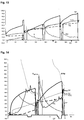
- Figures 11 to 14 are different embodiments of the cooking of elements in which the values shown in the graphs are measurements of temperatures or derivatives of temperatures with respect to time in seconds.
- Figure 11 shows the cooking process for cooking a 2 cm thick piece of veal steak in which a first turn-over thereof is carried out at about second 160.
- the temperature TC increases considerably, a fact which is not shown by the reality of the evolution of the cooking of the food 5.
- the temperature TC would have to be taken into account, but also the temperature gradient between the detected temperature in a zone close to the cooking surface TP and the temperature at the center TC.
- the derivative PC of the temperature TC decreases, since it obtained most of the heat reaching the center of the food 5 from the fluids coming from the upper part, and the heat which it receives from the lower part has still not reached the center of the food 5.
- both the temperature gradient between the center and the griddle, which is negative, and the derivatives PC of the temperature at the center TC must be taken into account. The actual equilibrium temperature if the cooking ended at that time can be known by applying these corrections.
- Figure 12 shows the cooking process for cooking a 2 cm thick ox steak, in which the phenomena mentioned in Figure 11 are observed upon carrying out a first turn-over of the food.
- Figure 12 the situation of Figure 11 is again repeated, with the same case, since it a steak cooked with 2 turns.
- the difference between Figure 11 and Figure 12 is that in Figure 11 the cooking time of the second turn-over is longer than that of the first turn-over and in Figure 12 , on the contrary, the cooking time of the first turn-over is longer than of the second turn-over.
- Figure 12 also shows a function illustrating the evolution of the pre-defined or standard heat absorption P optimal .
- the system detects that the heating power must be raised or lowered.
- the system sends a signal so that the heating power is reduced, since the temperature increment which is occurring exceeds what is necessary.
- the system when the average function PPM is less than the pre-defined heat absorption coefficient function P optimal , the system at first sends a probe repositioning signal, since foods deform during the cooking process and it is necessary to reposition the probe in the geometric center of the food. If after the repositioning the average function PPM is still less than the pre-defined heat absorption coefficient function P optimal , the system sends a signal so that the heating power is increased, since the temperature increment that is occurring is less than what is necessary.
- the system detects that the average function PPM is less than the pre-defined heat absorption coefficient P optimal , due to a deformation of the food, the probe is repositioned at about second 181, depicted by heat source control line CF. Said heat source control line CF gives the instructions to adjust the cooking to the pre-established model and the average function PPM has been compared with the P optimal , therefore it is an indication of the deviation between both.
- Figure 13 shows the cooking process for cooking a piece of steak of about 4 cm cooked with four turns. In said figure it is observed that although these jumps occur in all the turn-overs, they are greater the greater the temperature gradients between the griddle temperature and the temperature of the center.
- Figure 14 shows the cooking process for cooking a piece of tuna which, like Figure 12 , also depicts a function illustrating the evolution of the pre-defined or standard heat absorption P optimal .
- Said Figure 14 shows in the x-axis line two reductions of heating power depicted by the heating power or heat source control line CF.
Landscapes
- Physics & Mathematics (AREA)
- General Physics & Mathematics (AREA)
- Engineering & Computer Science (AREA)
- Food Science & Technology (AREA)
- Baking, Grill, Roasting (AREA)
- Electric Ovens (AREA)
- Commercial Cooking Devices (AREA)
- Electric Stoves And Ranges (AREA)
Claims (14)
- Steuerungsverfahren für einen Kochvorgang eines Lebensmittels, wobei das Lebensmittel auf einer Kochfläche gestützt ist, umfassend die folgenden Schritte:das Einführen mindestens einer Temperaturerfassungsvorrichtung in das genannte Lebensmittel in einer Erfassungszone,das Erfassen mittels der genannten mindestens einen Temperaturerfassungsvorrichtung von mehreren Temperaturwerten während mehrerer Male des Kochvorgangs innerhalb des Lebensmittels;das Erfassen mindestens eines Temperaturwertes außerhalb des genannten Lebensmittels während der genannten mehreren Male, unddas Verwenden der erfassten Temperaturwerte innerhalb des Lebensmittels und außerhalb des genannten Lebensmittels zur Steuerung des Kochvorgangs, wobei- das genannte Einführen mindestens einer Temperaturerfassungsvorrichtung (2a, 2b, 2c) mit Hilfe von Positionierungsmitteln (3a, 3b, 3c) durchgeführt wird, so dass die genannte mindestens eine Temperaturerfassungsvorrichtung innerhalb des genannten Lebensmittels (5) in einer Erfassungszone bis zu einer vorbestimmten Einführtiefe in Bezug auf die Dicke des Lebensmittels positioniert wird, so dass eine erfasste Temperatur TC jederzeit während des Kochens in der genannten Erfassungszone erhalten werden kann;dadurch gekennzeichnet, dass das Verfahren zusätzlich Folgendes umfasst:- das Verarbeiten während des Kochens der Daten der genannten Temperatur TC in der genannten Erfassungszone und der Daten einer Temperatur TP der Kochfläche durch welche das Lebensmittel Kochheizenergie absorbiert und das Bestimmen, jedes der genannten mehreren Male des Kochvorgangs, eines Temperaturgradienten zwischen der Zone, durch welche das Lebensmittel die Kochheizenergie empfängt, und der genannten Erfassungszone innerhalb des Lebensmittels;- das Beurteilen der Veränderung der genannten Temperatur TC mindestens zur ersten Ableitung; und- das Verwenden der genannten Beurteilung der Veränderung der Temperatur TC und des genannten Gradienten zur Steuerung des Kochvorgangs.
- Verfahren nach Anspruch 1, wobei das Lebensmittel (5) die Heizenergie durch eine Oberfläche, auf welche es gestützt ist, durch die Anwendung einer Kochheizenergiequelle unter dem genannten Lebensmittel (5) empfängt, wobei der genannte Kochvorgang mindestens eine Wendung oder einen Kochschritt beinhaltet, welcher Folgendes umfasst:- das Bestimmen des mindestens einen Zeitpunkts der genannten Wendung, welcher vom Benutzer gemäß:- der genannten Temperatur TC der Erfassungsvorrichtung zum Zeitpunkt vor jeder Wendung;- der Entwicklung der Temperatur der genannten Erfassungszone, bestimmt durch die genannte Verarbeitung beinhaltend mindestens eine erste Ableitung der Temperatur TC; und- des genannten Temperaturgradienten zwischen dem Äußeren des Lebensmittels in Kontakt mit der Kochfläche und der genannten Erfassungszone, innerhalb des Lebensmittels,vordefiniert werden kann, und- das Positionieren der genannten Erfassungsvorrichtung nach jeder Wendung des Lebensmittels, basierend auf der Dicke des Lebensmittels, bis zu einer vorbestimmten Einführtiefe und/oder in einem Abstand zu einer Oberfläche, durch welche das Lebensmittel Kochheizenergie absorbiert, mit Hilfe von den genannten Positionierungsmitteln.
- Verfahren nach Anspruch 2, wobei die genannte Erfassungszone eine Mittelzone in Bezug auf die Dicke des Lebensmittels ist und die Temperatur am Ende mindestens eines Kochschritts in der genannten Mittelzone, oder berechnete Mittentemperatur TCC, mittels des folgenden Ausdrucks bestimmt wird
 TC = zu jeder Zeit gemessene Mittentemperatur,TP = Temperatur der Kochfläche,F = Korrekturfaktor abhängig von den physikalischen Merkmalen des Lebensmittels, vom Lebensmitteltyp und vom Zusammenhang zwischen den Zeitableitungen der TC und der TP, welcher den Absorptionswert der an jedem der Zeitpunkte empfangene Heizenergie ausdrückt und welcher mindestens die Dicke des genannten Lebensmittels, den Wassergehalt desselben und die Richtung dessen Fasern umfasst,D1 = Korrekturfaktor abhängig vom Wert der ersten Ableitung von TC,D2 = Korrekturfaktor abhängig vom Wert der Veränderung der ersten Ableitung von TC oder der zweiten Ableitung.
 - Verfahren nach Anspruch 3, umfassend:- das Einführen in das Lebensmittel (5) mindestens zweier der genannten Temperaturerfassungsvorrichtungen (2a, 2b, 2c), mit Hilfe von den genannten Positionierungsmitteln, indem sie jeweils innerhalb des Lebensmittels bis zu einer vorbestimmten Einführtiefe in Bezug auf die Dicke des Lebensmittels platziert werden; unddas Steuern der Temperatur und Entwicklung der Temperatur jeder der genannten Erfassungsvorrichtungen (2a, 2b, 2c) unter Analyse mit einer gewissen Frequenz der Daten oder Ablesungen aus den genannten Temperaturerfassungsvorrichtungen (2a, 2b, 2c) um die erfasste Mittentemperatur TC und die berechnete Mittentemperatur TCC des Lebensmittels (5) im Laufe der Zeit zu kennen.
- Verfahren nach Anspruch 2, umfassend das Vergleichen der Werte der genannten erfassten Mittentemperatur TC mit dem Wert einer Zielmittentemperatur TCO, welcher vom Benutzer abhängig vom für das Lebensmittel (5) benötigte Kochpunkt vordefiniert wird, so dass die genannte Wärmequelle gemäß dem Ergebnis der genannten Vergleiche gesteuert wird.
- Verfahren nach Anspruch 2, umfassend:das Messen der abgelaufenen Zeit t1 zwischen der genannten Anwendung der genannten Wärmequelle unter dem Lebensmittel (5) und der Zeit, bei welcher ein Signal S1, welches angibt, dass es nötig ist das genannte Lebensmittel zu wenden, erzeugt worden ist, und sobald das genannte Lebensmittel (5) gewendet worden ist, das Aufrechterhalten der Anwendung der genannten Wärmequelle unter dem Lebensmittel (5) während einer Anwendungszeit t2 gemäß der genannten gemessenen Zeit t1; unddas Steuern der genannten Wärmequelle, um eine gleiche oder unterschiedliche Heizleistung während der gemessenen Zeit t1 vor der Wendung des Lebensmittels (5) und während der Anwendungszeit t2, sobald das Lebensmittel (5) gewendet worden ist, anzuwenden,wobei die genannte Steuerung der Wärmequelle mittels einer Reihe von vordefinierten aufeinanderfolgenden Zunahmen oder Abnahmen der Heizleistung durchgeführt wird, unter Berücksichtigung einer anfänglichen Mittentemperatur TCI des Lebensmittels und der Entwicklung der TP.
- Verfahren nach Anspruch 3, umfassend das Analysieren der Veränderung der genannten Werten der erfassten Mittentemperatur TC und der erfassten Temperatur der Kochfläche TP im Laufe der Zeit, mittels einer Reihe von Ablesungen, sowie das Berechnen einer Wärmeabsorptionsfunktion des Lebensmittels bezüglich der Zeit, welche eine Neigungsfunktion TP oder TC ist, erhalten aus dem Ergebnis der Entwicklung der Temperaturwerte, welche kohärent im Laufe der Zeit sind, um festzustellen:- dass die genannte Entwicklung kohärent oder nicht kohärent ist, gemäß dem Unterschied der Werte zwischen jeder zwei der genannten Ablesungen, und- dass die Mittentemperatur TC und die erfasste Temperatur der Kochfläche TP gemäß dem Zeichen des Unterschiedes zwischen aufeinanderfolgenden Werten zunimmt oder abnimmt, und dass:- wenn festgestellt wird, dass die Entwicklung der Werte der erfassten Mittentemperatur TC nicht kohärent ist, das Verfahren Folgendes umfasst: das Berücksichtigen der Ergebnisse der genannten Vergleiche der erfassten Mittentemperatur TC mit der genannten Zielmittentemperatur TCO als ungültig, bis es festgestellt werden, dass die Entwicklung kohärent ist; und- wenn festgestellt wird, dass die Entwicklung der Werte der erfassten Mittentemperatur TC kohärent und dass die Entwicklung der genannten Neigungsfunktion PC negativ ist, aber das Ergebnis der genannten Funktion der berechneten Mittentemperatur TCC größer als der Wert der berechneten Zielmittentemperatur TCCO für eine aufeinanderfolgende Anzahl von Ablesungen ist, wobei das Verfahren die Anzeige, dass das Lebensmittel (5) gekocht wird, umfasst;- wenn festgestellt wird, dass die Entwicklung der Werte der erfassten Mittentemperatur TC, nach der Erfassung mindestens einer Wendung des Lebensmittels (5), nicht kohärent ist oder ob kohärent oder nicht kohärent ist, nehmen die Werte in mehreren aufeinanderfolgenden Ablesungen zu, und größer als der Wert der Zielmittentemperatur TCO sind, wobei das Verfahren das Anzeigen, dass das Lebensmittel (5) gekocht wird, umfasst; und- wenn die erfasste Mittentemperatur TC den Wert der Zielmittentemperatur TCO erreicht und die Entwicklung der genannten Neigungsfunktion PC positiv oder gleich null für eine aufeinanderfolgende Anzahl von vorherigen Ablesungen und eine aufeinanderfolgende Anzahl von Ablesungen nach der Zeit bei welcher beide Temperaturen TC, TCO übereinstimmen oder TC>TCO ist, umfasst das Verfahren das Anzeigen dass das Lebensmittel (5) gekühlt wird.
- Verfahren nach Anspruch 3 oder 7, zusätzlich umfassend:- das Berechnen einer Funktion der berechneten Zielmittentemperatur TCCO des Lebensmittels (5), erhalten durch das Hinzufügen zur Zielmittentemperatur TCO eines Sicherheitsfaktors aufgrund des Wärmeverlustes, welcher im Lebensmittel (5) erlebt wird, wenn der Kochvorgang zu Ende geht:das Platzieren des genannten Lebensmittels (5) auf einer Oberfläche bei einer Temperatur kleiner als die genannte Temperatur TCO, unter Vergleichung der Werte der genannten berechneten Mittentemperatur TCC mit dem Wert der genannten berechneten Zielmittentemperatur TCCO; unddas Steuern der genannten Wärmequelle gemäß dem Ergebnis der genannten Vergleiche.
- Verfahren nach den Ansprüchen 2 oder 3, umfassend das Berechnen mindestens einer Wärmeabsorptionskoeffizientenfunktion des Lebensmittels bezüglich der Zeit, welche die Werte der erfassten Temperatur nah an der Kochfläche TP mit einer optimalen Wärmeabsorptionskoeffizientenfunktion Poptimal und einer gewissen konstanten Heizleistung in Verbindung bringt, so dass eine Feinanpassung der von der Wärmequelle zuzuführenden Heizleistung erlaubt wird, wobei die genannte Funktion oder Funktionen zwei Merkmale aufweisen:- sie sind Exponentialgleichungen; und- für einen Temperaturwert TP von 100ºC, ist der Wert des optimalen Wärmeabsorptionskoeffizienten Poptimal gleich oder nah an Nullund dass:- die genannte berechnete Wärmeabsorptionskoeffizientenfunktion des Lebensmittels bezüglich der Zeit mindestens eine Neigungsfunktion PP ist, welche als Ergebnis der Entwicklung der kohärenten Werte der erfassten Temperatur nah an der Kochfläche TP im Laufe der Zeit erhalten wird; oder- die genannte berechnete Wärmeabsorptionskoeffizientenfunktion des Lebensmittels bezüglich der Zeit eine Durchschnittsfunktion PPM einer Neigungsfunktion PP ist, welche als Ergebnis der Entwicklung der Werte der erfassten Temperatur der Kochfläche TP im Laufe der Zeit erhalten wird,so dass, wenn die Heizleistung bekannt ist, die genannte Wärmeabsorptionsfunktion die Berechnung der Zeit ermöglicht, welche die TP das Lebensmittel zwischen einer anfänglichen TP und einer anderen endgültigen TP halten wird.
- Kochvorrichtung zur Steuerung des Kochvorgangs des Lebensmittels gemäß dem Verfahren nach einem der Ansprüche 1-9, wobei das Lebensmittel auf einer Kochfläche gestützt ist, beinhaltend eine Erfassungsvorrichtung (2a, 2b, 2c), umfassend eine Temperaturerfassungsvorrichtung, welche dazu angepasst ist, innerhalb des Lebensmittels (5) eingeführt zu werden,
dadurch gekennzeichnet, dass sie zusätzlich Folgendes umfasst:- Mittel zur Bestimmung der Dicke des Lebensmittels (5) jederzeit während des Kochvorgangs, beinhaltend eine mechanische Vorrichtung oder ein elektronisches Messgerät, mit mindestens einer Erfassungsvorrichtung, welche dafür geeignet ist, die genannte Dicke mit oder ohne Kontakt mit dem Lebensmittel (5) zu erfassen, wobei die genannte elektronische Erfassungsvorrichtung mindestens einen Emitter und einen Empfänger von Mikrowellen oder Ultraschall einschließt, und- Positionierungsmittel, umfassend mindestens eine Kanüle, welche in das Lebensmittel eingeführt werden kann, um die genannte Erfassungsvorrichtung innerhalb des genannten Lebensmittels (5) bis zu einer vorbestimmten Einführtiefe in Bezug auf die Dicke des Lebensmittels zu positionieren. - Vorrichtung nach Anspruch 10, wobei:- die genannten Mittel zur Bestimmung der Dicke des Lebensmittels einen Anschlag umfassen, welcher entlang der genannten mindestens einen Kanüle der genannten Positionierungsmittel beweglich ist, welche Kanüle ein Ende aufweist, welches dazu bestimmt ist, auf der Referenzoberfläche (6) gestützt zu werden, nachdem es das Lebensmittel (5) quer überquert hat;die genannten Positionierungsmittel dazu angepasst sind, mindestens die genannte Erfassungsvorrichtung (2a, 2b, 2c) in einem absoluten vorbestimmten Abstand in Bezug auf eine Referenzoberfläche (6), auf welcher das Lebensmittel (5) gestützt ist, oder in Bezug auf den genannten beweglichen Anschlag zu positionieren; und
die genannten Positionierungsmittel mindestens teilweise automatisch arbeiten, umfassend einen Übertragungsmechanismus, welcher mit den Kanülen (3a, 3b, 3c) oder mit dem genannten Anschlag (4) und den Kanülen (3a, 3b, 3c) assoziiert ist, wobei der genannte Übertragungsmechanismus mindestens einen Lager oder mindestens ein Getriebe oder eine Vielzahl von Umlenkrollen oder einen Hebel, welche an einer Basis angelenkt ist, und eine Vielzahl von parallelen Stangen, welche mit dem genannten Hebel assoziiert sind, umfasst. - Vorrichtung nach Anspruch 10 oder 11, wobei
die genannte Erfassungsvorrichtung (2a) in der Kanüle (3a) fixiert oder integriert ist und in einem absoluten vorbestimmten Abstand vom Ende der genannten Kanüle (3a) getrennt ist; und
wobei die genannte Vorrichtung nach Anspruch 10 oder 11 zwei oder mehr der genannten Erfassungsvorrichtungen (2a, 2b, 2c) einschließt, so dass jede derselben in einer Einführtiefe bezüglich der Dicke des Lebensmittels angeordnet werden kann, wobei jede der genannten Erfassungsvorrichtungen (2a, 2b, 2c) dazu angepasst ist, als Antwort auf Änderungen bei der Dicke und/oder Form des Lebensmittels während des Kochvorgangs neu positioniert zu werden, so dass die relative Positionen in Bezug auf die neue Dicke und/oder neue Form des Lebensmittels (5) aufrechterhalten werden. - Vorrichtung nach Anspruch 10, wobei- die genannten Positionierungsmittel eine Verankerung umfassen, zur Fixierung an der Oberfläche des Lebensmittels (5) für den Zweck die relative Positionen der Erfassungsvorrichtungen (2a, 2b, 2c) als Antwort auf Änderungen bei der Form des Lebensmittels (5) aufrechtzuerhalten;- die erwähnte Verankerung am Ende der Kanüle (3a), welche das Lebensmittel (5) überquert, angeordnet ist und dass die Verankerung einen Sensor umfassen kann, welcher dafür geeignet ist, den Kontakt der Verankerung mit der Stützoberfläche (6) zu erfassen; und- die genannten Positionierungsmittel zusätzlich eine Schubvorrichtung einschließen können, welche dazu angeordnet ist, in der Betriebsposition, den genannten Anschlag (4) zum Lebensmittel (5) hin zu schieben, so dass im Falle dass sich die Dicke des Lebensmittels (5) verringert, der Anschlag (4) dessen Position ändert, bis er in Kontakt mit der Oberfläche des Lebensmittels (5) kommt, welche der Referenzoberfläche (6) entgegengesetzt ist, für den Zweck die neue Dicke des Lebensmittels (5) zu bestimmen, um die Erfassungsvorrichtungen (2a, 2b, 2c) neu zu positionieren, die Änderungen bei der Dicke und/oder Form des Lebensmittels (5) während es gekocht wird zu bewältigen, unter Aufrechterhaltung der relativen Positionen in Bezug auf die neue Dicke und/oder neue Form desselben.
- Vorrichtung nach einem der Ansprüche 10 bis 13, welche dazu angepasst ist, sich mit einem elektronischen System mit Verarbeitungsmitteln zu kommunizieren, in Verbindung mit mindestens den genannten Erfassungsvorrichtungen (2a, 2b, 2c) und/oder Erfassungsvorrichtungen, zur Erfassung der Raumtemperatur in der Kochanlage und/oder der Temperatur der Oberfläche des Lebensmittels (5) und/oder die genannten Mittel dazu angepasst sind, die Dicke des Lebensmittels (5) zu bestimmen, mindestens aus den genannten Vorrichtungen oder Mitteln empfangenen Daten zu verarbeiten und/oder Einträge der genannten Daten zu speichern und dass das genannte elektronische System Anzeigeelemente umfasst, und dazu angepasst ist, die genannten Anzeigeelemente zu aktivieren, wenn die erfassten Temperaturen gewisse Werte erreichen und/oder wenn die genannten Werte eine gewisse Zeit lang aufrechterhalten werden,
wobei das elektronische System Steuermittel einschließt, welche mit den genannten Verarbeitungsmittel assoziiert sind, um eine Kochvorrichtung zum Kochen des Lebensmittels (5) gemäß den verarbeiteten Daten zu steuern, mindestens in Bezug auf die Temperatur, und auf vorbestimmte und/oder programmierbare Kochparameter.
Applications Claiming Priority (2)
| Application Number | Priority Date | Filing Date | Title |
|---|---|---|---|
| ES200700243A ES2328769B1 (es) | 2007-01-24 | 2007-01-24 | Dispositivo y metodo para el control de la coccion de alimentos. |
| PCT/ES2008/000037 WO2008090250A1 (es) | 2007-01-24 | 2008-01-24 | Método y dispositivo para el control de la cocción de alimentos |
Publications (3)
| Publication Number | Publication Date |
|---|---|
| EP2108929A1 EP2108929A1 (de) | 2009-10-14 |
| EP2108929A4 EP2108929A4 (de) | 2012-12-26 |
| EP2108929B1 true EP2108929B1 (de) | 2018-07-04 |
Family
ID=39644156
Family Applications (1)
| Application Number | Title | Priority Date | Filing Date |
|---|---|---|---|
| EP08718438.8A Not-in-force EP2108929B1 (de) | 2007-01-24 | 2008-01-24 | Steuerungsverfahren und -vorrichtung zum kochen von lebensmitteln |
Country Status (4)
| Country | Link |
|---|---|
| US (1) | US8609168B2 (de) |
| EP (1) | EP2108929B1 (de) |
| ES (2) | ES2328769B1 (de) |
| WO (1) | WO2008090250A1 (de) |
Families Citing this family (33)
| Publication number | Priority date | Publication date | Assignee | Title |
|---|---|---|---|---|
| ITMO20040211A1 (it) * | 2004-08-06 | 2004-11-06 | G I S P A Sa | Sistema di controllo della riduzione della temoperatura di un alimento. |
| WO2013059632A1 (en) * | 2011-10-19 | 2013-04-25 | John Rankin | Method for indirect food temperature measurement |
| FR2985649B1 (fr) * | 2012-01-16 | 2016-03-11 | Seb Sa | Procede de cuisson d'aliments et appareil mettant en oeuvre ce procede |
| FR2985650B1 (fr) * | 2012-01-16 | 2016-03-11 | Seb Sa | Procede d'information d'une cuisson d'aliment et appareil associe |
| US10219531B2 (en) * | 2012-04-16 | 2019-03-05 | Iceberg Luxembourg S.A.R.L. | Preservation system for nutritional substances |
| US9063019B2 (en) | 2012-11-28 | 2015-06-23 | Erie Instruments, Llc | Device for positioning a temperature sensor |
| DE102012222151A1 (de) * | 2012-12-04 | 2014-06-05 | BSH Bosch und Siemens Hausgeräte GmbH | Verfahren und Vorrichtung zum Bestimmen einer effektiven Kerntemperatur eines Garguts |
| US9392899B2 (en) * | 2013-08-02 | 2016-07-19 | Conair Corporation | Temperature sensing and control system for a cooking appliance |
| US20150118368A1 (en) * | 2013-10-24 | 2015-04-30 | Ching-Chuan Lin | Method for executing heating according property of food |
| WO2016177628A1 (en) * | 2015-05-04 | 2016-11-10 | Nestec S.A. | System and method for food processing |
| FR3039052B1 (fr) * | 2015-07-21 | 2017-07-21 | Seb Sa | Procede de commande du temps de cuisson et appareil de cuisson associe |
| EP3184978B1 (de) * | 2015-12-22 | 2020-02-12 | Electrolux Appliances Aktiebolag | Nahrungsmittelsonde zur ermittlung der temperatur im innern von nahrungsmitteln |
| GB201600445D0 (en) * | 2016-01-11 | 2016-02-24 | Cairns Intellectual Property Ltd | Methods and apparatuses for temperature measurement |
| WO2017121691A1 (en) | 2016-01-14 | 2017-07-20 | Koninklijke Philips N.V. | Kitchen appliance and cooking monitoring method |
| US20180143086A1 (en) * | 2016-11-22 | 2018-05-24 | Electrolux Home Products, Inc. | Cooking temperature sensor with submersed probe |
| AU2018230391B2 (en) * | 2017-03-08 | 2020-11-19 | Louis S. Polster | Methods and systems for heat treating a food product |
| US10620055B2 (en) * | 2017-08-14 | 2020-04-14 | Maverick Industries, Inc. | Cooking thermometers and multi-function cooking tools having count-up timers |
| CN107361653B (zh) * | 2017-08-16 | 2021-12-03 | 广东美的厨房电器制造有限公司 | 烤盘组件以及烤箱 |
| US10080524B1 (en) * | 2017-12-08 | 2018-09-25 | VivaLnk, Inc. | Wearable thermometer patch comprising a temperature sensor array |
| US20190327795A1 (en) * | 2018-04-24 | 2019-10-24 | Haier Us Appliance Solutions, Inc. | Oven appliance with direct temperature measurement and related methods |
| US11109765B2 (en) | 2018-08-20 | 2021-09-07 | VivaLnk, Inc. | Wearable thermometer patch comprising a temperature sensor array |
| CN109558640B (zh) * | 2018-10-31 | 2023-06-20 | 深圳和而泰智能控制股份有限公司 | 温度确定方法、装置、计算机设备和存储介质 |
| EP3690411A1 (de) | 2019-01-30 | 2020-08-05 | Electrolux Appliances Aktiebolag | Messvorrichtung |
| CN110360974B (zh) * | 2019-06-27 | 2021-08-10 | 广东美的厨房电器制造有限公司 | 食物厚度估测方法及相关装置 |
| ES3005845T3 (en) * | 2020-01-21 | 2025-03-17 | Vorwerk Co Interholding | Supply unit for generating electrical energy, kitchen utensil and kitchen system |
| US12070146B2 (en) | 2020-12-31 | 2024-08-27 | Sharkninja Operating Llc | Cooking device and components thereof |
| WO2022192288A1 (en) | 2021-03-09 | 2022-09-15 | Tyson Foods, Inc. | Method and apparatus for non-contact temperature measurement of a food item |
| ES2976314T3 (es) * | 2021-07-13 | 2024-07-29 | Vorwerk Co Interholding | Termómetro para alimentos y procedimiento para una preparación de alimentos |
| CN114994248B (zh) * | 2022-05-25 | 2023-04-07 | 玉田县自豪食品有限公司 | 一种真空腌制装置及方法 |
| US12405173B2 (en) * | 2022-08-05 | 2025-09-02 | Maverick Industries, Inc. | Digital cooking thermometers having dynamo assemblies incorporated therein for generating electrical power utilized for operating the thermometers |
| CN116421063A (zh) * | 2023-04-26 | 2023-07-14 | 宁波方太厨具有限公司 | 一种烹饪工作方法 |
| WO2025219617A1 (es) * | 2024-04-15 | 2025-10-23 | Earcrob, S.L.U. | Dispositivo y método de control de cocción de alimentos |
| CN119666172A (zh) * | 2024-12-30 | 2025-03-21 | 深圳市梵盛达技术有限公司 | 温度测量设备 |
Family Cites Families (9)
| Publication number | Priority date | Publication date | Assignee | Title |
|---|---|---|---|---|
| US4441693A (en) | 1982-06-01 | 1984-04-10 | Sidney Silver | Jack accessory support leg for trailer hitch |
| DE4032949C2 (de) * | 1990-10-17 | 1998-04-30 | Miele & Cie | Backofen |
| DE19609116A1 (de) | 1996-03-08 | 1997-09-18 | Eloma Gmbh | Verfahren und Vorrichtung zum Garen von Nahrungsmitteln |
| US5983783C1 (en) * | 1999-04-22 | 2001-01-30 | Brookstone Co Inc | Electronic chef's fork |
| DE19945021C2 (de) * | 1999-09-20 | 2003-10-23 | Rational Ag | Verfahren zum Steuern eines Garprozesses und hierzu verwendbare Garprozeßfühlereinrichtung |
| FR2854459B1 (fr) | 2003-04-29 | 2005-07-22 | Brandt Ind | Ustensile de cuisine et procede et dispositif d'asservissement de moyens de chauffage d'un appareil de cuisson |
| DE10332021B3 (de) * | 2003-07-15 | 2005-04-14 | Diehl Ako Stiftung & Co. Kg | Verfahren zum Bestimmen von Parametern eines Garprozesses eines Nahrungsmittels und dieses benutzende Steuervorrichtung |
| DE502005000527D1 (de) * | 2005-02-02 | 2007-05-10 | Frima Sa | Verfahren und Vorrichtung zum Bestimmen eines Wendezeitpunktes eines Gargutes |
| ES2268983B1 (es) * | 2005-07-21 | 2008-03-01 | Earcrob, S.L. | Dispositivo y procedimiento para el control de la coccion de alimentos. |
-
2007
- 2007-01-24 ES ES200700243A patent/ES2328769B1/es active Active
-
2008
- 2008-01-24 US US12/524,409 patent/US8609168B2/en not_active Expired - Fee Related
- 2008-01-24 WO PCT/ES2008/000037 patent/WO2008090250A1/es not_active Ceased
- 2008-01-24 EP EP08718438.8A patent/EP2108929B1/de not_active Not-in-force
- 2008-01-24 ES ES08718438.8T patent/ES2689666T3/es active Active
Non-Patent Citations (1)
| Title |
|---|
| None * |
Also Published As
| Publication number | Publication date |
|---|---|
| EP2108929A4 (de) | 2012-12-26 |
| ES2328769B1 (es) | 2010-08-30 |
| WO2008090250A1 (es) | 2008-07-31 |
| US8609168B2 (en) | 2013-12-17 |
| ES2689666T3 (es) | 2018-11-15 |
| ES2328769A1 (es) | 2009-11-17 |
| EP2108929A1 (de) | 2009-10-14 |
| US20090324785A1 (en) | 2009-12-31 |
Similar Documents
| Publication | Publication Date | Title |
|---|---|---|
| EP2108929B1 (de) | Steuerungsverfahren und -vorrichtung zum kochen von lebensmitteln | |
| EP3172996B1 (de) | Kochsystem | |
| CN104080381B (zh) | 烹饪食物的方法,和实施所述方法的装置 | |
| EP3682206B1 (de) | Intelligentes fleischthermometer | |
| US5827556A (en) | Electronic controller for heating apparatus | |
| EP3125644B1 (de) | Verfahren und computerprogramm zur steuerung eines frittiergeräts und frittiergerät zur durchführung des verfahrens | |
| EP1918643A2 (de) | Kochvorrichtung und Verfahren zur Anzeige von Informationen über Kalorien | |
| US20080043809A1 (en) | Thermometer | |
| CN106659330A (zh) | 烹饪装置 | |
| EP1624267B1 (de) | Temperaturkontrollsystem für Nahrungsmittel | |
| EP2939497B1 (de) | Vorrichtung und verfahren zur bestimmung der kerntemperatur von nahrungsmitteln | |
| CN104066366A (zh) | 提供食物烹饪信息的方法,和相关的装置 | |
| AU2017347919B2 (en) | Electronic temperature control system for a grill | |
| EA012915B1 (ru) | Устройство и способ приготовления пищи с распознаванием продукта | |
| WO2019052613A1 (en) | INTELLIGENT MEAT THERMOMETER | |
| KR101048897B1 (ko) | 그릴 제어 시스템 및 방법 | |
| WO2007009880A1 (en) | Device and method for controlling the cooking of foods | |
| US6814487B2 (en) | Apparatus for measuring internal temperatures of food patties | |
| CN104919891A (zh) | 用于确定食物的芯部温度的装置和方法 | |
| ES2945488A1 (es) | Metodo para monitorizar el estado de coccion de un alimento para un aparato para cocinar alimentos a la plancha | |
| TR201807447T4 (tr) | Su hazneli bir pişirici cihaz. | |
| DE102020209296A1 (de) | Verfahren und Einrichtung zum Kalibrieren eines Temperatursensors | |
| JPH0742944A (ja) | マイクロ波オーブンに入れた食物の重量決定方法及び装置 | |
| JP2010277791A (ja) | 誘導加熱調理器 | |
| MXPA98005044A (en) | Electronic controller for heating apparatus |
Legal Events
| Date | Code | Title | Description |
|---|---|---|---|
| PUAI | Public reference made under article 153(3) epc to a published international application that has entered the european phase |
Free format text: ORIGINAL CODE: 0009012 |
|
| 17P | Request for examination filed |
Effective date: 20081231 |
|
| AK | Designated contracting states |
Kind code of ref document: A1 Designated state(s): AT BE BG CH CY CZ DE DK EE ES FI FR GB GR HR HU IE IS IT LI LT LU LV MC MT NL NO PL PT RO SE SI SK TR |
|
| DAX | Request for extension of the european patent (deleted) | ||
| A4 | Supplementary search report drawn up and despatched |
Effective date: 20121122 |
|
| RIC1 | Information provided on ipc code assigned before grant |
Ipc: G01K 1/14 20060101AFI20121116BHEP Ipc: A47J 27/62 20060101ALI20121116BHEP |
|
| 17Q | First examination report despatched |
Effective date: 20160628 |
|
| STAA | Information on the status of an ep patent application or granted ep patent |
Free format text: STATUS: EXAMINATION IS IN PROGRESS |
|
| GRAP | Despatch of communication of intention to grant a patent |
Free format text: ORIGINAL CODE: EPIDOSNIGR1 |
|
| STAA | Information on the status of an ep patent application or granted ep patent |
Free format text: STATUS: GRANT OF PATENT IS INTENDED |
|
| INTG | Intention to grant announced |
Effective date: 20180208 |
|
| GRAS | Grant fee paid |
Free format text: ORIGINAL CODE: EPIDOSNIGR3 |
|
| GRAA | (expected) grant |
Free format text: ORIGINAL CODE: 0009210 |
|
| STAA | Information on the status of an ep patent application or granted ep patent |
Free format text: STATUS: THE PATENT HAS BEEN GRANTED |
|
| RAP1 | Party data changed (applicant data changed or rights of an application transferred) |
Owner name: EARCROB, S.L.U. |
|
| AK | Designated contracting states |
Kind code of ref document: B1 Designated state(s): AT BE BG CH CY CZ DE DK EE ES FI FR GB GR HR HU IE IS IT LI LT LU LV MC MT NL NO PL PT RO SE SI SK TR |
|
| REG | Reference to a national code |
Ref country code: GB Ref legal event code: FG4D |
|
| REG | Reference to a national code |
Ref country code: CH Ref legal event code: EP |
|
| REG | Reference to a national code |
Ref country code: AT Ref legal event code: REF Ref document number: 1015011 Country of ref document: AT Kind code of ref document: T Effective date: 20180715 |
|
| REG | Reference to a national code |
Ref country code: IE Ref legal event code: FG4D |
|
| REG | Reference to a national code |
Ref country code: DE Ref legal event code: R096 Ref document number: 602008055829 Country of ref document: DE |
|
| REG | Reference to a national code |
Ref country code: NL Ref legal event code: MP Effective date: 20180704 |
|
| REG | Reference to a national code |
Ref country code: ES Ref legal event code: FG2A Ref document number: 2689666 Country of ref document: ES Kind code of ref document: T3 Effective date: 20181115 |
|
| REG | Reference to a national code |
Ref country code: LT Ref legal event code: MG4D |
|
| REG | Reference to a national code |
Ref country code: AT Ref legal event code: MK05 Ref document number: 1015011 Country of ref document: AT Kind code of ref document: T Effective date: 20180704 |
|
| PG25 | Lapsed in a contracting state [announced via postgrant information from national office to epo] |
Ref country code: NL Free format text: LAPSE BECAUSE OF FAILURE TO SUBMIT A TRANSLATION OF THE DESCRIPTION OR TO PAY THE FEE WITHIN THE PRESCRIBED TIME-LIMIT Effective date: 20180704 |
|
| PG25 | Lapsed in a contracting state [announced via postgrant information from national office to epo] |
Ref country code: GR Free format text: LAPSE BECAUSE OF FAILURE TO SUBMIT A TRANSLATION OF THE DESCRIPTION OR TO PAY THE FEE WITHIN THE PRESCRIBED TIME-LIMIT Effective date: 20181005 Ref country code: FI Free format text: LAPSE BECAUSE OF FAILURE TO SUBMIT A TRANSLATION OF THE DESCRIPTION OR TO PAY THE FEE WITHIN THE PRESCRIBED TIME-LIMIT Effective date: 20180704 Ref country code: NO Free format text: LAPSE BECAUSE OF FAILURE TO SUBMIT A TRANSLATION OF THE DESCRIPTION OR TO PAY THE FEE WITHIN THE PRESCRIBED TIME-LIMIT Effective date: 20181004 Ref country code: AT Free format text: LAPSE BECAUSE OF FAILURE TO SUBMIT A TRANSLATION OF THE DESCRIPTION OR TO PAY THE FEE WITHIN THE PRESCRIBED TIME-LIMIT Effective date: 20180704 Ref country code: SE Free format text: LAPSE BECAUSE OF FAILURE TO SUBMIT A TRANSLATION OF THE DESCRIPTION OR TO PAY THE FEE WITHIN THE PRESCRIBED TIME-LIMIT Effective date: 20180704 Ref country code: IS Free format text: LAPSE BECAUSE OF FAILURE TO SUBMIT A TRANSLATION OF THE DESCRIPTION OR TO PAY THE FEE WITHIN THE PRESCRIBED TIME-LIMIT Effective date: 20181104 Ref country code: PL Free format text: LAPSE BECAUSE OF FAILURE TO SUBMIT A TRANSLATION OF THE DESCRIPTION OR TO PAY THE FEE WITHIN THE PRESCRIBED TIME-LIMIT Effective date: 20180704 Ref country code: LT Free format text: LAPSE BECAUSE OF FAILURE TO SUBMIT A TRANSLATION OF THE DESCRIPTION OR TO PAY THE FEE WITHIN THE PRESCRIBED TIME-LIMIT Effective date: 20180704 Ref country code: CZ Free format text: LAPSE BECAUSE OF FAILURE TO SUBMIT A TRANSLATION OF THE DESCRIPTION OR TO PAY THE FEE WITHIN THE PRESCRIBED TIME-LIMIT Effective date: 20180704 Ref country code: BG Free format text: LAPSE BECAUSE OF FAILURE TO SUBMIT A TRANSLATION OF THE DESCRIPTION OR TO PAY THE FEE WITHIN THE PRESCRIBED TIME-LIMIT Effective date: 20181004 |
|
| PG25 | Lapsed in a contracting state [announced via postgrant information from national office to epo] |
Ref country code: LV Free format text: LAPSE BECAUSE OF FAILURE TO SUBMIT A TRANSLATION OF THE DESCRIPTION OR TO PAY THE FEE WITHIN THE PRESCRIBED TIME-LIMIT Effective date: 20180704 Ref country code: HR Free format text: LAPSE BECAUSE OF FAILURE TO SUBMIT A TRANSLATION OF THE DESCRIPTION OR TO PAY THE FEE WITHIN THE PRESCRIBED TIME-LIMIT Effective date: 20180704 |
|
| REG | Reference to a national code |
Ref country code: DE Ref legal event code: R097 Ref document number: 602008055829 Country of ref document: DE |
|
| PG25 | Lapsed in a contracting state [announced via postgrant information from national office to epo] |
Ref country code: RO Free format text: LAPSE BECAUSE OF FAILURE TO SUBMIT A TRANSLATION OF THE DESCRIPTION OR TO PAY THE FEE WITHIN THE PRESCRIBED TIME-LIMIT Effective date: 20180704 Ref country code: EE Free format text: LAPSE BECAUSE OF FAILURE TO SUBMIT A TRANSLATION OF THE DESCRIPTION OR TO PAY THE FEE WITHIN THE PRESCRIBED TIME-LIMIT Effective date: 20180704 |
|
| PLBE | No opposition filed within time limit |
Free format text: ORIGINAL CODE: 0009261 |
|
| STAA | Information on the status of an ep patent application or granted ep patent |
Free format text: STATUS: NO OPPOSITION FILED WITHIN TIME LIMIT |
|
| PG25 | Lapsed in a contracting state [announced via postgrant information from national office to epo] |
Ref country code: DK Free format text: LAPSE BECAUSE OF FAILURE TO SUBMIT A TRANSLATION OF THE DESCRIPTION OR TO PAY THE FEE WITHIN THE PRESCRIBED TIME-LIMIT Effective date: 20180704 Ref country code: SK Free format text: LAPSE BECAUSE OF FAILURE TO SUBMIT A TRANSLATION OF THE DESCRIPTION OR TO PAY THE FEE WITHIN THE PRESCRIBED TIME-LIMIT Effective date: 20180704 |
|
| 26N | No opposition filed |
Effective date: 20190405 |
|
| PG25 | Lapsed in a contracting state [announced via postgrant information from national office to epo] |
Ref country code: SI Free format text: LAPSE BECAUSE OF FAILURE TO SUBMIT A TRANSLATION OF THE DESCRIPTION OR TO PAY THE FEE WITHIN THE PRESCRIBED TIME-LIMIT Effective date: 20180704 Ref country code: MC Free format text: LAPSE BECAUSE OF FAILURE TO SUBMIT A TRANSLATION OF THE DESCRIPTION OR TO PAY THE FEE WITHIN THE PRESCRIBED TIME-LIMIT Effective date: 20180704 |
|
| PG25 | Lapsed in a contracting state [announced via postgrant information from national office to epo] |
Ref country code: LU Free format text: LAPSE BECAUSE OF NON-PAYMENT OF DUE FEES Effective date: 20190124 |
|
| REG | Reference to a national code |
Ref country code: BE Ref legal event code: MM Effective date: 20190131 |
|
| REG | Reference to a national code |
Ref country code: IE Ref legal event code: MM4A |
|
| PG25 | Lapsed in a contracting state [announced via postgrant information from national office to epo] |
Ref country code: BE Free format text: LAPSE BECAUSE OF NON-PAYMENT OF DUE FEES Effective date: 20190131 |
|
| PG25 | Lapsed in a contracting state [announced via postgrant information from national office to epo] |
Ref country code: IE Free format text: LAPSE BECAUSE OF NON-PAYMENT OF DUE FEES Effective date: 20190124 |
|
| PG25 | Lapsed in a contracting state [announced via postgrant information from national office to epo] |
Ref country code: TR Free format text: LAPSE BECAUSE OF FAILURE TO SUBMIT A TRANSLATION OF THE DESCRIPTION OR TO PAY THE FEE WITHIN THE PRESCRIBED TIME-LIMIT Effective date: 20180704 |
|
| PGFP | Annual fee paid to national office [announced via postgrant information from national office to epo] |
Ref country code: DE Payment date: 20200129 Year of fee payment: 13 Ref country code: IT Payment date: 20200122 Year of fee payment: 13 Ref country code: ES Payment date: 20200220 Year of fee payment: 13 Ref country code: GB Payment date: 20200127 Year of fee payment: 13 |
|
| PGFP | Annual fee paid to national office [announced via postgrant information from national office to epo] |
Ref country code: CH Payment date: 20200131 Year of fee payment: 13 |
|
| PG25 | Lapsed in a contracting state [announced via postgrant information from national office to epo] |
Ref country code: MT Free format text: LAPSE BECAUSE OF NON-PAYMENT OF DUE FEES Effective date: 20190124 Ref country code: PT Free format text: LAPSE BECAUSE OF FAILURE TO SUBMIT A TRANSLATION OF THE DESCRIPTION OR TO PAY THE FEE WITHIN THE PRESCRIBED TIME-LIMIT Effective date: 20181105 |
|
| PGFP | Annual fee paid to national office [announced via postgrant information from national office to epo] |
Ref country code: FR Payment date: 20200127 Year of fee payment: 13 |
|
| PG25 | Lapsed in a contracting state [announced via postgrant information from national office to epo] |
Ref country code: CY Free format text: LAPSE BECAUSE OF FAILURE TO SUBMIT A TRANSLATION OF THE DESCRIPTION OR TO PAY THE FEE WITHIN THE PRESCRIBED TIME-LIMIT Effective date: 20180704 |
|
| PG25 | Lapsed in a contracting state [announced via postgrant information from national office to epo] |
Ref country code: HU Free format text: LAPSE BECAUSE OF FAILURE TO SUBMIT A TRANSLATION OF THE DESCRIPTION OR TO PAY THE FEE WITHIN THE PRESCRIBED TIME-LIMIT; INVALID AB INITIO Effective date: 20080124 |
|
| REG | Reference to a national code |
Ref country code: DE Ref legal event code: R119 Ref document number: 602008055829 Country of ref document: DE |
|
| REG | Reference to a national code |
Ref country code: CH Ref legal event code: PL |
|
| GBPC | Gb: european patent ceased through non-payment of renewal fee |
Effective date: 20210124 |
|
| PG25 | Lapsed in a contracting state [announced via postgrant information from national office to epo] |
Ref country code: FR Free format text: LAPSE BECAUSE OF NON-PAYMENT OF DUE FEES Effective date: 20210131 |
|
| PG25 | Lapsed in a contracting state [announced via postgrant information from national office to epo] |
Ref country code: LI Free format text: LAPSE BECAUSE OF NON-PAYMENT OF DUE FEES Effective date: 20210131 Ref country code: DE Free format text: LAPSE BECAUSE OF NON-PAYMENT OF DUE FEES Effective date: 20210803 Ref country code: GB Free format text: LAPSE BECAUSE OF NON-PAYMENT OF DUE FEES Effective date: 20210124 Ref country code: CH Free format text: LAPSE BECAUSE OF NON-PAYMENT OF DUE FEES Effective date: 20210131 |
|
| REG | Reference to a national code |
Ref country code: ES Ref legal event code: FD2A Effective date: 20220427 |
|
| PG25 | Lapsed in a contracting state [announced via postgrant information from national office to epo] |
Ref country code: IT Free format text: LAPSE BECAUSE OF NON-PAYMENT OF DUE FEES Effective date: 20210124 |
|
| PG25 | Lapsed in a contracting state [announced via postgrant information from national office to epo] |
Ref country code: ES Free format text: LAPSE BECAUSE OF NON-PAYMENT OF DUE FEES Effective date: 20210125 |