EP2108905A1 - Condenser, in particular for a motor vehicle - Google Patents
Condenser, in particular for a motor vehicle Download PDFInfo
- Publication number
- EP2108905A1 EP2108905A1 EP08290345A EP08290345A EP2108905A1 EP 2108905 A1 EP2108905 A1 EP 2108905A1 EP 08290345 A EP08290345 A EP 08290345A EP 08290345 A EP08290345 A EP 08290345A EP 2108905 A1 EP2108905 A1 EP 2108905A1
- Authority
- EP
- European Patent Office
- Prior art keywords
- collector
- holding
- closure device
- closure
- capacitor
- Prior art date
- Legal status (The legal status is an assumption and is not a legal conclusion. Google has not performed a legal analysis and makes no representation as to the accuracy of the status listed.)
- Granted
Links
Images


Classifications
-
- F—MECHANICAL ENGINEERING; LIGHTING; HEATING; WEAPONS; BLASTING
- F25—REFRIGERATION OR COOLING; COMBINED HEATING AND REFRIGERATION SYSTEMS; HEAT PUMP SYSTEMS; MANUFACTURE OR STORAGE OF ICE; LIQUEFACTION SOLIDIFICATION OF GASES
- F25B—REFRIGERATION MACHINES, PLANTS OR SYSTEMS; COMBINED HEATING AND REFRIGERATION SYSTEMS; HEAT PUMP SYSTEMS
- F25B39/00—Evaporators; Condensers
- F25B39/04—Condensers
-
- F—MECHANICAL ENGINEERING; LIGHTING; HEATING; WEAPONS; BLASTING
- F28—HEAT EXCHANGE IN GENERAL
- F28D—HEAT-EXCHANGE APPARATUS, NOT PROVIDED FOR IN ANOTHER SUBCLASS, IN WHICH THE HEAT-EXCHANGE MEDIA DO NOT COME INTO DIRECT CONTACT
- F28D1/00—Heat-exchange apparatus having stationary conduit assemblies for one heat-exchange medium only, the media being in contact with different sides of the conduit wall, in which the other heat-exchange medium is a large body of fluid, e.g. domestic or motor car radiators
- F28D1/02—Heat-exchange apparatus having stationary conduit assemblies for one heat-exchange medium only, the media being in contact with different sides of the conduit wall, in which the other heat-exchange medium is a large body of fluid, e.g. domestic or motor car radiators with heat-exchange conduits immersed in the body of fluid
- F28D1/04—Heat-exchange apparatus having stationary conduit assemblies for one heat-exchange medium only, the media being in contact with different sides of the conduit wall, in which the other heat-exchange medium is a large body of fluid, e.g. domestic or motor car radiators with heat-exchange conduits immersed in the body of fluid with tubular conduits
- F28D1/053—Heat-exchange apparatus having stationary conduit assemblies for one heat-exchange medium only, the media being in contact with different sides of the conduit wall, in which the other heat-exchange medium is a large body of fluid, e.g. domestic or motor car radiators with heat-exchange conduits immersed in the body of fluid with tubular conduits the conduits being straight
- F28D1/0535—Heat-exchange apparatus having stationary conduit assemblies for one heat-exchange medium only, the media being in contact with different sides of the conduit wall, in which the other heat-exchange medium is a large body of fluid, e.g. domestic or motor car radiators with heat-exchange conduits immersed in the body of fluid with tubular conduits the conduits being straight the conduits having a non-circular cross-section
- F28D1/05366—Assemblies of conduits connected to common headers, e.g. core type radiators
- F28D1/05375—Assemblies of conduits connected to common headers, e.g. core type radiators with particular pattern of flow, e.g. change of flow direction
-
- F—MECHANICAL ENGINEERING; LIGHTING; HEATING; WEAPONS; BLASTING
- F25—REFRIGERATION OR COOLING; COMBINED HEATING AND REFRIGERATION SYSTEMS; HEAT PUMP SYSTEMS; MANUFACTURE OR STORAGE OF ICE; LIQUEFACTION SOLIDIFICATION OF GASES
- F25B—REFRIGERATION MACHINES, PLANTS OR SYSTEMS; COMBINED HEATING AND REFRIGERATION SYSTEMS; HEAT PUMP SYSTEMS
- F25B2339/00—Details of evaporators; Details of condensers
- F25B2339/04—Details of condensers
- F25B2339/044—Condensers with an integrated receiver
- F25B2339/0441—Condensers with an integrated receiver containing a drier or a filter
-
- F—MECHANICAL ENGINEERING; LIGHTING; HEATING; WEAPONS; BLASTING
- F25—REFRIGERATION OR COOLING; COMBINED HEATING AND REFRIGERATION SYSTEMS; HEAT PUMP SYSTEMS; MANUFACTURE OR STORAGE OF ICE; LIQUEFACTION SOLIDIFICATION OF GASES
- F25B—REFRIGERATION MACHINES, PLANTS OR SYSTEMS; COMBINED HEATING AND REFRIGERATION SYSTEMS; HEAT PUMP SYSTEMS
- F25B2400/00—General features or devices for refrigeration machines, plants or systems, combined heating and refrigeration systems or heat-pump systems, i.e. not limited to a particular subgroup of F25B
- F25B2400/16—Receivers
- F25B2400/162—Receivers characterised by the plug or stop
-
- F—MECHANICAL ENGINEERING; LIGHTING; HEATING; WEAPONS; BLASTING
- F28—HEAT EXCHANGE IN GENERAL
- F28D—HEAT-EXCHANGE APPARATUS, NOT PROVIDED FOR IN ANOTHER SUBCLASS, IN WHICH THE HEAT-EXCHANGE MEDIA DO NOT COME INTO DIRECT CONTACT
- F28D21/00—Heat-exchange apparatus not covered by any of the groups F28D1/00 - F28D20/00
- F28D2021/0019—Other heat exchangers for particular applications; Heat exchange systems not otherwise provided for
- F28D2021/008—Other heat exchangers for particular applications; Heat exchange systems not otherwise provided for for vehicles
- F28D2021/0084—Condensers
-
- F—MECHANICAL ENGINEERING; LIGHTING; HEATING; WEAPONS; BLASTING
- F28—HEAT EXCHANGE IN GENERAL
- F28F—DETAILS OF HEAT-EXCHANGE AND HEAT-TRANSFER APPARATUS, OF GENERAL APPLICATION
- F28F2220/00—Closure means, e.g. end caps on header boxes or plugs on conduits
Definitions
- the invention relates to a condenser, in particular of a motor vehicle, with a tube / fin block, with refrigerant collecting boxes and with a collector, in particular for receiving a dryer and / or a filter, such as a dryer and / or filter cartridge, wherein the collector at least one its axial ends is closed with a closure device, wherein the closure device has holding means for one of the refrigerant collecting boxes.
- the invention relates to a condenser, in particular of a motor vehicle, with a tube / fin block, with refrigerant collecting boxes, with a collector for receiving a dryer and / or a filter, such as a dryer and / or filter cartridge, and with a holding device, by means which collector is arranged on one of the refrigerant collecting boxes, and in which the holding means closes at least one axial end of the collector.
- a capacitor is in the published patent application DE 10 2005 005 187 A1 described, which has a tube / rib block and laterally disposed thereon manifolds for a refrigerant.
- the condenser further includes a dryer-filter insert disposed in a tubular collector.
- the tubular collector is spatially connected to one of the header tubes of the tube fin block so that refrigerant of the condenser can flow between the tubular header and this header tube.
- the tubular collector at least at its lower end a soldered bottom, which can also extend radially beyond the lower end of the manifold.
- the floor is in this case made of a stamped sheet metal part, which has a paragraph, by means of which the bottom is at least partially inserted into the interior of the tubular collector, wherein the bottom is soldered in the region of the paragraph with the collector inside.
- the tubular collector is closed liquid-tight at its collector inside by means of the inserted paragraph of soldered soil.
- the soldered bottom is soldered at the same time at the end of the manifold, whereby the tubular collector and the manifold are connected to each other by means of soldered soil.
- soldered-in floor can be manufactured as a relatively simple stamped component, it must, however, fulfill a sufficiently high dimensional stability, since the floor must, on the one hand, ensure a sufficiently large solder gap on the inside of the collector in order to reliably enable a liquid-tight soldering there.
- the soldered ground outside the collector needs to meet other tolerances in order to properly solder the soldered ground, for example, to the manifold can.
- the tolerances to be complied with the punched floors again and again to leakage problems since the vorzuhaltende soldering gap on the inside of the collector either too small or too big.
- a condenser in particular a motor vehicle, with a tube / fin block, with refrigerant collecting boxes and with a collector for receiving a dryer and / or a filter, such as a dryer and / or filter cartridge to which the collector is closed at at least one of its axial ends with a closure device, wherein the closure device comprises holding means for one of the refrigerant collecting boxes, and wherein the condenser is characterized in that at least one of the axial ends of the collector, the closure means is arranged on the outside of the collector ,
- the closure device is arranged on the outside of the collector, it can be constructed much easier.
- an internal dimension of the collector no longer has to be taken into account in the construction of the closure device.
- no tolerances with regard to the internal dimension of the collector must be taken into account at the closure device.
- a suitable soldering gap can be set particularly reliably between the closure device and the collector, in which there can always be enough solder to be able to seal the collector in a particularly permanently secure manner by means of the closure device.
- outside herein describes any areas of the collector that differ from an inside of the collector.
- outside means the lateral surface of the collector, which limits the collector at its periphery relative to its surroundings.
- tube / rib block in the present case describes a region of the capacitor, by means of which heat energy can be released from a refrigerant to the environment.
- the tube / rib block at least refrigerant tubes, which can be arranged between two refrigerant collecting boxes of the capacitor.
- the tube / fin block in addition to the components “refrigerant tubes” further components, such as ribs or cooling or corrugated fins, whereby a Heat transfer to the environment can be significantly improved.
- the cooling fins the heat-emitting surface of the capacitor can be increased well.
- refrigerant collecting boxes in this context describes any structures in which ends of the refrigerant tubes of the condenser can protrude, and in which a refrigerant can be introduced into the condenser, discharged and / or easily or repeatedly deflected.
- the refrigerant collecting boxes preferably sit here laterally of a tube / rib block of the condenser, formed at least by refrigerant tubes, and can thus form an edge region delimiting the condenser.
- collector is understood in the present case to mean a construction which can accommodate a dryer and / or a filter, such as a dryer and / or filter cartridge of the condenser, wherein moisture and impurities escape from the refrigerant by means of the dryer and / or the filter can be filtered.
- the wall of the collector is made of a sheet metal which is bent into a tube, wherein the abutting ends of the sheet are welded together.
- This can create a collector of almost any length, which still has to be closed at its axial ends.
- Such sheets are not continuously uniformly thick, so that the inner diameter and the outer diameter of the collector may be different at its two axial ends.
- the collector is usually provided at one of its axial ends with a connection profile, which connects the collector and the refrigerant collecting box, on which the collector is arranged, spatially with each other, so that a refrigerant exchange can take place.
- the collector is inserted into the connection profile, wherein the inner diameter of the connecting profile and the lateral surface of the collector are coordinated.
- connection profile which is often referred to as Komoprofil, which is arranged to the outside of the collector.
- Komoprofil which is arranged to the outside of the collector.
- any device which on the one hand closes an interior of the collector and on the other hand can fix the collector to its assigned refrigerant collecting box can be used as the "closure device" of the collector.
- the object of the invention also by a condenser, in particular a motor vehicle, with a tube / rib block, with refrigerant collecting boxes, with a collector for receiving a dryer and / or a filter, such as a dryer and / or filter cartridge, and with a holding device is achieved, by means of which the collector is arranged on one of the refrigerant collecting boxes, and wherein the holding means closes at least one axial end of the collector, wherein the condenser is characterized in that the holding means arranged both outside of the collector and on the outside of the refrigerant collecting box is.
- a collector on the one hand structurally particularly simple means of the holding means closed and on the other hand be secured by means of the holding device to the refrigerant collecting box when the holding device is arranged both outside of the collector and on the outside of the refrigerant collecting box.
- the holding device comprises a cover cover area lying outside of the collector for closing an axial end of the collector.
- the collector can be structurally particularly easily closed and fastened to the refrigerant collecting box.
- a particularly simple connection between the closure device or the holding device and the collector is possible.
- the closure device or the holding device seals the collector on its lateral surface.
- precautions for preparing a suitable sealing surface on the lateral surface of the collector can be made particularly advantageous, since the lateral surface of the collector is particularly accessible.
- a particularly preferred embodiment provides that the closure device or the holding device is soldered to the outside of the collector, whereby a soldering of the components can be made without the risk of contamination of the collector tube interior exists.
- a flux can be attached particularly easily. It is particularly advantageous here that the risk that residues of a flux get into the interior of the collector, can be particularly reduced, since the flux is provided substantially only on the lateral surface of the collector.
- closure device or the retaining device has a radially inwardly directed inner fastening region, by means of which the closure device or the retaining device is fastened to the lateral surface of the collector, it can be ensured in a particularly reliable manner that the collector can be sealed in a liquid-tight manner on its lateral surface.
- the radially inwardly directed inner fastening region has a first partial region which bears against the lateral surface of the collector. If the closure device or the holding device with the first subregion abuts against the lateral surface of the collector, the closure device or the holding device can in particular be pre-assembled precisely to the collector. Preferably, the closure device or the holding device in this case jammed with the collector so that they can not shift even in a soldering process or only negligible relative to each other.
- the first subregion can thus essentially provide a mounting surface on the closure device or on the holding device, via which a non-positive connection between the closure device or the holding device and the collector can be produced.
- the radially inwardly directed inner fastening region has a further partial region, which is arranged at a distance from the lateral surface of the collector, so that a soldering gap is present between the further partial region and the lateral surface.
- a soldering gap can advantageously accumulate solder, so that during the soldering process at the other portion, for example, between the closure device and the collector a particularly good cohesive solder joint can form.
- Both the first and the further partial area preferably run concentrically and closed around the lateral surface of the collector, wherein the first partial area does not have to form a closed mounting surface, since sealing properties do not necessarily have to be present here.
- a preferred embodiment provides that the closure device or the holding device has a receptacle for an axial end of the collector, which is arranged concentrically around the axial end of the collector.
- An external attachment area of a collector is characterized in particular in that it is accessible radially from the outside.
- an inwardly directed inner fastening region of the closure device or The holding device can communicate particularly well with the lateral surface of the collector if the collector has on its lateral surface such an outer fastening region on which the closure device or the holding device is arranged.
- a solderable fit can be produced.
- the receptacle is arranged as a circumferential collar around the axial end of the collector, so that the axial end or a peripheral surface of the collector machined to an outer fastening area can be snugly fitted to the receptacle.
- an excellently accurate soldering gap can be ensured in the region of the further partial region between the lateral surface of the collector and the receptacle.
- the closure device or the holding device may comprise a closure lid region which has a variable cross-section. Since, in particular, the axial ends of the collector can be subjected to high mechanical loading, in particular with regard to a high internal pressure, it is advantageous if a closure lid region is reinforced, for example by means of additional material accumulations.
- the closure device or the holding device can easily expand with respect to the inner wall of the collector, for instance during a soldering process, without the risk of the closure device being critical hits the inner wall of the collector.
- This allows a high dimensional accuracy of the closure device or the holding device can be maintained, since the closure device or the holding device can be soldered to an axial end of the collector substantially without critical relative movements.
- a refrigerant collecting box can be excellently gripped and held by the holding means of the closure device or the holding device.
- an axial end of a related refrigerant collecting box can be additionally covered and particularly well protected against mechanical influences.
- a particularly good connection between the closure device or the holding device and an axial end of the refrigerant collecting box can be produced.
- closure device or the holding device can be produced in a variety of ways, in particular from a large number of materials. Particularly suitable in terms of a good solder joint, the closure device or the holding device can be produced as a cast component. This is particularly advantageous when the components to be soldered, for example a closure device, a collector for a dry and / or filter cartridge and a refrigerant collection box, are made of a same or at least similar material alloy.
- closure device or holding device described here can not only be advantageously provided on a condenser but rather also on further heat exchangers, to which refrigerant or coolant-carrying tubes axially closed and / or two or more more refrigerant or refrigerant pipes must be connected to each other.
- the Indian FIG. 1 shown capacitor 1 is composed of a plurality of components 2.
- the condenser 1 comprises a tube / fin block 3, which consists in this embodiment of substantially horizontally extending refrigerant tubes 4, wherein the refrigerant tubes 4 between a first refrigerant collecting box 5 and a second refrigerant collecting box 6 are arranged.
- the first refrigerant collecting box 5 and the second refrigerant collecting box 6 are spatially connected to each other, so that a refrigerant (not shown here) preferably on several levels (not shown here) of the condenser 1 according to the flow directions 7 between the two refrigerant collecting boxes 5 and 6 can flow back and forth.
- the various levels of the capacitor 1 can be realized structurally simple within the respective refrigerant collecting box 5 or 6 by guide plates not shown here in detail.
- the condenser 1 can be connected via the second refrigerant collecting box 6 to an external refrigerant circuit (not shown here).
- the second refrigerant collecting box 6 has a refrigerant inlet 8 and a refrigerant outlet 9.
- the condenser 1 has a dryer and / or Filter cartridge 10, which is housed in a specially provided on the condenser 1 dedicated collector 11.
- the collector 11 can at least one of its axial ends 12 and 13 with a closure device 14 (see FIGS. 2 to 5 ), which are arranged outside on the collector 11 and on a lateral surface 16 of the collector 11 is soldered. After the presentation of the FIG. 1 the axial ends 12, 13 of the collector 11 are shown without closures.
- the closure device 14 can essentially be subdivided into a closure lid region 17 and into a holding means region 18.
- the closure lid region 17 essentially has a closure lid 19 and a receptacle 20 for the axial end 13 of the collector 11.
- the closure lid 19 has a variable cross-section 21 (see in particular FIG. 4 ).
- the closure lid 19 has two intersecting reinforcing webs 22 and 23, which merge into one another in the center 24 of the closure lid region 17.
- the receptacle 20 is formed in this embodiment by a concentric about the center 24 circumferential collar 25 which provides a radially inwardly directed mecanicbefest Trents Society 26, which with an outer mounting portion 27 (see FIG. 1 ) at the second axial end 13 of the collector 11 can realize a particularly good and tight solder joint.
- a Komoprofil 28 is provided, by means of which an inner space (not shown here) of the collector 11 and an inner space (not shown here) of the refrigerant collecting box 5 can be interconnected.
- a Seeger ring (not shown here) may be mounted in a known manner, which secures the dryer and / or filter cartridge 10 in the collector 11.
- the radially inwardly directed internal fastening region 26 is subdivided into a first partial region 26A and into a further partial region 26B.
- the first portion 26A may abut directly on the lateral surface 16 of the collector 11, so that the closure device 14 advantageously at the collector 11 can be pre-assembled.
- the first subarea 26A can be regarded as a circumferential mounting surface on the closure device 14.
- the further partial region 26B can not extend radially as far as to the lateral surface 16 of the collector 11, so that in a mounted state of the closure device 14 there is a soldering gap (not shown here) between the further partial region 26B of the closure device 14 and the lateral surface 16 of the collector 11 whereby it can be ensured that always a sufficient amount of solder for a liquid-tight solder joint can flow into the soldering gap and is available between the closure device 14 and the collector 11.
- the closure device 14 When mounting the closure device 14 is axially attached to the axial end 13, so that the radially inwardly directed inner mounting portion 26 and the outer mounting portion 27 of the collector 11 come to cover. In this case, the closure device 14 can be plugged onto the axial end 13 until the closure cap 19 bears against the axial end 13.
- the reinforcing webs 22 and 23 contact surfaces 29 there are provided with respect to the reinforcing webs 22 and 23 contact surfaces 29 (only explicitly numbered here), to which the collector 11 abuts at a proper connection between the closure device 14 and the collector 11 and the closure device 14 is plugged so far in that a soldering gap is always present between the further partial region 26B of the radially inwardly directed inner fastening region 26 and the outer fastening region 27.
- a liquefied solder can advantageously be distributed along the concentrically encircling collar 25, so that the risk of leakage due to faulty soldering compared to the prior art is reduced.
- holding means 30 are provided in this embodiment, which essentially comprise two holding arms 31 and 32 and a cover 33.
- the holding arms 31 and 32 are well suited to embrace the round refrigerant collecting box 5.
- the cover By means of the cover, the refrigerant collecting box 5 can be additionally protected against axial mechanical stresses. Since no liquid-conducting regions of the capacitor 1 must be sealed by means of the holding means 30, no special demands are to be placed on these holding means 30 with regard to their precision.
- the collector 11 can by means of in the FIGS. 6 to 9 shown holding means 40 are alternatively attached to the refrigerant collecting box 5 of the present capacitor 1.
- the holding device 40, the collector 11 at its axial ends 12 and 13 also close.
- the holding device 40 has a closure lid region 17 and a holding means region 18.
- the closure lid region 17 essentially comprises a closure lid 19 and a receptacle 20 for receiving the axial end 13 of the collector 11.
- the closure lid 19 has a variable cross section 21 which is defined by means of a material accumulation 41 (see FIG FIG. 8 ) is realized on the holding device 40. As a result, the holding device 40 and not least also the closure lid region 17 is given a particularly high strength.
- the receptacle 20 here too has a concentrically encircling collar 25 with a radially inwardly directed internal fastening region 26, which can communicate with the outer fastening region 27 of the collector 11. Also with regard to the holding device 40, the radially inwardly directed inner fastening region 26 is subdivided into a first partial region 26A and into a further partial region 26B, wherein the first partial region 26A abut directly on the lateral surface 16 of the collector 11 and the other portion 26 B can not reach down to the lateral surface 16 zoom, which can be formed with respect to the holding device 40 of the advantageous soldering gap.
- abutment surfaces 29 exist, to which the collector 11 can abut when the holding device 40 are axially mounted on the collector 11 and axially on the axial end 13 of the collector 11.
- the holding means region 18 also has holding means 30, which, however, comprise only one holding arm 31 and a further holding arm 32.
- holding means 30 which, however, comprise only one holding arm 31 and a further holding arm 32.
- a cover 33 is dispensed with, as is still the case with the closure device 14, so that the holding device 40 can be fastened to the shell surface 16 of the collector 11 almost at any height.
- collectors 11 can thereby be arranged on refrigerant collecting boxes 5 and 6, which are also designed to be longer than the collector 11.
- the alternative closure device 50 shown has a closure lid region 17 and a holding means region 18.
- the holding means region 18 comprises holding means 30 with two holding arms 31 and 32, but no cover 33, as is still provided in the closure device 14.
- the closure device 50 can also be provided without problems on a collector 11, which is designed to be substantially shorter than one of the refrigerant collecting boxes 5 or 6 of the condenser 1.
- the closure lid region 17 comprises a closure lid 19 which is completely solid except for a mounting gap 51, so that the closure lid 19 has a substantially constant cross-section 52 (see in particular FIG FIG. 11 ) having.
- closure device 50 Although this makes the closure device 50 somewhat heavier, but it has due to the somewhat thicker closure cap 19 has a higher strength.
- the mounting gap 51 runs concentrically around the center 24 of the closure lid area 17.
- the radially inwardly directed inner mounting region 26 can be found, which is also subdivided in this embodiment into a first partial area 26A and into a further partial area 26B, as particularly well according to the detailed illustration 53 of FIGS FIG. 12 is recognizable.
- the radially inwardly directed inner attachment region 26 is provided on a likewise concentric about the center 24 circumferential collar 25.
- the closure device 50 can be guided much better when placed on the second axial end 13 of the collector 11, whereby tilting of the closure device 50 to the collector 11 can be prevented even more effective than in the previously described embodiments.
- closure device 50 receives in the portion 26A a much firmer fit on the collector 11, so that the risk of relative movement between the closure device 50 and the collector 11 before and especially during a soldering process hardly exists.
- the collector 11 in addition to solder easily on its inside, as in inserted into the mounting gap 51 axial end 13, a further solder gap (not shown here) between the inside of the collector 11 and the cap cover peripheral surface 54 (see FIG. 12 ) can train.
- FIGS. 13 and 14 Another advantageous closure device 60 is in the FIGS. 13 and 14
- the closure device 60 has substantially the same structure as the closure device 50 with respect to FIG FIGS. 10 to 12 , with the difference that in the closure device 60 in the closure lid 19 in the center, a through hole 61 is provided.
- the through-hole 61 can be equipped with an internal thread 62, so that a filling valve (not shown here) or a pressure and / or temperature sensor (not shown here) can be arranged on the closure device 60.
- the closure device 60 is advantageously further developed in comparison to conventional generic closure devices and can take on additional functions in addition to the usual locking and holding function.
- a mounting gap 51 is provided, in which collar side of the radially inwardly directed inner mounting region 26 is placed with its two portions 26A and 26B.
- the closure device 60 also again comprises a holding means region 18 with holding means 30, which comprise a first holding arm 31 and a further holding arm 32.
Abstract
Description
Die Erfindung betrifft einen Kondensator, insbesondere eines Kraftfahrzeuges, mit einem Rohr-/Rippenblock, mit Kältemittelsammelkästen und mit einem Sammler insbesondere zum Aufnehmen eines Trockners und/oder eines Filters, wie einer Trockner- und/oder Filterpatrone, bei welchem der Sammler an wenigstens einem seiner axialen Enden mit einer Verschlusseinrichtung verschlossen ist, wobei die Verschlusseinrichtung Haltemittel für einen der Kältemittelsammelkästen aufweist. Darüber hinaus betrifft die Erfindung einen Kondensator, insbesondere eines Kraftfahrzeuges, mit einem Rohr-/Rippenblock, mit Kältemittelsammelkästen, mit einem Sammler zum Aufnehmen eines Trockners und/oder eines Filters, wie einer Trockner-und/oder Filterpatrone, und mit einer Halteeinrichtung, mittels welcher der Sammler an einem der Kältemittelsammelkästen angeordnet ist, und bei welchem die Halteeinrichtung zumindest ein axiales Ende des Sammlers verschließt.The invention relates to a condenser, in particular of a motor vehicle, with a tube / fin block, with refrigerant collecting boxes and with a collector, in particular for receiving a dryer and / or a filter, such as a dryer and / or filter cartridge, wherein the collector at least one its axial ends is closed with a closure device, wherein the closure device has holding means for one of the refrigerant collecting boxes. Moreover, the invention relates to a condenser, in particular of a motor vehicle, with a tube / fin block, with refrigerant collecting boxes, with a collector for receiving a dryer and / or a filter, such as a dryer and / or filter cartridge, and with a holding device, by means which collector is arranged on one of the refrigerant collecting boxes, and in which the holding means closes at least one axial end of the collector.
Gattungsgemäße Kondensatoren sind aus dem Stand der Technik, insbesondere des Kraftfahrzeugwesens, gut bekannt. Beispielsweise ist ein Kondensator in der Offenlegungsschrift
Um den rohrförmigen Sammler einerseits an einem seiner Enden baulich einfach verschließen und andererseits baulich einfach an dem Sammelrohr befestigen zu können, weist der rohrförmige Sammler zumindest an seinem unteren Ende einen eingelöteten Boden auf, der sich zugleich radial über das untere Ende des Sammelrohres erstrecken kann. Der Boden ist vorliegend aus einem gestanzten Blechteil gefertigt, welches einen Absatz aufweist, mittels welchem der Boden zumindest teilweise in das Innere des rohrförmigen Sammlers eingesteckt ist, wobei der Boden im Bereich des Absatzes mit der Sammlerinnenseite verlötet ist. Insofern ist der rohrförmige Sammler an seiner Sammlerinnenseite mittels des eingesteckten Absatzes des eingelöteten Bodens flüssigkeitsdicht verschlossen. Darüber hinaus ist der eingelötete Boden zugleich an dem Ende des Sammelrohres angelötet, wodurch der rohrförmige Sammler und das Sammelrohr mittels des eingelöteten Bodens miteinander verbunden sind.To the tubular collector on the one hand at one of its ends structurally easy to close and on the other hand structurally easy to attach to the manifold, the tubular collector at least at its lower end a soldered bottom, which can also extend radially beyond the lower end of the manifold. The floor is in this case made of a stamped sheet metal part, which has a paragraph, by means of which the bottom is at least partially inserted into the interior of the tubular collector, wherein the bottom is soldered in the region of the paragraph with the collector inside. In this respect, the tubular collector is closed liquid-tight at its collector inside by means of the inserted paragraph of soldered soil. In addition, the soldered bottom is soldered at the same time at the end of the manifold, whereby the tubular collector and the manifold are connected to each other by means of soldered soil.
Bei derartigen funktionskombinierten Sammlerböden kann zwar ein Ende des Sammlers mittels des eingelöteten Bodens verschlossen werden, und der Sammler kann mittels des eingelöteten Bodens zugleich an dem Sammelrohr des Kondensators befestigt werden, so dass vorteilhafter Weise zumindest im Bereich des Sammlerbodens keine zusätzliche Befestigungseinrichtung beziehungsweise Halteeinrichtung zwischen dem Sammler und dem Sammelrohr vorgesehen werden muss, jedoch kommt es bei derartigen funktionskombinierten Konstruktionen immer wieder zu Undichtigkeiten im Bereich der Lötverbindung zwischen dem Sammler und dem eingelöteten Boden. Obwohl der eingelötete Boden als relativ einfaches Stanzbauteil hergestellt werden kann, muss er jedoch eine ausreichend hohe Maßhaltigkeit erfüllen, da der Boden einerseits an der Innenseite des Sammlers einen ausreichend dimensionierten Lötspalt gewährleisten muss, um dort betriebssicher eine flüssigkeitsdichte Verlötung zu ermöglichen. Andererseits muss der eingelötete Boden außerhalb des Sammlers weiteren Toleranzen gerecht werden, um den eingelöteten Boden beispielsweise ordnungsgemäß an dem Sammelrohr löten zu können. Insbesondere bei einem Lötprozess, bei welchem die Komponenten des Kondensators in einem Lötofen gemeinsam miteinander verlötet werden, kommt es hinsichtlich der einzuhaltenden Außen- und Innentoleranzen bezüglich der gestanzten Böden immer wieder zu Dichtigkeitsproblemen, da der vorzuhaltende Lötspalt an der Innenseite des Sammlers entweder zu klein oder zu groß geraten. Hierdurch besteht die Gefahr, dass eine nicht ausreichende Menge an Lot in dem Lötspalt zur Verfügung steht. Oftmals bewegen sich hierdurch bedingte Undichtigkeitsraten in einem Intervall von ca. 10 bis 20 Prozent, wodurch ein nicht mehr zu vertretender Ausschuss an Kondensatoren erreicht wird.In such function combined collector floors, although one end of the collector can be closed by means of soldered soil, and the collector can be attached by means of soldered soil at the same time on the manifold of the capacitor, so that advantageously no additional fastening device, at least in the region of the collector bottom or holding device between the collector and the manifold must be provided, however, it comes in such functionally combined constructions repeatedly leaks in the field of solder joint between the collector and the soldered ground. Although the soldered-in floor can be manufactured as a relatively simple stamped component, it must, however, fulfill a sufficiently high dimensional stability, since the floor must, on the one hand, ensure a sufficiently large solder gap on the inside of the collector in order to reliably enable a liquid-tight soldering there. On the other hand, the soldered ground outside the collector needs to meet other tolerances in order to properly solder the soldered ground, for example, to the manifold can. In particular, in a soldering process in which the components of the capacitor are soldered together in a brazing furnace, it comes with respect to the tolerances to be complied with the punched floors again and again to leakage problems, since the vorzuhaltende soldering gap on the inside of the collector either too small or too big. As a result, there is a risk that an insufficient amount of solder is available in the soldering gap. This often causes leakage rates to occur in an interval of approximately 10 to 20 percent, which results in an unacceptable rejection of capacitors.
Es ist Aufgabe vorliegender Erfindung, bekannte Kondensatoren dahingehend weiter zu entwickeln, dass ein Ausschuss auf Grund schlechter Lötverbindungen zwischen einem Sammler für Trockner- und Filterpatrone und einem Boden reduziert werden kann.It is an object of the present invention to further develop known capacitors such that rejects due to poor solder joints between a dryer and filter cartridge collector and a bottom can be reduced.
Die Aufgabe der Erfindung wird von einem Kondensator, insbesondere eines Kraftfahrzeuges, mit einem Rohr-/Rippenblock, mit Kältemittelsammelkästen und mit einem Sammler zum Aufnehmen eines Trockners und/oder eines Filters, wie beispielsweise einer Trockner- und/oder Filterpatrone gelöst, bei welchem der Sammler an wenigstens einem seiner axialen Enden mit einer Verschlusseinrichtung verschlossen ist, wobei die Verschlusseinrichtung Haltemittel für einen der Kältemittelsammelkästen aufweist, und wobei sich der Kondensator dadurch auszeichnet, dass an wenigstens einem der axialen Enden des Sammlers die Verschlusseinrichtung außen an den Sammler angeordnet ist.The object of the invention is achieved by a condenser, in particular a motor vehicle, with a tube / fin block, with refrigerant collecting boxes and with a collector for receiving a dryer and / or a filter, such as a dryer and / or filter cartridge to which the collector is closed at at least one of its axial ends with a closure device, wherein the closure device comprises holding means for one of the refrigerant collecting boxes, and wherein the condenser is characterized in that at least one of the axial ends of the collector, the closure means is arranged on the outside of the collector ,
Dadurch, dass die Verschlusseinrichtung außen an dem Sammler angeordnet ist, kann sie wesentlich einfacher konstruiert werden. Insbesondere gelingt es mit vorliegender Verschlusseinrichtung, dass ein Innenmaß des Sammlers nicht mehr bei der Konstruktion der Verschlusseinrichtung berücksichtigt werden muss. Insofern müssen an der Verschlusseinrichtung auch keine Toleranzen hinsichtlich des Innenmaßes des Sammlers berücksichtigt werden. Hierdurch lässt sich zwischen der Verschlusseinrichtung und dem Sammler besonders betriebssicher ein geeigneter Lötspalt einstellen, in welchem immer genügend Lot vorhanden sein kann, um den Sammler mittels der Verschlusseinrichtung besonders dauerhaft sicher abdichten zu können.The fact that the closure device is arranged on the outside of the collector, it can be constructed much easier. In particular, it is possible with the present closure device that an internal dimension of the collector no longer has to be taken into account in the construction of the closure device. In this respect, no tolerances with regard to the internal dimension of the collector must be taken into account at the closure device. As a result, a suitable soldering gap can be set particularly reliably between the closure device and the collector, in which there can always be enough solder to be able to seal the collector in a particularly permanently secure manner by means of the closure device.
Der Begriff "außen" beschreibt vorliegend jegliche Bereiche des Sammlers, die von einer Innenseite des Sammlers abweichen. Insbesondere ist mit dem Begriff "außen" die Mantelfläche des Sammlers gemeint, welche den Sammler an seinem Umfang gegenüber seiner Umgebung begrenzt.The term "outside" herein describes any areas of the collector that differ from an inside of the collector. In particular, the term "outside" means the lateral surface of the collector, which limits the collector at its periphery relative to its surroundings.
Der Begriff "Rohr-/Rippenblock" beschreibt vorliegend einen Bereich des Kondensators, mittels welchem Wärmeenergie aus einem Kältemittel an die Umgebung abgegeben werden kann. Hierzu weist der Rohr-/Rippenblock wenigstens Kältemittelrohre auf, welche zwischen zwei Kältemittelsammelkästen des Kondensators angeordnet sein können. Vorzugsweise umfasst der Rohr-/Rippenblock neben den Komponenten "Kältemittelrohre" weitere Komponenten, wie etwa Rippen oder Kühl- oder Wellrippen, wodurch eine Wärmeübertragung an die Umgebung wesentlich verbessert werden kann. Mittels der Kühlrippen kann die wärmeabgebende Oberfläche des Kondensators gut erhöht werden.The term "tube / rib block" in the present case describes a region of the capacitor, by means of which heat energy can be released from a refrigerant to the environment. For this purpose, the tube / rib block at least refrigerant tubes, which can be arranged between two refrigerant collecting boxes of the capacitor. Preferably, the tube / fin block in addition to the components "refrigerant tubes" further components, such as ribs or cooling or corrugated fins, whereby a Heat transfer to the environment can be significantly improved. By means of the cooling fins, the heat-emitting surface of the capacitor can be increased well.
Der Begriff "Kältemittelsammelkästen" beschreibt in diesem Zusammenhang jegliche Gebilde, in welchen Enden der Kältemittelrohre des Kondensators hineinragen können, und in welchen ein Kältemittel in den Kondensator eingeleitet, ausgeleitet und/oder einfach beziehungsweise mehrfach umgelenkt werden kann. Die Kältemittelsammelkästen sitzen hier vorzugsweise seitlich eines zumindest von Kältemittelrohren gebildeten Rohr-/Rippenblocks des Kondensators und können somit einen den Kondensator begrenzenden Randbereich bilden.The term "refrigerant collecting boxes" in this context describes any structures in which ends of the refrigerant tubes of the condenser can protrude, and in which a refrigerant can be introduced into the condenser, discharged and / or easily or repeatedly deflected. The refrigerant collecting boxes preferably sit here laterally of a tube / rib block of the condenser, formed at least by refrigerant tubes, and can thus form an edge region delimiting the condenser.
Unter dem Begriff "Sammler" ist vorliegend eine Konstruktion verstanden, welche einen Trockner und/oder einen Filter, wie eine Trockner- und/oder Filterpatrone des Kondensators aufnehmen kann, wobei mittels des Trockners und/oder des Filters Feuchtigkeit sowie Verunreinigungen aus dem Kältemittel heraus gefiltert werden können.The term "collector" is understood in the present case to mean a construction which can accommodate a dryer and / or a filter, such as a dryer and / or filter cartridge of the condenser, wherein moisture and impurities escape from the refrigerant by means of the dryer and / or the filter can be filtered.
Oftmals ist die Wandung des Sammlers aus einem Blech hergestellt, welches zu einem Rohr gebogen wird, wobei die aneinander stoßenden Enden des Bleches miteinander verschweißt werden. Hierdurch kann ein Sammler von nahezu beliebiger Länge entstehen, der an seinen axialen Enden noch verschlossen werden muss. Derartige Bleche sind nicht stetig gleichmäßig dick, so dass die Innendurchmesser und die Außendurchmesser des Sammlers an seinen beiden axialen Enden verschieden ausfallen können. Der Sammler ist meistens an einem seiner axialen Enden mit einem Verbindungsprofil ausgestattet, welches den Sammler und den Kältemittelsammelkasten, an welchem der Sammler angeordnet ist, räumlich miteinander verbindet, so dass ein Kältemittelaustausch stattfinden kann. Hierzu ist der Sammler in das Verbindungsprofil eingeschoben, wobei der Innendurchmesser des Verbindungsprofils und die Mantelfläche des Sammlers aufeinander abgestimmt sind. Das Verbindungsprofil, welches oftmals auch als Komoprofil bezeichnet wird, ist dem nach außen an dem Sammler angeordnet. Wird nun die vorliegende Verschlusseinrichtung ebenfalls außen an dem Sammler angeordnet und ist die Verschlusseinrichtung an ihrer der Mantelfläche zugewandten Seite mit einer ähnlichen oder identischen Toleranz wie das Verbindungsprofil hergestellt, braucht der Sammler nur noch hinsichtlich seiner Mantelfläche exakt ausgelegt zu werden. Eine Toleranz hinsichtlich des Sammlerinnendurchmessers muss hierbei vorteilhafter Weise nicht mehr berücksichtigt werden wie noch im Fall des in einem Sammler eingelöteten Bodens. Hierdurch unterscheidet sich die vorliegende Erfindung im Besonderen von herkömmlichen Verschlusseinrichtungen aus dem Stand der Technik.Often, the wall of the collector is made of a sheet metal which is bent into a tube, wherein the abutting ends of the sheet are welded together. This can create a collector of almost any length, which still has to be closed at its axial ends. Such sheets are not continuously uniformly thick, so that the inner diameter and the outer diameter of the collector may be different at its two axial ends. The collector is usually provided at one of its axial ends with a connection profile, which connects the collector and the refrigerant collecting box, on which the collector is arranged, spatially with each other, so that a refrigerant exchange can take place. For this purpose, the collector is inserted into the connection profile, wherein the inner diameter of the connecting profile and the lateral surface of the collector are coordinated. The connection profile, which is often referred to as Komoprofil, which is arranged to the outside of the collector. If now the present closure device is likewise arranged on the outside of the collector and the closure device is produced on its side facing the lateral surface with a similar or identical tolerance as the connection profile, the collector need only be designed precisely with respect to its lateral surface. A tolerance with regard to the internal diameter of the collector does not have to be taken into account here advantageously, as in the case of the bottom soldered in a collector. In this way, the present invention differs in particular from conventional closure devices of the prior art.
Als "Verschlusseinrichtung" des Sammlers können vorliegend jegliche Einrichtungen verwendet werden, die einerseits einen Innenraum des Sammlers verschließen und andererseits den Sammler an dem ihm zugeordneten Kältemittelsammelkasten befestigen können.In the present case, any device which on the one hand closes an interior of the collector and on the other hand can fix the collector to its assigned refrigerant collecting box can be used as the "closure device" of the collector.
Des Weiteren wird die Aufgabe der Erfindung auch von einem Kondensator, insbesondere eines Kraftfahrzeuges, mit einem Rohr-/Rippenblock, mit Kältemittelsammelkästen, mit einem Sammler zum Aufnehmen eines Trockners und/oder eines Filters, wie einer Trockner- und/oder Filterpatrone, und mit einer Halteeinrichtung gelöst, mittels welcher der Sammler an einem der Kältemittelsammelkästen angeordnet ist, und bei welchem die Halteeinrichtung zumindest ein axiales Ende des Sammlers verschließt, wobei sich der Kondensator dadurch auszeichnet, dass die Halteeinrichtung sowohl außen an dem Sammler als auch außen an dem Kältemittelsammelkasten angeordnet ist.Furthermore, the object of the invention also by a condenser, in particular a motor vehicle, with a tube / rib block, with refrigerant collecting boxes, with a collector for receiving a dryer and / or a filter, such as a dryer and / or filter cartridge, and with a holding device is achieved, by means of which the collector is arranged on one of the refrigerant collecting boxes, and wherein the holding means closes at least one axial end of the collector, wherein the condenser is characterized in that the holding means arranged both outside of the collector and on the outside of the refrigerant collecting box is.
Vorteilhafter Weise kann ein Sammler einerseits konstruktiv besonders einfach mittels der Halteeinrichtung verschlossen und andererseits mittels der Halteeinrichtung an dem Kältemittelsammelkasten befestigt werden, wenn die Halteeinrichtung sowohl außen an dem Sammler als auch außen an dem Kältemittelsammelkasten angeordnet ist.Advantageously, a collector on the one hand structurally particularly simple means of the holding means closed and on the other hand be secured by means of the holding device to the refrigerant collecting box when the holding device is arranged both outside of the collector and on the outside of the refrigerant collecting box.
Es ist vorteilhaft, dass hinsichtlich der beiden vorstehend erläuterten Lösungen auf ein Einhalten von Toleranzen in Bezug auf das Innenmaß des Sammlers weiter keine Rücksicht mehr genommen werden braucht.It is advantageous that, with regard to the two solutions explained above, compliance with tolerances with respect to the internal dimension of the collector no longer needs to be considered.
Darüber hinaus kann bei beiden Lösungen vorteilhafter Weise darauf verzichtet werden, ein Flussmittel an der Innenseite des Sammlers anzubringen, um eine sichere Lötverbindung an den zu verschließenden Enden des Sammlers zu gewährleisten. Hierdurch ist die Gefahr nahezu ausgeschlossen, dass nach einem Lötprozess Rückstände des Flussmittels innerhalb des Sammlers verbleiben und beispielsweise eine Trockner- und/oder Filterpatrone nachhaltig verschmutzen und schädigen können, wodurch der Kondensator zumindest langfristig in seinen Gebrauchseigenschaften negativ beeinträchtigt werden würde.In addition, it can be advantageously dispensed with in both solutions, to install a flux on the inside of the collector in order to ensure a secure solder joint at the ends to be closed of the collector. As a result, the risk is almost excluded that residues of the flux within the collector remain after a soldering process and, for example, dirty and damage a dryer and / or filter cartridge sustained and damage, whereby the capacitor would be adversely affected, at least in the long term in its performance properties.
In diesem Zusammenhang sieht eine bevorzugte Ausführungsvariante vor, dass die Halteeinrichtung einen außerhalb des Sammlers liegenden Verschlussdeckelbereicih zum Verschließen eines axialen Endes des Sammlers umfasst.In this context, a preferred embodiment provides that the holding device comprises a cover cover area lying outside of the collector for closing an axial end of the collector.
Ist die Verschlusseinrichtung oder die Halteeinrichtung außen an einer Mantelfläche des Sammlers aufgesteckt, kann der Sammler baulich besonders einfach verschlossen und an dem Kältemittelsammelkasten befestigt werden. Zudem ist eine besonders einfache Verbindung zwischen der Verschlusseinrichtung oder der Halteinrichtung und dem Sammler möglich.If the closure device or the holding device is attached externally to a lateral surface of the collector, the collector can be structurally particularly easily closed and fastened to the refrigerant collecting box. In addition, a particularly simple connection between the closure device or the holding device and the collector is possible.
Besonders vorteilhaft ist es, wenn die Verschlusseinrichtung oder die Halteeinrichtung den Sammler an seiner Mantelfläche abdichtet. Insbesondere wenn die Verschlusseinrichtung den Sammler an seiner Mantelfläche abdichtet, können Vorkehrungen zum Präparieren einer geeigneten Dichtfläche an der Mantelfläche des Sammlers besonders vorteilhaft vorgenommen werden, da die Mantelfläche des Sammlers besonders gut zugänglich ist.It is particularly advantageous if the closure device or the holding device seals the collector on its lateral surface. In particular, when the closure device seals the collector on its lateral surface, precautions for preparing a suitable sealing surface on the lateral surface of the collector can be made particularly advantageous, since the lateral surface of the collector is particularly accessible.
Eine besonders bevorzugte Ausführungsvariante sieht vor, dass die Verschlusseinrichtung oder die Halteeinrichtung außen an dem Sammler angelötet ist, wodurch ein Verlöten der Bauteile vorgenommen werden kann, ohne dass die Gefahr einer Kontaminierung des Sammlerrohrinnenraums besteht. Insbesondere kann verfahrenstechnisch außen an dem Sammler ein Flussmittel besonders einfach angebracht werden. Besonders vorteilhaft ist es hierbei, dass die Gefährdung, dass Reste eines Flussmittels in das Innere des Sammlers gelangen, besonders stark reduziert werden kann, da das Flussmittel im Wesentlichen nur an der Mantelfläche des Sammlers vorgesehen ist.A particularly preferred embodiment provides that the closure device or the holding device is soldered to the outside of the collector, whereby a soldering of the components can be made without the risk of contamination of the collector tube interior exists. In particular, procedurally outside the collector, a flux can be attached particularly easily. It is particularly advantageous here that the risk that residues of a flux get into the interior of the collector, can be particularly reduced, since the flux is provided substantially only on the lateral surface of the collector.
Weist die Verschlusseinrichtung oder die Halteeinrichtung einen radial nach innen gerichteten Innenbefestigungsbereich auf, über welchen die Verschlusseinrichtung oder die Halteeinrichtung an der Mantelfläche des Sammlers befestigt ist, kann besonders betriebssicher dafür gesorgt werden, dass der Sammler an seiner Mantelfläche flüssigkeitsdicht abgedichtet werden kann.If the closure device or the retaining device has a radially inwardly directed inner fastening region, by means of which the closure device or the retaining device is fastened to the lateral surface of the collector, it can be ensured in a particularly reliable manner that the collector can be sealed in a liquid-tight manner on its lateral surface.
Hierbei ist es vorteilhaft, wenn der radial nach innen gerichtete Innenbefestigungsbereich einen ersten Teilbereich aufweist, der an der Mantelfläche des Sammlers anliegt. Liegt die Verschlusseinrichtung oder die Halteeinrichtung mit dem ersten Teilbereich an der Mantelfläche des Sammlers an, kann die Verschlusseinrichtung oder die Halteeinrichtung insbesondere präzise an dem Sammler vormontiert werden. Vorzugsweise sind die Verschlusseinrichtung oder die Halteeinrichtung hierbei mit dem Sammler derart verklemmt, dass sie sich selbst bei einem Lötprozess nicht oder nur vernachlässigbar gering relativ zueinander verlagern können. Der erste Teilbereich kann somit im Wesentlichen eine Montagefläche an der Verschlusseinrichtung oder an der Halteinrichtung bereit stellen, über welche eine kraftschlüssige Verbindung zwischen der Verschlusseinrichtung oder der Halteeinrichtung und dem Sammler hergestellt werden kann.In this case, it is advantageous if the radially inwardly directed inner fastening region has a first partial region which bears against the lateral surface of the collector. If the closure device or the holding device with the first subregion abuts against the lateral surface of the collector, the closure device or the holding device can in particular be pre-assembled precisely to the collector. Preferably, the closure device or the holding device in this case jammed with the collector so that they can not shift even in a soldering process or only negligible relative to each other. The first subregion can thus essentially provide a mounting surface on the closure device or on the holding device, via which a non-positive connection between the closure device or the holding device and the collector can be produced.
Darüber hinaus ist es vorteilhaft, wenn der radial nach innen gerichtete Innenbefestigungsbereich einen weiteren Teilbereich aufweist, der von der Mantelfläche des Sammlers beabstandet angeordnet ist, so dass zwischen dem weiteren Teilbereich und der Mantelfläche ein Lötspalt vorhanden ist. In dem Lötspalt kann sich vorteilhaft Lot ansammeln, so dass sich während des Lötprozesses an dem weiteren Teilbereich beispielsweise zwischen der Verschlusseinrichtung und dem Sammler eine besonders gute stoffschlüssige Lötverbindung ausbilden kann. Hierdurch kann die Gefahr eines fehlerhaften Lötbereiches weiter verringert werden. Sowohl der erste als auch der weitere Teilbereich laufen vorzugsweise konzentrisch und geschlossen um die Mantelfläche des Sammlers um, wobei der erste Teilbereich keine geschlossene Montagefläche ausbilden muss, da hier nicht notwendigerweise Dichtigkeitseigenschaften vorhanden sein müssen.Moreover, it is advantageous if the radially inwardly directed inner fastening region has a further partial region, which is arranged at a distance from the lateral surface of the collector, so that a soldering gap is present between the further partial region and the lateral surface. In the soldering gap can advantageously accumulate solder, so that during the soldering process at the other portion, for example, between the closure device and the collector a particularly good cohesive solder joint can form. As a result, the risk of a faulty soldering area can be further reduced. Both the first and the further partial area preferably run concentrically and closed around the lateral surface of the collector, wherein the first partial area does not have to form a closed mounting surface, since sealing properties do not necessarily have to be present here.
Eine bevorzugte Ausführungsvariante sieht vor, dass die Verschlusseinrichtung oder die Halteeinrichtung eine Aufnahme für ein axiales Ende des Sammlers aufweist, welche konzentrisch um das axiale Ende des Sammlers angeordnet ist. Mit einer derart konzentrisch umlaufenden Aufnahme kann der Sammler besonders gut an einem geeignet ausgebildeten Außenbefestigungsbereich des Sammlers umschlossen werden. Ein Außenbefestigungsbereich eines Sammlers zeichnet sich besonders dadurch aus, dass er radial von außen zugänglich ist. Insbesondere ein nach innen gerichteter Innenbefestigungsbereich der Verschlusseinrichtung beziehungsweise der Halteeinrichtung kann mit der Mantelfläche des Sammlers besonders gut kommunizieren, wenn der Sammler an seiner Mantelfläche einen derartigen Außenbefestigungsbereich aufweist, an welchem die Verschlusseinrichtung oder die Halteeinrichtung angeordnet ist. Besonders zwischen der Verschlusseinrichtung beziehungsweise der Halteeinrichtung und dem Sammler kann hierüber eine lötgerechte Passung hergestellt werden.A preferred embodiment provides that the closure device or the holding device has a receptacle for an axial end of the collector, which is arranged concentrically around the axial end of the collector. With such a concentric circumferential recording of the collector can be particularly well enclosed in a suitably designed Außenbefestigungsbereich the collector. An external attachment area of a collector is characterized in particular in that it is accessible radially from the outside. In particular, an inwardly directed inner fastening region of the closure device or The holding device can communicate particularly well with the lateral surface of the collector if the collector has on its lateral surface such an outer fastening region on which the closure device or the holding device is arranged. Especially between the closure device or the holding device and the collector, a solderable fit can be produced.
Beispielsweise ist die Aufnahme als umlaufender Kragen um das axiale Ende des Sammlers herum angeordnet, so dass das axiale Ende beziehungsweise eine zu einem Außenbefestigungsbereich bearbeitete Mantelfläche des Sammlers außergewöhnlich gut an die Aufnahme angeschmiegt werden kann. Insofern kann ein hervorragend präziser Lötspalt im Bereich des weiteren Teilbereichs zwischen der Mantelfläche des Sammlers und der Aufnahme gewährleistet werden kann.For example, the receptacle is arranged as a circumferential collar around the axial end of the collector, so that the axial end or a peripheral surface of the collector machined to an outer fastening area can be snugly fitted to the receptacle. In this respect, an excellently accurate soldering gap can be ensured in the region of the further partial region between the lateral surface of the collector and the receptacle.
Um den Sammler an seinen axialen Enden vorteilhaft verstärken zu können, kann die Verschlusseinrichtung oder die Halteeinrichtung einen Verschlussdeckelbereich umfassen, der einen veränderlichen Querschnitt aufweist. Da insbesondere die axialen Enden des Sammlers mechanisch hoch belastet sein können, insbesondere hinsichtlich eines hohen Innendruckes, ist es vorteilhaft, wenn ein Verschlussdeckelbereich, beispielsweise mittels zusätzlicher Materialanhäufungen, verstärkt ist.In order to advantageously reinforce the collector at its axial ends, the closure device or the holding device may comprise a closure lid region which has a variable cross-section. Since, in particular, the axial ends of the collector can be subjected to high mechanical loading, in particular with regard to a high internal pressure, it is advantageous if a closure lid region is reinforced, for example by means of additional material accumulations.
Ist darüber hinaus die Verschlusseinrichtung oder die Halteeinrichtung gegenüber einer Innenwandung des Sammlers berührungsfrei an dem Sammler angeordnet, kann sich die Verschlusseinrichtung beziehungsweise die Halteeinrichtung gegenüber der Innenwandung des Sammlers, etwa während eines Lötprozesses, problemlos ausdehnen, ohne dass die Gefahr besteht, dass die Verschlusseinrichtung kritisch an die Innenwandung des Sammlers stößt. Hierdurch kann eine hohe Maßhaltigkeit der Verschlusseinrichtung beziehungsweise der Halteeinrichtung eingehalten werden, da die Verschlusseinrichtung beziehungsweise die Halteeinrichtung im Wesentlichen ohne kritische Relativbewegungen an ein axiales Ende des Sammlers gelötet werden kann.Moreover, if the closure device or the holding device is arranged contactlessly against the collector with respect to an inner wall of the collector, the closure device or holding device can easily expand with respect to the inner wall of the collector, for instance during a soldering process, without the risk of the closure device being critical hits the inner wall of the collector. This allows a high dimensional accuracy of the closure device or the holding device can be maintained, since the closure device or the holding device can be soldered to an axial end of the collector substantially without critical relative movements.
Weist die Verschlusseinrichtung oder die Halteeinrichtung Mittel zum Halten an einem der Kältemittelsammelkästen auf, wobei die Mittel zum Halten zwei Haltearme umfassen, kann ein Kältemittelsammelkasten von den Haltemitteln der Verschlusseinrichtung oder der Halteeinrichtung hervorragend ergriffen und gehalten werden.If the closure device or the holding device has means for holding on one of the refrigerant collecting boxes, wherein the means for holding comprise two holding arms, a refrigerant collecting box can be excellently gripped and held by the holding means of the closure device or the holding device.
Überdecken die Mittel zum Halten ein Kältemittelsammelkastenende zumindest teilweise, kann ein axiales Ende eines diesbezüglichen Kältemittelsammelkastens zusätzlich überdeckt und besonders gut vor mechanischen Einflüssen geschützt werden. Insbesondere kann eine besonders gute Verbindung zwischen der Verschlusseinrichtung oder der Halteeinrichtung und einem axialen Ende des Kältemittelsammelkastens hergestellt werden.If the means for holding a refrigerant collecting box end cover at least partially, an axial end of a related refrigerant collecting box can be additionally covered and particularly well protected against mechanical influences. In particular, a particularly good connection between the closure device or the holding device and an axial end of the refrigerant collecting box can be produced.
Es versteht sich, dass die Verschlusseinrichtung oder die Halteeinrichtung vielfältig, insbesondere aus einer Vielzahl an Materialien, hergestellt werden kann. Besonders geeignet hinsichtlich einer guten Lötverbindung kann die Verschlusseinrichtung oder die Halteeinrichtung als Gussbauteil hergestellt werden. Dies ist besonders dann vorteilhaft, wenn die zu verlötenden Komponenten, beispielsweise eine Verschlusseinrichtung, ein Sammler für eine Trocken- und/oder Filterpatrone und ein Kältemittelsammelkasten, aus einer gleichen oder zumindest ähnlichen Materiallegierung hergestellt sind.It is understood that the closure device or the holding device can be produced in a variety of ways, in particular from a large number of materials. Particularly suitable in terms of a good solder joint, the closure device or the holding device can be produced as a cast component. This is particularly advantageous when the components to be soldered, for example a closure device, a collector for a dry and / or filter cartridge and a refrigerant collection box, are made of a same or at least similar material alloy.
Es versteht sich, dass die hier beschriebene Verschlusseinrichtung bzw. Halteeinrichtung nicht nur vorteilhaft an einem Kondensator sondern vielmehr auch an weiteren Wärmeübertragern vorgesehen werden kann, an welchen Kälte- bzw. Kühlmittel führende Rohre axial verschlossen und/oder zwei oder mehr Kälte- bzw. Kühlmittel führende Rohre miteinander verbunden werden müssen.It is understood that the closure device or holding device described here can not only be advantageously provided on a condenser but rather also on further heat exchangers, to which refrigerant or coolant-carrying tubes axially closed and / or two or more more refrigerant or refrigerant pipes must be connected to each other.
Weitere Vorteile, Ziele und Eigenschaften vorliegender Erfindung werden anhand nachfolgender Beschreibung anliegender Zeichnung erläutert, in welcher beispielhaft ein Kondensator und alternative Sammlerverschlüsse dargestellt sind. Komponenten, welche in den Figuren wenigstens im Wesentlichen hinsichtlich ihrer Funktion übereinstimmen, können hierbei mit gleichen Bezugsziffern gekennzeichnet sein, wobei diese Komponenten nicht in allen Figuren beziffert und erläutert sein müssen.Further advantages, objects and features of the present invention will be explained with reference to the following description of the appended drawing, in which an example of a capacitor and alternative collector closures are shown. Components which in the figures at least substantially coincide with respect to their function may in this case be identified by the same reference numerals, these components not having to be numbered and explained in all figures.
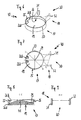
- Figur 1FIG. 1
- schematisch eine perspektivische Ansicht eines Kondensators, an dessen rechtem Kältemittelsammelkasten ein Sammler mit einer Trockner- und/oder Filterpatrone befestigt ist,1 is a schematic perspective view of a condenser, to whose right refrigerant collecting box a collector with a dryer and / or filter cartridge is attached;
- Figur 2FIG. 2
- schematisch eine perspektivische Ansicht einer Verschlusseinrichtung mit einem Verschlussdeckelbereich und mit Mitteln zum Halten des Sammlers an dem rechten Kältemittelsammelkasten,FIG. 2 schematically shows a perspective view of a closure device with a closure lid region and with means for holding the collector to the right-hand refrigerant collection box, FIG.
- Figur 3FIG. 3
-
schematisch eine Aufsicht der Verschlusseinrichtung aus der
Figur 2 ,schematically a plan view of the closure device of theFIG. 2 . - Figur 4FIG. 4
-
schematisch einen Querschnitt der Verschlusseinrichtung aus den
Figuren 2 und3 hinsichtlich des Verschlussdeckelbereiches,schematically a cross section of the closure device of theFigures 2 and3 regarding the closure lid area, - Figur 5FIG. 5
-
schematisch einen weiteren Querschnitt der Verschlusseinrichtung aus den
Figuren 2 bis 4 hinsichtlich der Haltemittel,schematically a further cross section of the closure device of theFIGS. 2 to 4 in terms of holding means, - Figur 6FIG. 6
- schematisch eine perspektivische Ansicht einer Halteeinrichtung mit einem alternativ gestalteten Verschlussdeckelbereich und mit alternativ gestalteten Mitteln zum Halten des Sammlers an dem rechten Kältemittelsammelkasten,2 schematically shows a perspective view of a holding device with an alternatively designed closure lid region and with alternatively configured means for holding the collector on the right-hand refrigerant collecting box,
- Figur 7FIG. 7
-
schematisch eine Aufsicht der Halteeinrichtung aus der
Figur 6 ,schematically a plan view of the holding device of theFIG. 6 . - Figur 8FIG. 8
-
schematisch einen Querschnitt der Halteeinrichtung aus den
Figuren 6 und 7 hinsichtlich des alternativ gestalteten Verschlussdeckelbereiches,schematically a cross section of the holding device from theFIGS. 6 and 7 with regard to the alternatively designed closure lid area, - Figur 9FIG. 9
-
schematisch einen weiteren Querschnitt der Halteeinrichtung aus den
Figuren 6 bis 8 hinsichtlich der alternativ gestalteten Haltemittel,schematically a further cross section of the holding device of theFIGS. 6 to 8 with regard to the alternatively designed holding means, - Figur 10FIG. 10
- schematisch eine perspektivische Ansicht einer alternativen Verschlusseinrichtung mit einem dickwandigen Verschlussdeckelbereich, mit einem Montagespalt und mit Mitteln zum Halten des Sammlers,FIG. 2 schematically shows a perspective view of an alternative closure device with a thick-walled closure lid region, with a mounting gap and with means for holding the collector, FIG.
- Figur 11FIG. 11
-
schematisch einen Querschnitt des Verschlussdeckelbereiches aus der
Figur 10 ,schematically a cross section of the closure lid region of theFIG. 10 . - Figur 12FIG. 12
-
schematisch eine Detailansicht des Montagespaltes aus den
Figuren 10 und 11 ,schematically a detailed view of the mounting gap from theFIGS. 10 and 11 . - Figur 13FIG. 13
- schematisch eine perspektivische Ansicht einer weiteren Verschlusseinrichtung mit einem dickwandigen Verschlussdeckelbereich, mit einem Montagespalt und mit einer zentralen Zubehöraufnahme, undschematically a perspective view of another closure device with a thick-walled closure lid area, with a mounting gap and with a central accessory receptacle, and
- Figur 14FIG. 14
-
schematisch einen Querschnitt des Verschlussdeckelbereiches aus der
Figur 13 .schematically a cross section of the closure lid region of theFIG. 13 ,
Der in der
Damit die Verschlusseinrichtung 14 eine derartige Doppelfunktion übernehmen kann, ist die Verschlusseinrichtung 14 im Wesentlichen in einen Verschlussdeckelbereich 17 und in einen Haltemittelbereich 18 unterteilbar. Der Verschlussdeckelbereich 17 weist im Wesentlichen einen Verschlussdeckel 19 und eine Aufnahme 20 für das axiales Ende 13 des Sammlers 11 auf.So that the
Damit die Verschlusseinrichtung 14, insbesondere im Verschlussdeckelbereich 17, besonders stabil ausgeführt ist, hat der Verschlussdeckel 19 einen veränderlichen Querschnitt 21 (siehe insbesondere
Die Aufnahme 20 wird in diesem Ausführungsbeispiel von einem konzentrisch um die Mitte 24 umlaufenden Kragen 25 gebildet, der einen radial nach innen gerichteten Innenbefestigungsbereich 26 bereit stellt, der mit einem Außenbefestigungsbereich 27 (siehe
Der radial nach innen gerichtete Innenbefestigungsbereich 26 ist in einen ersten Teilbereich 26A und in einen weiteren Teilbereich 26B unterteilt. Der erste Teilbereich 26A kann direkt an der Mantelfläche 16 des Sammlers 11 anliegen, so dass die Verschlusseinrichtung 14 vorteilhaft an dem Sammler 11 vormontiert werden kann. Der erste Teilbereich 26A kann vorliegend als eine umlaufende Montagefläche an der Verschlusseinrichtung 14 angesehen werden.The radially inwardly directed
Der weitere Teilbereich 26B kann radial nicht bis an die Mantelfläche 16 des Sammlers 11 heran reichen, so dass in einem montierten Zustand der Verschlusseinrichtung 14 ein Lötspalt (hier nicht eingezeichnet) zwischen dem weiteren Teilbereich 26B der Verschlusseinrichtung 14 und der Mantelfläche 16 des Sammlers 11 vorliegt, wodurch gewährleistet werden kann, dass immer eine ausreichende Menge Lot für eine flüssigkeitsdichte Lötverbindung in den Lötspalt fließen kann und zwischen der Verschlusseinrichtung 14 und dem Sammlers 11 zur Verfügung steht.The further
Beim Montieren wird die Verschlusseinrichtung 14 axial auf das axiale Ende 13 aufgesteckt, so dass der radial nach innen gerichtete Innenbefestigungsbereich 26 und der Außenbefestigungsbereich 27 des Sammlers 11 zur Überdeckung gelangen. Hierbei kann die Verschlusseinrichtung 14 derart auf das axiale Ende 13 aufgesteckt werden, bis der Verschlussdeckel 19 an das axiale Ende 13 anliegt. In dem vorliegenden Ausführungsbeispiel des Verschlussdeckels 14 sind hinsichtlich der Verstärkungsstege 22 und 23 Anlageflächen 29 (hier nur explizit beziffert) vorgesehen, an welche der Sammler 11 bei einer ordnungsgemäßen Verbindung zwischen der Verschlusseinrichtung 14 und dem Sammler 11 anstößt und die Verschlusseinrichtung 14 derart weit aufgesteckt ist, dass zwischen dem weiteren Teilbereich 26B des radial nach innen gerichteten Innenbefestigungsbereichs 26 und dem Außenbefestigungsbereich 27 immer ein Lötspalt vorhanden ist. Somit kann sich insbesondere ein verflüssigtes Lot vorteilhaft entlang des konzentrisch umlaufenden Kragens 25 verteilen, so dass die Gefahr einer Undichtigkeit auf Grund einer fehlerhaften Verlötung gegenüber dem Stand der Technik verringert ist.When mounting the
Hinsichtlich des Haltemittelbereiches 18 sind in diesem Ausführungsbeispiel Haltemittel 30 vorgesehen, die im Wesentlichen zwei Haltearme 31 und 32 sowie eine Abdeckung 33 umfassen. Die Haltearme 31 und 32 eigenen sich gut dazu, den runden Kältemittelsammelkasten 5 zu umgreifen. Mittels der Abdeckung kann der Kältemittelsammelkasten 5 zusätzlich vor axialen mechanischen Beanspruchungen geschützt werden. Da mittels der Haltemittel 30 keine flüssigkeitsführenden Bereiche des Kondensators 1 abgedichtet werden müssen, sind an diese Haltemittel 30 auch keine besonderen Ansprüche hinsichtlich ihrer Präzision zu stellen.With regard to the holding means
Der Sammler 11 kann mittels der in den
Der Verschlussdeckelbereich 17 umfasst im Wesentlichen einen Verschlussdeckel 19 und eine Aufnahme 20 zum Aufnehmen des axialen Endes 13 des Sammlers 11. Der Verschlussdeckel 19 weist einen veränderlichen Querschnitt 21 auf, der mittels einer Materialanhäufung 41 (siehe
Die Aufnahme 20 weist auch hier einen konzentrisch umlaufenden Kragen 25 mit einem radial nach innen gerichteten Innenbefestigungsbereich 26 auf, der mit dem Außenbefestigungsbereich 27 des Sammlers 11 kommunizieren kann. Auch hinsichtlich der Halteeinrichtung 40 ist der radial nach innen gerichteten Innenbefestigungsbereich 26 in einen ersten Teilbereich 26A und in einen weiteren Teilbereich 26B unterteilt, wobei der erste Teilbereich 26A direkt an der Mantelfläche 16 des Sammlers 11 anliegen und der weitere Teilbereich 26B nicht bis an die Mantelfläche 16 heran reichen kann, wodurch auch hinsichtlich der Halteeinrichtung 40 der vorteilhafte Lötspalt ausgebildet werden kann.The
Im Verschlussdeckelbereich 17 existieren Anlageflächen 29, an welche der Sammler 11 anstoßen kann, wenn die Halteeinrichtung 40 axial auf den Sammler 11 beziehungsweise axial auf das axialen Ende 13 des Sammlers 11 aufgesteckt werden.In the
Der Haltemittelbereich 18 weist ebenfalls Haltemittel 30 auf, die jedoch lediglich einen Haltearm 31 und einen weiteren Haltearm 32 umfassen. Vorliegend wird auf eine Abdeckung 33, wie noch bei der Verschlusseinrichtung 14 vorhanden, verzichtet, so dass die Halteeinrichtung 40 nahezu auf beliebiger Höhe an der Mantelfläche 16 des Sammlers 11 befestigt werden kann. Vorteilhafter Weise können hierdurch Sammler 11 an Kältemittelsammelkästen 5 beziehungsweise 6 angeordnet werden, die auch länger ausgebildet sind als der Sammler 11.The holding means
Die in der
Der Verschlussdeckelbereich 17 umfasst in diesem Ausführungsbeispiel einen Verschlussdeckel 19, der bis auf einen Montagespalt 51 vollständig massiv ausgebildet ist, so dass der Verschlussdeckel 19 einen im Wesentlichen konstant dicken Querschnitt 52 (siehe insbesondere
Zwar wird hierdurch die Verschlusseinrichtung 50 etwas schwerer, jedoch hat sie auf Grund des etwas dickeren Verschlussdeckels 19 eine höhere Festigkeit.Although this makes the
Der Montagespalt 51 läuft konzentrisch um die Mitte 24 des Verschlussdeckelbereiches 17 um. Innerhalb des Montagespaltes 51 ist der radial nach innen gerichtete Innenbefestigungsbereich 26 zu finden, der auch in diesem Ausführungsbeispiel in einen ersten Teilbereich 26A und in einen weiteren Teilbereich 26B unterteilt ist, wie besonders gut nach der Detaildarstellung 53 der
Mittels des Montagespaltes 51 kann die Verschlusseinrichtung 50 beim Aufsetzen auf das zweite axiale Ende 13 des Sammlers 11 wesentlich besser geführt werden, wodurch ein Verkanten der Verschlusseinrichtung 50 an dem Sammler 11 noch wirkungsvoller verhindert werden kann als hinsichtlich der zuvor erläuterten Ausführungsbeispiele.By means of the mounting
Darüber hinaus erhält die Verschlusseinrichtung 50 im Teilbereich 26A einen wesentlich festeren Sitz an dem Sammler 11, so dass die Gefahr einer Relativbewegung zwischen der Verschlusseinrichtung 50 und dem Sammler 11 vor und insbesondere auch während eines Lötprozesses kaum besteht.In addition, the
Weiter ist es auf Grund des Montagespaltes 51 möglich, den Sammler 11 zusätzlich auch an seiner Innenseite problemlos zu verlöten, da sich bei in den Montagespalt 51 eingestecktem axialen Ende 13 ein weiterer Lötspalt (hier nicht gezeigt) zwischen der Innenseite des Sammlers 11 und der Verschlussdeckelumfangsfläche 54 (siehe
Eine weitere vorteilhafte Verschlusseinrichtung 60 ist in den
Ansonsten ist in dem Verschlussdeckelbereich 17 zwischen einem umlaufenden Kragen 25 und dem Verschlussdeckel 19, der einen konstant dicken Querschnitt 52 hat, ein Montagespalt 51 vorgesehen, in welchem kragenseitig der radial nach innen gerichtete Innenbefestigungsbereich 26 mit seinen beiden Teilbereichen 26A und 26B platziert ist.Otherwise, in the
Neben dem Verschlussdeckelbereich 17 umfasst die Verschlusseinrichtung 60 auch wieder einen Haltemittelbereich 18 mit Haltemitteln 30, die einen ersten Haltearm 31 und einen weiteren Haltearm 32 umfassen.In addition to the
Claims (14)
Priority Applications (1)
| Application Number | Priority Date | Filing Date | Title |
|---|---|---|---|
| EP08290345.1A EP2108905B1 (en) | 2008-04-09 | 2008-04-09 | Condenser, in particular for a motor vehicle |
Applications Claiming Priority (1)
| Application Number | Priority Date | Filing Date | Title |
|---|---|---|---|
| EP08290345.1A EP2108905B1 (en) | 2008-04-09 | 2008-04-09 | Condenser, in particular for a motor vehicle |
Publications (2)
| Publication Number | Publication Date |
|---|---|
| EP2108905A1 true EP2108905A1 (en) | 2009-10-14 |
| EP2108905B1 EP2108905B1 (en) | 2017-01-11 |
Family
ID=39769434
Family Applications (1)
| Application Number | Title | Priority Date | Filing Date |
|---|---|---|---|
| EP08290345.1A Expired - Fee Related EP2108905B1 (en) | 2008-04-09 | 2008-04-09 | Condenser, in particular for a motor vehicle |
Country Status (1)
| Country | Link |
|---|---|
| EP (1) | EP2108905B1 (en) |
Cited By (3)
| Publication number | Priority date | Publication date | Assignee | Title |
|---|---|---|---|---|
| JP2013002732A (en) * | 2011-06-16 | 2013-01-07 | Calsonic Kansei Corp | Mounting structure of complex heat exchanger |
| CN114608225A (en) * | 2020-12-04 | 2022-06-10 | 马勒国际公司 | Closing plug for a collector of a refrigerant circuit |
| CN114963625A (en) * | 2021-02-24 | 2022-08-30 | 马勒国际公司 | Refrigerant circuit collector |
Citations (8)
| Publication number | Priority date | Publication date | Assignee | Title |
|---|---|---|---|---|
| JPH07180930A (en) * | 1993-10-12 | 1995-07-18 | Nippondenso Co Ltd | Liquid receiver integrated type refrigerant condenser |
| JPH10170102A (en) * | 1996-12-04 | 1998-06-26 | Showa Alum Corp | Liquid receiver integrated type condenser |
| JPH11223422A (en) * | 1990-09-12 | 1999-08-17 | Zexel:Kk | Receiver tank |
| DE9219200U1 (en) * | 1992-11-18 | 1999-12-09 | Behr Gmbh & Co | Air conditioning condenser |
| EP1310748A2 (en) * | 2001-11-08 | 2003-05-14 | Behr GmbH & Co. | Heat exchanger |
| US6694773B1 (en) * | 2003-01-29 | 2004-02-24 | Calsonickansei North America, Inc. | Condenser system with nondetachably coupled receiver |
| JP2004190955A (en) * | 2002-12-11 | 2004-07-08 | Calsonic Kansei Corp | Condenser |
| DE102005005187A1 (en) | 2005-02-03 | 2006-08-10 | Behr Gmbh & Co. Kg | Condenser for an air conditioning system, in particular a motor vehicle |
-
2008
- 2008-04-09 EP EP08290345.1A patent/EP2108905B1/en not_active Expired - Fee Related
Patent Citations (8)
| Publication number | Priority date | Publication date | Assignee | Title |
|---|---|---|---|---|
| JPH11223422A (en) * | 1990-09-12 | 1999-08-17 | Zexel:Kk | Receiver tank |
| DE9219200U1 (en) * | 1992-11-18 | 1999-12-09 | Behr Gmbh & Co | Air conditioning condenser |
| JPH07180930A (en) * | 1993-10-12 | 1995-07-18 | Nippondenso Co Ltd | Liquid receiver integrated type refrigerant condenser |
| JPH10170102A (en) * | 1996-12-04 | 1998-06-26 | Showa Alum Corp | Liquid receiver integrated type condenser |
| EP1310748A2 (en) * | 2001-11-08 | 2003-05-14 | Behr GmbH & Co. | Heat exchanger |
| JP2004190955A (en) * | 2002-12-11 | 2004-07-08 | Calsonic Kansei Corp | Condenser |
| US6694773B1 (en) * | 2003-01-29 | 2004-02-24 | Calsonickansei North America, Inc. | Condenser system with nondetachably coupled receiver |
| DE102005005187A1 (en) | 2005-02-03 | 2006-08-10 | Behr Gmbh & Co. Kg | Condenser for an air conditioning system, in particular a motor vehicle |
Cited By (3)
| Publication number | Priority date | Publication date | Assignee | Title |
|---|---|---|---|---|
| JP2013002732A (en) * | 2011-06-16 | 2013-01-07 | Calsonic Kansei Corp | Mounting structure of complex heat exchanger |
| CN114608225A (en) * | 2020-12-04 | 2022-06-10 | 马勒国际公司 | Closing plug for a collector of a refrigerant circuit |
| CN114963625A (en) * | 2021-02-24 | 2022-08-30 | 马勒国际公司 | Refrigerant circuit collector |
Also Published As
| Publication number | Publication date |
|---|---|
| EP2108905B1 (en) | 2017-01-11 |
Similar Documents
| Publication | Publication Date | Title |
|---|---|---|
| EP0666461B2 (en) | Pipe connection for a water casing of a motor vehicle heat exchanger | |
| EP1333219A1 (en) | Quick acting coupling | |
| DE3203356A1 (en) | Heat exchanger | |
| DE4332619A1 (en) | oil cooler | |
| DE19805439B4 (en) | Process for producing a stacked disk heat exchanger and heat exchanger produced thereby | |
| DE112013005025T5 (en) | heat exchangers | |
| EP2108905B1 (en) | Condenser, in particular for a motor vehicle | |
| DE102005048772A1 (en) | Heat exchanger with integrated intermediate tank / dryer sleeve | |
| DE10353160A1 (en) | Heat exchanger and sump / dryer assembly for heat exchangers | |
| DE3312613A1 (en) | Fuel filter, especially for diesel fuel | |
| DE4106296C2 (en) | Heat exchangers, in particular water / air coolers for internal combustion engines | |
| EP1890102B1 (en) | Domed header plate for the tank of a heat exchanger | |
| DE202012101622U1 (en) | Heat exchanger | |
| DE102010001543A1 (en) | Heat exchanger, particularly condenser for motor vehicle air conditioning system, comprises external collecting container, which serves as reservoir for fluid flowing through heat exchanger | |
| DE102007055328A1 (en) | pipe connection | |
| WO2021013633A1 (en) | Refrigerating appliance and water outlet arrangement for a refrigerating appliance | |
| DE102006058386A1 (en) | Collecting box for e.g. coolant cooler of motor vehicle, has connecting piece which is arranged in upper side of box and is connected with box by bayonet joint, where piece and box can be sealed by sealing unit that is formed as O-ring | |
| DE102007051512A1 (en) | Dryer for air conditioning system of vehicle, has insert for filtering and drying refrigerant arranged at inner side of housing between openings, where insert is provided with housing region with larger diameter than another housing region | |
| EP0099472A2 (en) | Liquid filter | |
| EP1682831B1 (en) | Heat exchanger | |
| DE102012222664A1 (en) | capacitor | |
| EP2818817B1 (en) | Condenser module | |
| WO1995003519A1 (en) | Heat store, especially latent heat store | |
| DE2737724C2 (en) | Closure insert with a pipe socket in a container wall | |
| DE102007063641B4 (en) | Connection arrangement for the installation area |
Legal Events
| Date | Code | Title | Description |
|---|---|---|---|
| PUAI | Public reference made under article 153(3) epc to a published international application that has entered the european phase |
Free format text: ORIGINAL CODE: 0009012 |
|
| AK | Designated contracting states |
Kind code of ref document: A1 Designated state(s): AT BE BG CH CY CZ DE DK EE ES FI FR GB GR HR HU IE IS IT LI LT LU LV MC MT NL NO PL PT RO SE SI SK TR |
|
| AX | Request for extension of the european patent |
Extension state: AL BA MK RS |
|
| 17P | Request for examination filed |
Effective date: 20100414 |
|
| AKX | Designation fees paid |
Designated state(s): DE FR |
|
| 17Q | First examination report despatched |
Effective date: 20100709 |
|
| RAP3 | Party data changed (applicant data changed or rights of an application transferred) |
Owner name: BEHR FRANCE HAMBACH S.A.R.L. |
|
| RAP1 | Party data changed (applicant data changed or rights of an application transferred) |
Owner name: MAHLE BEHR FRANCE HAMBACH S.A.S |
|
| GRAP | Despatch of communication of intention to grant a patent |
Free format text: ORIGINAL CODE: EPIDOSNIGR1 |
|
| INTG | Intention to grant announced |
Effective date: 20160701 |
|
| GRAS | Grant fee paid |
Free format text: ORIGINAL CODE: EPIDOSNIGR3 |
|
| GRAJ | Information related to disapproval of communication of intention to grant by the applicant or resumption of examination proceedings by the epo deleted |
Free format text: ORIGINAL CODE: EPIDOSDIGR1 |
|
| GRAL | Information related to payment of fee for publishing/printing deleted |
Free format text: ORIGINAL CODE: EPIDOSDIGR3 |
|
| GRAR | Information related to intention to grant a patent recorded |
Free format text: ORIGINAL CODE: EPIDOSNIGR71 |
|
| GRAA | (expected) grant |
Free format text: ORIGINAL CODE: 0009210 |
|
| INTC | Intention to grant announced (deleted) | ||
| RIN1 | Information on inventor provided before grant (corrected) |
Inventor name: KIHN, HUBERT Inventor name: KACZMAREK, FABRICE Inventor name: MINE, STEVE Inventor name: VAN HAAREN, STEPHANE |
|
| AK | Designated contracting states |
Kind code of ref document: B1 Designated state(s): DE FR |
|
| INTG | Intention to grant announced |
Effective date: 20161202 |
|
| REG | Reference to a national code |
Ref country code: DE Ref legal event code: R096 Ref document number: 502008014945 Country of ref document: DE |
|
| REG | Reference to a national code |
Ref country code: DE Ref legal event code: R097 Ref document number: 502008014945 Country of ref document: DE |
|
| REG | Reference to a national code |
Ref country code: DE Ref legal event code: R119 Ref document number: 502008014945 Country of ref document: DE |
|
| PLBE | No opposition filed within time limit |
Free format text: ORIGINAL CODE: 0009261 |
|
| STAA | Information on the status of an ep patent application or granted ep patent |
Free format text: STATUS: NO OPPOSITION FILED WITHIN TIME LIMIT |
|
| 26N | No opposition filed |
Effective date: 20171012 |
|
| REG | Reference to a national code |
Ref country code: FR Ref legal event code: ST Effective date: 20171229 |
|
| PG25 | Lapsed in a contracting state [announced via postgrant information from national office to epo] |
Ref country code: DE Free format text: LAPSE BECAUSE OF NON-PAYMENT OF DUE FEES Effective date: 20171103 Ref country code: FR Free format text: LAPSE BECAUSE OF NON-PAYMENT OF DUE FEES Effective date: 20170502 |