EP2108759B1 - Muffenverbindung für Betonbewehrungsstäbe - Google Patents
Muffenverbindung für Betonbewehrungsstäbe Download PDFInfo
- Publication number
- EP2108759B1 EP2108759B1 EP09001737.7A EP09001737A EP2108759B1 EP 2108759 B1 EP2108759 B1 EP 2108759B1 EP 09001737 A EP09001737 A EP 09001737A EP 2108759 B1 EP2108759 B1 EP 2108759B1
- Authority
- EP
- European Patent Office
- Prior art keywords
- reinforcing bar
- recess
- concrete
- sleeve
- sleeve connector
- Prior art date
- Legal status (The legal status is an assumption and is not a legal conclusion. Google has not performed a legal analysis and makes no representation as to the accuracy of the status listed.)
- Not-in-force
Links
- 230000002787 reinforcement Effects 0.000 title description 13
- 230000003014 reinforcing effect Effects 0.000 claims description 52
- 239000000463 material Substances 0.000 claims description 21
- 230000000295 complement effect Effects 0.000 claims description 18
- 229910000831 Steel Inorganic materials 0.000 claims description 7
- 239000010959 steel Substances 0.000 claims description 7
- 239000000853 adhesive Substances 0.000 claims description 4
- 230000001070 adhesive effect Effects 0.000 claims description 4
- 239000011295 pitch Substances 0.000 claims description 3
- 229920002430 Fibre-reinforced plastic Polymers 0.000 claims description 2
- 239000011151 fibre-reinforced plastic Substances 0.000 claims description 2
- 239000011152 fibreglass Substances 0.000 description 9
- 238000011161 development Methods 0.000 description 7
- 230000018109 developmental process Effects 0.000 description 7
- 229910001294 Reinforcing steel Inorganic materials 0.000 description 4
- 230000004913 activation Effects 0.000 description 4
- 230000009467 reduction Effects 0.000 description 3
- 230000008602 contraction Effects 0.000 description 2
- 239000003365 glass fiber Substances 0.000 description 2
- 230000003993 interaction Effects 0.000 description 2
- 239000010935 stainless steel Substances 0.000 description 2
- 229910001220 stainless steel Inorganic materials 0.000 description 2
- 229920003002 synthetic resin Polymers 0.000 description 2
- 239000000057 synthetic resin Substances 0.000 description 2
- 102100040287 GTP cyclohydrolase 1 feedback regulatory protein Human genes 0.000 description 1
- 101710185324 GTP cyclohydrolase 1 feedback regulatory protein Proteins 0.000 description 1
- 238000004026 adhesive bonding Methods 0.000 description 1
- 230000005540 biological transmission Effects 0.000 description 1
- 230000015572 biosynthetic process Effects 0.000 description 1
- 150000001875 compounds Chemical class 0.000 description 1
- 238000010276 construction Methods 0.000 description 1
- 230000003247 decreasing effect Effects 0.000 description 1
- 230000001419 dependent effect Effects 0.000 description 1
- 230000013011 mating Effects 0.000 description 1
- 230000001404 mediated effect Effects 0.000 description 1
- 239000012720 thermal barrier coating Substances 0.000 description 1
- 230000005641 tunneling Effects 0.000 description 1
Images


Classifications
-
- E—FIXED CONSTRUCTIONS
- E04—BUILDING
- E04C—STRUCTURAL ELEMENTS; BUILDING MATERIALS
- E04C5/00—Reinforcing elements, e.g. for concrete; Auxiliary elements therefor
- E04C5/16—Auxiliary parts for reinforcements, e.g. connectors, spacers, stirrups
- E04C5/162—Connectors or means for connecting parts for reinforcements
- E04C5/163—Connectors or means for connecting parts for reinforcements the reinforcements running in one single direction
- E04C5/165—Coaxial connection by means of sleeves
Definitions
- the present invention relates to a socket joint for a first concrete reinforcing bar and a second concrete reinforcing bar, which first concrete reinforcing bar and which second concrete reinforcing bar are formed of materials having mutually different elastic moduli, in particular for a reinforcing steel bar and a bar of fiberglass reinforced plastic, wherein the concrete reinforcing bars each having a connecting end are connected to a sleeve part having at least a first recess for receiving the first concrete reinforcing bar, which first concrete reinforcing bar has a relatively lower modulus of elasticity, and another junction, in particular a second recess, for the second concrete reinforcing bar, which second concrete reinforcing bar has a relatively higher modulus of elasticity ,
- the sleeve parts may also be formed in two parts in the manner of a Male- and a female-female part, such as from the EP 1 277 892 A1 or the DE 201 10 720 known.
- the concrete reinforcing bars to be connected and the sleeve part or the sleeve parts are made of steel and thus have essentially the same material properties, in particular elasticity modules, so that there is generally no relative slip between the connected components under load the emergence of which in principle a modulus of elasticity difference is required.
- glass fiber reinforced plastic in rod form for concrete reinforcement which are characterized in particular with respect to stainless steel by a lower thermal conductivity and reduced procurement costs.
- said glass fiber rods are relatively easy to drill or machine, resulting in further advantages in the application, especially in tunneling.
- the present invention seeks to further develop a socket joint of the type mentioned in that a secure and firm connection of concrete reinforcing bars is made possible, which consist of materials with mutually different moduli of elasticity.
- the invention achieves the object by means of a socket connection with the features of the appended patent claim 1.
- a socket joint for a first concrete reinforcing bar and a second concrete reinforcing bar which first concrete reinforcing bar and which second concrete reinforcing bar are formed of materials with different moduli of elasticity, in particular for a reinforcing steel bar and a bar of fiberglass reinforced plastic, wherein the concrete reinforcing bars each having a connecting end with a Clamp part are connected, which has at least a first recess for receiving the first concrete reinforcing bar, which first concrete reinforcing rod has a relatively lower modulus of elasticity, and another joint, in particular a second recess for the second concrete reinforcing bar, which second concrete reinforcing rod has a relatively higher modulus of elasticity thereby characterized in that within the first recess at least one additional internal structure in the form of a longitudinal direction Chse of the socket connection is formed in the first recess projecting geometric body, which cooperates with complementary structures on the inserted into the socket part connecting end of the first concrete reinforcing bar surface
- the said additional activation together with the reduced overlap length, contributes to a significant reduction in slip, resulting in a secure and firm connection between the sleeve part and said concrete reinforcing bar, and then at the other end of the sleeve part another concrete reinforcing bar can be connected to create the complete sleeve connection.
- Said second recess for receiving the second concrete reinforcing bar according to the invention is not absolutely necessary.
- the inner structure may be formed in a development of the present invention as a projecting into the first recess geometric body, such as a truncated cone, a hollow circular cylinder section, a number of fins, pins or the like.
- the complementary structures at the connecting end of the first concrete reinforcing bar are preferably formed in the curing state of the GFRP material accordingly in this.
- a preferred development of the invention consists in that the sleeve part in the region of the first recess has a reduced material thickness compared to the rest of the sleeve part, in particular a reduced outside diameter. This measure also contributes to avoiding slippage.
- the sleeve part in the region of the first recess tapers substantially frustoconically towards its end, wherein, however, the taper is also not limited to straight or flat flanks of the sleeve part.
- the outer flanks of the sleeve part in the tapering region can also be formed in particular concavely curved.
- the inner structure is formed and / or arranged symmetrically with respect to the longitudinal axis of the sleeve part or of the entire sleeve connection.
- the inner structure may be formed in a development of the present invention rotationally symmetrical relative to the longitudinal axis of the sleeve part or the sleeve connection.
- the inner wall of the first recess is formed complementary to an opposite wall of the inner structure.
- said inner wall of the first recess and an opposite wall of the inner structure are respectively oriented parallel to the longitudinal axis of the sleeve part and the sleeve connection.
- an extremely preferred development of the present invention provides that at least one thread is provided at the connecting end of the first concrete reinforcing bar and at least one corresponding counter-thread is provided in the first recess of the sleeve part and / or on the inner structure.
- the recess has a first internal thread and the internal structure has a first external thread.
- the connecting end of the concrete reinforcing rod has first an external thread, which cooperates with the first internal thread of the sleeve part, and a second internal thread, which cooperates with the external thread of the inner structure of the sleeve part.
- the thread and the corresponding mating thread have different pitches and / or a certain offset to each other, that is, "arranged on a gap", to better distribute the adhesive.
- another preferred embodiment of the present invention provides that the sleeve part is formed in a material which substantially corresponds to the material of the second concrete reinforcement rod.
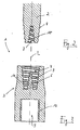
- FIG. 1 shows an embodiment of the socket joint according to the invention for concrete reinforcement rods of materials with mutually different elastic moduli, which is designated as a whole by the reference numeral 1.
- the socket joint 1 is in FIG. 1 shown in the separated state, in which the concrete reinforcing bars, of which in FIG. 1 only one is shown explicitly, not inserted into the actual sleeve part 3.
- the socket joint 1 is particularly suitable for connecting a reinforcing steel bar with a rod 2 made of glass fiber reinforced plastic (GRP), since the materials mentioned have particularly different elastic moduli.
- GRP glass fiber reinforced plastic
- the sleeve part 3 has for this purpose a first recess 4 and a per se optional second recess 5, which at opposite sides Ends of the sleeve part 3 are formed.
- the first recess 4 serves to receive the illustrated concrete reinforcing bar 2, which has the relatively lower modulus of elasticity.
- the second recess 5 serves to receive a second concrete reinforcement bar (not shown), which has the higher modulus of elasticity with respect to the concrete reinforcement bar 2.
- the sleeve part 3 is preferably formed in a material which, in particular with regard to the modulus of elasticity, has comparable properties to the material of the second concrete reinforcement bar, not shown, wherein the said material is preferably a suitable steel.
- the sleeve part 3 and the second reinforcing rod can alternatively also be connected to one another by simple gluing, so that correspondingly no second recess is required.
- the sleeve part 3 in the region of the first recess 4 has a reduced material thickness compared to the rest of the sleeve part 3.
- the sleeve part 3 is formed in said region with a reduced outer diameter decreasing towards the corresponding end of the sleeve part 3.
- the embodiment of the socket joint 1 shown further provides that within the first recess 4 an additional internal structure 6 is formed, which in the present case has an in represents the first recess 4 projecting truncated cone, in particular the sectional view in FIG. 3 can be seen.
- a structure 7 complementary to the internal structure 6 of the sleeve part 3 is designed in the form of a frusto-conical recess, so that said structures 6, 7 cooperate flatly when the concrete reinforcing bar 2 is inserted into the sleeve part 3 ,
- surface interaction means in this case that on the inner structure 6 and the complementary structure 7 an enlarged contact or contact surface between the concrete reinforcement bar 2 and the sleeve part 3 is created, so that despite the relatively short overlap length UL improved material activation for voltage transmission caused, which in turn contributes to slip reduction.
- the inner structure 6 of the sleeve part 3 and the complementary structure 7 of the concrete reinforcing bar 2 are arranged or formed symmetrically to the longitudinal axis L of the sleeve joint 1 shown.
- the concrete reinforcing bar 2 which is preferably formed in said glass fiber reinforced plastic (GRP), has a conically tapered connection end, wherein the first recess 4 of the sleeve part 3 is formed correspondingly complementary.
- This special shape further contributes to an ideally linear load profile in the contact or connection area.
- the concrete reinforcing bar 2 at its connection end, first an external thread 8 and the sleeve part 3 in the region of the first recess 4 has a corresponding internal thread 9.
- the concrete reinforcement rod 2 has in the region of the complementary structure 7 an additional internal thread 10 (cf. FIG. 2 ), while the inner structure 6 of the sleeve part 3 a correspondingly complementary external thread 11 (see. FIG. 3 ) is provided.
- the threads of the concrete reinforcing bar 2 on the one hand and the sleeve part 3 on the other hand can be offset from each other and / or formed differently with respect to their pitches to ensure a secure connection of said components - especially if these by introducing an adhesive, such as synthetic resin, in the first Recess mediated or supported.
- a thread 12 is provided, which may be formed for connection to the concrete reinforcing bar, not shown in a conventional manner.
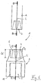
- FIGS. 4 and 5 show the above with reference to the FIGS. 1 to 3 explained in detail embodiment of the socket joint according to the invention in the assembled state and under suggestion of the second concrete reinforcing bar 2 ', with the corresponding figures otherwise not be discussed.
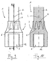
- FIGS. 6 to 10 show a further embodiment of the socket joint 1 according to the invention, in the present case for the sake of brevity only on the essential differences from the above-detailed embodiment according to the FIGS. 1 to 5 will be discussed in more detail.
- the sleeve part 3 and the concrete reinforcing bar 2 are formed with an even shorter overlapping area ÜL '.
- the cross-section or radius decrease a of the sleeve part is also according to FIG. 6 significantly more pronounced than in the FIGS. 1 to 5 ,
- an inner structure 6 is formed in the region of the first exception 4 of the sleeve part 3, which in cross-section (see. FIG. 8 ) is again formed as a truncated cone as a whole, but in addition also has a central, also frusto-conical recess 13, which just vice versa is oriented to the truncated cone-like course of the remaining inner structure 6.
- the structure 7 at the connection end of the concrete reinforcing bar 2 is in turn formed complementary to the above-described inner structure 6 and consists for this purpose of a conical recess (see. FIGS. 1 to 5 ), in which, however, a conical projection 14 which projects in the opposite direction, which is designed to engage in the additional recess 13 of the sleeve part 3, projects centrally.
- the concrete reinforcing rod 2 does not taper at its connection end, and the outer wall 15 of the recess 4 of the sleeve part 3 also extends in a complementary manner parallel to the longitudinal axis L of the socket joint 1.
- FIGS. 9 and 10 show the embodiment of the sleeve joint 1 described above in detail in the assembled state.
- FIGS. 11 to 15 show a further embodiment of the socket joint 1 according to the invention, again in turn only essential differences compared to the embodiments already described will be discussed.
- FIGS. 11 to 15 The in the FIGS. 11 to 15 The embodiment shown essentially corresponds to that according to FIGS. 6 to 10 , where only the projecting Structures in the region of the first recess 4 of the sleeve part 3, which form said inner structure 6, are formed with walls 16, 17 oriented parallel to the longitudinal axis L of the socket joint 1. Overall, this results in the appearance of a hollow circular cylindrical portion for the inner structure 6, while the structure 7 is formed correspondingly complementary at the terminal end of the concrete reinforcing bar 2, as shown in the figures.
- threaded means can be provided, which in the FIGS. 11 to 15 is not explicitly shown.
- the present invention is not limited to the rotationally symmetrical embodiments described above by way of example.
- the inner structure 6 may also be formed in the form of a preferably uniform grid of lamellae, pins or the like, which cooperate with corresponding complementary structures (receptacles) at the attachment end of the concrete reinforcement bar 2 in order to create the largest possible contact surface.
Landscapes
- Engineering & Computer Science (AREA)
- Architecture (AREA)
- Civil Engineering (AREA)
- Structural Engineering (AREA)
- Reinforcement Elements For Buildings (AREA)
- Joining Of Building Structures In Genera (AREA)
Description
- Die vorliegende Erfindung betrifft eine Muffenverbindung für einen ersten Betonbewehrungsstab und einen zweiten Betonbewehrungsstab, welcher erste Betonbewehrungsstab und welcher zweite Betonbewehrungsstab aus Materialien mit voneinander verschiedenen Elastizitätsmodulen gebildet sind, insbesondere für einen Betonstahlstab und einen Stab aus glasfaserverstärktem Kunststoff, bei der die Betonbewehrungsstäbe jeweils mit einem Verbindungsende mit einem Muffenteil verbunden sind, welches zumindest eine erste Ausnehmung aufweist zum Aufnehmen des ersten Betonbewehrungsstabs, welcher erste Betonbewehrungsstab einen relativ niedrigeren Elastizitätsmodul aufweist, und eine weitere Verbindungsstelle, insbesondere eine zweite Ausnehmung, für den zweiten Betonbewehrungsstab, welcher zweite Betonbewehrungsstab einen relativ höheren Elastizitätsmodul aufweist.
- Derartige Muffenverbindungen bzw. Muffenteile zum Schaffen derartiger Verbindungen sind bekannt. Dabei können die Muffenteile auch zweigeteilt nach Art eines Male- und eines Female-Muffenteils ausgebildet sein, wie beispielsweise aus der
EP 1 277 892 A1 oder derDE 201 10 720 bekannt. - In der Regel bestehen dabei die zu verbindenden Betonbewehrungsstäbe sowie das Muffenteil bzw. die Muffenteile aus Stahl und weisen somit im Wesentlichen gleiche Materialeigenschaften, insbesondere Elastizitätsmodule auf, so dass es in der Regel unter Last nicht zu einem relativen Schlupf zwischen den verbundenen Bauteilen kommt, für dessen Entstehen grundsätzlich eine Elastizitätsmodul-Differenz erforderlich ist.
- Die Anmelderin hat jedoch in der Vergangenheit verstärkt anstelle von Stahl, insbesondere Edelstahl, auch glasfaserverstärkte Kunststoff in Stabform zur Betonbewehrung eingesetzt, welche sich insbesondere gegenüber Edelstahl durch eine geringere Wärmeleitfähigkeit und reduzierte Beschaffungskosten auszeichnen. Außerdem sind die genannten Glasfaserstäbe relativ leicht durchbohrbar oder zerspanbar, was weitere Vorteile bei der Anwendung ergibt, insbesondere im Tunnelbau.
- Ein besonderes Problem entsteht jedoch an der Verbindungsstelle zwischen den genannten Glasfaserstäben und herkömmlichen Betonstahlstäben, da die genannten glasfaserverstärkten Kunststoff einerseits und Stahl andererseits stark unterschiedliche Elastizitätsmodule aufweisen, die sich in der Praxis beispielsweise um einen Faktor 3,5 unterscheiden können. Wie oben bereits ausgeführt, kann eine derartige Elastizitätsmodul-Differenz zu einem Schlupf an der Verbindungsstelle führen, so dass derartige Verbindungen keine optimale Belastungsfestigkeit aufweisen. Da zur Ermittlung des Schlupfs der Quotient aus Spannung und Elastizitätsmodul über den Weg integriert wird, ist auch eine vergrößerte Überlappungslänge im Verbindungsbereich von GFK und Stahl durch ein entsprechend ausgebildetes Muffenteil nicht hilfreich, sondern vielmehr eher kontraproduktiv.
- Aus der
WO 2005/035892 A1 ist eine Verbindung zwischen einem Gewindestab aus faserverstärktem Kunststoff und einer Gewindehülse bekannt, die eine zusätzliche Wärmedämmschicht umfasst. - Hiervon ausgehend liegt der Erfindung die Aufgabe zugrunde, eine Muffenverbindung der eingangs genannten Art dahingehend weiterzuentwickeln, dass eine sichere und feste Verbindung von Betonbewehrungsstäben ermöglicht wird, die aus Materialien mit voneinander verschiedenen Elastizitätsmodulen bestehen.
- Die Erfindung löst die Aufgabe mittels einer Muffenverbindung mit den Merkmalen des beigefügten Patentanspruchs 1.
- Vorteilhafte Weiterbildungen des Erfindungsgegenstands sind in den Unteransprüchen angegebenen, deren Wortlaut hiermit durch ausdrückliche Bezugnahme in die Beschreibung aufgenommen wird, um unnötige Textwiederholungen zu vermeiden.
- Erfindungsgemäß ist eine Muffenverbindung für einen ersten Betonbewehrungsstab und einen zweiten Betonbewehrungsstab, welcher erste Betonbewehrungsstab und welcher zweite Betonbewehrungsstab aus Materialien mit voneinander verschiedenen Elastizitätsmodulen gebildet sind, insbesondere für einen Betonstahlstab und einen Stab aus glasfaserverstärktem Kunststoff, bei der die Betonbewehrungsstäbe jeweils mit einem Verbindungsende mit einem Muffenteil verbunden sind, welches zumindest eine erste Ausnehmung aufweist zum Aufnehmen des ersten Betonbewehrungsstabs, welcher erste Betonbewehrungsstabs einen relativ niedrigeren Elastizitätsmodul aufweist, und eine weitere Verbindungsstelle, insbesondere eine zweite Ausnehmung, für den zweiten Betonbewehrungsstab, welcher zweite Betonbewehrungsstab einen relativ höheren Elastizitätsmodul aufweist, dadurch gekennzeichnet, dass innerhalb der ersten Ausnehmung wenigstens eine zusätzliche Innenstruktur in Form eines in Richtung einer Längsachse der Muffenverbindung in die erste Ausnehmung hineinragenden geometrischen Körpers ausgebildet ist, die mit komplementären Strukturen an dem in das Muffenteil eingesetzten Verbindungsende des ersten Betonbewehrungsstabs flächig zusammenwirkt.
- Nach einem Grundgedanken der vorliegenden Erfindung wird durch das Ausbilden der genannten Innenstruktur des Muffenteils und den dazu komplementären Strukturen am Verbindungsende des ersten Betonbewehrungsstabs eine vergrößerte Kontakt- oder Aktivierungsfläche zwischen dem Betonbewehrungsstab und dem Muffenteil geschaffen, so dass sich ein verbessertes Belastungsverhalten ergibt, welches insbesondere mit einer gegenüber herkömmlichen Konstruktionen deutlichen Reduzierung der Überlappungslänge zwischen Muffenteil und eingesetztem Betonbewehrungsstab einhergehen kann. Die genannte zusätzliche Aktivierung trägt zusammen mit der verringerten Überlappungslänge zu einer deutlichen Verringerung des Schlupfs bei, so dass sich eine sichere und feste Verbindung zwischen Muffenteil und dem genannten Betonbewehrungsstab ergibt, wobei anschließend am anderen Ende des Muffenteils ein weiterer Betonbewehrungsstab zur Schaffung der vollständigen Muffenverbindung anschließbar ist.
- Die genannte zweite Ausnehmung zum Aufnehmen des zweiten Betonbewehrungsstabs ist erfindungsgemäß nicht unbedingt erforderlich. Beispielsweise kann alternativ auch vorgesehen sein, ein Muffenteil nur mit erster Ausnehmung auf das Verbindungsende des zweiten Bewehrungsstabs aufzukleben.
- Die Innenstruktur kann in Weiterbildung der vorliegenden Erfindung als ein in die erste Ausnehmung hineinragender geometrischer Körper, wie ein Kegelstumpf, ein hohler Kreiszylinderabschnitt, eine Anzahl von Lamellen, Stiften oder dergleichen, ausgebildet sein. Die komplementären Strukturen am Verbindungsende des ersten Betonbewehrungsstabs werden vorzugsweise im Aushärtungszustand des GFK-Materials entsprechend in diesem ausgebildet.
- Eine bevorzugte Weiterbildung der Erfindung besteht darin, dass das Muffenteil im Bereich der ersten Ausnehmung eine gegenüber dem restlichen Muffenteil reduzierte Materialstärke, insbesondere einen reduzierten Außendurchmesser aufweist. Auch diese Maßnahme trägt mit zu einer Schlupfvermeidung bei.
- Eine andere Weiterbildung der vorliegenden Erfindung sieht vor, dass sich das Muffenteil im Bereich der ersten Ausnehmung zwecks Reduzierung seiner Materialstärke zu seinem Ende hin außen im Wesentlichen kegelstumpfartig verjüngt, wobei die Verjüngung allerdings auch nicht auf gerade oder ebene Flanken des Muffenteils beschränkt ist. Beispielsweise können die Außenflanken des Muffenteils im Verjüngungsbereich auch insbesondere konkav gekrümmt ausgebildet sein.
- Vorteilhafterweise ist die Innenstruktur symmetrisch bezogen auf die Längsachse des Muffenteils bzw. der gesamten Muffenverbindung ausgebildet und/oder angeordnet. Speziell kann die Innenstruktur in Weiterbildung der vorliegenden Erfindung rotationssymmetrisch bezogen auf die Längsachse des Muffenteils bzw. der Muffenverbindung ausgebildet sein.
- Eine andere Weiterbildung des Erfindungsgegenstands sieht vor, dass die Innenwand der ersten Ausnehmung komplementär zu einer gegenüberliegenden Wand der Innenstruktur ausgebildet ist. Hierunter fallen insbesondere Ausgestaltungen, bei denen die genannte Innenwand der ersten Ausnehmung und eine gegenüberliegende Wand der Innenstruktur jeweils parallel zur Längsachse des Muffenteils bzw. der Muffenverbindung orientiert sind. Allerdings ist es auch möglich, sowohl die genannte Innenwand als auch die gegenüberliegende Wand der Innenstruktur bezogen auf die Längsachse der Anordnung geneigt auszurichten.
- Zur Erhöhung der Verbindungssicherheit sieht eine äußerst bevorzugte Weiterbildung der vorliegenden Erfindung vor, dass an dem Verbindungsende des ersten Betonbewehrungsstabs wenigstens ein Gewinde und in der ersten Ausnehmung des Muffenteils und/oder an der Innenstruktur wenigstens ein entsprechendes Gegengewinde vorgesehen ist. Vorteilhafterweise weist die Ausnehmung ein erstes Innengewinde und die Innenstruktur ein erstes Außengewinde auf. Komplementär hierzu besitzt das Verbindungsende des Betonbewehrungsstabs zunächst ein Außengewinde, welches mit dem ersten Innengewinde des Muffenteils zusammenwirkt, sowie ein zweites Innengewinde, welches mit dem Außengewinde der Innenstruktur des Muffenteils zusammenwirkt.
- Insbesondere wenn bei der Ausbildung der Muffenverbindung Klebstoff, wie Kunstharz oder dergleichen, zum Einsatz kommt, ist es vorteilhaft, wenn das genannte Gewinde und das entsprechende Gegengewinde unterschiedliche Ganghöhen und/oder einen gewissen Versatz zueinander aufweisen, das heißt "auf Lücke" angeordnet sind, um das Klebemittel besser zu verteilen.
- Um das Auftreten einer Schlupfproblematik am anderen Ende des Muffenteils zu vermeiden, sieht eine andere, bevorzugte Weiterbildung der vorliegenden Erfindung vor, dass das Muffenteil in einem Material ausgebildet ist, welches im Wesentlichen dem Material des zweiten Betonbewehrungsstabs entspricht.
- Weitere Eigenschaften und Vorteile der vorliegenden Erfindung ergeben sich aus der nachfolgenden Beschreibung von Ausführungsbeispielen anhand der Zeichnung. Es zeigt:
- Figur 1
- eine erste Ausgestaltung der erfindungsgemäßen Muffenverbindung im getrennten Zustand;
- Figur 2
- einen Schnitt entlang der Linie B-B in
Figur 1 ; - Figur 3
- einen Schnitt entlang der Linie C-C in
Figur 1 ; - Figur 4
- die Ausgestaltung der erfindungsgemäßen Muffenverbindung gemäß
Figur 1 im zusammengesetzten Zustand; - Figur 5
- einen Schnitt entlang der Linie A-A in
Figur 4 ; - Figur 6
- eine weitere Ausgestaltung der erfindungsgemäßen Muffenverbindung im getrennten Zustand;
- Figur 7
- einen Schnitt entlang der Linie B-B in
Figur 6 ; - Figur 8
- einen Schnitt entlang der Linie C-C in
Figur 6 ; - Figur 9
- die Muffenverbindung gemäß
Figur 6 im zusammengesetzten Zustand; - Figur 10
- einen Schnitt entlang der Linie A-A in
Figur 9 ; - Figur 11
- eine weitere Ausgestaltung der erfindungsgemäßen Muffenverbindung im getrennten Zustand;
- Figur 12
- einen Schnitt entlang der Linie B-B in
Figur 11 ; - Figur 13
- einen Schnitt entlang der Linie C-C in
Figur 11 ; - Figur 14
- die Muffenverbindung gemäß
Figur 11 im zusammengesetzten Zustand; und - Figur 15
- einen Schnitt entlang der Linie A-A in
Figur 14 . -
Figur 1 zeigt eine Ausgestaltung der erfindungsgemäßen Muffenverbindung für Betonbewehrungsstäbe aus Materialien mit voneinander verschiedenen Elastizitätsmodulen, welche als Ganze mit dem Bezugszeichen 1 bezeichnet ist. Die Muffenverbindung 1 ist inFigur 1 im getrennten Zustand gezeigt, in dem die Betonbewehrungsstäbe, von denen inFigur 1 nur einer explizit dargestellt ist, nicht in das eigentliche Muffenteil 3 eingesetzt ist. Die Muffenverbindung 1 eignet sich insbesondere zum Verbinden eines Betonstahlstabs mit einem Stab 2 aus glasfaserverstärktem Kunststoff (GFK), da die genannten Materialien besonders stark voneinander abweichende Elastizitätsmodule aufweisen. - Das Muffenteil 3 weist zu diesem Zweck eine erste Ausnehmung 4 und eine an sich optionale zweite Ausnehmung 5 auf, welche an einander gegenüberliegenden Enden des Muffenteils 3 ausgebildet sind. Die erste Ausnehmung 4 dient zum Aufnehmen des dargestellten Betonbewehrungsstabs 2, welcher den relativ niedrigeren Elastizitätsmodul aufweist. Die zweite Ausnehmung 5 dient zum Aufnehmen eines nicht gezeigten zweiten Betonbewehrungsstabs, welcher gegenüber dem Betonbewehrungsstab 2 den höheren Elastizitätsmodul aufweist.
- Das Muffenteil 3 ist vorzugsweise in einem Werkstoff ausgebildet, welcher insbesondere hinsichtlich des Elastizitätsmoduls vergleichbare Eigenschaften aufweist, wie das Material des nicht gezeigten zweiten Betonbewehrungsstabs, wobei es sich bei dem genannten Material vorzugsweise um einen geeigneten Stahl handelt. Insbesondere aus diesem Grund können das Muffenteil 3 und der zweite Bewehrungsstab alternativ auch durch einfaches Verkleben miteinander verbunden sein, so dass entsprechend keine zweite Ausnehmung erforderlich ist.
- Um Schlupf im Verbindungsbereich des ersten Betonbewehrungsstabs 2 und des Muffenteils 3 aufgrund der vorhandenen Elastizitätsmodul-Differenz zu vermeiden, weist das Muffenteil 3 im Bereich der ersten Ausnehmung 4 eine gegenüber dem restlichen Muffenteil 3 reduzierte Materialstärke auf. Zu diesem Zweck ist das Muffenteil 3 in dem genannten Bereich mit einem reduzierten, zum entsprechenden Ende des Muffenteils 3 hin abnehmenden Außendurchmesser ausgebildet.
- Um darüber hinaus zur weiteren Vermeidung von Schlupf die Überlappungslänge ÜL des ersten Betonbewehrungsstabs 2 und des Muffenteils 3 reduzieren zu können, sieht die gezeigte Ausgestaltung der Muffenverbindung 1 weiterhin vor, dass innerhalb der ersten Ausnehmung 4 eine zusätzliche Innenstruktur 6 ausgebildet ist, die vorliegend einen in die erste Ausnehmung 4 hineinragenden Kegelstumpf darstellt, wie insbesondere der Schnittansicht in
Figur 3 zu entnehmen ist. Am in die Ausnehmung 4 einzusetzenden Verbindungsende des ersten Betonbewehrungsstabs 2 ist entsprechend eine zu der Innenstruktur 6 des Muffenteils 3 komplementäre Struktur 7 in Form einer kegelstumpfartigen Ausnehmung ausgebildet, so dass die genannten Strukturen 6, 7 beim Einbringen des Betonbewehrungsstabs 2 in das Muffenteil 3 flächig zusammenwirken. - Der Begriff des "flächigen Zusammenwirkens" bedeutet vorliegend, dass über die Innenstruktur 6 und die komplementäre Struktur 7 eine vergrößerte Anlage- oder Kontaktfläche zwischen dem Betonbewehrungsstab 2 und dem Muffenteil 3 geschaffen ist, so dass trotz der relativ kurzen Überlappungslänge ÜL eine verbesserte Materialaktivierung zur Spannungsübertragung bewirkt ist, was wiederum zur Schlupfverringerung beiträgt.
- Nachfolgend sei auf weitere konstruktive Einzelheiten der Ausgestaltung gemäß
Figur 1 hingewiesen, wobei ergänzend auch auf dieFiguren 2 und 3 Bezug genommen wird. - Die Innenstruktur 6 des Muffenteils 3 sowie die komplementäre Struktur 7 des Betonbewehrungsstabs 2 sind auf bzw. symmetrisch zu der Längsachse L der gezeigten Muffenverbindung 1 angeordnet bzw. ausgebildet.
- Der Betonbewehrungsstab 2, der vorzugsweise in dem genannten glasfaserverstärkten Kunststoff (GFK) ausgebildet ist, weist ein sich konisch verjüngendes Anschlussende auf, wobei auch die erste Ausnehmung 4 des Muffenteils 3 entsprechend komplementär ausgebildet ist. Diese spezielle Formgebung trägt weiterhin zu einem im Idealfall linearen Belastungsverlauf im Kontakt- bzw. Verbindungsbereich bei.
- Darüber hinaus weist der Betonbewehrungsstab 2 an seinem Anschlussende zunächst ein Außengewinde 8 und das Muffenteil 3 im Bereich der ersten Ausnehmung 4 ein entsprechendes Innengewinde 9 auf. Weiterhin besitzt der Betonbewehrungsstab 2 im Bereich der komplementären Struktur 7 ein zusätzliches Innengewinde 10 (vgl.
Figur 2 ), während die Innenstruktur 6 des Muffenteils 3 ein entsprechend komplementäres Außengewinde 11 (vgl.Figur 3 ) vorgesehen ist. Die Gewinde des Betonbewehrungsstabs 2 einerseits und des Muffenteils 3 andererseits können zueinander versetzt und/oder hinsichtlich ihrer jeweiligen Ganghöhen unterschiedlich ausgebildet sein, um eine sichere Verbindung der genannten Bauteile zu gewährleisten - insbesondere wenn diese durch Einbringen eines Klebemittels, wie Kunstharz, im Bereich der ersten Ausnehmung vermittelt bzw. unterstützt wird. - Aufgrund der sich in Querrichtung abwechselnden Innen- und Außenflächen (Oberflächen der Innenstruktur 6 bzw. der Außenstruktur 7) kommt es auf diese Weise insbesondere zu einer gegenseitigen "Behinderung" von Bewehrungsstab 2 und Muffenteil 3 wegen der bei Zug- und/oder Druckbelastung auftretenden Querkontraktion. Besonders effektiv sind in diesem Zusammenhang gerade Flächen, bei denen der erste Bewehrungsstab 2 nach außen und das Muffenteil 3 nach innen hinsichtlich der Querkontraktion behindert ist, wie beispielsweise bei der Ausgestaltung gemäß der beigefügten
Figur 5 (siehe unten). - Auch im Bereich der zweiten Ausnehmung 5, die - wie gesagt - zum Aufnehmen des nicht gezeigten zweiten Betonbewehrungsstabs dient, ist ein Gewinde 12 vorgesehen, welches zum Verbinden mit dem nicht gezeigten Betonbewehrungsstab in an sich bekannter Weise ausgebildet sein kann.
-
Figuren 4 und 5 zeigen die vorstehend unter Bezugnahme auf dieFiguren 1 bis 3 detailliert erläuterte Ausgestaltung der erfindungsgemäßen Muffenverbindung im zusammengesetzten Zustand und unter Andeutung des zweiten Betonbewehrungsstabs 2', wobei auf die entsprechenden Abbildungen ansonsten nicht weiter einzugehen ist. - Die nachfolgenden
Figuren 6 bis 10 zeigen eine weitere Ausgestaltung der erfindungsgemäßen Muffenverbindung 1, vorliegend aus Gründen der Kürze nur auf die wesentlichen Unterschiede zu der vorstehend detailliert erläuterten Ausgestaltung gemäß denFiguren 1 bis 5 näher eingegangen wird. - Gemäß der Darstellung in den
Figuren 4 bis 6 sind das Muffenteil 3 und der Betonbewehrungsstab 2 mit einem noch kürzeren Überlappungsbereich ÜL' ausgebildet. Auch die Querschnitts- bzw. Radiusabnahme a des Muffenteils ist gemäßFigur 6 deutlich stärker ausgeprägt als in denFiguren 1 bis 5 . - Zu diesem Zweck ist im Bereich der ersten Ausnahme 4 des Muffenteils 3 eine Innenstruktur 6 ausgebildet, die im Querschnitt (vgl.
Figur 8 ) wiederum als Ganze kegelstumpfartig ausgebildet ist, jedoch zusätzlich noch eine zentrale, ebenfalls kegelstumpfartige Ausnehmung 13 aufweist, welche gerade umgekehrt zu dem kegelstumpfartigen Verlauf der restlichen Innenstruktur 6 orientiert ist. - Die Struktur 7 am Anschlussende des Betonbewehrungsstabs 2 ist wiederum komplementär zu der vorstehend beschriebenen Innenstruktur 6 ausgebildet und besteht zu diesem Zweck aus einer konischen Ausnehmung (vgl.
Figuren 1 bis 5 ), in die jedoch zentral ein gerade umgekehrt orientierter konischer Vorsprung 14 hineinragt, welcher zum Eingreifen in die zusätzliche Ausnehmung 13 des Muffenteils 3 ausgebildet ist. - Anders als beim Gegenstand der
Figuren 1 bis 5 verjüngt sich der Betonbewehrungsstab 2 vorliegend an seinem Anschlussende nicht, und auch die Außenwand 15 der Ausnehmung 4 des Muffenteils 3 verläuft vorliegend in komplementärer Art und Weise parallel zur Längsachse L der Muffenverbindung 1. - Auf diese Weise ergibt sich erneut eine großflächige Wechselwirkung zwischen Betonbewehrungsstab 2 und Muffenteil 3 im Verbindungsbereich, was zu einer verbesserten Materialaktivierung beiträgt, so dass der Überlappungsbereich ÜL' verkleinert und der Schlupf reduziert werden kann.
- Die
Figuren 9 und 10 zeigen die vorstehend detailliert beschriebene Ausgestaltung der Muffenverbindung 1 im zusammengesetzten Zustand. - Wie auch beim Gegenstand der
Figuren 1 bis 5 können am Anschlussende des Betonbewehrungsstabs 2 sowie im Bereich der ersten Ausnehmung 4 des Muffenteils 3 geeignete, komplementäre Gewindemittel vorgesehen sein, die vorliegend aus Gründen der Übersichtlichkeit nicht dargestellt sind. - Die nachfolgenden
Figuren 11 bis 15 zeigen eine weitere Ausgestaltung der erfindungsgemäßen Muffenverbindung 1, wobei wiederum nur auf wesentliche Unterschiede gegenüber den bereits beschriebenen Ausgestaltungen explizit eingegangen wird. - Die in den
Figuren 11 bis 15 gezeigte Ausgestaltung entspricht im Wesentlichen derjenigen gemäß denFiguren 6 bis 10 , wobei lediglich die vorspringenden Strukturen im Bereich der ersten Ausnehmung 4 des Muffenteils 3, welche die genannte Innenstruktur 6 bilden, mit parallel zur Längsachse L der Muffenverbindung 1 orientierten Wänden 16, 17 ausgebildet sind. Insgesamt ergibt sich so für die Innenstruktur 6 das Aussehen eines hohlen Kreiszylinderabschnitts, während die Struktur 7 am Anschlussende des Betonbewehrungsstabs 2 entsprechend komplementär ausgebildet ist, wie in den Figuren dargestellt. - Im Bereich der Ausnehmung 4 bzw. des Verbindungsendes des Betonbewehrungsstabs 2 können wiederum Gewindemittel vorgesehen sein, was in den
Figuren 11 bis 15 nicht explizit dargestellt ist. - Es sei noch angemerkt, dass die vorliegende Erfindung nicht auf die vorstehend exemplarisch beschriebenen rotationssymmetrischen Ausgestaltungen beschränkt ist. Beispielsweise kann die Innenstruktur 6 auch in Form eines vorzugsweise gleichmäßigen Rasters aus Lamellen, Stiften oder dergleichen gebildet sein, welche mit entsprechenden komplementären Strukturen (Aufnahmen) am Befestigungsende des Betonbewehrungsstabs 2 zusammenwirken, um eine möglichst große Kontaktfläche zu schaffen.
Claims (14)
- Muffenverbindung (1) für einen ersten Betonbewehrungsstab (2) und einen zweiten Betonbewehrungsstab (2'), welcher erste Betonbewehrungsstab (2) und welcher zweite Betonbewehrungsstab (2') aus Materialien mit voneinander verschiedenen Elastizitätsmodulen gebildet sind, insbesondere für einen Betonstahlstab (2') und einen Stab (2) aus glasfaserverstärktem Kunststoff, bei der die Betonbewehrungsstäbe (2) jeweils mit einem Verbindungsende mit einem Muffenteil (3) verbunden sind, welches zumindest eine erste Ausnehmung (4) aufweist zum Aufnehmen des ersten Betonbewehrungsstabs (2), welcher erste Betonbewehrungsstab (2) einen relativ niedrigeren Elastizitätsmodul aufweist, und eine weitere Verbindungsstelle, insbesondere eine zweite Ausnehmung (5), für den zweiten Betonbewehrungsstab (2'), welcher zweite Betonbewehrungsstab (2') einen relativ höheren Elastizitätsmodul aufweist,
dadurch gekennzeichnet,
dass innerhalb der ersten Ausnehmung (4) wenigstens eine zusätzliche Innenstruktur (6) in Form eines in Richtung einer Längsachse (L) der Muffenverbindung (1) in die erste Ausnehmung (4) hineinragenden geometrischen Körpers ausgebildet ist, die mit komplementären Strukturen (7) an dem in das Muffenteil (3) eingesetzten Verbindungsende des ersten Betonbewehrungsstabs (2) flächig zusammenwirkt. - Muffenverbindung (1) nach Anspruch 1,
dadurch gekennzeichnet,
dass das Muffenteil (3) im Bereich der ersten Ausnehmung (4) eine gegenüber dem restlichen Muffenteil (3) reduzierte Materialstärke, insbesondere einen reduzierten Außendurchmesser aufweist. - Muffenverbindung (1) nach Anspruch 1 oder 2,
dadurch gekennzeichnet,
dass sich das Muffenteil (3) im Bereich der ersten Ausnehmung (4) zu seinem Ende hin außen im Wesentlichen kegelstumpfartig verjüngt (a). - Muffenverbindung (1) nach mindestens einem der Ansprüche 1 bis 3,
dadurch gekennzeichnet,
dass die Innenstruktur (6) symmetrisch bezogen auf die Längsachse (L) des Muffenteils (3) ausgebildet und/oder angeordnet ist. - Muffenverbindung (1) nach mindestens einem der Ansprüche 1 bis 4,
dadurch gekennzeichnet,
dass die Innenstruktur (6) rotationssymmetrisch bezogen auf die Längsachse (L) des Muffenteils (3) ausgebildet ist. - Muffenverbindung (1) nach mindestens einem der Ansprüche 1 bis 5,
dadurch gekennzeichnet,
dass die Innenstruktur (6) als in die erste Ausnehmung (4) hineinragender Kegelstumpf ausgebildet ist. - Muffenverbindung (1) nach mindestens einem der Ansprüche 1 bis 5,
dadurch gekennzeichnet,
dass die Innenstruktur (6) als in die erste Ausnehmung (4) hineinragender, hohler Kreiszylinderabschnitt ausgebildet ist. - Muffenverbindung (1) nach mindestens einem der Ansprüche 1 bis 5,
dadurch gekennzeichnet,
dass die Innenstruktur (6) aus einer Anzahl von Lamellen, Stiften oder dergleichen gebildet ist. - Muffenverbindung (1) nach mindestens einem der Ansprüche 1 bis 8,
dadurch gekennzeichnet,
dass die Innenwand (15) der ersten Ausnehmung (4) komplementär zu einer gegenüberliegenden Wand (17) der Innenstruktur (6) ausgebildet ist. - Muffenverbindung (1) nach mindestens einem der Ansprüche 1 bis 9,
dadurch gekennzeichnet,
dass an dem Verbindungsende des ersten Betonbewehrungsstabs (2) wenigstens ein Gewinde (8, 10) vorgesehen ist und dass in der ersten Ausnehmung (4) des Muffenteils (3) und/oder an der Innenstruktur (6) wenigstens ein entsprechendes Gegengewinde (9, 11) vorgesehen ist. - Muffenverbindung (1) nach zumindest Anspruch 10,
dadurch gekennzeichnet,
dass das Gewinde (8, 10) und das Gegengewinde (9, 11) unterschiedliche Ganghöhen und/oder einen gewissen Versatz zueinander aufweisen. - Muffenverbindung (1) nach mindestens einem der Ansprüche 1 bis 11,
dadurch gekennzeichnet,
dass das Muffenteil (3) im Bereich der zweiten Ausnehmung (5) glattzylindrisch mit konstantem äußerem Querschnitt ausgebildet ist. - Muffenverbindung (1) nach mindestens einem der Ansprüche 1 bis 12,
dadurch gekennzeichnet,
dass das Muffenteil (3) in einem dem Material des zweiten Betonbewehrungsstabs (2') im Wesentlichen entsprechenden Material, insbesondere Stahl, ausgebildet ist. - Muffenverbindung (1) nach mindestens einem der Ansprüche 1 bis 13,
dadurch gekennzeichnet,
dass zumindest im Bereich der ersten Ausnehmung (4) ein Klebemittel zum Verbinden des ersten Betonbewehrungsstabs (2) und des Muffenteils (3) vorgesehen ist.
Applications Claiming Priority (1)
| Application Number | Priority Date | Filing Date | Title |
|---|---|---|---|
| DE200810018325 DE102008018325A1 (de) | 2008-04-11 | 2008-04-11 | Muffenverbindung für Betonbewehrungsstäbe |
Publications (3)
| Publication Number | Publication Date |
|---|---|
| EP2108759A2 EP2108759A2 (de) | 2009-10-14 |
| EP2108759A3 EP2108759A3 (de) | 2012-05-09 |
| EP2108759B1 true EP2108759B1 (de) | 2016-08-10 |
Family
ID=40565009
Family Applications (1)
| Application Number | Title | Priority Date | Filing Date |
|---|---|---|---|
| EP09001737.7A Not-in-force EP2108759B1 (de) | 2008-04-11 | 2009-02-07 | Muffenverbindung für Betonbewehrungsstäbe |
Country Status (5)
| Country | Link |
|---|---|
| EP (1) | EP2108759B1 (de) |
| CA (1) | CA2661119A1 (de) |
| DE (1) | DE102008018325A1 (de) |
| DK (1) | DK2108759T3 (de) |
| PL (1) | PL2108759T3 (de) |
Families Citing this family (4)
| Publication number | Priority date | Publication date | Assignee | Title |
|---|---|---|---|---|
| CN103671440B (zh) * | 2013-11-22 | 2015-10-28 | 江苏天舜金属材料集团有限公司 | 一种空中多点垂直钢筋连接节点及其施工方法 |
| DK3272957T3 (da) | 2016-07-22 | 2019-12-16 | Schoeck Bauteile Gmbh | Bygningselement til varmeisolering |
| DE102016113558A1 (de) | 2016-07-22 | 2018-01-25 | Schöck Bauteile GmbH | Bauelement zur Wärmedämmung |
| DE102023000168A1 (de) * | 2023-01-19 | 2024-07-25 | DUCA Systems AG | Verschraubbare bewehrung |
Family Cites Families (6)
| Publication number | Priority date | Publication date | Assignee | Title |
|---|---|---|---|---|
| DE4027230C2 (de) * | 1990-08-29 | 1994-02-17 | Wayss & Freytag Ag | Schraubmuffenverbindung |
| AUPO219296A0 (en) * | 1996-09-06 | 1996-10-03 | Alan H. Reid Pty Ltd | Threaded fastener having insertion depth indicator |
| GB2337477A (en) * | 1998-05-22 | 1999-11-24 | Epoxy Powder Coating Company L | Manufacturing a screw connection and apparatus therefore |
| DE20110720U1 (de) | 2001-06-29 | 2001-08-30 | Schöck Entwicklungsgesellschaft mbH, 76534 Baden-Baden | Muffenverbindung für Betonstabstähle |
| DE20111793U1 (de) | 2001-07-19 | 2001-09-20 | Schöck Entwicklungsgesellschaft mbH, 76534 Baden-Baden | Muffenverbindung für Betonstäbe |
| ATE453025T1 (de) * | 2003-10-10 | 2010-01-15 | Erico Int Corp | Vorrichtung mit einem stab aus faserverstärktem kunststoff zur übertragung einer last durch eine wärmedämmschicht hindurch |
-
2008
- 2008-04-11 DE DE200810018325 patent/DE102008018325A1/de not_active Withdrawn
-
2009
- 2009-02-07 EP EP09001737.7A patent/EP2108759B1/de not_active Not-in-force
- 2009-02-07 PL PL09001737T patent/PL2108759T3/pl unknown
- 2009-02-07 DK DK09001737.7T patent/DK2108759T3/en active
- 2009-04-01 CA CA 2661119 patent/CA2661119A1/en not_active Abandoned
Also Published As
| Publication number | Publication date |
|---|---|
| PL2108759T3 (pl) | 2017-02-28 |
| EP2108759A3 (de) | 2012-05-09 |
| DK2108759T3 (en) | 2016-09-26 |
| EP2108759A2 (de) | 2009-10-14 |
| DE102008018325A1 (de) | 2009-10-15 |
| CA2661119A1 (en) | 2009-10-11 |
Similar Documents
| Publication | Publication Date | Title |
|---|---|---|
| DE102010043769B4 (de) | Ankerbaugruppe, insbesondere für den Berg- und Tunnelbau | |
| EP2205896A1 (de) | Verbindungssystem für doppelwandige rohre | |
| DE112015003290B4 (de) | Faserverbundwerkstoff-Verbindungsabschnitt, Langfaser-Faserverbundwerkstoffstruktur, Kraftübertragungsverbund und Herstellverfahren zur Herstellung eines Faserverbundwerkstoff-Verbindungsabschnitts | |
| EP2108759B1 (de) | Muffenverbindung für Betonbewehrungsstäbe | |
| EP3135856B1 (de) | Bajonettverbindung zur kopplung von enden von bohrrohren, bohrstangen oder ankerstangen | |
| EP3309327A1 (de) | Transportanker | |
| EP1886056B1 (de) | Rohrverbindung | |
| EP2608745B1 (de) | Ankerhülse | |
| DE102006035191B4 (de) | Medizinische Vorrichtung | |
| EP2453103A2 (de) | Ankerbaugruppe sowie Verfahren zur Herstellung einer Ankerbaugruppe | |
| EP2295719A2 (de) | Befestigungselement und Verfahren zum Herstellen eines Befestigungselementes | |
| EP0739442B1 (de) | Verspannbarer gfk-gebirgsanker | |
| DE202021101738U1 (de) | Befestigungsstab | |
| EP3775434B1 (de) | Auslegerarm mit innen liegender rohrhalterverschraubung | |
| EP0697530B1 (de) | Anker für Beton oder dergleichen | |
| DE3141928C2 (de) | Bewehrungsstab für Stahlbeton | |
| DE29614733U1 (de) | Vorrichtung zur Verankerung von Bewehrungsstäben | |
| DE975291C (de) | Kegelgewindeverbindung, insbesondere fuer unmittelbar aneinander anzuschliessende Tiefbohrgestaenge und -rohre | |
| DE10160441B4 (de) | Säulenschalung | |
| DE202005008121U1 (de) | Rohrförmiges Element mit Anschlag | |
| EP1389658B1 (de) | Schraubverbindung für kraftübertragende Stäbe | |
| DE202009016484U1 (de) | Hülsenanker zur Anordnung in einem Betonteil | |
| DE4424278A1 (de) | Hülse für ein Betonbauteil sowie ein eine derartige Hülse aufweisender Querkraft-Dorn | |
| DE29803927U1 (de) | Vorrichtung zur Erstellung eines Verbundankers in hohlen Bauteilen | |
| EP3546668A1 (de) | Verankerungselement |
Legal Events
| Date | Code | Title | Description |
|---|---|---|---|
| PUAI | Public reference made under article 153(3) epc to a published international application that has entered the european phase |
Free format text: ORIGINAL CODE: 0009012 |
|
| AK | Designated contracting states |
Kind code of ref document: A2 Designated state(s): AT BE BG CH CY CZ DE DK EE ES FI FR GB GR HR HU IE IS IT LI LT LU LV MC MK MT NL NO PL PT RO SE SI SK TR |
|
| AX | Request for extension of the european patent |
Extension state: AL BA RS |
|
| PUAL | Search report despatched |
Free format text: ORIGINAL CODE: 0009013 |
|
| AK | Designated contracting states |
Kind code of ref document: A3 Designated state(s): AT BE BG CH CY CZ DE DK EE ES FI FR GB GR HR HU IE IS IT LI LT LU LV MC MK MT NL NO PL PT RO SE SI SK TR |
|
| AX | Request for extension of the european patent |
Extension state: AL BA RS |
|
| RIC1 | Information provided on ipc code assigned before grant |
Ipc: E04C 5/16 20060101AFI20120403BHEP |
|
| 17P | Request for examination filed |
Effective date: 20121024 |
|
| AKX | Designation fees paid |
Designated state(s): AT BE BG CH CY CZ DE DK EE ES FI FR GB GR HR HU IE IS IT LI LT LU LV MC MK MT NL NO PL PT RO SE SI SK TR |
|
| 17Q | First examination report despatched |
Effective date: 20150603 |
|
| GRAP | Despatch of communication of intention to grant a patent |
Free format text: ORIGINAL CODE: EPIDOSNIGR1 |
|
| INTG | Intention to grant announced |
Effective date: 20160307 |
|
| GRAS | Grant fee paid |
Free format text: ORIGINAL CODE: EPIDOSNIGR3 |
|
| GRAA | (expected) grant |
Free format text: ORIGINAL CODE: 0009210 |
|
| AK | Designated contracting states |
Kind code of ref document: B1 Designated state(s): AT BE BG CH CY CZ DE DK EE ES FI FR GB GR HR HU IE IS IT LI LT LU LV MC MK MT NL NO PL PT RO SE SI SK TR |
|
| REG | Reference to a national code |
Ref country code: GB Ref legal event code: FG4D Free format text: NOT ENGLISH |
|
| REG | Reference to a national code |
Ref country code: CH Ref legal event code: EP Ref country code: AT Ref legal event code: REF Ref document number: 819211 Country of ref document: AT Kind code of ref document: T Effective date: 20160815 |
|
| REG | Reference to a national code |
Ref country code: IE Ref legal event code: FG4D Free format text: LANGUAGE OF EP DOCUMENT: GERMAN |
|
| REG | Reference to a national code |
Ref country code: DE Ref legal event code: R096 Ref document number: 502009012923 Country of ref document: DE |
|
| REG | Reference to a national code |
Ref country code: DK Ref legal event code: T3 Effective date: 20160922 |
|
| REG | Reference to a national code |
Ref country code: NL Ref legal event code: FP |
|
| REG | Reference to a national code |
Ref country code: LT Ref legal event code: MG4D |
|
| PG25 | Lapsed in a contracting state [announced via postgrant information from national office to epo] |
Ref country code: IS Free format text: LAPSE BECAUSE OF FAILURE TO SUBMIT A TRANSLATION OF THE DESCRIPTION OR TO PAY THE FEE WITHIN THE PRESCRIBED TIME-LIMIT Effective date: 20161210 Ref country code: LT Free format text: LAPSE BECAUSE OF FAILURE TO SUBMIT A TRANSLATION OF THE DESCRIPTION OR TO PAY THE FEE WITHIN THE PRESCRIBED TIME-LIMIT Effective date: 20160810 Ref country code: NO Free format text: LAPSE BECAUSE OF FAILURE TO SUBMIT A TRANSLATION OF THE DESCRIPTION OR TO PAY THE FEE WITHIN THE PRESCRIBED TIME-LIMIT Effective date: 20161110 Ref country code: HR Free format text: LAPSE BECAUSE OF FAILURE TO SUBMIT A TRANSLATION OF THE DESCRIPTION OR TO PAY THE FEE WITHIN THE PRESCRIBED TIME-LIMIT Effective date: 20160810 |
|
| PG25 | Lapsed in a contracting state [announced via postgrant information from national office to epo] |
Ref country code: ES Free format text: LAPSE BECAUSE OF FAILURE TO SUBMIT A TRANSLATION OF THE DESCRIPTION OR TO PAY THE FEE WITHIN THE PRESCRIBED TIME-LIMIT Effective date: 20160810 Ref country code: PT Free format text: LAPSE BECAUSE OF FAILURE TO SUBMIT A TRANSLATION OF THE DESCRIPTION OR TO PAY THE FEE WITHIN THE PRESCRIBED TIME-LIMIT Effective date: 20161212 Ref country code: LV Free format text: LAPSE BECAUSE OF FAILURE TO SUBMIT A TRANSLATION OF THE DESCRIPTION OR TO PAY THE FEE WITHIN THE PRESCRIBED TIME-LIMIT Effective date: 20160810 Ref country code: SE Free format text: LAPSE BECAUSE OF FAILURE TO SUBMIT A TRANSLATION OF THE DESCRIPTION OR TO PAY THE FEE WITHIN THE PRESCRIBED TIME-LIMIT Effective date: 20160810 |
|
| PG25 | Lapsed in a contracting state [announced via postgrant information from national office to epo] |
Ref country code: EE Free format text: LAPSE BECAUSE OF FAILURE TO SUBMIT A TRANSLATION OF THE DESCRIPTION OR TO PAY THE FEE WITHIN THE PRESCRIBED TIME-LIMIT Effective date: 20160810 Ref country code: RO Free format text: LAPSE BECAUSE OF FAILURE TO SUBMIT A TRANSLATION OF THE DESCRIPTION OR TO PAY THE FEE WITHIN THE PRESCRIBED TIME-LIMIT Effective date: 20160810 |
|
| REG | Reference to a national code |
Ref country code: DE Ref legal event code: R097 Ref document number: 502009012923 Country of ref document: DE |
|
| PG25 | Lapsed in a contracting state [announced via postgrant information from national office to epo] |
Ref country code: BE Free format text: LAPSE BECAUSE OF NON-PAYMENT OF DUE FEES Effective date: 20170228 Ref country code: SK Free format text: LAPSE BECAUSE OF FAILURE TO SUBMIT A TRANSLATION OF THE DESCRIPTION OR TO PAY THE FEE WITHIN THE PRESCRIBED TIME-LIMIT Effective date: 20160810 Ref country code: BG Free format text: LAPSE BECAUSE OF FAILURE TO SUBMIT A TRANSLATION OF THE DESCRIPTION OR TO PAY THE FEE WITHIN THE PRESCRIBED TIME-LIMIT Effective date: 20161110 |
|
| PGFP | Annual fee paid to national office [announced via postgrant information from national office to epo] |
Ref country code: DK Payment date: 20170222 Year of fee payment: 9 |
|
| PLBE | No opposition filed within time limit |
Free format text: ORIGINAL CODE: 0009261 |
|
| STAA | Information on the status of an ep patent application or granted ep patent |
Free format text: STATUS: NO OPPOSITION FILED WITHIN TIME LIMIT |
|
| 26N | No opposition filed |
Effective date: 20170511 |
|
| PG25 | Lapsed in a contracting state [announced via postgrant information from national office to epo] |
Ref country code: SI Free format text: LAPSE BECAUSE OF FAILURE TO SUBMIT A TRANSLATION OF THE DESCRIPTION OR TO PAY THE FEE WITHIN THE PRESCRIBED TIME-LIMIT Effective date: 20160810 |
|
| PG25 | Lapsed in a contracting state [announced via postgrant information from national office to epo] |
Ref country code: MC Free format text: LAPSE BECAUSE OF FAILURE TO SUBMIT A TRANSLATION OF THE DESCRIPTION OR TO PAY THE FEE WITHIN THE PRESCRIBED TIME-LIMIT Effective date: 20160810 |
|
| REG | Reference to a national code |
Ref country code: CH Ref legal event code: PL |
|
| REG | Reference to a national code |
Ref country code: NL Ref legal event code: MM Effective date: 20170301 |
|
| PG25 | Lapsed in a contracting state [announced via postgrant information from national office to epo] |
Ref country code: LI Free format text: LAPSE BECAUSE OF NON-PAYMENT OF DUE FEES Effective date: 20170228 Ref country code: CZ Free format text: LAPSE BECAUSE OF NON-PAYMENT OF DUE FEES Effective date: 20170207 Ref country code: CH Free format text: LAPSE BECAUSE OF NON-PAYMENT OF DUE FEES Effective date: 20170228 Ref country code: FI Free format text: LAPSE BECAUSE OF NON-PAYMENT OF DUE FEES Effective date: 20170207 |
|
| REG | Reference to a national code |
Ref country code: IE Ref legal event code: MM4A |
|
| PG25 | Lapsed in a contracting state [announced via postgrant information from national office to epo] |
Ref country code: NL Free format text: LAPSE BECAUSE OF NON-PAYMENT OF DUE FEES Effective date: 20170301 |
|
| REG | Reference to a national code |
Ref country code: FR Ref legal event code: ST Effective date: 20171031 |
|
| PG25 | Lapsed in a contracting state [announced via postgrant information from national office to epo] |
Ref country code: LU Free format text: LAPSE BECAUSE OF NON-PAYMENT OF DUE FEES Effective date: 20170207 |
|
| PG25 | Lapsed in a contracting state [announced via postgrant information from national office to epo] |
Ref country code: FR Free format text: LAPSE BECAUSE OF NON-PAYMENT OF DUE FEES Effective date: 20170228 |
|
| REG | Reference to a national code |
Ref country code: BE Ref legal event code: MM Effective date: 20170228 |
|
| PG25 | Lapsed in a contracting state [announced via postgrant information from national office to epo] |
Ref country code: IT Free format text: LAPSE BECAUSE OF NON-PAYMENT OF DUE FEES Effective date: 20170207 Ref country code: IE Free format text: LAPSE BECAUSE OF NON-PAYMENT OF DUE FEES Effective date: 20170207 |
|
| REG | Reference to a national code |
Ref country code: AT Ref legal event code: MM01 Ref document number: 819211 Country of ref document: AT Kind code of ref document: T Effective date: 20170207 |
|
| PG25 | Lapsed in a contracting state [announced via postgrant information from national office to epo] |
Ref country code: AT Free format text: LAPSE BECAUSE OF NON-PAYMENT OF DUE FEES Effective date: 20170207 |
|
| PG25 | Lapsed in a contracting state [announced via postgrant information from national office to epo] |
Ref country code: PL Free format text: LAPSE BECAUSE OF NON-PAYMENT OF DUE FEES Effective date: 20170207 |
|
| REG | Reference to a national code |
Ref country code: DK Ref legal event code: EBP Effective date: 20180228 |
|
| PG25 | Lapsed in a contracting state [announced via postgrant information from national office to epo] |
Ref country code: MT Free format text: LAPSE BECAUSE OF FAILURE TO SUBMIT A TRANSLATION OF THE DESCRIPTION OR TO PAY THE FEE WITHIN THE PRESCRIBED TIME-LIMIT Effective date: 20160810 |
|
| PG25 | Lapsed in a contracting state [announced via postgrant information from national office to epo] |
Ref country code: DK Free format text: LAPSE BECAUSE OF NON-PAYMENT OF DUE FEES Effective date: 20180228 |
|
| PGFP | Annual fee paid to national office [announced via postgrant information from national office to epo] |
Ref country code: GB Payment date: 20190221 Year of fee payment: 11 |
|
| PG25 | Lapsed in a contracting state [announced via postgrant information from national office to epo] |
Ref country code: HU Free format text: LAPSE BECAUSE OF FAILURE TO SUBMIT A TRANSLATION OF THE DESCRIPTION OR TO PAY THE FEE WITHIN THE PRESCRIBED TIME-LIMIT; INVALID AB INITIO Effective date: 20090207 |
|
| PG25 | Lapsed in a contracting state [announced via postgrant information from national office to epo] |
Ref country code: CY Free format text: LAPSE BECAUSE OF NON-PAYMENT OF DUE FEES Effective date: 20160810 |
|
| PG25 | Lapsed in a contracting state [announced via postgrant information from national office to epo] |
Ref country code: MK Free format text: LAPSE BECAUSE OF FAILURE TO SUBMIT A TRANSLATION OF THE DESCRIPTION OR TO PAY THE FEE WITHIN THE PRESCRIBED TIME-LIMIT Effective date: 20160810 |
|
| PG25 | Lapsed in a contracting state [announced via postgrant information from national office to epo] |
Ref country code: TR Free format text: LAPSE BECAUSE OF FAILURE TO SUBMIT A TRANSLATION OF THE DESCRIPTION OR TO PAY THE FEE WITHIN THE PRESCRIBED TIME-LIMIT Effective date: 20160810 |
|
| PG25 | Lapsed in a contracting state [announced via postgrant information from national office to epo] |
Ref country code: GR Free format text: LAPSE BECAUSE OF FAILURE TO SUBMIT A TRANSLATION OF THE DESCRIPTION OR TO PAY THE FEE WITHIN THE PRESCRIBED TIME-LIMIT Effective date: 20160810 |
|
| GBPC | Gb: european patent ceased through non-payment of renewal fee |
Effective date: 20200207 |
|
| PG25 | Lapsed in a contracting state [announced via postgrant information from national office to epo] |
Ref country code: GB Free format text: LAPSE BECAUSE OF NON-PAYMENT OF DUE FEES Effective date: 20200207 |
|
| PGFP | Annual fee paid to national office [announced via postgrant information from national office to epo] |
Ref country code: DE Payment date: 20220125 Year of fee payment: 14 |
|
| P01 | Opt-out of the competence of the unified patent court (upc) registered |
Effective date: 20230513 |
|
| REG | Reference to a national code |
Ref country code: DE Ref legal event code: R119 Ref document number: 502009012923 Country of ref document: DE |
|
| PG25 | Lapsed in a contracting state [announced via postgrant information from national office to epo] |
Ref country code: DE Free format text: LAPSE BECAUSE OF NON-PAYMENT OF DUE FEES Effective date: 20230901 |