EP2108759B1 - Liaison de manchons pour tiges d'armature en béton - Google Patents
Liaison de manchons pour tiges d'armature en béton Download PDFInfo
- Publication number
- EP2108759B1 EP2108759B1 EP09001737.7A EP09001737A EP2108759B1 EP 2108759 B1 EP2108759 B1 EP 2108759B1 EP 09001737 A EP09001737 A EP 09001737A EP 2108759 B1 EP2108759 B1 EP 2108759B1
- Authority
- EP
- European Patent Office
- Prior art keywords
- reinforcing bar
- recess
- concrete
- sleeve
- sleeve connector
- Prior art date
- Legal status (The legal status is an assumption and is not a legal conclusion. Google has not performed a legal analysis and makes no representation as to the accuracy of the status listed.)
- Not-in-force
Links
- 230000002787 reinforcement Effects 0.000 title description 13
- 230000003014 reinforcing effect Effects 0.000 claims description 52
- 239000000463 material Substances 0.000 claims description 21
- 230000000295 complement effect Effects 0.000 claims description 18
- 229910000831 Steel Inorganic materials 0.000 claims description 7
- 239000010959 steel Substances 0.000 claims description 7
- 239000000853 adhesive Substances 0.000 claims description 4
- 230000001070 adhesive effect Effects 0.000 claims description 4
- 239000011295 pitch Substances 0.000 claims description 3
- 229920002430 Fibre-reinforced plastic Polymers 0.000 claims description 2
- 239000011151 fibre-reinforced plastic Substances 0.000 claims description 2
- 239000011152 fibreglass Substances 0.000 description 9
- 238000011161 development Methods 0.000 description 7
- 230000018109 developmental process Effects 0.000 description 7
- 229910001294 Reinforcing steel Inorganic materials 0.000 description 4
- 230000004913 activation Effects 0.000 description 4
- 230000009467 reduction Effects 0.000 description 3
- 230000008602 contraction Effects 0.000 description 2
- 239000003365 glass fiber Substances 0.000 description 2
- 230000003993 interaction Effects 0.000 description 2
- 239000010935 stainless steel Substances 0.000 description 2
- 229910001220 stainless steel Inorganic materials 0.000 description 2
- 229920003002 synthetic resin Polymers 0.000 description 2
- 239000000057 synthetic resin Substances 0.000 description 2
- 102100040287 GTP cyclohydrolase 1 feedback regulatory protein Human genes 0.000 description 1
- 101710185324 GTP cyclohydrolase 1 feedback regulatory protein Proteins 0.000 description 1
- 238000004026 adhesive bonding Methods 0.000 description 1
- 230000005540 biological transmission Effects 0.000 description 1
- 230000015572 biosynthetic process Effects 0.000 description 1
- 150000001875 compounds Chemical class 0.000 description 1
- 238000010276 construction Methods 0.000 description 1
- 230000003247 decreasing effect Effects 0.000 description 1
- 230000001419 dependent effect Effects 0.000 description 1
- 230000013011 mating Effects 0.000 description 1
- 230000001404 mediated effect Effects 0.000 description 1
- 239000012720 thermal barrier coating Substances 0.000 description 1
- 230000005641 tunneling Effects 0.000 description 1
Images


Classifications
-
- E—FIXED CONSTRUCTIONS
- E04—BUILDING
- E04C—STRUCTURAL ELEMENTS; BUILDING MATERIALS
- E04C5/00—Reinforcing elements, e.g. for concrete; Auxiliary elements therefor
- E04C5/16—Auxiliary parts for reinforcements, e.g. connectors, spacers, stirrups
- E04C5/162—Connectors or means for connecting parts for reinforcements
- E04C5/163—Connectors or means for connecting parts for reinforcements the reinforcements running in one single direction
- E04C5/165—Coaxial connection by means of sleeves
Definitions
- the present invention relates to a socket joint for a first concrete reinforcing bar and a second concrete reinforcing bar, which first concrete reinforcing bar and which second concrete reinforcing bar are formed of materials having mutually different elastic moduli, in particular for a reinforcing steel bar and a bar of fiberglass reinforced plastic, wherein the concrete reinforcing bars each having a connecting end are connected to a sleeve part having at least a first recess for receiving the first concrete reinforcing bar, which first concrete reinforcing bar has a relatively lower modulus of elasticity, and another junction, in particular a second recess, for the second concrete reinforcing bar, which second concrete reinforcing bar has a relatively higher modulus of elasticity ,
- the sleeve parts may also be formed in two parts in the manner of a Male- and a female-female part, such as from the EP 1 277 892 A1 or the DE 201 10 720 known.
- the concrete reinforcing bars to be connected and the sleeve part or the sleeve parts are made of steel and thus have essentially the same material properties, in particular elasticity modules, so that there is generally no relative slip between the connected components under load the emergence of which in principle a modulus of elasticity difference is required.
- glass fiber reinforced plastic in rod form for concrete reinforcement which are characterized in particular with respect to stainless steel by a lower thermal conductivity and reduced procurement costs.
- said glass fiber rods are relatively easy to drill or machine, resulting in further advantages in the application, especially in tunneling.
- the present invention seeks to further develop a socket joint of the type mentioned in that a secure and firm connection of concrete reinforcing bars is made possible, which consist of materials with mutually different moduli of elasticity.
- the invention achieves the object by means of a socket connection with the features of the appended patent claim 1.
- a socket joint for a first concrete reinforcing bar and a second concrete reinforcing bar which first concrete reinforcing bar and which second concrete reinforcing bar are formed of materials with different moduli of elasticity, in particular for a reinforcing steel bar and a bar of fiberglass reinforced plastic, wherein the concrete reinforcing bars each having a connecting end with a Clamp part are connected, which has at least a first recess for receiving the first concrete reinforcing bar, which first concrete reinforcing rod has a relatively lower modulus of elasticity, and another joint, in particular a second recess for the second concrete reinforcing bar, which second concrete reinforcing rod has a relatively higher modulus of elasticity thereby characterized in that within the first recess at least one additional internal structure in the form of a longitudinal direction Chse of the socket connection is formed in the first recess projecting geometric body, which cooperates with complementary structures on the inserted into the socket part connecting end of the first concrete reinforcing bar surface
- the said additional activation together with the reduced overlap length, contributes to a significant reduction in slip, resulting in a secure and firm connection between the sleeve part and said concrete reinforcing bar, and then at the other end of the sleeve part another concrete reinforcing bar can be connected to create the complete sleeve connection.
- Said second recess for receiving the second concrete reinforcing bar according to the invention is not absolutely necessary.
- the inner structure may be formed in a development of the present invention as a projecting into the first recess geometric body, such as a truncated cone, a hollow circular cylinder section, a number of fins, pins or the like.
- the complementary structures at the connecting end of the first concrete reinforcing bar are preferably formed in the curing state of the GFRP material accordingly in this.
- a preferred development of the invention consists in that the sleeve part in the region of the first recess has a reduced material thickness compared to the rest of the sleeve part, in particular a reduced outside diameter. This measure also contributes to avoiding slippage.
- the sleeve part in the region of the first recess tapers substantially frustoconically towards its end, wherein, however, the taper is also not limited to straight or flat flanks of the sleeve part.
- the outer flanks of the sleeve part in the tapering region can also be formed in particular concavely curved.
- the inner structure is formed and / or arranged symmetrically with respect to the longitudinal axis of the sleeve part or of the entire sleeve connection.
- the inner structure may be formed in a development of the present invention rotationally symmetrical relative to the longitudinal axis of the sleeve part or the sleeve connection.
- the inner wall of the first recess is formed complementary to an opposite wall of the inner structure.
- said inner wall of the first recess and an opposite wall of the inner structure are respectively oriented parallel to the longitudinal axis of the sleeve part and the sleeve connection.
- an extremely preferred development of the present invention provides that at least one thread is provided at the connecting end of the first concrete reinforcing bar and at least one corresponding counter-thread is provided in the first recess of the sleeve part and / or on the inner structure.
- the recess has a first internal thread and the internal structure has a first external thread.
- the connecting end of the concrete reinforcing rod has first an external thread, which cooperates with the first internal thread of the sleeve part, and a second internal thread, which cooperates with the external thread of the inner structure of the sleeve part.
- the thread and the corresponding mating thread have different pitches and / or a certain offset to each other, that is, "arranged on a gap", to better distribute the adhesive.
- another preferred embodiment of the present invention provides that the sleeve part is formed in a material which substantially corresponds to the material of the second concrete reinforcement rod.
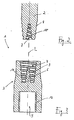
- FIG. 1 shows an embodiment of the socket joint according to the invention for concrete reinforcement rods of materials with mutually different elastic moduli, which is designated as a whole by the reference numeral 1.
- the socket joint 1 is in FIG. 1 shown in the separated state, in which the concrete reinforcing bars, of which in FIG. 1 only one is shown explicitly, not inserted into the actual sleeve part 3.
- the socket joint 1 is particularly suitable for connecting a reinforcing steel bar with a rod 2 made of glass fiber reinforced plastic (GRP), since the materials mentioned have particularly different elastic moduli.
- GRP glass fiber reinforced plastic
- the sleeve part 3 has for this purpose a first recess 4 and a per se optional second recess 5, which at opposite sides Ends of the sleeve part 3 are formed.
- the first recess 4 serves to receive the illustrated concrete reinforcing bar 2, which has the relatively lower modulus of elasticity.
- the second recess 5 serves to receive a second concrete reinforcement bar (not shown), which has the higher modulus of elasticity with respect to the concrete reinforcement bar 2.
- the sleeve part 3 is preferably formed in a material which, in particular with regard to the modulus of elasticity, has comparable properties to the material of the second concrete reinforcement bar, not shown, wherein the said material is preferably a suitable steel.
- the sleeve part 3 and the second reinforcing rod can alternatively also be connected to one another by simple gluing, so that correspondingly no second recess is required.
- the sleeve part 3 in the region of the first recess 4 has a reduced material thickness compared to the rest of the sleeve part 3.
- the sleeve part 3 is formed in said region with a reduced outer diameter decreasing towards the corresponding end of the sleeve part 3.
- the embodiment of the socket joint 1 shown further provides that within the first recess 4 an additional internal structure 6 is formed, which in the present case has an in represents the first recess 4 projecting truncated cone, in particular the sectional view in FIG. 3 can be seen.
- a structure 7 complementary to the internal structure 6 of the sleeve part 3 is designed in the form of a frusto-conical recess, so that said structures 6, 7 cooperate flatly when the concrete reinforcing bar 2 is inserted into the sleeve part 3 ,
- surface interaction means in this case that on the inner structure 6 and the complementary structure 7 an enlarged contact or contact surface between the concrete reinforcement bar 2 and the sleeve part 3 is created, so that despite the relatively short overlap length UL improved material activation for voltage transmission caused, which in turn contributes to slip reduction.
- the inner structure 6 of the sleeve part 3 and the complementary structure 7 of the concrete reinforcing bar 2 are arranged or formed symmetrically to the longitudinal axis L of the sleeve joint 1 shown.
- the concrete reinforcing bar 2 which is preferably formed in said glass fiber reinforced plastic (GRP), has a conically tapered connection end, wherein the first recess 4 of the sleeve part 3 is formed correspondingly complementary.
- This special shape further contributes to an ideally linear load profile in the contact or connection area.
- the concrete reinforcing bar 2 at its connection end, first an external thread 8 and the sleeve part 3 in the region of the first recess 4 has a corresponding internal thread 9.
- the concrete reinforcement rod 2 has in the region of the complementary structure 7 an additional internal thread 10 (cf. FIG. 2 ), while the inner structure 6 of the sleeve part 3 a correspondingly complementary external thread 11 (see. FIG. 3 ) is provided.
- the threads of the concrete reinforcing bar 2 on the one hand and the sleeve part 3 on the other hand can be offset from each other and / or formed differently with respect to their pitches to ensure a secure connection of said components - especially if these by introducing an adhesive, such as synthetic resin, in the first Recess mediated or supported.
- a thread 12 is provided, which may be formed for connection to the concrete reinforcing bar, not shown in a conventional manner.
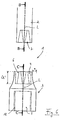
- FIGS. 4 and 5 show the above with reference to the FIGS. 1 to 3 explained in detail embodiment of the socket joint according to the invention in the assembled state and under suggestion of the second concrete reinforcing bar 2 ', with the corresponding figures otherwise not be discussed.
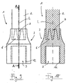
- FIGS. 6 to 10 show a further embodiment of the socket joint 1 according to the invention, in the present case for the sake of brevity only on the essential differences from the above-detailed embodiment according to the FIGS. 1 to 5 will be discussed in more detail.
- the sleeve part 3 and the concrete reinforcing bar 2 are formed with an even shorter overlapping area ÜL '.
- the cross-section or radius decrease a of the sleeve part is also according to FIG. 6 significantly more pronounced than in the FIGS. 1 to 5 ,
- an inner structure 6 is formed in the region of the first exception 4 of the sleeve part 3, which in cross-section (see. FIG. 8 ) is again formed as a truncated cone as a whole, but in addition also has a central, also frusto-conical recess 13, which just vice versa is oriented to the truncated cone-like course of the remaining inner structure 6.
- the structure 7 at the connection end of the concrete reinforcing bar 2 is in turn formed complementary to the above-described inner structure 6 and consists for this purpose of a conical recess (see. FIGS. 1 to 5 ), in which, however, a conical projection 14 which projects in the opposite direction, which is designed to engage in the additional recess 13 of the sleeve part 3, projects centrally.
- the concrete reinforcing rod 2 does not taper at its connection end, and the outer wall 15 of the recess 4 of the sleeve part 3 also extends in a complementary manner parallel to the longitudinal axis L of the socket joint 1.
- FIGS. 9 and 10 show the embodiment of the sleeve joint 1 described above in detail in the assembled state.
- FIGS. 11 to 15 show a further embodiment of the socket joint 1 according to the invention, again in turn only essential differences compared to the embodiments already described will be discussed.
- FIGS. 11 to 15 The in the FIGS. 11 to 15 The embodiment shown essentially corresponds to that according to FIGS. 6 to 10 , where only the projecting Structures in the region of the first recess 4 of the sleeve part 3, which form said inner structure 6, are formed with walls 16, 17 oriented parallel to the longitudinal axis L of the socket joint 1. Overall, this results in the appearance of a hollow circular cylindrical portion for the inner structure 6, while the structure 7 is formed correspondingly complementary at the terminal end of the concrete reinforcing bar 2, as shown in the figures.
- threaded means can be provided, which in the FIGS. 11 to 15 is not explicitly shown.
- the present invention is not limited to the rotationally symmetrical embodiments described above by way of example.
- the inner structure 6 may also be formed in the form of a preferably uniform grid of lamellae, pins or the like, which cooperate with corresponding complementary structures (receptacles) at the attachment end of the concrete reinforcement bar 2 in order to create the largest possible contact surface.
Claims (14)
- Liaison (1) par manchon pour une première barre (2) d'armature à béton et une deuxième barre (2') d'armature à béton, la première barre (2) d'armature à béton et la deuxième barre (2') d'armature à béton étant formées de matériaux ayant des modules d'élasticité différents l'un de l'autre, en particulier pour une barre (2') en acier à béton et une barre (2) en matière plastique renforcée de fibres de verre, liaison selon laquelle les barres (2) d'armature à béton sont respectivement reliées par une extrémité de liaison à un élément (3) formant manchon qui présente au moins un premier évidement (4) pour recevoir la première barre (2) d'armature à béton, laquelle première barre (2) d'armature à béton présente un module d'élasticité relativement inférieur, et élément qui présente un autre point de liaison, en particulier un deuxième évidement (5), pour la deuxième barre (2') d'armature à béton, laquelle deuxième barre (2') d'armature à béton présente un module d'élasticité relativement supérieur,
caractérisée en ce qu'au moins une structure intérieure supplémentaire (6), sous la forme d'un corps géométrique s'enfonçant dans le premier évidement (4) dans la direction d'un axe longitudinal (L) de la liaison (1) par manchon, est configurée à l'intérieur du premier évidement (4), structure qui coopère surfaciquement avec des structures complémentaires (7) à l'extrémité de liaison, insérée dans l'élément (3) formant manchon, de la première barre (2) d'armature à béton. - Liaison (1) par manchon selon la revendication 1, caractérisée en ce que l'élément (3) formant manchon présente, dans la région du premier évidement (4), une épaisseur de matériau réduite, en particulier un diamètre extérieur réduit, par rapport au reste de l'élément (3) formant manchon.
- Liaison (1) par manchon selon la revendication 1 ou 2, caractérisée en ce que l'élément (3) formant manchon, dans la région du premier évidement (4), se rétrécit extérieurement (a) de manière sensiblement tronconique en direction de son extrémité.
- Liaison (1) par manchon selon au moins une des revendications 1 à 3, caractérisée en ce que la structure intérieure (6) est configurée et/ou est disposée symétriquement par rapport à l'axe longitudinal (L) de l'élément (3) formant manchon.
- Liaison (1) par manchon selon au moins une des revendications 1 à 4, caractérisée en ce que la structure intérieure (6) est réalisée à symétrie de révolution par rapport à l'axe longitudinal (L) de l'élément (3) formant manchon.
- Liaison (1) par manchon selon au moins une des revendications 1 à 5, caractérisée en ce que la structure intérieure (6) est réalisée sous la forme d'un tronc de cône s'enfonçant dans le premier évidement (4).
- Liaison (1) par manchon selon au moins une des revendications 1 à 5, caractérisée en ce que la structure intérieure (6) est réalisée sous la forme d'un segment de cylindre circulaire creux s'enfonçant dans le premier évidement (4).
- Liaison (1) par manchon selon au moins une des revendications 1 à 5, caractérisée en ce que la structure intérieure (6) est formée d'un certain nombre de lamelles, de pointes ou analogues.
- Liaison (1) par manchon selon au moins une des revendications 1 à 8, caractérisée en ce que la paroi intérieure (15) du premier évidement (4) est réalisée complémentaire à une paroi opposée (17) de la structure intérieure (6).
- Liaison (1) par manchon selon au moins une des revendications 1 à 9, caractérisée en ce qu'au moins un filetage (8, 10) est prévu à l'extrémité de liaison de la première barre (2) d'armature à béton, et en ce qu'au moins un filetage complémentaire (9, 11) correspondant est prévu dans le premier évidement (4) de l'élément (3) formant manchon et/ou sur la structure intérieure (6).
- Liaison (1) par manchon selon au moins la revendication 10, caractérisée en ce que le filetage (8, 10) et le filetage complémentaire (9, 11) présentent des pas différents et/ou un certain décalage l'un par rapport à l'autre.
- Liaison (1) par manchon selon au moins une des revendications 1 à 11, caractérisée en ce que l'élément (3) formant manchon est réalisé, dans la région du deuxième évidement (5), cylindrique et lisse avec une section extérieure constante.
- Liaison (1) par manchon selon au moins une des revendications 1 à 12, caractérisée en ce que l'élément (3) formant manchon est réalisé en un matériau correspondant sensiblement au matériau de la deuxième barre (2') d'armature à béton, en particulier en acier.
- Liaison (1) par manchon selon au moins une des revendications 1 à 13, caractérisée en ce qu'un produit adhésif est prévu au moins dans la région du premier évidement (4) pour relier la première barre (2) d'armature à béton et l'élément (3) formant manchon.
Applications Claiming Priority (1)
| Application Number | Priority Date | Filing Date | Title |
|---|---|---|---|
| DE200810018325 DE102008018325A1 (de) | 2008-04-11 | 2008-04-11 | Muffenverbindung für Betonbewehrungsstäbe |
Publications (3)
| Publication Number | Publication Date |
|---|---|
| EP2108759A2 EP2108759A2 (fr) | 2009-10-14 |
| EP2108759A3 EP2108759A3 (fr) | 2012-05-09 |
| EP2108759B1 true EP2108759B1 (fr) | 2016-08-10 |
Family
ID=40565009
Family Applications (1)
| Application Number | Title | Priority Date | Filing Date |
|---|---|---|---|
| EP09001737.7A Not-in-force EP2108759B1 (fr) | 2008-04-11 | 2009-02-07 | Liaison de manchons pour tiges d'armature en béton |
Country Status (5)
| Country | Link |
|---|---|
| EP (1) | EP2108759B1 (fr) |
| CA (1) | CA2661119A1 (fr) |
| DE (1) | DE102008018325A1 (fr) |
| DK (1) | DK2108759T3 (fr) |
| PL (1) | PL2108759T3 (fr) |
Families Citing this family (3)
| Publication number | Priority date | Publication date | Assignee | Title |
|---|---|---|---|---|
| CN103671440B (zh) * | 2013-11-22 | 2015-10-28 | 江苏天舜金属材料集团有限公司 | 一种空中多点垂直钢筋连接节点及其施工方法 |
| SI3272958T1 (sl) * | 2016-07-22 | 2020-08-31 | Schoeck Bauteile Gmbh | Gradbeni element za toplotno izolacijo |
| DE102016113558A1 (de) | 2016-07-22 | 2018-01-25 | Schöck Bauteile GmbH | Bauelement zur Wärmedämmung |
Family Cites Families (6)
| Publication number | Priority date | Publication date | Assignee | Title |
|---|---|---|---|---|
| DE4027230C2 (de) * | 1990-08-29 | 1994-02-17 | Wayss & Freytag Ag | Schraubmuffenverbindung |
| AUPO219296A0 (en) * | 1996-09-06 | 1996-10-03 | Alan H. Reid Pty Ltd | Threaded fastener having insertion depth indicator |
| GB2337477A (en) * | 1998-05-22 | 1999-11-24 | Epoxy Powder Coating Company L | Manufacturing a screw connection and apparatus therefore |
| DE20110720U1 (de) | 2001-06-29 | 2001-08-30 | Schoeck Entwicklungsgmbh | Muffenverbindung für Betonstabstähle |
| DE20111793U1 (de) | 2001-07-19 | 2001-09-20 | Schoeck Entwicklungsgmbh | Muffenverbindung für Betonstäbe |
| EP1680559B1 (fr) * | 2003-10-10 | 2009-12-23 | Erico International Corporation | Dispositif comprenant une barre en plastique renforce par des fibres et servant a transmettre une charge a travers une couche calorifuge |
-
2008
- 2008-04-11 DE DE200810018325 patent/DE102008018325A1/de not_active Withdrawn
-
2009
- 2009-02-07 EP EP09001737.7A patent/EP2108759B1/fr not_active Not-in-force
- 2009-02-07 DK DK09001737.7T patent/DK2108759T3/en active
- 2009-02-07 PL PL09001737T patent/PL2108759T3/pl unknown
- 2009-04-01 CA CA 2661119 patent/CA2661119A1/fr not_active Abandoned
Also Published As
| Publication number | Publication date |
|---|---|
| PL2108759T3 (pl) | 2017-02-28 |
| DE102008018325A1 (de) | 2009-10-15 |
| CA2661119A1 (fr) | 2009-10-11 |
| DK2108759T3 (en) | 2016-09-26 |
| EP2108759A3 (fr) | 2012-05-09 |
| EP2108759A2 (fr) | 2009-10-14 |
Similar Documents
| Publication | Publication Date | Title |
|---|---|---|
| DE102010043769B4 (de) | Ankerbaugruppe, insbesondere für den Berg- und Tunnelbau | |
| WO2009052804A1 (fr) | Système de connexion pour tubes à double paroi | |
| DE112015003290B4 (de) | Faserverbundwerkstoff-Verbindungsabschnitt, Langfaser-Faserverbundwerkstoffstruktur, Kraftübertragungsverbund und Herstellverfahren zur Herstellung eines Faserverbundwerkstoff-Verbindungsabschnitts | |
| EP2108759B1 (fr) | Liaison de manchons pour tiges d'armature en béton | |
| CH715485A2 (de) | Transportanker. | |
| EP3309327A1 (fr) | Réservoir de transport | |
| EP1886056B1 (fr) | Raccord de tubes | |
| EP2608745B1 (fr) | Douille d'ancrage | |
| WO2008022630A1 (fr) | Tirant d'ancrage | |
| DE102006035191B4 (de) | Medizinische Vorrichtung | |
| EP3135856B1 (fr) | Raccord à baïonnette destiné à accoupler des extrémités de tubes de forage, tiges de forage ou tiges d'ancrage | |
| EP2295719A2 (fr) | Elément de fixation et procédé destiné à la fabrication d'un élément de fixation | |
| DE102010043765B4 (de) | Ankerbaugruppe sowie Verfahren zur Herstellung einer Ankerbaugruppe | |
| EP0739442B1 (fr) | Dispositif d'ancrage dans la roche, en plastique arme fibres de verre, pouvant etre tendu | |
| EP3775434B1 (fr) | Bras avec une fixation par vis interne pour un support de conduit | |
| EP0697530B1 (fr) | Boulon d'ancrage pour béton ou similaire | |
| DE3141928C2 (de) | Bewehrungsstab für Stahlbeton | |
| DE975291C (de) | Kegelgewindeverbindung, insbesondere fuer unmittelbar aneinander anzuschliessende Tiefbohrgestaenge und -rohre | |
| CH664803A5 (de) | Anordnung zur uebertragung einer kraft und verfahren zur herstellung eines ankerstabes. | |
| DE10160441B4 (de) | Säulenschalung | |
| DE202005008121U1 (de) | Rohrförmiges Element mit Anschlag | |
| EP1389658B1 (fr) | Joint à filet de vis pour barres de transmission de force | |
| DE4424278A1 (de) | Hülse für ein Betonbauteil sowie ein eine derartige Hülse aufweisender Querkraft-Dorn | |
| DE202021101738U1 (de) | Befestigungsstab | |
| EP3546668A1 (fr) | Élément d'ancrage |
Legal Events
| Date | Code | Title | Description |
|---|---|---|---|
| PUAI | Public reference made under article 153(3) epc to a published international application that has entered the european phase |
Free format text: ORIGINAL CODE: 0009012 |
|
| AK | Designated contracting states |
Kind code of ref document: A2 Designated state(s): AT BE BG CH CY CZ DE DK EE ES FI FR GB GR HR HU IE IS IT LI LT LU LV MC MK MT NL NO PL PT RO SE SI SK TR |
|
| AX | Request for extension of the european patent |
Extension state: AL BA RS |
|
| PUAL | Search report despatched |
Free format text: ORIGINAL CODE: 0009013 |
|
| AK | Designated contracting states |
Kind code of ref document: A3 Designated state(s): AT BE BG CH CY CZ DE DK EE ES FI FR GB GR HR HU IE IS IT LI LT LU LV MC MK MT NL NO PL PT RO SE SI SK TR |
|
| AX | Request for extension of the european patent |
Extension state: AL BA RS |
|
| RIC1 | Information provided on ipc code assigned before grant |
Ipc: E04C 5/16 20060101AFI20120403BHEP |
|
| 17P | Request for examination filed |
Effective date: 20121024 |
|
| AKX | Designation fees paid |
Designated state(s): AT BE BG CH CY CZ DE DK EE ES FI FR GB GR HR HU IE IS IT LI LT LU LV MC MK MT NL NO PL PT RO SE SI SK TR |
|
| 17Q | First examination report despatched |
Effective date: 20150603 |
|
| GRAP | Despatch of communication of intention to grant a patent |
Free format text: ORIGINAL CODE: EPIDOSNIGR1 |
|
| INTG | Intention to grant announced |
Effective date: 20160307 |
|
| GRAS | Grant fee paid |
Free format text: ORIGINAL CODE: EPIDOSNIGR3 |
|
| GRAA | (expected) grant |
Free format text: ORIGINAL CODE: 0009210 |
|
| AK | Designated contracting states |
Kind code of ref document: B1 Designated state(s): AT BE BG CH CY CZ DE DK EE ES FI FR GB GR HR HU IE IS IT LI LT LU LV MC MK MT NL NO PL PT RO SE SI SK TR |
|
| REG | Reference to a national code |
Ref country code: GB Ref legal event code: FG4D Free format text: NOT ENGLISH |
|
| REG | Reference to a national code |
Ref country code: CH Ref legal event code: EP Ref country code: AT Ref legal event code: REF Ref document number: 819211 Country of ref document: AT Kind code of ref document: T Effective date: 20160815 |
|
| REG | Reference to a national code |
Ref country code: IE Ref legal event code: FG4D Free format text: LANGUAGE OF EP DOCUMENT: GERMAN |
|
| REG | Reference to a national code |
Ref country code: DE Ref legal event code: R096 Ref document number: 502009012923 Country of ref document: DE |
|
| REG | Reference to a national code |
Ref country code: DK Ref legal event code: T3 Effective date: 20160922 |
|
| REG | Reference to a national code |
Ref country code: NL Ref legal event code: FP |
|
| REG | Reference to a national code |
Ref country code: LT Ref legal event code: MG4D |
|
| PG25 | Lapsed in a contracting state [announced via postgrant information from national office to epo] |
Ref country code: IS Free format text: LAPSE BECAUSE OF FAILURE TO SUBMIT A TRANSLATION OF THE DESCRIPTION OR TO PAY THE FEE WITHIN THE PRESCRIBED TIME-LIMIT Effective date: 20161210 Ref country code: LT Free format text: LAPSE BECAUSE OF FAILURE TO SUBMIT A TRANSLATION OF THE DESCRIPTION OR TO PAY THE FEE WITHIN THE PRESCRIBED TIME-LIMIT Effective date: 20160810 Ref country code: NO Free format text: LAPSE BECAUSE OF FAILURE TO SUBMIT A TRANSLATION OF THE DESCRIPTION OR TO PAY THE FEE WITHIN THE PRESCRIBED TIME-LIMIT Effective date: 20161110 Ref country code: HR Free format text: LAPSE BECAUSE OF FAILURE TO SUBMIT A TRANSLATION OF THE DESCRIPTION OR TO PAY THE FEE WITHIN THE PRESCRIBED TIME-LIMIT Effective date: 20160810 |
|
| PG25 | Lapsed in a contracting state [announced via postgrant information from national office to epo] |
Ref country code: ES Free format text: LAPSE BECAUSE OF FAILURE TO SUBMIT A TRANSLATION OF THE DESCRIPTION OR TO PAY THE FEE WITHIN THE PRESCRIBED TIME-LIMIT Effective date: 20160810 Ref country code: PT Free format text: LAPSE BECAUSE OF FAILURE TO SUBMIT A TRANSLATION OF THE DESCRIPTION OR TO PAY THE FEE WITHIN THE PRESCRIBED TIME-LIMIT Effective date: 20161212 Ref country code: LV Free format text: LAPSE BECAUSE OF FAILURE TO SUBMIT A TRANSLATION OF THE DESCRIPTION OR TO PAY THE FEE WITHIN THE PRESCRIBED TIME-LIMIT Effective date: 20160810 Ref country code: SE Free format text: LAPSE BECAUSE OF FAILURE TO SUBMIT A TRANSLATION OF THE DESCRIPTION OR TO PAY THE FEE WITHIN THE PRESCRIBED TIME-LIMIT Effective date: 20160810 |
|
| PG25 | Lapsed in a contracting state [announced via postgrant information from national office to epo] |
Ref country code: EE Free format text: LAPSE BECAUSE OF FAILURE TO SUBMIT A TRANSLATION OF THE DESCRIPTION OR TO PAY THE FEE WITHIN THE PRESCRIBED TIME-LIMIT Effective date: 20160810 Ref country code: RO Free format text: LAPSE BECAUSE OF FAILURE TO SUBMIT A TRANSLATION OF THE DESCRIPTION OR TO PAY THE FEE WITHIN THE PRESCRIBED TIME-LIMIT Effective date: 20160810 |
|
| REG | Reference to a national code |
Ref country code: DE Ref legal event code: R097 Ref document number: 502009012923 Country of ref document: DE |
|
| PG25 | Lapsed in a contracting state [announced via postgrant information from national office to epo] |
Ref country code: BE Free format text: LAPSE BECAUSE OF NON-PAYMENT OF DUE FEES Effective date: 20170228 Ref country code: SK Free format text: LAPSE BECAUSE OF FAILURE TO SUBMIT A TRANSLATION OF THE DESCRIPTION OR TO PAY THE FEE WITHIN THE PRESCRIBED TIME-LIMIT Effective date: 20160810 Ref country code: BG Free format text: LAPSE BECAUSE OF FAILURE TO SUBMIT A TRANSLATION OF THE DESCRIPTION OR TO PAY THE FEE WITHIN THE PRESCRIBED TIME-LIMIT Effective date: 20161110 |
|
| PGFP | Annual fee paid to national office [announced via postgrant information from national office to epo] |
Ref country code: DK Payment date: 20170222 Year of fee payment: 9 |
|
| PLBE | No opposition filed within time limit |
Free format text: ORIGINAL CODE: 0009261 |
|
| STAA | Information on the status of an ep patent application or granted ep patent |
Free format text: STATUS: NO OPPOSITION FILED WITHIN TIME LIMIT |
|
| 26N | No opposition filed |
Effective date: 20170511 |
|
| PG25 | Lapsed in a contracting state [announced via postgrant information from national office to epo] |
Ref country code: SI Free format text: LAPSE BECAUSE OF FAILURE TO SUBMIT A TRANSLATION OF THE DESCRIPTION OR TO PAY THE FEE WITHIN THE PRESCRIBED TIME-LIMIT Effective date: 20160810 |
|
| PG25 | Lapsed in a contracting state [announced via postgrant information from national office to epo] |
Ref country code: MC Free format text: LAPSE BECAUSE OF FAILURE TO SUBMIT A TRANSLATION OF THE DESCRIPTION OR TO PAY THE FEE WITHIN THE PRESCRIBED TIME-LIMIT Effective date: 20160810 |
|
| REG | Reference to a national code |
Ref country code: CH Ref legal event code: PL |
|
| REG | Reference to a national code |
Ref country code: NL Ref legal event code: MM Effective date: 20170301 |
|
| PG25 | Lapsed in a contracting state [announced via postgrant information from national office to epo] |
Ref country code: LI Free format text: LAPSE BECAUSE OF NON-PAYMENT OF DUE FEES Effective date: 20170228 Ref country code: CZ Free format text: LAPSE BECAUSE OF NON-PAYMENT OF DUE FEES Effective date: 20170207 Ref country code: CH Free format text: LAPSE BECAUSE OF NON-PAYMENT OF DUE FEES Effective date: 20170228 Ref country code: FI Free format text: LAPSE BECAUSE OF NON-PAYMENT OF DUE FEES Effective date: 20170207 |
|
| REG | Reference to a national code |
Ref country code: IE Ref legal event code: MM4A |
|
| PG25 | Lapsed in a contracting state [announced via postgrant information from national office to epo] |
Ref country code: NL Free format text: LAPSE BECAUSE OF NON-PAYMENT OF DUE FEES Effective date: 20170301 |
|
| REG | Reference to a national code |
Ref country code: FR Ref legal event code: ST Effective date: 20171031 |
|
| PG25 | Lapsed in a contracting state [announced via postgrant information from national office to epo] |
Ref country code: LU Free format text: LAPSE BECAUSE OF NON-PAYMENT OF DUE FEES Effective date: 20170207 |
|
| PG25 | Lapsed in a contracting state [announced via postgrant information from national office to epo] |
Ref country code: FR Free format text: LAPSE BECAUSE OF NON-PAYMENT OF DUE FEES Effective date: 20170228 |
|
| REG | Reference to a national code |
Ref country code: BE Ref legal event code: MM Effective date: 20170228 |
|
| PG25 | Lapsed in a contracting state [announced via postgrant information from national office to epo] |
Ref country code: IT Free format text: LAPSE BECAUSE OF NON-PAYMENT OF DUE FEES Effective date: 20170207 Ref country code: IE Free format text: LAPSE BECAUSE OF NON-PAYMENT OF DUE FEES Effective date: 20170207 |
|
| REG | Reference to a national code |
Ref country code: AT Ref legal event code: MM01 Ref document number: 819211 Country of ref document: AT Kind code of ref document: T Effective date: 20170207 |
|
| PG25 | Lapsed in a contracting state [announced via postgrant information from national office to epo] |
Ref country code: AT Free format text: LAPSE BECAUSE OF NON-PAYMENT OF DUE FEES Effective date: 20170207 |
|
| PG25 | Lapsed in a contracting state [announced via postgrant information from national office to epo] |
Ref country code: PL Free format text: LAPSE BECAUSE OF NON-PAYMENT OF DUE FEES Effective date: 20170207 |
|
| REG | Reference to a national code |
Ref country code: DK Ref legal event code: EBP Effective date: 20180228 |
|
| PG25 | Lapsed in a contracting state [announced via postgrant information from national office to epo] |
Ref country code: MT Free format text: LAPSE BECAUSE OF FAILURE TO SUBMIT A TRANSLATION OF THE DESCRIPTION OR TO PAY THE FEE WITHIN THE PRESCRIBED TIME-LIMIT Effective date: 20160810 |
|
| PG25 | Lapsed in a contracting state [announced via postgrant information from national office to epo] |
Ref country code: DK Free format text: LAPSE BECAUSE OF NON-PAYMENT OF DUE FEES Effective date: 20180228 |
|
| PGFP | Annual fee paid to national office [announced via postgrant information from national office to epo] |
Ref country code: GB Payment date: 20190221 Year of fee payment: 11 |
|
| PG25 | Lapsed in a contracting state [announced via postgrant information from national office to epo] |
Ref country code: HU Free format text: LAPSE BECAUSE OF FAILURE TO SUBMIT A TRANSLATION OF THE DESCRIPTION OR TO PAY THE FEE WITHIN THE PRESCRIBED TIME-LIMIT; INVALID AB INITIO Effective date: 20090207 |
|
| PG25 | Lapsed in a contracting state [announced via postgrant information from national office to epo] |
Ref country code: CY Free format text: LAPSE BECAUSE OF NON-PAYMENT OF DUE FEES Effective date: 20160810 |
|
| PG25 | Lapsed in a contracting state [announced via postgrant information from national office to epo] |
Ref country code: MK Free format text: LAPSE BECAUSE OF FAILURE TO SUBMIT A TRANSLATION OF THE DESCRIPTION OR TO PAY THE FEE WITHIN THE PRESCRIBED TIME-LIMIT Effective date: 20160810 |
|
| PG25 | Lapsed in a contracting state [announced via postgrant information from national office to epo] |
Ref country code: TR Free format text: LAPSE BECAUSE OF FAILURE TO SUBMIT A TRANSLATION OF THE DESCRIPTION OR TO PAY THE FEE WITHIN THE PRESCRIBED TIME-LIMIT Effective date: 20160810 |
|
| PG25 | Lapsed in a contracting state [announced via postgrant information from national office to epo] |
Ref country code: GR Free format text: LAPSE BECAUSE OF FAILURE TO SUBMIT A TRANSLATION OF THE DESCRIPTION OR TO PAY THE FEE WITHIN THE PRESCRIBED TIME-LIMIT Effective date: 20160810 |
|
| GBPC | Gb: european patent ceased through non-payment of renewal fee |
Effective date: 20200207 |
|
| PG25 | Lapsed in a contracting state [announced via postgrant information from national office to epo] |
Ref country code: GB Free format text: LAPSE BECAUSE OF NON-PAYMENT OF DUE FEES Effective date: 20200207 |
|
| PGFP | Annual fee paid to national office [announced via postgrant information from national office to epo] |
Ref country code: DE Payment date: 20220125 Year of fee payment: 14 |
|
| P01 | Opt-out of the competence of the unified patent court (upc) registered |
Effective date: 20230513 |
|
| REG | Reference to a national code |
Ref country code: DE Ref legal event code: R119 Ref document number: 502009012923 Country of ref document: DE |
|
| PG25 | Lapsed in a contracting state [announced via postgrant information from national office to epo] |
Ref country code: DE Free format text: LAPSE BECAUSE OF NON-PAYMENT OF DUE FEES Effective date: 20230901 |