EP2108407A1 - Dry chemical system for extinguishing difficult fuel or flammable liquid fires in an industrial tank with a roof creating a space above the liquid - Google Patents
Dry chemical system for extinguishing difficult fuel or flammable liquid fires in an industrial tank with a roof creating a space above the liquid Download PDFInfo
- Publication number
- EP2108407A1 EP2108407A1 EP09165461A EP09165461A EP2108407A1 EP 2108407 A1 EP2108407 A1 EP 2108407A1 EP 09165461 A EP09165461 A EP 09165461A EP 09165461 A EP09165461 A EP 09165461A EP 2108407 A1 EP2108407 A1 EP 2108407A1
- Authority
- EP
- European Patent Office
- Prior art keywords
- dry chemical
- tank
- fuel
- foam
- liquid
- Prior art date
- Legal status (The legal status is an assumption and is not a legal conclusion. Google has not performed a legal analysis and makes no representation as to the accuracy of the status listed.)
- Granted
Links
- 239000007788 liquid Substances 0.000 title claims abstract description 81
- 239000000446 fuel Substances 0.000 title claims abstract description 74
- 239000000126 substance Substances 0.000 title claims description 87
- 239000000843 powder Substances 0.000 claims abstract description 5
- 239000006260 foam Substances 0.000 claims description 77
- 238000007599 discharging Methods 0.000 claims description 24
- 239000012530 fluid Substances 0.000 claims description 9
- 210000004709 eyebrow Anatomy 0.000 claims description 7
- 238000004891 communication Methods 0.000 claims description 5
- 230000000630 rising effect Effects 0.000 claims description 3
- 238000013022 venting Methods 0.000 claims description 2
- 238000000034 method Methods 0.000 description 12
- 239000012141 concentrate Substances 0.000 description 4
- XLYOFNOQVPJJNP-UHFFFAOYSA-N water Substances O XLYOFNOQVPJJNP-UHFFFAOYSA-N 0.000 description 4
- 230000001105 regulatory effect Effects 0.000 description 3
- 241001425718 Vagrans egista Species 0.000 description 2
- 238000003780 insertion Methods 0.000 description 2
- 230000037431 insertion Effects 0.000 description 2
- 238000007689 inspection Methods 0.000 description 2
- 235000001674 Agaricus brunnescens Nutrition 0.000 description 1
- 230000003466 anti-cipated effect Effects 0.000 description 1
- 238000013459 approach Methods 0.000 description 1
- QVGXLLKOCUKJST-UHFFFAOYSA-N atomic oxygen Chemical compound [O] QVGXLLKOCUKJST-UHFFFAOYSA-N 0.000 description 1
- 238000012512 characterization method Methods 0.000 description 1
- 239000002131 composite material Substances 0.000 description 1
- 239000002828 fuel tank Substances 0.000 description 1
- 230000000977 initiatory effect Effects 0.000 description 1
- 238000009434 installation Methods 0.000 description 1
- 238000012423 maintenance Methods 0.000 description 1
- 239000000463 material Substances 0.000 description 1
- 239000000203 mixture Substances 0.000 description 1
- 238000012986 modification Methods 0.000 description 1
- 230000004048 modification Effects 0.000 description 1
- 229910052760 oxygen Inorganic materials 0.000 description 1
- 239000001301 oxygen Substances 0.000 description 1
- 230000000505 pernicious effect Effects 0.000 description 1
- 230000002085 persistent effect Effects 0.000 description 1
- 238000007789 sealing Methods 0.000 description 1
- 238000010561 standard procedure Methods 0.000 description 1
- 239000002699 waste material Substances 0.000 description 1
- 238000003466 welding Methods 0.000 description 1
Images


Classifications
-
- A—HUMAN NECESSITIES
- A62—LIFE-SAVING; FIRE-FIGHTING
- A62C—FIRE-FIGHTING
- A62C3/00—Fire prevention, containment or extinguishing specially adapted for particular objects or places
- A62C3/06—Fire prevention, containment or extinguishing specially adapted for particular objects or places of highly inflammable material, e.g. light metals, petroleum products
- A62C3/065—Fire prevention, containment or extinguishing specially adapted for particular objects or places of highly inflammable material, e.g. light metals, petroleum products for containers filled with inflammable liquids
Definitions
- the instant invention relates to a dry chemical system for extinguishing a difficult fuel or flammable liquid fire in an industrial scale storage tank having a roof creating a space above the liquid, typically a fixed roof on top of the tank.
- a roof creating a space above the liquid, usually a fixed conically- or geodesically-shaped roof welded to the top of the tank.
- Such tanks may have a double roof, including an internal floating roof, called a floater, designed to float on top of the fuel/liquid with seals for sealing against the inside tank wall.
- the fixed cone or geodesic top roof is typically attached by welding.
- a roof system comprised of either a single fixed top portion or of two portions, a fixed top and a floater, creates and defines a space or cavity between either the surface of the fuel/liquid and/or the floater below and the top roof above.
- Vents are typically provided to vent to the atmosphere vapors that collect in the space or cavity between the fuel/liquid (or floater) and a top fixed roof.
- the usual vents are "eyebrow vents", comprising spaced rectangular openings around a top portion of the vertical tank wall, and/or roof vents, comprising spaced openings around the periphery of the top roof.
- Each vent typically has a covering of some type.
- NFPA NFPA has guidelines for the rate of foam application and the duration of a foam attack, adjusted for different type fuels or flammable liquids, different foams and different tanks, in order to achieve extinguishment.
- the instant invention teaches, therefore, an improved system designed to cost effectively extinguish a "difficult fire" in a tank with a fixed roof, or a roof that creates a space between the roof and the liquid.
- the improved system is designed in particular to cost effectively extinguish a fire of a difficult to extinguish fuel or flammable liquid having a high-octane content.
- the invention teaches a staged and timed discharge of dry chemical into the space between the burning fuel/liquid and the roof. The timing of the staging of the discharge of the dry chemical is selected to follow a pertinent period of foam application. Dry chemical is a limited and rationed resource. Discharging the dry chemical too soon might be ineffective and, thus, waste the resource.
- the discharging of the dry chemical can be effected by one of several means or techniques, using portable and/or fixed systems.
- a "fixed system" is equipment put in place prior to a fire, fixed prior to an emergency, in anticipation of emergencies. In contrast, portable systems are brought to the locale of the emergency upon notice.
- Vents provided to vent vapors that collect under a roof can be advantageously used as an entry means to discharge the dry chemical into the space above the fuel/liquid and below the roof. Both portable and fixed systems could utilize such existing vents. Alternately special vents for fixed foam systems can be utilized for a fixed dry chemical system.
- the instant staged dry chemical methodology and apparatus for extinguishing a "fixed roof" (so to speak) tank fire may be implemented in various forms, including using portable apparatus and/or fixed systems.
- Fixed systems and/or special portable apparatus could be less risky for firefighters, and as such would be preferred over a portable embodiment requiring firefighters to climb the tank, walk over the roof and insert dry chemical through an existing or created vent or opportune opening with a hand held nozzle.
- diffuse to extinguish fuel or flammable liquid or "difficult fuel or flammable liquid fires” is used herein to refer to fluid fuels or flammable liquids that are, at least, in substantial part, low-surface tension fuels/liquids and/or high-vapor pressure fuels/liquids and/or octane-boosted fuels/liquids and/or oxygenated fuels/liquids.
- low-surface tension fuels/liquids and/or high-vapor pressure fuels/liquids and/or octane-boosted fuels/liquids and/or oxygenated fuels/liquids The implied comparison in these instances would be recognized by one of skill in the art to be with the historic straight chain fuels or flammable liquids of the mid-20th century.
- a tank may be designed with, and originally exist with, a particular roof system, the initiation of a fire or hazard may have altered or destroyed part or all of the original roof system.
- the characterization of a storage tank may have to be reassessed.
- Original floating roofs, or floating roof portions may have tilted or partially sunk or totally sunk.
- Seals may have been destroyed, in whole or in part.
- Fixed roofs may have been blown awry, or may have been partially dislodged or tilted, or at least their connections, such as a welded connection with a tank wall, may have been partially or totally destroyed.
- the instant invention relates to a tank that, at the time of the fire, still has at least a significant roof portion creating a substantially enclosed space above the fuel/liquid and below the roof. That is, the invention relates to situations where a difficult fuel or flammable liquid is on fire and there is at least a significant roof portion above the fuel/liquid surface, defining a substantially enclosed space or cavity therebetween.
- welds may be blown off from an original fixed roof portion, and hatches and vents may be blown apart, the invention applies if there remains a significant space or cavity between a burning fuel/liquid and a roof portion.
- the fuel/liquid may be burning only where it secures sufficient oxygen, such as at least initially where fuel vapors meet the atmosphere at vents or other open portions.
- the instant invention discloses a system for extinguishing a fire of a difficult to extinguish fuel or flammable liquid in a storage tank having at least a roof portion that creates a substantially enclosed space above a significant portion of the liquid and below the roof, usually a tank fitted with a fixed top roof that remains substantially in place.
- the invention includes creating a foam blanket on the fuel/liquid surface, such as by discharging foam into a cavity above the fuel/liquid.
- a foam blanket should be understood to include foam and/or film.
- a foam blanket Preferably, after covering at least 90% of the liquid surface with a foam blanket and/or after establishing a foam blanket for a significant period of time under the circumstances, such that at least a minimal blanket of foam is created under the circumstances, most preferably after at least two-thirds of a NFPA recommended application rate/duration procedure guideline for the foam attack, then discharging dry chemical into a cavity above the foam blanket and below a roof portion.
- the dry chemical would be discharged during the last ten minutes of a NFPA recommended application rate/duration procedure guideline for a foam attack. Dry chemical would typically be discharged for a period of five to fifteen seconds.
- vapor vents offer fortuitous openings for discharging the dry chemical into the cavity between the fuel/liquid and the roof using portable or fixed dry chemical systems.
- a dry chemical fixed system could be already in place, having conduits and a nozzle ready to be connected to dry chemical sources, such as wheeled units or a dry chemical skid, and having a discharge orifice or nozzle in the cavity.
- Fixed apparatus for extinguishing a difficult fuel or flammable liquid fire in a storage tank having a cavity between the fuel/liquid surface and a roof portion could include at least one dry chemical supply pipe or line rising along a portion of a tank wall and having at least one end opening created in a tank vent, such as through a roof or eyebrow vent, or through a fixed foam system opening into the tank.
- the supply pipe could be placed in fluid communication with a wheeled unit, a skid, or the like, having a source of dry powder.
- the supply pipe is preferably permanently affixed, but could be portable.
- FIG. 1 illustrates tank T having what is referred to as a composite roof system, the system comprised of a floating roof portion or floater FR and a fixed roof portion FXR. Space or cavity C is created between the floating roof portion FR and fixed roof portion FXR.
- Floating roof portion FR is understood to be floating on top of fuel/liquid F in tank T. It should be understood and appreciated that were there no floater, or were no floater to substantially remain at the time of a fire, the space or cavity C would be created above the fuel/liquid surface and below the fixed top roof portion.
- fuel/liquid F is a blended fuel.
- Blended fuels can have a high-octane content that leads to difficult extinguishment situations.
- Fuel/liquid F is at least a difficult fuel/liquid to extinguish.
- Tank T in Figure 1 also illustrates portions of a fixed or portable system for application of dry chemical, comprising a ring-shaped pipe extension PE having pipe extension legs with “T"ed ends PEN.
- Figure 4 is a more detailed figure illustrating a pipe extension PE having "T"ed ends PEN.
- the "T"ed ends are structured to insert into eyebrow vents EV of tank T and to discharge therein a dry chemical, discharged inside of the tank shell into cavity C.
- fixed roof portion FXR is a cone roof fixed to the top of the tank wall. Geodesic-shaped fixed top roofs are also known. Floating roof portion FR floats up and down with the surface of the fuel/liquid left in the tank T and has seals to seal against the inner tank wall.
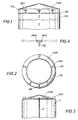
- Figure 2 illustrates a top view of a cone roof FXR having a series of roof vents RV and roof vent covers CRV.
- Figure 2 also illustrates portions of a fixed or portable system for application of dry chemical, including top extension TE extending up and onto cone roof FXR.
- pipe or line extension PE circles cone roof FXR proximate vents RV.
- a portion of pipe or line extension PE extends to vents RV such that the extension is capable of discharging dry chemical through the vent into cavity C in the tank.
- Figure 3 illustrates a portion of a dry chemical (fixed or portable) system including a riser pipe or supply pipe P.
- a riser pipe or supply pipe P Preferably a tank comes equipped with a fixed riser pipe for application of dry chemical.
- a non-fixed portable dry chemical riser pipe P, or line could be utilized.
- the pipe extension and pipe end might be no more than the end part of a straight riser pipe P.
- An end of such a straight dry chemical riser pipe could be inserted or wedged during a fire into an eyebrow vent.
- the methodology can be carried out by firefighters using portable nozzles attached to supply lines. In such cases, however, a firefighter would have to approach (or to create) appropriate vents or openings on the tank or on the roof, proximate a cavity, in order to insert a dry chemical nozzle through the vent or opening.
- the methodology for extinguishing a difficult fire in a tank with a fixed roof portion includes an initial foam attack wherein a foam blanket is created.
- foam includes film.
- foam is inserted into a cavity between a floating bottom roof portion and/or the fuel/liquid surface and a top roof portion to establish and create a foam blanket.
- Foam should be inserted or placed in the cavity until the fuel/liquid surface is substantially covered and the fire is substantially abated.
- Substantial abatement of the fire can be determined to have occurred in most cases when a foam blanket has been laid upon the surface of the fuel/liquid and/or floating roof in accordance with present NFPA guidelines for the foam, fuel/liquid and tank.
- the period of time this takes varies depending upon the type of foam used, the capacity for discharging foam, the size and complexity of the tank and the nature of the fuel/liquid it contains. Forty-five minutes represents a typical regulatorily approved time period for launching and sustaining a foam attack in a cavity between a floating roof and a top roof.
- dry chemical would be inserted through one or more vents, or other available tank openings, into the cavity. If safer or more remotely activatable means are not available, the dry chemical attack can be implemented by a firefighter carrying a hand held nozzle, attached to a line and source of dry chemical, up to a suitable opening into the cavity.
- Dry chemical is a relatively scarce commodity at a fire.
- the usage of dry chemical is carefully marshaled. Limitations on the supply of dry chemical make discharging dry chemical, even for a period of minutes, essentially unfeasible or impossible.
- dry chemical if it is to be utilized, must be utilized judiciously.
- a dry chemical attack is not preferred to be commenced until at least after two-thirds of the time period for a standard recommended NFPA foam attack as per NFPA guidelines.
- the dry chemical attack preferably should not be begun until sometime in approximately the last 20 minutes, preferably not until sometime in the last 10 minutes. If there is no NFPA recommended application rate/duration procedure guideline for a particular foam or tank or fire in a given circumstance, the firefighter should extrapolate a reasonable guideline for the situation based on existing NFPA recommendations in the closest related circumstances, and take that as the NFPA guideline for this case.
- FIG. 5 illustrates a tank T having a fixed roof FXR and a preferred embodiment for a fixed system for use in applying foam and dry chemical.
- the preferred fixed system for use in applying foam and dry chemical includes a foam expansion chamber FC-HC and related conduits and valving attached to a tank, the apparatus modified to provide dry chemical capabilities.
- Chamber FC-HC is shown attached at an upper level of a wall portion of tank T and communicating with the inside of the tank through opening O.
- Foam chamber FC-HC is shown in this embodiment having its own opening O or port into the inside of tank T and cavity C.
- Fixed pipe P communicates dry chemical between a typically mobile or portable dry chemical supply system, which could comprise, for instance, dry chemical wheeled units DCWV or a typical dry chemical skid DCS brought to the emergency. Dry chemical wheeled units would typically feed into a dry chemical collection manifold CM and then through a line to fixed pipe P.
- Fixed pipe P channels the dry chemical through foam expansion chamber FC-HC and through opening O to a discharge orific
- Figures 6 and 7 offer a side view and a plan view of foam expansion chamber FC-HC with dry chemical capabilities, as well as related conduits and valving.
- the foam expansion chamber provides a chamber for expansion and loss of velocity of the foam concentrate, prior to being discharged through opening O in sidewall of tank T.
- the foam system is fed fire extinguishing fluid comprising liquid water and foam concentrate through fluid pipe FP.
- the water and foam concentrate liquid passes through orifice plate OP having a small hole or orifice, creating a pressure differential there through.
- Orifice plate OP has a handle H and resembles a paddle. Pressure differential created over the orifice plate in line FP serves to draw in air through air vent AV shown as a mushroom vent with a screen.
- a check valve V is presented in the line as a vapor seal. Sufficient pressure from the water, foam concentrate and air will break the vapor seal sending the fluid into foam chamber FC. In foam chamber FC the foam will further expand and lose velocity prior to being discharged through opening O into the inside of tank T. Foam chamber FC is shown with an inspection cover or hatch CV, particularly important for inspection of the vapor seals.
- a chemical is fed from a source through pipe P, through its own check valve, vapor seal V, and then extending through opening O to a dry chemical discharge tip.
- the vapor seals or check valves may be of different designs and locations.
- Figures 6 and 7 also illustrate a high flow discharge tip HFT and a low flow discharge tip LFT.
- the discharge tip provides for discharging dry chemical preferably in three directions, to the left, to the right and adjustably toward the center.
- the tip might discharge in just one direction, preferably then adjustably toward the center.
- the discharge tip is preferably adjustable upon installation for anticipated preferred flow rates and directions, given the tank size. For instance, the discharge tip might be adjusted to discharge approximately 70 pounds per second total, 30 pounds per second to the left, 30 pounds per second to the right and 10 pounds per second toward a central area.
Abstract
Description
- The instant invention relates to a dry chemical system for extinguishing a difficult fuel or flammable liquid fire in an industrial scale storage tank having a roof creating a space above the liquid, typically a fixed roof on top of the tank.
- Industrial fuel and/or flammable liquid storage tanks frequently have a roof creating a space above the liquid, usually a fixed conically- or geodesically-shaped roof welded to the top of the tank. Such tanks may have a double roof, including an internal floating roof, called a floater, designed to float on top of the fuel/liquid with seals for sealing against the inside tank wall. The fixed cone or geodesic top roof is typically attached by welding. A roof system comprised of either a single fixed top portion or of two portions, a fixed top and a floater, creates and defines a space or cavity between either the surface of the fuel/liquid and/or the floater below and the top roof above.
- Vents are typically provided to vent to the atmosphere vapors that collect in the space or cavity between the fuel/liquid (or floater) and a top fixed roof. The usual vents are "eyebrow vents", comprising spaced rectangular openings around a top portion of the vertical tank wall, and/or roof vents, comprising spaced openings around the periphery of the top roof. Each vent typically has a covering of some type.
- In the event of a fire in the fuel or flammable liquid tank having a fixed top roof, it is industry standard procedure, regulated by the NFPA, to extinguish the fire (or at least to attempt to do so) by a foam attack, the attack comprising laying a foam blanket on the fuel/liquid surface, typically by discharging foam into the space or cavity between and a fixed top roof and the liquid surface and/or a floater. It should be understood that the fire may, at least initially, occur only at the vents, where the fuel/liquid vapors meet atmospheric air. The vapor mixture in the cavity, at least initially, may be too rich to burn. NFPA has guidelines for the rate of foam application and the duration of a foam attack, adjusted for different type fuels or flammable liquids, different foams and different tanks, in order to achieve extinguishment.
- Recent discoveries by the instant inventor while extinguishing a blended fuel tank fire in Guatemala, revealed that foam alone may not extinguish a difficult fuel or flammable liquid fire in a storage tank having a fixed top roof, even when foam is placed in the cavity in accordance with NFPA recommended procedures, rates and durations. This appears disturbingly true of the new blended fuels having a high-octane content. It is a disconcerting discovery. Foam alone may not extinguish the fire at all, and quite likely will not do so per current NFPA regulations or guidelines.
- The instant invention teaches, therefore, an improved system designed to cost effectively extinguish a "difficult fire" in a tank with a fixed roof, or a roof that creates a space between the roof and the liquid. The improved system is designed in particular to cost effectively extinguish a fire of a difficult to extinguish fuel or flammable liquid having a high-octane content. The invention teaches a staged and timed discharge of dry chemical into the space between the burning fuel/liquid and the roof. The timing of the staging of the discharge of the dry chemical is selected to follow a pertinent period of foam application. Dry chemical is a limited and rationed resource. Discharging the dry chemical too soon might be ineffective and, thus, waste the resource.
- The discharging of the dry chemical can be effected by one of several means or techniques, using portable and/or fixed systems. (A "fixed system" is equipment put in place prior to a fire, fixed prior to an emergency, in anticipation of emergencies. In contrast, portable systems are brought to the locale of the emergency upon notice.) Vents provided to vent vapors that collect under a roof can be advantageously used as an entry means to discharge the dry chemical into the space above the fuel/liquid and below the roof. Both portable and fixed systems could utilize such existing vents. Alternately special vents for fixed foam systems can be utilized for a fixed dry chemical system.
- It is the inventor's experience and observation that dry chemicals, timely inserted into the space between burning fuel/liquid and the roof, after substantial foam attack, chase any remaining persistent, pernicious fire or vagrant flames in the cavity and serve to completely extinguish the fire. Foam alone is an inferior more costly means, if not a totally inadequate means, to completely extinguish residual flames in such a tank. Foam is expensive. The extra time required to secure extinguishment, even if it can be achieved, with a continued application of foam alone as compared to the instant invention, is unnecessarily costly.
- The instant staged dry chemical methodology and apparatus for extinguishing a "fixed roof" (so to speak) tank fire may be implemented in various forms, including using portable apparatus and/or fixed systems. Fixed systems and/or special portable apparatus could be less risky for firefighters, and as such would be preferred over a portable embodiment requiring firefighters to climb the tank, walk over the roof and insert dry chemical through an existing or created vent or opportune opening with a hand held nozzle.
- The term "difficult to extinguish fuel or flammable liquid" or "difficult fuel or flammable liquid fires" is used herein to refer to fluid fuels or flammable liquids that are, at least, in substantial part, low-surface tension fuels/liquids and/or high-vapor pressure fuels/liquids and/or octane-boosted fuels/liquids and/or oxygenated fuels/liquids. The implied comparison in these instances would be recognized by one of skill in the art to be with the historic straight chain fuels or flammable liquids of the mid-20th century.
- It should be understood that although a tank may be designed with, and originally exist with, a particular roof system, the initiation of a fire or hazard may have altered or destroyed part or all of the original roof system. Thus, the characterization of a storage tank may have to be reassessed. Original floating roofs, or floating roof portions, may have tilted or partially sunk or totally sunk. Seals may have been destroyed, in whole or in part. Fixed roofs may have been blown awry, or may have been partially dislodged or tilted, or at least their connections, such as a welded connection with a tank wall, may have been partially or totally destroyed. The instant invention relates to a tank that, at the time of the fire, still has at least a significant roof portion creating a substantially enclosed space above the fuel/liquid and below the roof. That is, the invention relates to situations where a difficult fuel or flammable liquid is on fire and there is at least a significant roof portion above the fuel/liquid surface, defining a substantially enclosed space or cavity therebetween. Although welds may be blown off from an original fixed roof portion, and hatches and vents may be blown apart, the invention applies if there remains a significant space or cavity between a burning fuel/liquid and a roof portion. Note again: the fuel/liquid may be burning only where it secures sufficient oxygen, such as at least initially where fuel vapors meet the atmosphere at vents or other open portions.
- The instant invention discloses a system for extinguishing a fire of a difficult to extinguish fuel or flammable liquid in a storage tank having at least a roof portion that creates a substantially enclosed space above a significant portion of the liquid and below the roof, usually a tank fitted with a fixed top roof that remains substantially in place. The invention includes creating a foam blanket on the fuel/liquid surface, such as by discharging foam into a cavity above the fuel/liquid. (A foam blanket should be understood to include foam and/or film.) Preferably, after covering at least 90% of the liquid surface with a foam blanket and/or after establishing a foam blanket for a significant period of time under the circumstances, such that at least a minimal blanket of foam is created under the circumstances, most preferably after at least two-thirds of a NFPA recommended application rate/duration procedure guideline for the foam attack, then discharging dry chemical into a cavity above the foam blanket and below a roof portion. Preferably the dry chemical would be discharged during the last ten minutes of a NFPA recommended application rate/duration procedure guideline for a foam attack. Dry chemical would typically be discharged for a period of five to fifteen seconds. Existing vapor vents offer fortuitous openings for discharging the dry chemical into the cavity between the fuel/liquid and the roof using portable or fixed dry chemical systems. Preferably a dry chemical fixed system could be already in place, having conduits and a nozzle ready to be connected to dry chemical sources, such as wheeled units or a dry chemical skid, and having a discharge orifice or nozzle in the cavity.
- Fixed apparatus for extinguishing a difficult fuel or flammable liquid fire in a storage tank having a cavity between the fuel/liquid surface and a roof portion could include at least one dry chemical supply pipe or line rising along a portion of a tank wall and having at least one end opening created in a tank vent, such as through a roof or eyebrow vent, or through a fixed foam system opening into the tank. The supply pipe could be placed in fluid communication with a wheeled unit, a skid, or the like, having a source of dry powder. The supply pipe is preferably permanently affixed, but could be portable.
- A better understanding of the present invention can be obtained when the following detailed description of the preferred embodiments are considered in conjunction with the following drawings, in which:
-
Figure 1 illustrates a tank with a fixed top roof and a floater, creating a space or cavity in between. It should be understood that if a floater were not there, the space or cavity would be between the liquid surface and the fixed top. -
Figure 2 illustrates a top view of a fixed top roof on a tank. The roof illustrates vents and portions of a dry chemical supply system. -
Figure 3 illustrates a dry chemical riser pipe for a tank with a fixed roof. -
Figure 4 illustrates an embodiment of a dry chemical discharge head for insertion inside a tank shell, preferably for insertion inside a vent. -
Figure 5 illustrates a tank with a fixed roof, the tank having a fixed foam system and a fixed dry chemical system. -
Figures 6 and 7 illustrate details of the fixed foam and dry chemical system ofFigure 5 . - The drawings are primarily illustrative. It would be understood that structure may have been simplified and details omitted in order to convey certain aspects of the invention. Scale may be sacrificed to clarity.
-
Figure 1 illustrates tank T having what is referred to as a composite roof system, the system comprised of a floating roof portion or floater FR and a fixed roof portion FXR. Space or cavity C is created between the floating roof portion FR and fixed roof portion FXR. Floating roof portion FR is understood to be floating on top of fuel/liquid F in tank T. It should be understood and appreciated that were there no floater, or were no floater to substantially remain at the time of a fire, the space or cavity C would be created above the fuel/liquid surface and below the fixed top roof portion. - In a worst-case scenario, fuel/liquid F is a blended fuel. Blended fuels can have a high-octane content that leads to difficult extinguishment situations. Fuel/liquid F is at least a difficult fuel/liquid to extinguish.
- Tank T in
Figure 1 also illustrates portions of a fixed or portable system for application of dry chemical, comprising a ring-shaped pipe extension PE having pipe extension legs with "T"ed ends PEN.Figure 4 is a more detailed figure illustrating a pipe extension PE having "T"ed ends PEN. The "T"ed ends are structured to insert into eyebrow vents EV of tank T and to discharge therein a dry chemical, discharged inside of the tank shell into cavity C. - In a typical embodiment fixed roof portion FXR is a cone roof fixed to the top of the tank wall. Geodesic-shaped fixed top roofs are also known. Floating roof portion FR floats up and down with the surface of the fuel/liquid left in the tank T and has seals to seal against the inner tank wall.
-
Figure 2 illustrates a top view of a cone roof FXR having a series of roof vents RV and roof vent covers CRV.Figure 2 also illustrates portions of a fixed or portable system for application of dry chemical, including top extension TE extending up and onto cone roof FXR. In the embodiment ofFigure 2 pipe or line extension PE circles cone roof FXR proximate vents RV. A portion of pipe or line extension PE extends to vents RV such that the extension is capable of discharging dry chemical through the vent into cavity C in the tank. -
Figure 3 illustrates a portion of a dry chemical (fixed or portable) system including a riser pipe or supply pipe P. Preferably a tank comes equipped with a fixed riser pipe for application of dry chemical. However, a non-fixed portable dry chemical riser pipe P, or line, could be utilized. In a simple case, the pipe extension and pipe end might be no more than the end part of a straight riser pipe P. An end of such a straight dry chemical riser pipe could be inserted or wedged during a fire into an eyebrow vent. - In a situation where no fixed application system for dry chemical exists, offering preinstalled elements such as riser pipes, or pipe extensions, pipe ends and/or nozzles, the methodology can be carried out by firefighters using portable nozzles attached to supply lines. In such cases, however, a firefighter would have to approach (or to create) appropriate vents or openings on the tank or on the roof, proximate a cavity, in order to insert a dry chemical nozzle through the vent or opening.
- The methodology for extinguishing a difficult fire in a tank with a fixed roof portion includes an initial foam attack wherein a foam blanket is created. (Again, foam includes film.) Preferably foam is inserted into a cavity between a floating bottom roof portion and/or the fuel/liquid surface and a top roof portion to establish and create a foam blanket. Foam should be inserted or placed in the cavity until the fuel/liquid surface is substantially covered and the fire is substantially abated. Substantial abatement of the fire can be determined to have occurred in most cases when a foam blanket has been laid upon the surface of the fuel/liquid and/or floating roof in accordance with present NFPA guidelines for the foam, fuel/liquid and tank. The period of time this takes varies depending upon the type of foam used, the capacity for discharging foam, the size and complexity of the tank and the nature of the fuel/liquid it contains. Forty-five minutes represents a typical regulatorily approved time period for launching and sustaining a foam attack in a cavity between a floating roof and a top roof. In a preferred embodiment, sometime during the last ten minutes of any such foam attack, dry chemical would be inserted through one or more vents, or other available tank openings, into the cavity. If safer or more remotely activatable means are not available, the dry chemical attack can be implemented by a firefighter carrying a hand held nozzle, attached to a line and source of dry chemical, up to a suitable opening into the cavity. A ten second application of dry chemical offers a reasonable expectation for extinguishing the remnants of the fire, the vagrant remaining flames associated with the difficult fire, especially those associated with the new blended fuels. It is the experience of the instant inventor that dry chemical timely inserted into such cavities in the above situation appears to "chase" the remaining fire within the cavity and to extinguish it. Without such dry chemical treatment, for difficult fuels maintenance of a foam blanket may have to be extended for two or three times the present regulatorily set time periods, incurring considerable unanticipated expense. Indeed, there is no guarantee or experience conclusively showing that foam alone can extinguish a fire of a difficult flammable liquid in a tank under a fixed roof.
- Dry chemical is a relatively scarce commodity at a fire. The usage of dry chemical is carefully marshaled. Limitations on the supply of dry chemical make discharging dry chemical, even for a period of minutes, essentially unfeasible or impossible. Hence, dry chemical, if it is to be utilized, must be utilized judiciously. As a resource, compared to water and/or foam, in almost all circumstances its availability for use must be considered to be quite limited. Thus, a dry chemical attack is not preferred to be commenced until at least after two-thirds of the time period for a standard recommended NFPA foam attack as per NFPA guidelines. For example, if the foam attack should last over 55 to 60 minutes, the dry chemical attack preferably should not be begun until sometime in approximately the last 20 minutes, preferably not until sometime in the last 10 minutes. If there is no NFPA recommended application rate/duration procedure guideline for a particular foam or tank or fire in a given circumstance, the firefighter should extrapolate a reasonable guideline for the situation based on existing NFPA recommendations in the closest related circumstances, and take that as the NFPA guideline for this case.
-
Figure 5 illustrates a tank T having a fixed roof FXR and a preferred embodiment for a fixed system for use in applying foam and dry chemical. The preferred fixed system for use in applying foam and dry chemical includes a foam expansion chamber FC-HC and related conduits and valving attached to a tank, the apparatus modified to provide dry chemical capabilities. Chamber FC-HC is shown attached at an upper level of a wall portion of tank T and communicating with the inside of the tank through opening O. Foam chamber FC-HC is shown in this embodiment having its own opening O or port into the inside of tank T and cavity C. Fixed pipe P communicates dry chemical between a typically mobile or portable dry chemical supply system, which could comprise, for instance, dry chemical wheeled units DCWV or a typical dry chemical skid DCS brought to the emergency. Dry chemical wheeled units would typically feed into a dry chemical collection manifold CM and then through a line to fixed pipe P. Fixed pipe P channels the dry chemical through foam expansion chamber FC-HC and through opening O to a discharge orifice or nozzle inside the tank. -
Figures 6 and 7 offer a side view and a plan view of foam expansion chamber FC-HC with dry chemical capabilities, as well as related conduits and valving. The foam expansion chamber provides a chamber for expansion and loss of velocity of the foam concentrate, prior to being discharged through opening O in sidewall of tank T. The foam system is fed fire extinguishing fluid comprising liquid water and foam concentrate through fluid pipe FP. The water and foam concentrate liquid passes through orifice plate OP having a small hole or orifice, creating a pressure differential there through. Orifice plate OP has a handle H and resembles a paddle. Pressure differential created over the orifice plate in line FP serves to draw in air through air vent AV shown as a mushroom vent with a screen. In the instant embodiment a check valve V is presented in the line as a vapor seal. Sufficient pressure from the water, foam concentrate and air will break the vapor seal sending the fluid into foam chamber FC. In foam chamber FC the foam will further expand and lose velocity prior to being discharged through opening O into the inside of tank T. Foam chamber FC is shown with an inspection cover or hatch CV, particularly important for inspection of the vapor seals. - In regard to the associated fixed system for the application of dry chemical, a chemical is fed from a source through pipe P, through its own check valve, vapor seal V, and then extending through opening O to a dry chemical discharge tip. The vapor seals or check valves may be of different designs and locations.
Figures 6 and 7 also illustrate a high flow discharge tip HFT and a low flow discharge tip LFT. The discharge tip provides for discharging dry chemical preferably in three directions, to the left, to the right and adjustably toward the center. The tip might discharge in just one direction, preferably then adjustably toward the center. The discharge tip is preferably adjustable upon installation for anticipated preferred flow rates and directions, given the tank size. For instance, the discharge tip might be adjusted to discharge approximately 70 pounds per second total, 30 pounds per second to the left, 30 pounds per second to the right and 10 pounds per second toward a central area. - The foregoing description of preferred embodiments of the invention is presented for purposes of illustration and description, and is not intended to be exhaustive or to limit the invention to the precise form or embodiment disclosed. The description was selected to best explain the principles of the invention and their practical application to enable others skilled in the art to best utilize the invention in various embodiments. Various modifications as are best suited to the particular use are contemplated. It is intended that the scope of the invention is not to be limited by the specification, but to be defined by the claims set forth below. Since the foregoing disclosure and description of the invention are illustrative and explanatory thereof, various changes in the size, shape, and materials, as well as in the details of the illustrated device may be made without departing from the spirit of the invention. The invention is claimed using terminology that depends upon a historic presumption that recitation of a single element covers one or more, and recitation of two elements covers two or more, and the like. Also, the drawings and illustration herein have not necessarily been produced to scale.
- Preferred embodiments of the present invention are discussed below, and are referred to as embodiment E1 to embodiment E24.
- E1. A system for treating a flammable liquid fire associated with a tank having a roof and a substantially enclosed space above liquid in the tank and below the roof, comprising:
- establishing a foam/film blanket over at least 90% of a surface of the liquid within the tank; and
- discharging dry powder into a space between the roof and said blanket.
- E2. The method of E1 wherein the discharging step is subsequent to establishing at least two-thirds of an NFPA regulated foam/film blanket.
- E3. The method of E1 wherein the discharging occurs during the last 10 minutes of an NFPA regulated time of application of foam.
- E4. An industrial scale tank with a roof having a substantially enclosed space above a flammable liquid in the tank and below the roof, comprising:
- at least one opening communicating with the space;
- means associated with the tank for creating a foam/film blanket on the liquid; and
- means associated with the at least one opening for discharging dry chemical into the space.
- E5. A fixed foam/dry chemical system for an industrial size tank with a roof having a space above a flammable liquid in the tank and below the roof, comprising:
- at least one foam conduit fixed to the tank, in valved fluid communication with an interior of the tank; and
- at least one dry chemical conduit fixed to the tank, structured for attachment to a source of dry chemical and in valved fluid communication with the space under the roof of the tank.
- E6. The apparatus of E5 including at least three said foam conduits spaced around the tank and at least three said dry chemical conduits spaced around the tank and structured such that at least one foam chamber and one dry chemical conduit communicate with the interior of the tank through one opening in a tank wall.
- E7. The apparatus of E5 including a nozzle for discharge of dry chemical attached to the dry chemical conduit.
- E8. A system for extinguishing a fire of a difficult to extinguish fuel or flammable liquid in a storage tank fitted with at least a significant fixed top roof portion, comprising:
- discharging foam into a cavity above the fuel/liquid and below the fixed top roof portion; and
- after at least two-thirds of the way through a NFPA-recommended application rate/duration procedure guideline for the foam attack, discharging dry chemical into a cavity above the fuel/liquid and below the fixed roof portion.
- E9. The system of E8 that includes discharging dry chemical in the last ten minutes of the NFPA recommended application rate/duration procedure guideline.
- E10. The system of E8 that includes discharging dry chemical for 5 to 15 seconds.
- E11. The system of E8 that includes discharging dry chemical after at least 40 minutes of foam application.
- E12. The system of E8 that includes discharging dry chemical through at least one tank vent.
- E13. The system of E12 wherein the vent is an eyebrow vent.
- E14. The system of E12 wherein the vent is a tank roof vent.
- E15. The system of E8 that includes a floater on top of the fuel/liquid and the discharging of foam and of dry chemical is a discharging into a cavity defined between the floater and the fixed top roof portion.
- E16. The system of E8 wherein the fuel or flammable liquid comprises a blended fuel.
- E17. Apparatus for extinguishing a difficult to extinguish fuel or flammable liquid fire in a storage tank with a fixed roof portion and at least one vent opening into a space defined above the fuel/liquid surface and a fixed roof portion, comprising;
- a storage tank containing a difficult to extinguish fuel or flammable liquid and having a fixed roof portion defining a space or cavity above the fuel/liquid surface and below the fixed roof portion; and
- a dry chemical supply pipe system rising along a portion of the tank wall having at least one end opening into a tank vent venting the space or cavity, the pipe system in fluid communication with a source of dry powder.
- E18. The apparatus of E17 wherein the supply pipe system has multiple ends inserted into multiple tank vents.
- E19. The apparatus of E17 wherein the vent comprises a wall eyebrow vent.
- E20. The apparatus of E17 wherein the vent comprises a roof vent.
- E21. The apparatus of E17 wherein the supply pipe system is permanently affixed to the tank.
- E22. The apparatus of E17 wherein the supply pipe system is portable.
- E23. The apparatus of E17 that includes a floater, and wherein the space defined above the fuel/liquid surface is space defined above the floater.
- E24. The apparatus of E17 wherein the difficult to extinguish fuel or flammable liquid comprises a blended fuel.
Claims (10)
- Apparatus for extinguishing a difficult to extinguish fuel or flammable liquid fire in a storage tank with a fixed roof portion and at least one vent opening into a space defined above the fuel/liquid surface and below a fixed roof portion, comprising;
a storage tank containing a difficult to extinguish fuel or fuel or flammable liquid and having a fixed roof portion defining a space or cavity above the fuel/liquid surface and below the fixed roof portion;
a dry chemical supply pipe system rising along a portion of the tank wall having at least one end opening into a tank vent venting the space or cavity, the pipe system in fluid communication with a source of dry powder; and
wherein the dry chemical supply pipe system end includes a pair of tips discharging to the left and to the right of the tank aperture. - The apparatus of claim 1 wherein the dry chemical supply pipe system is fixed.
- The apparatus of claims 1 or 2 wherein the dry chemical supply pipe system end includes a low flow and a high flow dry chemical discharge tip, the high flow dry chemical discharge tip comprising a pair of tips discharging to the left and to the right aperture.
- The apparatus of any one of claims 1 through 3 wherein the supply pipe system has multiple ends inserted into multiple tank vents.
- The apparatus of any one of claims 1 through 4 wherein the vent comprises a wall eyebrow vent.
- The apparatus of any one of claims 1 through 5 wherein the vent comprises a roof vent.
- The apparatus of claim 3 wherein the low flow dry chemical discharge tip discharges approximately toward the middle of the interior tank.
- The apparatus of any one of claims 1 through 7 wherein the dry chemical supply pipe system is integrated into a fixed foam system and the fixed foam system is structured to discharge foam through the tank aperture.
- The apparatus of any one of claims 1 through 8 that includes a floater, and wherein the space defined above the fuel/liquid surface is space defined above the floater.
- The apparatus of any one of claims 1 through 9 wherein the difficult to extinguish fuel or flammable liquid comprises a blended fuel.
Priority Applications (1)
| Application Number | Priority Date | Filing Date | Title |
|---|---|---|---|
| PL09165461T PL2108407T3 (en) | 2003-08-20 | 2004-08-19 | Dry chemical system for extinguishing difficult fuel or flammable liquid fires in an industrial tank with a roof creating a space above the liquid |
Applications Claiming Priority (3)
| Application Number | Priority Date | Filing Date | Title |
|---|---|---|---|
| US49649403P | 2003-08-20 | 2003-08-20 | |
| US53802104P | 2004-01-21 | 2004-01-21 | |
| EP04781456A EP1660816B1 (en) | 2003-08-20 | 2004-08-19 | Dry chemical system for extinguishing difficult fuel or flammable liquid fires in an industrial tank with a roof creating a space above the liquid |
Related Parent Applications (2)
| Application Number | Title | Priority Date | Filing Date |
|---|---|---|---|
| EP04781456A Division EP1660816B1 (en) | 2003-08-20 | 2004-08-19 | Dry chemical system for extinguishing difficult fuel or flammable liquid fires in an industrial tank with a roof creating a space above the liquid |
| EP04781456.1 Division | 2004-08-19 |
Publications (2)
| Publication Number | Publication Date |
|---|---|
| EP2108407A1 true EP2108407A1 (en) | 2009-10-14 |
| EP2108407B1 EP2108407B1 (en) | 2010-10-06 |
Family
ID=34221410
Family Applications (2)
| Application Number | Title | Priority Date | Filing Date |
|---|---|---|---|
| EP09165461A Active EP2108407B1 (en) | 2003-08-20 | 2004-08-19 | Dry chemical system for extinguishing difficult fuel or flammable liquid fires in an industrial tank with a roof creating a space above the liquid |
| EP04781456A Active EP1660816B1 (en) | 2003-08-20 | 2004-08-19 | Dry chemical system for extinguishing difficult fuel or flammable liquid fires in an industrial tank with a roof creating a space above the liquid |
Family Applications After (1)
| Application Number | Title | Priority Date | Filing Date |
|---|---|---|---|
| EP04781456A Active EP1660816B1 (en) | 2003-08-20 | 2004-08-19 | Dry chemical system for extinguishing difficult fuel or flammable liquid fires in an industrial tank with a roof creating a space above the liquid |
Country Status (8)
| Country | Link |
|---|---|
| US (1) | US20070119605A1 (en) |
| EP (2) | EP2108407B1 (en) |
| AT (2) | ATE462111T1 (en) |
| DE (2) | DE602004029522D1 (en) |
| ES (2) | ES2341961T3 (en) |
| MX (1) | MXPA06001979A (en) |
| PL (2) | PL2108407T3 (en) |
| WO (1) | WO2005019729A2 (en) |
Cited By (1)
| Publication number | Priority date | Publication date | Assignee | Title |
|---|---|---|---|---|
| CN105727475A (en) * | 2016-02-25 | 2016-07-06 | 安徽建筑大学 | Annular foam fire extinguishing system of oil storage tank |
Families Citing this family (14)
| Publication number | Priority date | Publication date | Assignee | Title |
|---|---|---|---|---|
| JP5229939B2 (en) * | 2004-08-19 | 2013-07-03 | ウィルファイア エイチシー、エルエルシー | An improved method for extinguishing flammable liquid fires in industrial storage tanks. |
| US7854288B2 (en) * | 2007-01-10 | 2010-12-21 | Ford Global Technologies, Llc | Automotive fuel storage system with in-tank fuel binder system |
| US7896121B2 (en) * | 2007-01-10 | 2011-03-01 | Ford Global Technologies | Automotive fuel storage system with in-tank fuel encapsulation system |
| JP4792484B2 (en) * | 2008-05-28 | 2011-10-12 | 深田工業株式会社 | Oil tank foam fire extinguishing equipment |
| US20100116513A1 (en) * | 2008-11-13 | 2010-05-13 | Charles Allen Phillips | Storage tank fire suppression system |
| WO2012054073A1 (en) * | 2010-10-19 | 2012-04-26 | Williams Fire & Hazard Control, Inc. | Fixed systems and methods for extinguishing industrial tank fires, with and without fixed roof, including aerated foam projecting nozzles and center directed nozzles |
| RU2470686C1 (en) * | 2011-09-29 | 2012-12-27 | Вячеслав Викторович Кокорин | Device for extinguishing flammable liquids in vertical tank with floating roof or pontoon |
| US9027661B2 (en) * | 2011-12-28 | 2015-05-12 | Kenneth C. Baker | Foam chamber having a closable testing outlet |
| US9151235B2 (en) | 2012-09-20 | 2015-10-06 | Ford Global Technologies, Llc | Method and system for fuel vapor control |
| US20140262361A1 (en) * | 2013-03-13 | 2014-09-18 | Integrated Protection Services, Inc. | Apparatus and method for installing fire suppression foam dispersal device |
| HU231088B1 (en) * | 2014-05-27 | 2020-07-28 | Regional Energy and Environment Est. | Installed foam firefighting equipment for containers containing liquid flammable materials |
| RU170678U1 (en) * | 2016-04-15 | 2017-05-03 | Федеральное государственное автономное образовательное учреждение высшего образования "Сибирский федеральный университет" | FIRE RESISTANCE EQUIPMENT FOR OIL PRODUCT RESERVOIR |
| RU2631170C1 (en) * | 2016-10-31 | 2017-09-19 | Федеральное государственное бюджетное образовательное учреждение высшего образования "Уфимский государственный нефтяной технический университет" | Universal fire installation of combined method of fire extinguishing fire of oil products and oil and gas sector installations |
| CN106829244B (en) * | 2017-03-27 | 2018-04-03 | 孙强丹 | External floating top tank based on dome circulates lazy envelope system and QHSE conveying methods |
Citations (4)
| Publication number | Priority date | Publication date | Assignee | Title |
|---|---|---|---|---|
| US1844373A (en) * | 1926-01-07 | 1932-02-09 | Urquhart Radcliffe Morris | Fire fighting system |
| US2260733A (en) * | 1939-08-29 | 1941-10-28 | Standard Oil Co California | Apparatus for extinguishing oil fires |
| US2692649A (en) | 1951-03-03 | 1954-10-26 | Union Oil Co | Apparatus for extinguishing fires |
| US5573068A (en) * | 1994-06-14 | 1996-11-12 | Council Of Scientific & Industrial Research | Apparatus for extinguishing fires in oil storage tanks |
Family Cites Families (24)
| Publication number | Priority date | Publication date | Assignee | Title |
|---|---|---|---|---|
| US1775846A (en) * | 1924-06-07 | 1930-09-16 | Sadie H Blaw | Fire apparatus |
| US1714015A (en) * | 1927-07-23 | 1929-05-21 | Cons Steel Corp | Means of distributing fire-quenching foam on floating decks |
| US1917694A (en) * | 1929-03-28 | 1933-07-11 | Nat Foam System Inc | Fire extinguishing apparatus |
| US1860285A (en) * | 1929-12-23 | 1932-05-24 | Gunn Ross | Control apparatus |
| US1838356A (en) * | 1930-06-10 | 1931-12-29 | Margaret E Berry | Colon irrigator or bidet |
| US2706527A (en) * | 1952-01-28 | 1955-04-19 | Federativna Narodna Republika | Protective device for gasoline tanks |
| US2772743A (en) * | 1955-04-07 | 1956-12-04 | Exxon Research Engineering Co | Fire foam applicator |
| GB836465A (en) * | 1957-08-12 | 1960-06-01 | Pyrene Co Ltd | Fire-extinguishing composition |
| US2936834A (en) * | 1958-05-02 | 1960-05-17 | Phillips Petroleum Co | Fire extinguishing method and compositions |
| CH510568A (en) * | 1969-05-08 | 1971-07-31 | Allplas Ag | Use of hollow floats |
| US3876010A (en) * | 1973-12-26 | 1975-04-08 | Chevron Res | Foam fire-extinguishing device for walled containers |
| US4148361A (en) * | 1977-05-20 | 1979-04-10 | Phillips Petroleum Company | Foam delivery system for a floating roof tank |
| US4561459A (en) * | 1984-09-17 | 1985-12-31 | William Jackman | Remote fire hydrant actuator |
| US4674686B1 (en) * | 1984-09-28 | 1999-08-10 | Elkhart Brass Mfg Co | Portable fire apparatus monitor |
| JPS62243570A (en) * | 1986-04-17 | 1987-10-24 | 東京防災設備株式会社 | Air forming chamber and maintenance system for oil tank operable remotely |
| US4781252A (en) * | 1987-07-15 | 1988-11-01 | Citgo Petroleum Corp. | Storage tank fire extinguishing apparatus |
| US5249632A (en) * | 1990-09-26 | 1993-10-05 | Helitactics Ltd. | Remote nozzle unit |
| US5167285A (en) * | 1991-03-21 | 1992-12-01 | Cca, Inc. | Dry powder and liquid method and apparatus for extinguishing fire |
| US5377765A (en) * | 1993-02-22 | 1995-01-03 | Valkyrie Scientific Proprietary, L.C. | Method and means for extinguishing tank fires |
| US5548933A (en) * | 1994-06-14 | 1996-08-27 | Council Of Scientific & Industrial Research | Fixed roof type flammable liquid storage tank |
| US5829533A (en) * | 1995-04-24 | 1998-11-03 | Williams Fire & Hazard Control, Inc. | Method for extinguishing tank fires, in particular for crude and high vapor pressure flammable liquid |
| US5913366A (en) * | 1995-04-24 | 1999-06-22 | Williams Fire & Hazard Control, Inc. | Methods for extinguishing tank fires, including low boiling point and/or low auto-ignition fluid fires |
| US6398136B1 (en) * | 1999-08-16 | 2002-06-04 | Edward V. Smith | Penetrating and misting fire-fighting tool with removably attachable wands and nozzles |
| US7114575B2 (en) * | 2003-01-22 | 2006-10-03 | Viasa Incorporated, S.A. De C.V. | Method and apparatus for extinguishing fires in storage vessels containing flammable or combustible liquids |
-
2004
- 2004-08-19 ES ES04781456T patent/ES2341961T3/en active Active
- 2004-08-19 PL PL09165461T patent/PL2108407T3/en unknown
- 2004-08-19 ES ES09165461T patent/ES2373429T3/en active Active
- 2004-08-19 EP EP09165461A patent/EP2108407B1/en active Active
- 2004-08-19 PL PL04781456T patent/PL1660816T4/en unknown
- 2004-08-19 AT AT04781456T patent/ATE462111T1/en not_active IP Right Cessation
- 2004-08-19 EP EP04781456A patent/EP1660816B1/en active Active
- 2004-08-19 AT AT09165461T patent/ATE483500T1/en not_active IP Right Cessation
- 2004-08-19 WO PCT/US2004/026762 patent/WO2005019729A2/en active Application Filing
- 2004-08-19 MX MXPA06001979A patent/MXPA06001979A/en not_active Application Discontinuation
- 2004-08-19 DE DE602004029522T patent/DE602004029522D1/en active Active
- 2004-08-19 DE DE602004026201T patent/DE602004026201D1/en active Active
- 2004-08-19 US US10/568,520 patent/US20070119605A1/en not_active Abandoned
Patent Citations (4)
| Publication number | Priority date | Publication date | Assignee | Title |
|---|---|---|---|---|
| US1844373A (en) * | 1926-01-07 | 1932-02-09 | Urquhart Radcliffe Morris | Fire fighting system |
| US2260733A (en) * | 1939-08-29 | 1941-10-28 | Standard Oil Co California | Apparatus for extinguishing oil fires |
| US2692649A (en) | 1951-03-03 | 1954-10-26 | Union Oil Co | Apparatus for extinguishing fires |
| US5573068A (en) * | 1994-06-14 | 1996-11-12 | Council Of Scientific & Industrial Research | Apparatus for extinguishing fires in oil storage tanks |
Cited By (1)
| Publication number | Priority date | Publication date | Assignee | Title |
|---|---|---|---|---|
| CN105727475A (en) * | 2016-02-25 | 2016-07-06 | 安徽建筑大学 | Annular foam fire extinguishing system of oil storage tank |
Also Published As
| Publication number | Publication date |
|---|---|
| ATE462111T1 (en) | 2010-04-15 |
| DE602004026201D1 (en) | 2010-05-06 |
| PL2108407T3 (en) | 2011-04-29 |
| US20070119605A1 (en) | 2007-05-31 |
| EP1660816A2 (en) | 2006-05-31 |
| EP1660816B1 (en) | 2010-03-24 |
| WO2005019729A3 (en) | 2006-05-11 |
| ATE483500T1 (en) | 2010-10-15 |
| DE602004029522D1 (en) | 2010-11-18 |
| ES2373429T3 (en) | 2012-02-03 |
| ES2341961T3 (en) | 2010-06-30 |
| WO2005019729A2 (en) | 2005-03-03 |
| EP1660816A4 (en) | 2008-05-07 |
| MXPA06001979A (en) | 2006-05-19 |
| PL1660816T4 (en) | 2011-09-30 |
| EP2108407B1 (en) | 2010-10-06 |
| PL1660816T3 (en) | 2010-08-31 |
Similar Documents
| Publication | Publication Date | Title |
|---|---|---|
| EP2108407A1 (en) | Dry chemical system for extinguishing difficult fuel or flammable liquid fires in an industrial tank with a roof creating a space above the liquid | |
| US7229067B2 (en) | Foam-generating assembly and foam generator used therein | |
| CA2184571C (en) | A fire fighting installation for discharging a liquid-gas fog | |
| WO2006023434A9 (en) | Improved extinguishing flammable liquid fire in an industrial storage tank | |
| AU762141B2 (en) | Method and high-capacity apparatus for producing fire fighting foam and foam expanding spreading device | |
| US9446268B2 (en) | Extinguishing flammable liquid fire in an industrial storage tank | |
| JP4139824B2 (en) | Foam release mechanism and foam release device | |
| AU701237B2 (en) | Refilling liquid storage tanks | |
| US4193967A (en) | Liquid sealing apparatus for sealing vapors in a tank | |
| CA2561467A1 (en) | System and method for avoiding loss of prime in a diesel engine fuel system | |
| US8109341B1 (en) | Method and high-capacity apparatus for producing fire fighting foam and foam expanding spreading device | |
| CN206623804U (en) | A kind of public bus emergency escape system | |
| JP4633903B2 (en) | Fire extinguishing system at gas construction site and shut-off device used therefor | |
| RU2757479C1 (en) | Method for fire and explosion prevention and fire extinguishing with hybrid foam and device for its implementation | |
| RU2745857C2 (en) | Method of sub-layer fire extinguishing in oil product reservoirs, foam processing and supply system and fire protection system for reservoirs | |
| RU2014858C1 (en) | Fire extinguisher | |
| US1454839A (en) | Fire-extinguishing apparatus for oil tanks | |
| RU53923U1 (en) | DEVICE FOR FIRE EXTINGUISHING FLAMMABLE LIQUID IN THE RESERVOIR | |
| JPS6228988Y2 (en) | ||
| KR101690925B1 (en) | Escape device for helideck | |
| KR200245452Y1 (en) | Extinguishing apparatus of Air foam chamber for oil tank | |
| Bedford | Modern Fire Protection Equipment for Refineries and Storage | |
| JP2000107311A (en) | Fog extinguishing device for engine room of automobile | |
| JPH11244410A (en) | Fire extinguishing system at oil station |
Legal Events
| Date | Code | Title | Description |
|---|---|---|---|
| PUAI | Public reference made under article 153(3) epc to a published international application that has entered the european phase |
Free format text: ORIGINAL CODE: 0009012 |
|
| AC | Divisional application: reference to earlier application |
Ref document number: 1660816 Country of ref document: EP Kind code of ref document: P |
|
| AK | Designated contracting states |
Kind code of ref document: A1 Designated state(s): AT BE BG CH CY CZ DE DK EE ES FI FR GB GR HU IE IT LI LU MC NL PL PT RO SE SI SK TR |
|
| 17P | Request for examination filed |
Effective date: 20100210 |
|
| GRAP | Despatch of communication of intention to grant a patent |
Free format text: ORIGINAL CODE: EPIDOSNIGR1 |
|
| RIN1 | Information on inventor provided before grant (corrected) |
Inventor name: WILLIAMS, DWIGHT P. |
|
| GRAS | Grant fee paid |
Free format text: ORIGINAL CODE: EPIDOSNIGR3 |
|
| GRAA | (expected) grant |
Free format text: ORIGINAL CODE: 0009210 |
|
| AC | Divisional application: reference to earlier application |
Ref document number: 1660816 Country of ref document: EP Kind code of ref document: P |
|
| AK | Designated contracting states |
Kind code of ref document: B1 Designated state(s): AT BE BG CH CY CZ DE DK EE ES FI FR GB GR HU IE IT LI LU MC NL PL PT RO SE SI SK TR |
|
| REG | Reference to a national code |
Ref country code: GB Ref legal event code: FG4D |
|
| REG | Reference to a national code |
Ref country code: CH Ref legal event code: EP |
|
| REG | Reference to a national code |
Ref country code: IE Ref legal event code: FG4D |
|
| REF | Corresponds to: |
Ref document number: 602004029522 Country of ref document: DE Date of ref document: 20101118 Kind code of ref document: P |
|
| REG | Reference to a national code |
Ref country code: GR Ref legal event code: EP Ref document number: 20100402770 Country of ref document: GR |
|
| REG | Reference to a national code |
Ref country code: NL Ref legal event code: T3 |
|
| PG25 | Lapsed in a contracting state [announced via postgrant information from national office to epo] |
Ref country code: SI Free format text: LAPSE BECAUSE OF FAILURE TO SUBMIT A TRANSLATION OF THE DESCRIPTION OR TO PAY THE FEE WITHIN THE PRESCRIBED TIME-LIMIT Effective date: 20101006 |
|
| REG | Reference to a national code |
Ref country code: PL Ref legal event code: T3 |
|
| PG25 | Lapsed in a contracting state [announced via postgrant information from national office to epo] |
Ref country code: SE Free format text: LAPSE BECAUSE OF FAILURE TO SUBMIT A TRANSLATION OF THE DESCRIPTION OR TO PAY THE FEE WITHIN THE PRESCRIBED TIME-LIMIT Effective date: 20101006 Ref country code: BG Free format text: LAPSE BECAUSE OF FAILURE TO SUBMIT A TRANSLATION OF THE DESCRIPTION OR TO PAY THE FEE WITHIN THE PRESCRIBED TIME-LIMIT Effective date: 20110106 Ref country code: AT Free format text: LAPSE BECAUSE OF FAILURE TO SUBMIT A TRANSLATION OF THE DESCRIPTION OR TO PAY THE FEE WITHIN THE PRESCRIBED TIME-LIMIT Effective date: 20101006 Ref country code: PT Free format text: LAPSE BECAUSE OF FAILURE TO SUBMIT A TRANSLATION OF THE DESCRIPTION OR TO PAY THE FEE WITHIN THE PRESCRIBED TIME-LIMIT Effective date: 20110207 Ref country code: FI Free format text: LAPSE BECAUSE OF FAILURE TO SUBMIT A TRANSLATION OF THE DESCRIPTION OR TO PAY THE FEE WITHIN THE PRESCRIBED TIME-LIMIT Effective date: 20101006 |
|
| PG25 | Lapsed in a contracting state [announced via postgrant information from national office to epo] |
Ref country code: BE Free format text: LAPSE BECAUSE OF FAILURE TO SUBMIT A TRANSLATION OF THE DESCRIPTION OR TO PAY THE FEE WITHIN THE PRESCRIBED TIME-LIMIT Effective date: 20101006 |
|
| PG25 | Lapsed in a contracting state [announced via postgrant information from national office to epo] |
Ref country code: CZ Free format text: LAPSE BECAUSE OF FAILURE TO SUBMIT A TRANSLATION OF THE DESCRIPTION OR TO PAY THE FEE WITHIN THE PRESCRIBED TIME-LIMIT Effective date: 20101006 Ref country code: EE Free format text: LAPSE BECAUSE OF FAILURE TO SUBMIT A TRANSLATION OF THE DESCRIPTION OR TO PAY THE FEE WITHIN THE PRESCRIBED TIME-LIMIT Effective date: 20101006 |
|
| PLBE | No opposition filed within time limit |
Free format text: ORIGINAL CODE: 0009261 |
|
| STAA | Information on the status of an ep patent application or granted ep patent |
Free format text: STATUS: NO OPPOSITION FILED WITHIN TIME LIMIT |
|
| PG25 | Lapsed in a contracting state [announced via postgrant information from national office to epo] |
Ref country code: DK Free format text: LAPSE BECAUSE OF FAILURE TO SUBMIT A TRANSLATION OF THE DESCRIPTION OR TO PAY THE FEE WITHIN THE PRESCRIBED TIME-LIMIT Effective date: 20101006 Ref country code: RO Free format text: LAPSE BECAUSE OF FAILURE TO SUBMIT A TRANSLATION OF THE DESCRIPTION OR TO PAY THE FEE WITHIN THE PRESCRIBED TIME-LIMIT Effective date: 20101006 Ref country code: SK Free format text: LAPSE BECAUSE OF FAILURE TO SUBMIT A TRANSLATION OF THE DESCRIPTION OR TO PAY THE FEE WITHIN THE PRESCRIBED TIME-LIMIT Effective date: 20101006 |
|
| 26N | No opposition filed |
Effective date: 20110707 |
|
| REG | Reference to a national code |
Ref country code: DE Ref legal event code: R097 Ref document number: 602004029522 Country of ref document: DE Effective date: 20110707 |
|
| REG | Reference to a national code |
Ref country code: ES Ref legal event code: FG2A Ref document number: 2373429 Country of ref document: ES Kind code of ref document: T3 Effective date: 20120203 |
|
| PG25 | Lapsed in a contracting state [announced via postgrant information from national office to epo] |
Ref country code: MC Free format text: LAPSE BECAUSE OF NON-PAYMENT OF DUE FEES Effective date: 20110831 |
|
| REG | Reference to a national code |
Ref country code: CH Ref legal event code: PL |
|
| PG25 | Lapsed in a contracting state [announced via postgrant information from national office to epo] |
Ref country code: CH Free format text: LAPSE BECAUSE OF NON-PAYMENT OF DUE FEES Effective date: 20110831 Ref country code: LI Free format text: LAPSE BECAUSE OF NON-PAYMENT OF DUE FEES Effective date: 20110831 |
|
| PG25 | Lapsed in a contracting state [announced via postgrant information from national office to epo] |
Ref country code: CY Free format text: LAPSE BECAUSE OF EXPIRATION OF PROTECTION Effective date: 20101006 Ref country code: LU Free format text: LAPSE BECAUSE OF NON-PAYMENT OF DUE FEES Effective date: 20110819 |
|
| PG25 | Lapsed in a contracting state [announced via postgrant information from national office to epo] |
Ref country code: HU Free format text: LAPSE BECAUSE OF FAILURE TO SUBMIT A TRANSLATION OF THE DESCRIPTION OR TO PAY THE FEE WITHIN THE PRESCRIBED TIME-LIMIT Effective date: 20101006 |
|
| REG | Reference to a national code |
Ref country code: GB Ref legal event code: 732E Free format text: REGISTERED BETWEEN 20140327 AND 20140402 |
|
| REG | Reference to a national code |
Ref country code: FR Ref legal event code: PLFP Year of fee payment: 13 |
|
| REG | Reference to a national code |
Ref country code: FR Ref legal event code: PLFP Year of fee payment: 14 |
|
| REG | Reference to a national code |
Ref country code: FR Ref legal event code: PLFP Year of fee payment: 15 |
|
| REG | Reference to a national code |
Ref country code: GB Ref legal event code: 732E Free format text: REGISTERED BETWEEN 20190131 AND 20190206 |
|
| PGFP | Annual fee paid to national office [announced via postgrant information from national office to epo] |
Ref country code: GR Payment date: 20200826 Year of fee payment: 17 Ref country code: TR Payment date: 20200807 Year of fee payment: 17 Ref country code: IE Payment date: 20200827 Year of fee payment: 17 |
|
| PGFP | Annual fee paid to national office [announced via postgrant information from national office to epo] |
Ref country code: PL Payment date: 20200805 Year of fee payment: 17 |
|
| PG25 | Lapsed in a contracting state [announced via postgrant information from national office to epo] |
Ref country code: GR Free format text: LAPSE BECAUSE OF NON-PAYMENT OF DUE FEES Effective date: 20220308 |
|
| PG25 | Lapsed in a contracting state [announced via postgrant information from national office to epo] |
Ref country code: IE Free format text: LAPSE BECAUSE OF NON-PAYMENT OF DUE FEES Effective date: 20210819 |
|
| PGFP | Annual fee paid to national office [announced via postgrant information from national office to epo] |
Ref country code: NL Payment date: 20220826 Year of fee payment: 19 |
|
| PGFP | Annual fee paid to national office [announced via postgrant information from national office to epo] |
Ref country code: IT Payment date: 20230822 Year of fee payment: 20 Ref country code: GB Payment date: 20230822 Year of fee payment: 20 Ref country code: ES Payment date: 20230914 Year of fee payment: 20 |
|
| PGFP | Annual fee paid to national office [announced via postgrant information from national office to epo] |
Ref country code: FR Payment date: 20230824 Year of fee payment: 20 Ref country code: DE Payment date: 20230828 Year of fee payment: 20 |
|
| REG | Reference to a national code |
Ref country code: NL Ref legal event code: MM Effective date: 20230901 |