EP2107977B1 - Verstelleinrichtung für einen fahrzeugsitz - Google Patents
Verstelleinrichtung für einen fahrzeugsitz Download PDFInfo
- Publication number
- EP2107977B1 EP2107977B1 EP08700963.5A EP08700963A EP2107977B1 EP 2107977 B1 EP2107977 B1 EP 2107977B1 EP 08700963 A EP08700963 A EP 08700963A EP 2107977 B1 EP2107977 B1 EP 2107977B1
- Authority
- EP
- European Patent Office
- Prior art keywords
- drive
- eccentric
- adjustment device
- adjusting device
- eccentric means
- Prior art date
- Legal status (The legal status is an assumption and is not a legal conclusion. Google has not performed a legal analysis and makes no representation as to the accuracy of the status listed.)
- Not-in-force
Links
Images


Classifications
-
- B—PERFORMING OPERATIONS; TRANSPORTING
- B60—VEHICLES IN GENERAL
- B60N—SEATS SPECIALLY ADAPTED FOR VEHICLES; VEHICLE PASSENGER ACCOMMODATION NOT OTHERWISE PROVIDED FOR
- B60N2/00—Seats specially adapted for vehicles; Arrangement or mounting of seats in vehicles
- B60N2/02—Seats specially adapted for vehicles; Arrangement or mounting of seats in vehicles the seat or part thereof being movable, e.g. adjustable
- B60N2/22—Seats specially adapted for vehicles; Arrangement or mounting of seats in vehicles the seat or part thereof being movable, e.g. adjustable the back-rest being adjustable
- B60N2/225—Seats specially adapted for vehicles; Arrangement or mounting of seats in vehicles the seat or part thereof being movable, e.g. adjustable the back-rest being adjustable by cycloidal or planetary mechanisms
- B60N2/2254—Seats specially adapted for vehicles; Arrangement or mounting of seats in vehicles the seat or part thereof being movable, e.g. adjustable the back-rest being adjustable by cycloidal or planetary mechanisms provided with braking systems
-
- B—PERFORMING OPERATIONS; TRANSPORTING
- B60—VEHICLES IN GENERAL
- B60N—SEATS SPECIALLY ADAPTED FOR VEHICLES; VEHICLE PASSENGER ACCOMMODATION NOT OTHERWISE PROVIDED FOR
- B60N2/00—Seats specially adapted for vehicles; Arrangement or mounting of seats in vehicles
- B60N2/02—Seats specially adapted for vehicles; Arrangement or mounting of seats in vehicles the seat or part thereof being movable, e.g. adjustable
- B60N2/22—Seats specially adapted for vehicles; Arrangement or mounting of seats in vehicles the seat or part thereof being movable, e.g. adjustable the back-rest being adjustable
- B60N2/225—Seats specially adapted for vehicles; Arrangement or mounting of seats in vehicles the seat or part thereof being movable, e.g. adjustable the back-rest being adjustable by cycloidal or planetary mechanisms
- B60N2/2252—Seats specially adapted for vehicles; Arrangement or mounting of seats in vehicles the seat or part thereof being movable, e.g. adjustable the back-rest being adjustable by cycloidal or planetary mechanisms in which the central axis of the gearing lies inside the periphery of an orbital gear, e.g. one gear without sun gear
-
- B—PERFORMING OPERATIONS; TRANSPORTING
- B60—VEHICLES IN GENERAL
- B60N—SEATS SPECIALLY ADAPTED FOR VEHICLES; VEHICLE PASSENGER ACCOMMODATION NOT OTHERWISE PROVIDED FOR
- B60N2/00—Seats specially adapted for vehicles; Arrangement or mounting of seats in vehicles
- B60N2/90—Details or parts not otherwise provided for
- B60N2/919—Positioning and locking mechanisms
- B60N2/933—Positioning and locking mechanisms rotatable
- B60N2/938—Positioning and locking mechanisms rotatable and provided with braking systems
Definitions
- the invention relates to an adjusting device for a vehicle component, in particular for the backrest of a vehicle seat, with a first fitting part and a second fitting part, wherein the relative position of the two fitting parts to each other by means of an eccentric is variable, which transmits a torque from a drive to the first fitting part so that it rolls on the second impact member and wherein the eccentric comprises at least one eccentric means, which is drivable by a driver, which is arranged on the drive.
- Such adjusting is from the DE 41 19 980 A1 known.
- the present invention relates to an adjusting device for a vehicle component, in particular for a motor vehicle component.
- the adjusting device is preferably a so-called recliner with which the position of a backrest of a motor vehicle seat relative to a seat part for increasing the driving comfort and / or for transferring the backrest into a stowage or lying position can be changed.
- a vehicle seat on the right and left of the backrest or of the seat part particularly preferably has such an adjustment device.
- These adjusting devices are then preferably connected to each other by a shaft.
- the vehicle seat may be a seat for one or more persons, so that the vehicle seat may also be a seat, which preferably has a split backrest.
- the adjusting device has at least one first fitting part, which is preferably connected to the backrest of the motor vehicle seat and at least one second fitting part, which is preferably connected to the seat part of the motor vehicle seat, wherein the relative position of the two fitting parts is mutually variable by means of an eccentric.
- the adjusting device according to the invention is therefore a so-called Taumelverstell Nur whose basic operation, for example, from the WO 2006/040303 and the DE 10 2004 039 538 is known. These references are hereby incorporated by reference and thus are considered part of the disclosure.
- the eccentric transmits a manually or motor-generated torque to the first fitting part, so that this rotates and rolls on the second fitting part.
- the first fitting part has an external toothing and the second fitting part an internal toothing, which mesh with each other.
- the outer toothing preferably has at least one more tooth, so that the first fitting part can wobble in the second fitting part.
- the eccentric has at least one eccentric means, for example a wedge, which is driven, for example, by a driver connected to a rotary drive.
- the driver to the drive for example, a drive bolt is formed.
- This driver first releases the eccentric from his finding and then takes it to turn the first fitting part.
- the mediator can be in two positions, in a neutral and in a drive position. In the neutral position it is spaced from the eccentric means, while it rests in the drive position on the eccentric means. So he has to overcome a certain free play before the eccentric means is driven by the driver.
- the adjusting device according to the invention is relatively simple and easy to operate. By allowing some free play between the spreader and the eccentric means, it is possible to produce the adjusting device according to the invention with certain manufacturing tolerances without sacrificing an immediate reaction of the transmission to an applied torque.
- the adjustment can be driven clockwise and counterclockwise.
- the drive is preferably a cylindrical component, for example a bolt, with an outer radius which interacts with an inner radius of the eccentric means.
- the radii are designed so differently that it comes to a point or line contact between the drive and the eccentric means. By the contact, a frictional force is transmitted from the drive to the eccentric means, so that this rotates with the drive.
- each eccentric means has two radii which do not have the same center.
- the transition area between the radii interacts with the outer radius of the drive.
- a rotation of the drive relative to the eccentric means to the point or linear contact, by which the frictional forces are transmitted.
- the geometry of the drive and the eccentric means or their position are coordinated with each other so that the frictional engagement Mitauerfern that is not in the vicinity of the driver.
- the point or line contact of the drive and the eccentric is arranged at a pitch of 1: 1.5 - 1: 2.5, more preferably 1: 1.75 -1: 2.25 of the radius.
- the division is the arc segment of the eccentric measured from its end facing the driver to the point of contact.
- the adjusting device according to the invention preferably has two eccentric means. These are preferably arranged mirror-symmetrically and formed, wherein the driver cooperates in one direction of rotation with the one eccentric and in the other direction of rotation with the other eccentric means.
- a spring means is arranged between the two eccentric means that pushes them apart.
- the outer radius of the eccentric or eccentric (s) cooperates with a bearing shell.
- this pair of bearings is executed as low friction.
- the drive for example, a drive pin, connected to a socket, preferably welded.
- the drive for example a drive bolt, is mounted in one or more bearing shells.
- the adjusting device according to the invention is particularly suitable for tilt adjustment of the backrest of a motor vehicle seat.
- Another object of the present invention is therefore a motor vehicle seat having the adjusting device according to the invention.
- such an adjusting device is arranged on the right and left of the backrest or of the vehicle seat.
- these adjusting devices are connected to each other by a shaft, which in turn can be driven manually or by motor.
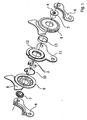
- FIG. 1 shows an exploded view of an embodiment of the adjusting device according to the invention.
- This adjusting device has a backrest adapter 8 and a seat adapter 11. With the retaining plates 6, the seat adapter 11 is attached to the vehicle seat, bolted here.
- the backrest adapter 8 is connected to the backrest of the vehicle seat, preferably welded.
- the person skilled in the art recognizes that these functionalities of the two adapters 8, 11 can also be reversed.
- the relative position of the backrest adapter 8 relative to the seat adapter 11 is determined by means of an eccentric 1, which has two wedges 2. These two wedges 2 are preferably arranged symmetrically and particularly preferably mirror-symmetrically to a straight line passing through the axis of rotation D.
- the two wedges are pressed apart with an energy store, here a spring 10, preferably an annular spring whose ends engage in notches in the wedges 2.
- the energy storage 10 is part of the eccentric.
- the wedges 2 are at least partially disposed in a bearing shell 13 and are supported on this.
- the bearing shell 13 the friction between the eccentric and the seat adapter 11 can be reduced and a uniform concentricity of the eccentric can be achieved.
- the device according to the invention on a drive pin 4, which is driven manually or by motor.
- This drive pin 4 transmits its rotary motion, as will be described in more detail below, on the Eccentric 1, so that when turning the drive 4 of the externally toothed seat adapter 11 rolls in the internally toothed backrest adapter 8.
- the drive pin 4 is connected to a sleeve 7, preferably welded.
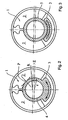
- FIG. 2 the eccentric 1 of the device according to the invention is shown.
- the eccentric serves, as already mentioned, to drive the externally toothed internal gear within an internally toothed, at least one tooth more outer gear. It is therefore a so-called wobble gear.
- the eccentric is formed by wedges 2, which are pressed apart to compensate for Tangentialspiel in the wobble mechanism by a spring 10, not shown here.
- the drive of the wedges 2 in the one or opposite direction of rotation takes place at least temporarily by a driver 3, which is integrally formed on the drive bolt 4.
- an immediate reaction of the transmission is desirable. According to the invention, therefore, it is intended to exert a torque from the rotating drive bolt 4 on the relevant wedge 2 by friction, even before the contact of the wedge 2 with the driver 3.
- the arc-shaped wedges 2 therefore have an inner radius of curvature R, which is greater than the outer radius r of the drive pin 4.
- Approximately in the range of a 1: 2 division of the inner arc of the driver close wedge 2 mit psychologyfernen a contact point P or, forms a line of contact , over which the assigned (here the right) wedge 2 is released from its clamping already before contact with the driver 3 and displaced in the direction of rotation of the drive pin 4.
- the eccentric 1 causes a tumbling motion between the two Fittings 8, 11.
- the wedges 2 serve not only as a drive transmission means but to lock the eccentric in the non-driven state in its respective position in the event that a torque is transmitted from the internal gear 9 to the external gear 12; that is, for example, in an accident, a torque is transmitted from the backrest to the eccentric 1.
- FIG. 4 show a first construction of an adjusting device according to the invention.
- the essential parts of the mechanism are the seat part side holding plates 6, a socket 7, the backrest adapter 8 with internal gear 9, the spring 10, which spreads the wedges 2, the seat part adapter 11 with the externally toothed gears 12, the bearing shell 13 and the drive pin 4 with the bushing 7 rotates in this case together with the collar provided with a drive pin 4, with which it is rotatably connected, for example by welding.
- FIG. 5 Another embodiment is in FIG. 5 shown.
- This embodiment corresponds essentially to the embodiment according to FIG. 4 , wherein in this embodiment, the drive pin 4 rotates in two bearing shells 14, 15 and welded at each end for axial securing with end plates 16, 17.
- FIG. 6 shows a further embodiment of the adjusting device according to the invention.
- the adjusting device on a bearing 18 which is connected to the backrest adapter 8.
- This drive has on its inner side form and / or adhesion means 4 ', for example, teeth, which cooperate with corresponding form and / or adhesion means of a motor drive.
- the adjusting device can be constructed in the manner of a laminate; that is, a plurality of backrest adapter 8 and / or seat part adapter 11, which are arranged in layers.
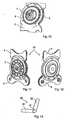
- Reference numeral 1 denotes a drive element for arrangement in a power-driven adjusting device according to the invention.
- Reference numeral 2 denotes a guide bush for arrangement in a power-driven adjusting device according to the invention.
- Reference numeral 3 denotes a central element for arrangement in a power-driven adjusting device according to the invention.
- FIG. 8 a part of the adjusting device 10 according to the invention is shown schematically.
- a first fitting part 4 is shown in addition to the central element 3 and the drive element 1.
- FIG. 9 is a sectional view schematically represented by the adjusting device 10 according to the invention.
- an axially extended (along the axis of rotation of the adjusting 10 extending) overlap region 5 of the central element 3 and the drive element 1 can be seen.
- the cohesive connection in particular a weld and in particular a laser welding
- the guide bush 2 is connected or welded to the drive element 1 and / or to the first or second fitting part 4, 9, so that the adjustment device 10 has a further improved behavior against forces which act in the sense of an axial disassembly of the adjusting device 10.
- FIG. 14 is a variant of the in the FIGS. 7, 8 and 9 shown adjusting device 10 according to the invention shown in section through the adjusting device 10 according to the invention schematically.
- like reference numerals from previous figures denote the same components or parts of the adjusting device 10.
- FIG. 9 illustrated embodiment of the adjusting device 10 according to the invention it is in the embodiment according to the FIG. 14 provided that instead of in FIG. 9 shown collar 1.1 of the drive element 1, an axial end 1.2 of the drive element 1 projects into a substantially circular groove or recess 3.1 of the central element 3.
- FIG. 10 is a perspective view of a partially assembled adjusting device according to the invention shown schematically.
- the adjusting device according to the in the document WO 2006/040303 A2 assembled manner namely with eccentric means 6 in the form of, for example, wedges, a spring, gear plates 8 and a second fitting part 9 and a guide bush.
- FIGS. 11 and 12 two perspective views of the fully assembled power-driven adjusting device 10 according to the invention are shown schematically.
- the guide bush 2 is welded to the drive element and / or to the first fitting part 4 or the second fitting part 9.
- the adjusting device 10 is provided on a vehicle seat as the vehicle component and that the adjusting device 10 is provided for the inclination adjustment of the backrest 20 of a vehicle seat 40 which also has a seat part 30, in addition to the backrest 20. This is schematically in FIG. 13 shown.
Landscapes
- Engineering & Computer Science (AREA)
- Aviation & Aerospace Engineering (AREA)
- Transportation (AREA)
- Mechanical Engineering (AREA)
- Chairs For Special Purposes, Such As Reclining Chairs (AREA)
- Seats For Vehicles (AREA)
Applications Claiming Priority (4)
| Application Number | Priority Date | Filing Date | Title |
|---|---|---|---|
| DE102007001617 | 2007-01-04 | ||
| PCT/US2007/073034 WO2009008884A1 (en) | 2007-07-09 | 2007-07-09 | Recliner mechanism for vehicle seat |
| DE102007039024.8A DE102007039024B4 (de) | 2007-01-04 | 2007-08-17 | Verstelleinrichtung für eine Fahrzeugkomponente |
| PCT/EP2008/000005 WO2008080999A1 (de) | 2007-01-04 | 2008-01-02 | Verstelleinrichtung für einen fahrzeugsitz |
Publications (2)
| Publication Number | Publication Date |
|---|---|
| EP2107977A1 EP2107977A1 (de) | 2009-10-14 |
| EP2107977B1 true EP2107977B1 (de) | 2016-05-04 |
Family
ID=39229592
Family Applications (1)
| Application Number | Title | Priority Date | Filing Date |
|---|---|---|---|
| EP08700963.5A Not-in-force EP2107977B1 (de) | 2007-01-04 | 2008-01-02 | Verstelleinrichtung für einen fahrzeugsitz |
Country Status (4)
| Country | Link |
|---|---|
| EP (1) | EP2107977B1 (pl) |
| JP (2) | JP2010514527A (pl) |
| PL (1) | PL2107977T3 (pl) |
| WO (1) | WO2008080999A1 (pl) |
Families Citing this family (4)
| Publication number | Priority date | Publication date | Assignee | Title |
|---|---|---|---|---|
| DE102008024853B4 (de) * | 2008-05-19 | 2024-03-07 | Keiper Seating Mechanisms Co., Ltd. | Beschlag für einen Fahrzeugsitz, Fahrzeugsitz und Verfahren zur Erzeugung einer axialen Sicherung |
| JP2013501683A (ja) * | 2009-08-12 | 2013-01-17 | ジョンソン コントロールズ テクノロジー カンパニー | 連続的に係合するリクライナ・フリープレイ・システムおよび精密打ち抜きギアハブ |
| DE102010018952B4 (de) | 2010-04-28 | 2013-03-14 | Keiper Gmbh & Co. Kg | Beschlag für einen Fahrzeugsitz, Fahrzeugsitz und Verfahren zum Zusammenbau eines Beschlags |
| JP7524818B2 (ja) * | 2021-04-09 | 2024-07-30 | トヨタ紡織株式会社 | リクライニング装置 |
Family Cites Families (6)
| Publication number | Priority date | Publication date | Assignee | Title |
|---|---|---|---|---|
| DE3941215C2 (de) * | 1989-12-14 | 1995-07-20 | Keiper Recaro Gmbh Co | Rücklehnenverstellbeschlag für Sitze, insbesondere Kraftfahrzeugsitze |
| DE4119980C2 (de) * | 1991-06-18 | 1997-08-14 | Keiper Recaro Gmbh Co | Lehneneinstellbeschlag für Sitze, insbesondere Kraftfahrzeugsitze |
| DE19548809C1 (de) * | 1995-12-27 | 1997-05-22 | Keiper Recaro Gmbh Co | Ver- und Feststelleinrichtung für Sitze, wie Kraftfahrzeugsitze, zur Verstellung der Rückenlehne |
| DE19904300C1 (de) * | 1999-01-28 | 2000-08-03 | Keiper Gmbh & Co | Rastbeschlag für einen Fahrzeugsitz |
| DE19938666C5 (de) * | 1999-08-14 | 2008-01-03 | Keiper Gmbh & Co.Kg | Verstellbeschlag für Sitze mit neigungseinstellbarer Lehne, insbesondere für Kraftfahzeugsitze |
| JP4538289B2 (ja) * | 2004-09-29 | 2010-09-08 | 富士機工株式会社 | 自動車シートのリクライニング装置 |
-
2008
- 2008-01-02 EP EP08700963.5A patent/EP2107977B1/de not_active Not-in-force
- 2008-01-02 JP JP2009544396A patent/JP2010514527A/ja active Pending
- 2008-01-02 PL PL08700963.5T patent/PL2107977T3/pl unknown
- 2008-01-02 WO PCT/EP2008/000005 patent/WO2008080999A1/de not_active Ceased
-
2014
- 2014-09-09 JP JP2014183440A patent/JP5908040B2/ja not_active Expired - Fee Related
Also Published As
| Publication number | Publication date |
|---|---|
| WO2008080999A1 (de) | 2008-07-10 |
| JP2010514527A (ja) | 2010-05-06 |
| EP2107977A1 (de) | 2009-10-14 |
| PL2107977T3 (pl) | 2016-11-30 |
| JP2015037560A (ja) | 2015-02-26 |
| JP5908040B2 (ja) | 2016-04-26 |
Similar Documents
| Publication | Publication Date | Title |
|---|---|---|
| EP1713659B1 (de) | Beschlag für einen fahrzeugsitz | |
| EP1202870B2 (de) | Verstellbeschlag für sitze mit neigungseinstellbarer lehne, insbesondere für kraftfahrzeugsitze | |
| EP2694355B1 (de) | Elektromechanische servolenkung mit spielausgleich für das schneckenradgetriebe | |
| EP2499018A1 (de) | Beschlag für einen fahrzeugsitz | |
| EP2345569B1 (de) | Schraubradgetriebe für eine Lenkung eines Kraftfahrzeugs | |
| DE102006044490A1 (de) | Beschlag für einen Fahrzeugsitz | |
| WO2013152995A1 (de) | Lenkgetriebe | |
| EP2563618B1 (de) | Beschlag für einen fahrzeugsitz | |
| EP3983701B1 (de) | Linearantrieb | |
| DE102013217161B4 (de) | Lineareinheit | |
| EP3634834A1 (de) | Loslager, lenkgetriebe und lenksystem | |
| EP2107977B1 (de) | Verstelleinrichtung für einen fahrzeugsitz | |
| EP3541685A1 (de) | Lenksystem | |
| DE102009038735B4 (de) | Verstellvorrichtung für eine Fahrzeugkomponente | |
| DE102009002478B4 (de) | Ver- und Feststellvorrichtung eines Verstellbeschlages | |
| EP2838756A1 (de) | Bremsvorrichtung für eine direkt elektromechanisch aktuierte planetengetriebeanordnung eines sitzverstellmechanismus und verfahren zum betrieb einer bremsvorrichtung | |
| EP2748028A1 (de) | Verstellbeschlag mit einem axialsperrsystem zur ablaufsicherung | |
| DE102004007045B3 (de) | Beschlag für einen Fahrzeugsitz | |
| EP2580086B1 (de) | Beschlag für einen fahrzeugsitz | |
| DE69704202T2 (de) | Neigungsverstellungsmechanismus für einen Sitz | |
| EP1879758B1 (de) | Geteilter elektromechanischer kraftfahrzeugstabilisator mit blockiereinrichtung und verfahren zur wankstabilisierung bei ausfall oder abschaltung des aktiven kraftfahrzeugstabilisators | |
| DE4241531C1 (de) | Servosteuerung, insbesondere Servolenkung für Kraftfahrzeuge | |
| WO2012136341A2 (de) | Beschlag für einen fahrzeugsitz | |
| DE102007039024B4 (de) | Verstelleinrichtung für eine Fahrzeugkomponente | |
| WO2019134814A1 (de) | Lenkgetriebe für ein kraftfahrzeug |
Legal Events
| Date | Code | Title | Description |
|---|---|---|---|
| PUAI | Public reference made under article 153(3) epc to a published international application that has entered the european phase |
Free format text: ORIGINAL CODE: 0009012 |
|
| 17P | Request for examination filed |
Effective date: 20090804 |
|
| AK | Designated contracting states |
Kind code of ref document: A1 Designated state(s): AT BE BG CH CY CZ DE DK EE ES FI FR GB GR HR HU IE IS IT LI LT LU LV MC MT NL NO PL PT RO SE SI SK TR |
|
| RIN1 | Information on inventor provided before grant (corrected) |
Inventor name: KIENKE, INGO Inventor name: KIRUBAHARAN, ALBERT, REGINOLD Inventor name: OTTO, JUERGEN Inventor name: BUDWEG, MARIO |
|
| DAX | Request for extension of the european patent (deleted) | ||
| 17Q | First examination report despatched |
Effective date: 20120301 |
|
| GRAP | Despatch of communication of intention to grant a patent |
Free format text: ORIGINAL CODE: EPIDOSNIGR1 |
|
| INTG | Intention to grant announced |
Effective date: 20151124 |
|
| GRAS | Grant fee paid |
Free format text: ORIGINAL CODE: EPIDOSNIGR3 |
|
| GRAA | (expected) grant |
Free format text: ORIGINAL CODE: 0009210 |
|
| AK | Designated contracting states |
Kind code of ref document: B1 Designated state(s): AT BE BG CH CY CZ DE DK EE ES FI FR GB GR HR HU IE IS IT LI LT LU LV MC MT NL NO PL PT RO SE SI SK TR |
|
| REG | Reference to a national code |
Ref country code: GB Ref legal event code: FG4D Free format text: NOT ENGLISH |
|
| REG | Reference to a national code |
Ref country code: CH Ref legal event code: EP |
|
| REG | Reference to a national code |
Ref country code: AT Ref legal event code: REF Ref document number: 796593 Country of ref document: AT Kind code of ref document: T Effective date: 20160515 |
|
| REG | Reference to a national code |
Ref country code: IE Ref legal event code: FG4D Free format text: LANGUAGE OF EP DOCUMENT: GERMAN |
|
| REG | Reference to a national code |
Ref country code: DE Ref legal event code: R096 Ref document number: 502008014159 Country of ref document: DE |
|
| REG | Reference to a national code |
Ref country code: NL Ref legal event code: MP Effective date: 20160504 |
|
| REG | Reference to a national code |
Ref country code: LT Ref legal event code: MG4D |
|
| PG25 | Lapsed in a contracting state [announced via postgrant information from national office to epo] |
Ref country code: LT Free format text: LAPSE BECAUSE OF FAILURE TO SUBMIT A TRANSLATION OF THE DESCRIPTION OR TO PAY THE FEE WITHIN THE PRESCRIBED TIME-LIMIT Effective date: 20160504 Ref country code: FI Free format text: LAPSE BECAUSE OF FAILURE TO SUBMIT A TRANSLATION OF THE DESCRIPTION OR TO PAY THE FEE WITHIN THE PRESCRIBED TIME-LIMIT Effective date: 20160504 Ref country code: NO Free format text: LAPSE BECAUSE OF FAILURE TO SUBMIT A TRANSLATION OF THE DESCRIPTION OR TO PAY THE FEE WITHIN THE PRESCRIBED TIME-LIMIT Effective date: 20160804 Ref country code: NL Free format text: LAPSE BECAUSE OF FAILURE TO SUBMIT A TRANSLATION OF THE DESCRIPTION OR TO PAY THE FEE WITHIN THE PRESCRIBED TIME-LIMIT Effective date: 20160504 |
|
| PG25 | Lapsed in a contracting state [announced via postgrant information from national office to epo] |
Ref country code: HR Free format text: LAPSE BECAUSE OF FAILURE TO SUBMIT A TRANSLATION OF THE DESCRIPTION OR TO PAY THE FEE WITHIN THE PRESCRIBED TIME-LIMIT Effective date: 20160504 Ref country code: PT Free format text: LAPSE BECAUSE OF FAILURE TO SUBMIT A TRANSLATION OF THE DESCRIPTION OR TO PAY THE FEE WITHIN THE PRESCRIBED TIME-LIMIT Effective date: 20160905 Ref country code: LV Free format text: LAPSE BECAUSE OF FAILURE TO SUBMIT A TRANSLATION OF THE DESCRIPTION OR TO PAY THE FEE WITHIN THE PRESCRIBED TIME-LIMIT Effective date: 20160504 Ref country code: SE Free format text: LAPSE BECAUSE OF FAILURE TO SUBMIT A TRANSLATION OF THE DESCRIPTION OR TO PAY THE FEE WITHIN THE PRESCRIBED TIME-LIMIT Effective date: 20160504 Ref country code: GR Free format text: LAPSE BECAUSE OF FAILURE TO SUBMIT A TRANSLATION OF THE DESCRIPTION OR TO PAY THE FEE WITHIN THE PRESCRIBED TIME-LIMIT Effective date: 20160805 Ref country code: ES Free format text: LAPSE BECAUSE OF FAILURE TO SUBMIT A TRANSLATION OF THE DESCRIPTION OR TO PAY THE FEE WITHIN THE PRESCRIBED TIME-LIMIT Effective date: 20160504 |
|
| PG25 | Lapsed in a contracting state [announced via postgrant information from national office to epo] |
Ref country code: IT Free format text: LAPSE BECAUSE OF FAILURE TO SUBMIT A TRANSLATION OF THE DESCRIPTION OR TO PAY THE FEE WITHIN THE PRESCRIBED TIME-LIMIT Effective date: 20160504 |
|
| REG | Reference to a national code |
Ref country code: FR Ref legal event code: PLFP Year of fee payment: 10 |
|
| PG25 | Lapsed in a contracting state [announced via postgrant information from national office to epo] |
Ref country code: DK Free format text: LAPSE BECAUSE OF FAILURE TO SUBMIT A TRANSLATION OF THE DESCRIPTION OR TO PAY THE FEE WITHIN THE PRESCRIBED TIME-LIMIT Effective date: 20160504 Ref country code: RO Free format text: LAPSE BECAUSE OF FAILURE TO SUBMIT A TRANSLATION OF THE DESCRIPTION OR TO PAY THE FEE WITHIN THE PRESCRIBED TIME-LIMIT Effective date: 20160504 Ref country code: EE Free format text: LAPSE BECAUSE OF FAILURE TO SUBMIT A TRANSLATION OF THE DESCRIPTION OR TO PAY THE FEE WITHIN THE PRESCRIBED TIME-LIMIT Effective date: 20160504 |
|
| REG | Reference to a national code |
Ref country code: DE Ref legal event code: R097 Ref document number: 502008014159 Country of ref document: DE |
|
| PLBE | No opposition filed within time limit |
Free format text: ORIGINAL CODE: 0009261 |
|
| STAA | Information on the status of an ep patent application or granted ep patent |
Free format text: STATUS: NO OPPOSITION FILED WITHIN TIME LIMIT |
|
| 26N | No opposition filed |
Effective date: 20170207 |
|
| REG | Reference to a national code |
Ref country code: DE Ref legal event code: R081 Ref document number: 502008014159 Country of ref document: DE Owner name: ADIENT LUXEMBOURG HOLDING S.A.R.L., LU Free format text: FORMER OWNER: JOHNSON CONTROLS GMBH, 51399 BURSCHEID, DE Ref country code: DE Ref legal event code: R081 Ref document number: 502008014159 Country of ref document: DE Owner name: ADIENT LUXEMBOURG HOLDING S.A R.L., LU Free format text: FORMER OWNER: JOHNSON CONTROLS GMBH, 51399 BURSCHEID, DE |
|
| PG25 | Lapsed in a contracting state [announced via postgrant information from national office to epo] |
Ref country code: SI Free format text: LAPSE BECAUSE OF FAILURE TO SUBMIT A TRANSLATION OF THE DESCRIPTION OR TO PAY THE FEE WITHIN THE PRESCRIBED TIME-LIMIT Effective date: 20160504 Ref country code: BE Free format text: LAPSE BECAUSE OF NON-PAYMENT OF DUE FEES Effective date: 20170131 |
|
| REG | Reference to a national code |
Ref country code: CH Ref legal event code: PL |
|
| GBPC | Gb: european patent ceased through non-payment of renewal fee |
Effective date: 20170102 |
|
| PG25 | Lapsed in a contracting state [announced via postgrant information from national office to epo] |
Ref country code: MC Free format text: LAPSE BECAUSE OF FAILURE TO SUBMIT A TRANSLATION OF THE DESCRIPTION OR TO PAY THE FEE WITHIN THE PRESCRIBED TIME-LIMIT Effective date: 20160504 |
|
| PG25 | Lapsed in a contracting state [announced via postgrant information from national office to epo] |
Ref country code: CH Free format text: LAPSE BECAUSE OF NON-PAYMENT OF DUE FEES Effective date: 20170131 Ref country code: LI Free format text: LAPSE BECAUSE OF NON-PAYMENT OF DUE FEES Effective date: 20170131 |
|
| REG | Reference to a national code |
Ref country code: IE Ref legal event code: MM4A |
|
| PG25 | Lapsed in a contracting state [announced via postgrant information from national office to epo] |
Ref country code: GB Free format text: LAPSE BECAUSE OF NON-PAYMENT OF DUE FEES Effective date: 20170102 Ref country code: LU Free format text: LAPSE BECAUSE OF NON-PAYMENT OF DUE FEES Effective date: 20170102 |
|
| REG | Reference to a national code |
Ref country code: FR Ref legal event code: PLFP Year of fee payment: 11 |
|
| PGFP | Annual fee paid to national office [announced via postgrant information from national office to epo] |
Ref country code: CZ Payment date: 20171228 Year of fee payment: 11 Ref country code: SK Payment date: 20171228 Year of fee payment: 11 |
|
| REG | Reference to a national code |
Ref country code: BE Ref legal event code: MM Effective date: 20170131 |
|
| PG25 | Lapsed in a contracting state [announced via postgrant information from national office to epo] |
Ref country code: IE Free format text: LAPSE BECAUSE OF NON-PAYMENT OF DUE FEES Effective date: 20170102 |
|
| PGFP | Annual fee paid to national office [announced via postgrant information from national office to epo] |
Ref country code: PL Payment date: 20171229 Year of fee payment: 11 |
|
| REG | Reference to a national code |
Ref country code: AT Ref legal event code: MM01 Ref document number: 796593 Country of ref document: AT Kind code of ref document: T Effective date: 20170102 |
|
| REG | Reference to a national code |
Ref country code: DE Ref legal event code: R081 Ref document number: 502008014159 Country of ref document: DE Owner name: ADIENT LUXEMBOURG HOLDING S.A R.L., LU Free format text: FORMER OWNER: ADIENT LUXEMBOURG HOLDING S.A.R.L., LUXEMBOURG, LU |
|
| PGFP | Annual fee paid to national office [announced via postgrant information from national office to epo] |
Ref country code: DE Payment date: 20180131 Year of fee payment: 11 |
|
| PG25 | Lapsed in a contracting state [announced via postgrant information from national office to epo] |
Ref country code: AT Free format text: LAPSE BECAUSE OF NON-PAYMENT OF DUE FEES Effective date: 20170102 |
|
| PGFP | Annual fee paid to national office [announced via postgrant information from national office to epo] |
Ref country code: FR Payment date: 20180119 Year of fee payment: 11 |
|
| PG25 | Lapsed in a contracting state [announced via postgrant information from national office to epo] |
Ref country code: MT Free format text: LAPSE BECAUSE OF FAILURE TO SUBMIT A TRANSLATION OF THE DESCRIPTION OR TO PAY THE FEE WITHIN THE PRESCRIBED TIME-LIMIT Effective date: 20160504 |
|
| PG25 | Lapsed in a contracting state [announced via postgrant information from national office to epo] |
Ref country code: HU Free format text: LAPSE BECAUSE OF FAILURE TO SUBMIT A TRANSLATION OF THE DESCRIPTION OR TO PAY THE FEE WITHIN THE PRESCRIBED TIME-LIMIT; INVALID AB INITIO Effective date: 20080102 |
|
| PG25 | Lapsed in a contracting state [announced via postgrant information from national office to epo] |
Ref country code: CZ Free format text: LAPSE BECAUSE OF NON-PAYMENT OF DUE FEES Effective date: 20190102 |
|
| REG | Reference to a national code |
Ref country code: DE Ref legal event code: R119 Ref document number: 502008014159 Country of ref document: DE |
|
| PG25 | Lapsed in a contracting state [announced via postgrant information from national office to epo] |
Ref country code: BG Free format text: LAPSE BECAUSE OF FAILURE TO SUBMIT A TRANSLATION OF THE DESCRIPTION OR TO PAY THE FEE WITHIN THE PRESCRIBED TIME-LIMIT Effective date: 20160504 |
|
| REG | Reference to a national code |
Ref country code: SK Ref legal event code: MM4A Ref document number: E 21744 Country of ref document: SK Effective date: 20190102 |
|
| PG25 | Lapsed in a contracting state [announced via postgrant information from national office to epo] |
Ref country code: SK Free format text: LAPSE BECAUSE OF NON-PAYMENT OF DUE FEES Effective date: 20190102 Ref country code: FR Free format text: LAPSE BECAUSE OF NON-PAYMENT OF DUE FEES Effective date: 20190131 Ref country code: DE Free format text: LAPSE BECAUSE OF NON-PAYMENT OF DUE FEES Effective date: 20190801 Ref country code: CY Free format text: LAPSE BECAUSE OF NON-PAYMENT OF DUE FEES Effective date: 20160504 |
|
| PG25 | Lapsed in a contracting state [announced via postgrant information from national office to epo] |
Ref country code: TR Free format text: LAPSE BECAUSE OF FAILURE TO SUBMIT A TRANSLATION OF THE DESCRIPTION OR TO PAY THE FEE WITHIN THE PRESCRIBED TIME-LIMIT Effective date: 20160504 |
|
| PG25 | Lapsed in a contracting state [announced via postgrant information from national office to epo] |
Ref country code: IS Free format text: LAPSE BECAUSE OF FAILURE TO SUBMIT A TRANSLATION OF THE DESCRIPTION OR TO PAY THE FEE WITHIN THE PRESCRIBED TIME-LIMIT Effective date: 20160904 |
|
| PG25 | Lapsed in a contracting state [announced via postgrant information from national office to epo] |
Ref country code: PL Free format text: LAPSE BECAUSE OF NON-PAYMENT OF DUE FEES Effective date: 20190102 |