EP2107970B1 - Wischerblatthalter - Google Patents
Wischerblatthalter Download PDFInfo
- Publication number
- EP2107970B1 EP2107970B1 EP08707033.0A EP08707033A EP2107970B1 EP 2107970 B1 EP2107970 B1 EP 2107970B1 EP 08707033 A EP08707033 A EP 08707033A EP 2107970 B1 EP2107970 B1 EP 2107970B1
- Authority
- EP
- European Patent Office
- Prior art keywords
- wiper blade
- body member
- blade holder
- attachment
- mounting
- Prior art date
- Legal status (The legal status is an assumption and is not a legal conclusion. Google has not performed a legal analysis and makes no representation as to the accuracy of the status listed.)
- Active
Links
Images


Classifications
-
- B—PERFORMING OPERATIONS; TRANSPORTING
- B41—PRINTING; LINING MACHINES; TYPEWRITERS; STAMPS
- B41F—PRINTING MACHINES OR PRESSES
- B41F15/00—Screen printers
- B41F15/14—Details
- B41F15/40—Inking units
- B41F15/42—Inking units comprising squeegees or doctors
- B41F15/426—Inking units comprising squeegees or doctors the squeegees or doctors being magnetically attracted
-
- B—PERFORMING OPERATIONS; TRANSPORTING
- B41—PRINTING; LINING MACHINES; TYPEWRITERS; STAMPS
- B41F—PRINTING MACHINES OR PRESSES
- B41F15/00—Screen printers
- B41F15/14—Details
- B41F15/44—Squeegees or doctors
Definitions
- the present invention relates to a wiper blade holder for use in a screen printing machine and a wiper blade therefor, with such wiper blades often being referred to as squeegee blades.
- a conventional wiper blade holder is illustrated in Figure 1 .
- the wiper blade holder comprises an elongate body member 1, which includes a pair of screw studs 3 for fixing the wiper blade holder to a screen printing machine, and a wiper blade 7, which is clamped to the body member 1 by a clamping bar 9 and a plurality of fixing screws 11 which are screwed to the body member 1 at spaced locations along the length of the clamping bar 9.
- Wiper blades are subject to wear and prone to damage during use, and, if not replaced, would result in a degradation in the print quality. Thus, it is necessary regularly to replace wiper blades.
- the printing material typically solder paste
- the fixing screws 11 which makes it difficult to remove the wiper blade 7.
- This accumulation of the printing material is particularly problematic where using both lead-free and lead-based solder pastes with the one wiper blade holder, as cross-contamination can occur.
- a conventional wiper blade holder is disclosed in US 6267818 B1 .
- the present invention provides a wiper blade holder for holding a wiper blade for use in a screen printing machine, the wiper blade holder comprising: a body unit comprising a body member which includes a mounting surface to which a wiper blade is mounted; at least one mounting fixture which is attached to the body unit for mounting the wiper blade holder to a screen printing machine; and at least one magnet which acts to hold the wiper blade to the mounting surface of the body unit.
- the body member includes an attachment slot in an upper edge thereof, in which the at least one mounting fixture is slideably disposed, such as to allow for positional adjustment of the at least one mounting fixture.
- the attachment slot comprises an elongate slot which extends along the length of the body member and in which the at least one mounting fixture is captively located.
- each mounting fixture comprises an attachment member which provides means of attachment to a screen printing machine, a clamping element which is slideably disposed in the attachment slot in the upper edge of the body member, and at least one fixing element which couples the attachment member and the clamping element, such as to clamp the attachment member to the body member.
- the clamping element comprises a plate.
- the at least one fixing element comprises a threaded screw which threadedly engages the clamping element, such as to clamp the attachment member to the upper edge of the body member.
- each mounting fixture comprises a plurality of fixing elements.
- the attachment member comprises a body part and an attachment element which extends from the body part and provides means of attachment to a screen printing machine.
- the attachment element comprises a stud.
- the attachment element has an attachment axis and the body part has a lower, engagement surface which engages the upper edge of the body member when clamped thereto, such that the plane of the engagement surface relative to the axis of the attachment element defines the inclination of the mounting surface of the body member relative to the at least one mounting fixture.
- the body part includes a projection on the engagement surface thereof, which is a sliding fit in the attachment slot in the body member.
- the mounting surface extends along the length of a front face of the body member.
- the mounting surface is inclined rearwardly and downwardly from the front face of the body member.
- the body member includes a fixing slot in the front face thereof, which defines an upper edge of the mounting surface, such as to define a captive lip for receiving an upper edge of the wiper blade and aligning the wiper blade relative to the body member.
- the at least one magnet is disposed to the body member.
- the wiper blade holder comprises: a plurality of magnets which are disposed along the length of the body member.
- the body member includes a plurality of recesses which house respective ones of the magnets.
- the recesses are disposed at spaced locations along the length of the body member.
- the recesses comprise blind recesses which open to a rear face of the body member.
- the recesses are each configured such as to leave a shim section at the mounting surface of the body member, behind which respective ones of the magnets are disposed.
- the at least one magnet comprises a permanent magnet.
- the body unit comprises a retaining plate of a magnetically-susceptible material, which, by the action of the at least one magnet, acts to clamp the wiper blade to the mounting surface of the body member.
- the retaining plate is formed of a ferromagnetic material.
- the wiper blade holder comprises: a plurality of mounting fixtures.
- the present invention also extends to a wiper blade assembly for use in a screen printing machine, comprising: the above-described wiper blade holder; and a wiper blade which is disposed to the mounting surface of the body member.
- the wiper blade is formed of a material which is magnetically susceptible to the at least one magnet.
- the wiper blade is formed of a ferromagnetic material.
- the wiper blade is formed of a material which is not magnetically susceptible to the at least one magnet.
- the wiper blade is formed of a non-ferromagnetic material.
- the present invention also extends to a wiper blade assembly for use in a screen printing machine, comprising: the above-described wiper blade holder; and a wiper blade which is disposed to the mounting surface of the body member.
- the wiper blade is formed of a material which is magnetically susceptible to the at least one magnet.
- the wiper blade is formed of a ferromagnetic material.
- the wiper blade is formed of a material which is not magnetically susceptible to the at least one magnet.
- the wiper blade is formed of a non-ferromagnetic material.
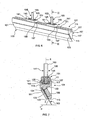
- FIGS 1 to 5 illustrate a wiper blade holder in accordance with a first embodiment of the present invention.
- the wiper blade holder comprises a body unit 101, in this embodiment an elongate unit, a wiper blade 103, in this embodiment an elongate blade, which is formed of a magnetically-susceptible material, here of a ferromagnetic metal, and attached to the body unit 101, and a plurality of mounting fixtures 105 which are attached to the body unit 101 for mounting the wiper blade holder to a screen printing machine.
- the body unit 101 comprises a body member 107, and at least one, in this embodiment a plurality of magnets 109 for attaching the wiper blade 103 to the body member 107, as will be described in more detail hereinbelow.
- the body member 107 includes an upper edge 111 to which the mounting fixtures 105 are disposed, a lower, downwardly-directed edge 113, a front face 115 which supports the wiper blade 103 and a rear face 117.
- the upper edge 111 includes an attachment slot 121 in which the mounting fixtures 105 are slideably disposed, such as to allow the positions of the mounting fixtures 105 to be adjusted according to the requirements of the screen printing machine.
- the attachment slot 121 comprises an elongate slot which extends along the length of the body member 107, and is a T-shaped slot, in which the mounting fixtures 105 are captively located.
- the body member 107 further includes a mounting surface 123, in this embodiment an elongate surface, which extends along the length of the front face 115 thereof, to which the wiper blade 103 is attached.
- the mounting surface 123 is inclined rearwardly and downwardly from the front face 115 towards the rear face 117.
- the body member 107 further includes a fixing slot 131, in this embodiment an elongate slot, which is located in the front face 115 at the upper edge of the mounting surface 123, such as to define a captive lip for receiving an upper edge of the wiper blade 103 and aligning the wiper blade 103 relative to the body member 107.
- the fixing slot 131 acts to prevent the upper edge of the wiper blade 103 from peeling away from the mounting surface 123, and thus be separated from the magnets 109, by a pivoting force which is created about the lower edge 113 of the body member 101 when displacing the wiper blade holder.
- the body member 107 further includes a plurality of recesses 133, in this embodiment blind circular recesses, which receive respective ones of the magnets 109 and are disposed at spaced locations along the length thereof and open to the rear face 117.
- the recesses 133 are evenly spaced along the length of the body member 107, such that a substantially-uniform holding force is achieved along the length of the attached wiper blade 103.
- the recesses 133 are configured such as to leave a thin section 135, here in the form of a shim having a thickness of about 0.7 mm, at the mounting surface 123.
- the mounting surface 123 presents a smooth, continuous surface which is easily cleaned and yet the magnets 109 present a sufficient holding force to maintain the wiper blade 103 attached to the body member 107.
- the body member 107 is formed from an extrusion, typically an aluminium extrusion.
- the body member 107 can be coated with a low-friction or non-stick coating, such as of Teflon (RTM), which facilitates cleaning of the body member 107.
- RTM Teflon
- the magnets 109 are disposed in respective ones of the recesses 133 in the body member 107, such as to abut the respective shim sections 135.
- the magnets 109 present a relatively large surface area and have a diameter of about 19.05 mm (0.75 inch) and thickness of about 4.75 mm (0.187 inch).
- the magnets 109 are neodynium magnets, as available from Northwest Magnets (Portland, Oregon, USA).
- the mounting fixtures 105 each comprise an attachment member 141 which provides the means of attachment to a screen printing machine, a clamping element 143, in this embodiment a plate, which is slideably disposed in the attachment slot 121 in the upper edge 111 of the body member 107, and at least one, in this embodiment a pair of fixing elements 145, here threaded screws, which extend through the attachment member 141 and threadedly engage the clamping element 143, such that, on tightening, the fixing elements 145 act to clamp the attachment member 141 to the upper edge 111 of the body member 107.
- a pair of fixing elements 145 here threaded screws
- the attachment member 141 comprises a body part 151 and an attachment element 153, in this embodiment a screw stud, which extends from the body part 151 and provides the means of attachment to a screen printing machine.
- the body part 151 has a lower, engagement surface 155 which engages the upper edge 111 of the body member 107 when clamped thereto.
- the engagement surface 155 extends orthogonally to the axis X of the attachment element 153, such that, when the attachment element 153 is vertically directed, the wiper blade 103 encloses a predetermined, acute printing angle ⁇ with the surface of a printing screen P over which the wiper blade holder is moved.
- the printing angle ⁇ is about 60 degrees.
- the body part 151 could be adapted such that the engagement surface 155 extends at any required angle to the axis X of the attachment element 153.
- the wiper blade 103 can be configured to enclose any required angle ⁇ with the surface of a printing screen P over which the wiper blade holder is moved.
- the printing angle ⁇ is about 45 degrees.
- the body part 151 includes a projection 157, here of elongate form, on the lower, engagement surface 155 thereof, which is a sliding fit in the attachment slot 121 in the body member 107.
- the attachment member 141 can be readily aligned to the upper edge 111 of the body member 107.
- FIGS. 6 and 7 illustrate a wiper blade holder in accordance with a second embodiment of the present invention.
- the wiper blade holder of this embodiment is quite similar to the wiper blade holder of the above-described first embodiment, and thus, in order to avoid unnecessary duplication of description, only the differences will be described in detail, with like reference signs designating like parts.
- the wiper blade holder of this embodiment differs from that of the above-described first embodiment in that the body unit 101 further comprises a retaining plate 161 of a magnetically-susceptible material, here of a ferromagnetic material, which, by the action of the magnets 109, acts to clamp the wiper blade 103 to the body member 107.
- the wiper blade holder allows for the use of wiper blades 103 which are formed of non-ferromagnetic materials, such as plastics materials.
- the body member 107 could include a alignment feature, typically a pin or boss, in one embodiment mid-way along the length of the fixing slot 131, and the wiper blade 103 could include a counterpart alignment feature, typically a notch, which engages the alignment feature on the body member 107, such as to facilitate alignment of the wiper blade 103 to the body member 107.
- a alignment feature typically a pin or boss
- the wiper blade 103 could include a counterpart alignment feature, typically a notch, which engages the alignment feature on the body member 107, such as to facilitate alignment of the wiper blade 103 to the body member 107.
Landscapes
- Engineering & Computer Science (AREA)
- Mechanical Engineering (AREA)
- Screen Printers (AREA)
- Electric Connection Of Electric Components To Printed Circuits (AREA)
Claims (15)
- Wischerblatthalter zum Halten eines Wischerblattes (103) zur Verwendung in einer Siebdruckmaschine, wobei der Wischerblatthalter umfasst:Eine Körpereinheit (101) umfassend ein Körperelement (107) das eine Befestigungsoberfläche (123) beinhaltet, an die während der Verwendung ein Wischerblatt (103) befestigt ist, undwenigstens eine an der Körpereinheit (101) angeordnete Aufnahmevorrichtung (105), um den Wischerblatthalter an einer Siebdruckmaschine zu befestigen, gekennzeichnet durchwenigstens einen Magneten (109) zum Halten des Wischerblatts (103) an der Befestigungsoberfläche (123) der Körpereinheit (101).
- Wischerblatthalter nach Anspruch 1, worin das Körperelement (107) einen Befestigungsschlitz (121) in einer oberen Kante (111) davon beinhaltet, in den die wenigstens eine Aufnahmevorrichtung (105) gleitbar angeordnet vorliegt, um es zu ermöglichen, die Position der wenigstens einen Aufnahmevorrichtung (105) anzupassen, vorzugsweise worin der Befestigungsschlitz (121) einen länglichen Schlitz umfasst, der sich entlang der Länge des Körperelements (107) erstreckt und in dem die wenigstens eine Aufnahmevorrichtung (105) unverlierbar angeordnet ist.
- Wischerblatthalter nach Anspruch 2, worin jede Aufnahmevorrichtung (105) ein Befestigungselement (141) umfasst, das Mittel zum Befestigen an einer Siebdruckmaschine bereitstellt, ein Klemmelement (143), das gleitbar in dem Befestigungsschlitz (121) in der oberen Kante (111) des Körperelements (107) angeordnet ist, und wenigstens ein Fixierungselement (145), das das Befestigungselement (141) und das Klemmelement (143) aneinander koppelt, um das Befestigungselement (141) an dem Körperelement (107) festzuklemmen, vorzugsweise worin das Klemmelement (143) eine Platte umfasst, vorzugsweise worin das wenigstens eine Fixierungselement (145) eine Gewindeschraube umfasst, die gewindemäßig in das Klemmelement (143) eingreift, um das Befestigungselement (141) an die obere Kante des Körperelements (107) festzuklemmen, vorzugsweise worin jede Aufnahmevorrichtung (105) mehrere Fixierungselemente (145) umfasst.
- Wischerblatthalter nach Anspruch 3, worin das Befestigungselement (141) einen Körperteil (151) und ein Befestigungsteil (153) umfasst, das sich von dem Körperteil (151) erstreckt und Mittel zum Befestigen an einer Siebdruckmaschine bereitstellt, vorzugsweise worin das Befestigungsteil (153) einen Bolzen umfasst.
- Wischerblatthalter nach Anspruch 4, worin das Befestigungsteil (153) eine Befestigungsachse aufweist und der Körperteil (151) eine untere Eingreifoberfläche (155), die in die obere Kante (111) des Körperelements (107) eingreift, wenn sie daran befestigt ist, wobei die Fläche der Eingreifoberfläche (155) relativ zu der Achse des Befestigungsteils (153) die Neigung der Befestigungsoberfläche (123) des Körperelements (107) relativ zu der wenigstens einen Aufnahmevorrichtung (105) definiert.
- Wischerblatthalter nach Anspruch 5, worin der Körperteil (151) einen Vorsprung (157) auf der Eingreifoberfläche (155) beinhaltet, der ein Gleitsitz in dem Befestigungsschlitz (121) des Körperelements (107) ist.
- Wischerblatthalter nach einem der Ansprüche 1 bis 6, worin sich die Befestigungsoberfläche (123) entlang der Länge einer Vorderseite (115) des Körperelements (107) erstreckt, vorzugsweise worin die Befestigungsoberfläche (123) von der Vorderseite (115) des Körperelements (107) nach hinten und unten geneigt ist.
- Wischerblatthalter nach Anspruch 7, worin das Körperelement (107) einen Fixierungsschlitz (131) in der Vorderfläche (115) beinhaltet, der eine obere Kante der Befestigungsoberfläche (123) und eine Fanglippe zum Aufnehmen einer oberen Kante des Wischerblattes (103) und zum Ausrichten des Wischerblattes (103) relativ zu dem Körperelement (107) definiert.
- Wischerblatthalter nach einem der Ansprüche 1 bis 8, worin der wenigstens eine Magnet (109) an dem Körperelement (107) angeordnet vorliegt, vorzugsweise umfassend: Mehrere Magnete (109), die entlang der Länge des Körperelements (107) angeordnet sind.
- Wischerblatthalter nach Anspruch 9, worin das Körperelement (107) mehrere Auskehlungen (133) beinhaltet, die entsprechende Magnete (109) aufnehmen, vorzugsweise worin die Auskehlungen (133) in beabstandeten Bereichen entlang der Länge des Körperelements (107) angeordnet sind.
- Wischerblatthalter nach Anspruch 10, worin die Auskehlungen (133) tote Auskehlungen umfassen, die sich in Richtung einer Rückfläche des Körperelements (107) öffnen, vorzugsweise worin die Auskehlungen (133) einen Distanzbereich (135) an der Befestigungsoberfläche (123) des Körperelements (107) belassen, hinter dem entsprechend die Magneten (109) angeordnet sind.
- Wischerblatthalter nach einem der Ansprüche 1 bis 11, worin der wenigstens eine Magnet (109) einen Dauermagneten umfasst.
- Wischerblatthalter nach einem der Ansprüche 1 bis 12, worin die Körpereinheit (101) eine Rückhalteplatte (161) aus einem magnetisch beeinflussbaren Material umfasst, die durch die Wirkung des wenigstens einen Magneten (109) das Wischerblatt (103) an die Befestigungsoberfläche (123) des Körperelements (107) klemmt, vorzugsweise worin die Rückhalteplatte (161) aus einem ferromagnetischen Material gebildet ist.
- Wischerblatthalter nach einem der Ansprüche 1 bis 13, umfassend:Mehrere Aufnahmevorrichtungen (105).
- Siebdruckmaschine mit dem Wischerblatthalter nach einem der Ansprüche 1 bis 14.
Applications Claiming Priority (2)
| Application Number | Priority Date | Filing Date | Title |
|---|---|---|---|
| GB0700726A GB2445550A (en) | 2007-01-15 | 2007-01-15 | Wiper blade holder for use in a screen printing machine and wiper blade therefor |
| PCT/EP2008/000229 WO2008086995A1 (en) | 2007-01-15 | 2008-01-14 | Wiper blade holder for use in a screen printing machine and wiper blade therefor |
Publications (2)
| Publication Number | Publication Date |
|---|---|
| EP2107970A1 EP2107970A1 (de) | 2009-10-14 |
| EP2107970B1 true EP2107970B1 (de) | 2013-12-11 |
Family
ID=37809957
Family Applications (1)
| Application Number | Title | Priority Date | Filing Date |
|---|---|---|---|
| EP08707033.0A Active EP2107970B1 (de) | 2007-01-15 | 2008-01-14 | Wischerblatthalter |
Country Status (4)
| Country | Link |
|---|---|
| US (1) | US9096054B2 (de) |
| EP (1) | EP2107970B1 (de) |
| GB (1) | GB2445550A (de) |
| WO (1) | WO2008086995A1 (de) |
Families Citing this family (11)
| Publication number | Priority date | Publication date | Assignee | Title |
|---|---|---|---|---|
| AT514351B1 (de) * | 2013-05-17 | 2015-02-15 | Haas Food Equipment Gmbh | Walzenanordnung umfassend einen Abstreifer |
| KR101498423B1 (ko) * | 2014-07-09 | 2015-03-04 | 김영재 | 스퀴지 장치 및 이를 가지는 스크린 프린터 |
| AR101884A1 (es) * | 2014-09-17 | 2017-01-18 | Oerlikon Surface Solutions Ag Trubbach | Soporte para tratar cuchillas |
| GB201417029D0 (en) * | 2014-09-26 | 2014-11-12 | Rogerson Mark E | Improved wiper blade for printer roller |
| KR101543203B1 (ko) * | 2015-02-25 | 2015-08-07 | 김영재 | 블레이드 멀티 고정식 스퀴지 장치 및 이를 가지는 스크린 프린터 |
| CN105599433B (zh) * | 2015-12-31 | 2018-05-04 | 苏州恩欧西智能科技有限公司 | 一种电路板用防刮伤刮刀 |
| US10310417B2 (en) | 2016-01-29 | 2019-06-04 | Hp Indigo B.V. | Mounting surfaces for wiper blades |
| US11084277B1 (en) | 2018-07-03 | 2021-08-10 | Randall W. Cook | Apparel straightener for heat transfer printing |
| JP2022089690A (ja) * | 2020-12-04 | 2022-06-16 | ニッタ株式会社 | ワイパー |
| USD1001853S1 (en) * | 2021-02-04 | 2023-10-17 | Keyarrow (Taiwan) Co., Ltd. | Wiper blade holder for a protective cover of a machine tool |
| CN115946437B (zh) * | 2023-03-09 | 2023-05-23 | 礼德新能源江苏有限公司 | 一种光伏硅片印刷机 |
Family Cites Families (31)
| Publication number | Priority date | Publication date | Assignee | Title |
|---|---|---|---|---|
| GB789175A (en) | 1955-04-06 | 1958-01-15 | Whitebirk Weaving Company Ltd | Improvements in or relating to squeegee means for use in silk screen printing |
| US3089175A (en) * | 1960-09-01 | 1963-05-14 | Hamilton Clamp & Stampings Ltd | Windshield wipers |
| NL269602A (de) * | 1960-09-27 | |||
| DE1760393A1 (de) * | 1967-05-26 | 1971-12-30 | Zimmer Johannes | Rakelvorrichtung |
| US3521561A (en) * | 1968-01-15 | 1970-07-21 | Talcott Inc James | Method and apparatus for contouring a rotogravure doctor blade |
| DE2253527B2 (de) * | 1972-11-02 | 1976-07-15 | Siebdruckvorrichtung | |
| DE2915362A1 (de) * | 1978-04-28 | 1979-11-08 | Buser Ag Maschf Fritz | Rakelvorrichtung fuer eine siebdruckmaschine |
| AT378152B (de) * | 1983-05-25 | 1985-06-25 | Johannes Zimmer | Schablonendruckmaschine mit mindestens einer zylindrischen schablone |
| DE3507446A1 (de) * | 1985-03-02 | 1986-09-04 | SWF Auto-Electric GmbH, 7120 Bietigheim-Bissingen | Scheibenwischeranlage |
| BR8807742A (pt) * | 1987-10-10 | 1990-08-07 | Johannes Zimmer | Aparelho para aplicar materiais |
| DE3784724D1 (de) * | 1987-10-10 | 1993-04-15 | Johannes Zimmer | Rakelgeraet. |
| US5357857A (en) * | 1990-01-17 | 1994-10-25 | Johannes Zimmer | Magnetically pressed doctor blade for cylindrical-screen stencil |
| DE4011146A1 (de) | 1990-04-06 | 1991-10-10 | Schenk Gmbh | Rakel-befestigung |
| AT401894B (de) | 1991-03-21 | 1996-12-27 | Johannes Zimmer | Rakelvorrichtung |
| DE59106731D1 (de) | 1991-03-21 | 1995-11-23 | Johannes Zimmer | Rakelgerät. |
| DE4127228A1 (de) * | 1991-08-16 | 1993-02-18 | Mbk Maschinenbau Gmbh | Magnetrakel-flachdruckmaschine mit intermittierend antreibbarer druckdecke |
| CA2138328A1 (en) * | 1994-12-16 | 1996-06-17 | Robert Elliott Muscroft | Manually operated magnetic window wiper |
| US7054576B2 (en) * | 1995-01-10 | 2006-05-30 | Steven Bruce Michlin | Pressure-sensitive seal assemblies and strip assemblies using kiss-cuts, adhesive-masking, multiple seal-assembly pages and multiple strip-assembly pages |
| US7054575B1 (en) * | 1995-01-10 | 2006-05-30 | Steven Bruce Michlin | Toner cartridge, image forming apparatus and tear-seal device and method of manufacturing utilizing a release-liner that is kiss-cut to cause adhesive-masking |
| US5878306A (en) * | 1997-07-18 | 1999-03-02 | Michlin; Steven Bruce | Disposable strip holder installation device and method used in the imaging and other industries |
| CH689547A5 (de) * | 1995-03-14 | 1999-06-15 | Buser Drucktechnik Ag | Siebdruckanlage. |
| DE29517101U1 (de) * | 1995-10-17 | 1997-02-13 | Zimmer, Johannes, Klagenfurt | Magnetbalken |
| NL1009394C2 (nl) * | 1998-06-12 | 1999-12-15 | Stork Brabant Bv | Magneetbalk. |
| US6196126B1 (en) * | 1999-01-12 | 2001-03-06 | Intex Corporation | Method and apparatus for preventing pigment buildup during a rotary screen printing process |
| US6267818B1 (en) * | 1999-04-30 | 2001-07-31 | Jnj Industries, Inc. | Squeegee blade assembly |
| US6206978B1 (en) * | 1999-12-13 | 2001-03-27 | Roger Williams General Hospital | Process for cleaning aquarium tank walls |
| US6348104B1 (en) * | 2000-01-04 | 2002-02-19 | Bakker Holding Son B.V. | Device and method for cleaning aquarium windows |
| US6634052B2 (en) * | 2001-02-21 | 2003-10-21 | Bakker Holding Son B.V. | Apparatus for remotely cleaning interior walls of tanks from the tank exterior |
| CN2579169Y (zh) * | 2002-09-18 | 2003-10-15 | 黄桐 | 一种清洁弧形水族箱缸壁的磁刷 |
| US6763546B1 (en) * | 2003-02-26 | 2004-07-20 | Mark A. Smith | Self-contained automatic windshield maintenance system |
| DE102006046908B4 (de) * | 2006-10-04 | 2022-07-07 | Robert Bosch Gmbh | Wischblattrastvorrichtung |
-
2007
- 2007-01-15 GB GB0700726A patent/GB2445550A/en not_active Withdrawn
-
2008
- 2008-01-14 WO PCT/EP2008/000229 patent/WO2008086995A1/en not_active Ceased
- 2008-01-14 US US12/523,217 patent/US9096054B2/en active Active
- 2008-01-14 EP EP08707033.0A patent/EP2107970B1/de active Active
Also Published As
| Publication number | Publication date |
|---|---|
| WO2008086995A1 (en) | 2008-07-24 |
| HK1139106A1 (en) | 2010-09-10 |
| GB2445550A (en) | 2008-07-16 |
| US9096054B2 (en) | 2015-08-04 |
| EP2107970A1 (de) | 2009-10-14 |
| GB0700726D0 (en) | 2007-02-21 |
| US20110041278A1 (en) | 2011-02-24 |
Similar Documents
| Publication | Publication Date | Title |
|---|---|---|
| US9096054B2 (en) | Wiper blade holder for use in a screen printing machine and wiper blade therefor | |
| GB2298498A (en) | Blade holding device for microtomes | |
| US7588223B2 (en) | Clamp for clamping an object | |
| US6267818B1 (en) | Squeegee blade assembly | |
| GB2110837A (en) | Blade holder for microtome for cutting frozen samples | |
| HK1139106B (en) | Wiper blade holder | |
| JP2001500077A (ja) | スクリーン印刷版および可撓性スクリーン印刷版を収納する装置 | |
| CN109094180A (zh) | 丝网印刷装置及其操作方法 | |
| US20060185812A1 (en) | Removable doctor blade holder with lockable mount | |
| JP6526899B1 (ja) | 鋸切断用冶具 | |
| CN218946583U (zh) | 一种防止pcba贴片变形工装夹具 | |
| CN218768594U (zh) | 一种可弯曲led模组及led显示屏 | |
| CN110252598B (zh) | 刮刀模组及刮刀装置 | |
| JP2015143690A (ja) | 保持装置及び滑走式ミクロトーム | |
| JP4723221B2 (ja) | ドクタブレード取付装置 | |
| CN205086468U (zh) | 一种丝网刮刀的刀架 | |
| SK982019A3 (sk) | Nastaviteľný držiak | |
| CN223057907U (zh) | 标签分割工件 | |
| JP4063008B2 (ja) | キャビネットの飾り板取付構造 | |
| JP5164946B2 (ja) | 替え刃式鉋 | |
| US20080245110A1 (en) | Yarn Processing System and Yarn Feeding Device | |
| CN109334235B (zh) | 涂布模块的角度调节装置及具有其的涂布机 | |
| CN210677516U (zh) | 固定工装 | |
| CN104057369A (zh) | 磨削数控刀片的夹具 | |
| CN211761068U (zh) | 一种风窗骨架装配工装 |
Legal Events
| Date | Code | Title | Description |
|---|---|---|---|
| PUAI | Public reference made under article 153(3) epc to a published international application that has entered the european phase |
Free format text: ORIGINAL CODE: 0009012 |
|
| 17P | Request for examination filed |
Effective date: 20090817 |
|
| AK | Designated contracting states |
Kind code of ref document: A1 Designated state(s): AT BE BG CH CY CZ DE DK EE ES FI FR GB GR HR HU IE IS IT LI LT LU LV MC MT NL NO PL PT RO SE SI SK TR |
|
| DAX | Request for extension of the european patent (deleted) | ||
| REG | Reference to a national code |
Ref country code: HK Ref legal event code: DE Ref document number: 1139106 Country of ref document: HK |
|
| 17Q | First examination report despatched |
Effective date: 20110808 |
|
| GRAP | Despatch of communication of intention to grant a patent |
Free format text: ORIGINAL CODE: EPIDOSNIGR1 |
|
| GRAP | Despatch of communication of intention to grant a patent |
Free format text: ORIGINAL CODE: EPIDOSNIGR1 |
|
| INTG | Intention to grant announced |
Effective date: 20130603 |
|
| RAP1 | Party data changed (applicant data changed or rights of an application transferred) |
Owner name: DTG INTERNATIONAL GMBH |
|
| INTG | Intention to grant announced |
Effective date: 20130702 |
|
| RAP1 | Party data changed (applicant data changed or rights of an application transferred) |
Owner name: DTG INTERNATIONAL GMBH |
|
| GRAS | Grant fee paid |
Free format text: ORIGINAL CODE: EPIDOSNIGR3 |
|
| GRAA | (expected) grant |
Free format text: ORIGINAL CODE: 0009210 |
|
| AK | Designated contracting states |
Kind code of ref document: B1 Designated state(s): AT BE BG CH CY CZ DE DK EE ES FI FR GB GR HR HU IE IS IT LI LT LU LV MC MT NL NO PL PT RO SE SI SK TR |
|
| REG | Reference to a national code |
Ref country code: GB Ref legal event code: FG4D |
|
| REG | Reference to a national code |
Ref country code: CH Ref legal event code: EP |
|
| REG | Reference to a national code |
Ref country code: AT Ref legal event code: REF Ref document number: 644286 Country of ref document: AT Kind code of ref document: T Effective date: 20140115 |
|
| REG | Reference to a national code |
Ref country code: IE Ref legal event code: FG4D |
|
| REG | Reference to a national code |
Ref country code: DE Ref legal event code: R096 Ref document number: 602008029226 Country of ref document: DE Effective date: 20140206 |
|
| REG | Reference to a national code |
Ref country code: NL Ref legal event code: VDEP Effective date: 20131211 |
|
| REG | Reference to a national code |
Ref country code: AT Ref legal event code: MK05 Ref document number: 644286 Country of ref document: AT Kind code of ref document: T Effective date: 20131211 |
|
| PG25 | Lapsed in a contracting state [announced via postgrant information from national office to epo] |
Ref country code: LT Free format text: LAPSE BECAUSE OF FAILURE TO SUBMIT A TRANSLATION OF THE DESCRIPTION OR TO PAY THE FEE WITHIN THE PRESCRIBED TIME-LIMIT Effective date: 20131211 Ref country code: SE Free format text: LAPSE BECAUSE OF FAILURE TO SUBMIT A TRANSLATION OF THE DESCRIPTION OR TO PAY THE FEE WITHIN THE PRESCRIBED TIME-LIMIT Effective date: 20131211 Ref country code: HR Free format text: LAPSE BECAUSE OF FAILURE TO SUBMIT A TRANSLATION OF THE DESCRIPTION OR TO PAY THE FEE WITHIN THE PRESCRIBED TIME-LIMIT Effective date: 20131211 Ref country code: NO Free format text: LAPSE BECAUSE OF FAILURE TO SUBMIT A TRANSLATION OF THE DESCRIPTION OR TO PAY THE FEE WITHIN THE PRESCRIBED TIME-LIMIT Effective date: 20140311 Ref country code: FI Free format text: LAPSE BECAUSE OF FAILURE TO SUBMIT A TRANSLATION OF THE DESCRIPTION OR TO PAY THE FEE WITHIN THE PRESCRIBED TIME-LIMIT Effective date: 20131211 Ref country code: NL Free format text: LAPSE BECAUSE OF FAILURE TO SUBMIT A TRANSLATION OF THE DESCRIPTION OR TO PAY THE FEE WITHIN THE PRESCRIBED TIME-LIMIT Effective date: 20131211 |
|
| REG | Reference to a national code |
Ref country code: LT Ref legal event code: MG4D |
|
| PG25 | Lapsed in a contracting state [announced via postgrant information from national office to epo] |
Ref country code: LV Free format text: LAPSE BECAUSE OF FAILURE TO SUBMIT A TRANSLATION OF THE DESCRIPTION OR TO PAY THE FEE WITHIN THE PRESCRIBED TIME-LIMIT Effective date: 20131211 Ref country code: AT Free format text: LAPSE BECAUSE OF FAILURE TO SUBMIT A TRANSLATION OF THE DESCRIPTION OR TO PAY THE FEE WITHIN THE PRESCRIBED TIME-LIMIT Effective date: 20131211 Ref country code: CY Free format text: LAPSE BECAUSE OF FAILURE TO SUBMIT A TRANSLATION OF THE DESCRIPTION OR TO PAY THE FEE WITHIN THE PRESCRIBED TIME-LIMIT Effective date: 20131211 |
|
| PG25 | Lapsed in a contracting state [announced via postgrant information from national office to epo] |
Ref country code: EE Free format text: LAPSE BECAUSE OF FAILURE TO SUBMIT A TRANSLATION OF THE DESCRIPTION OR TO PAY THE FEE WITHIN THE PRESCRIBED TIME-LIMIT Effective date: 20131211 Ref country code: IS Free format text: LAPSE BECAUSE OF FAILURE TO SUBMIT A TRANSLATION OF THE DESCRIPTION OR TO PAY THE FEE WITHIN THE PRESCRIBED TIME-LIMIT Effective date: 20140411 Ref country code: BE Free format text: LAPSE BECAUSE OF FAILURE TO SUBMIT A TRANSLATION OF THE DESCRIPTION OR TO PAY THE FEE WITHIN THE PRESCRIBED TIME-LIMIT Effective date: 20131211 |
|
| REG | Reference to a national code |
Ref country code: HK Ref legal event code: GR Ref document number: 1139106 Country of ref document: HK |
|
| PG25 | Lapsed in a contracting state [announced via postgrant information from national office to epo] |
Ref country code: ES Free format text: LAPSE BECAUSE OF FAILURE TO SUBMIT A TRANSLATION OF THE DESCRIPTION OR TO PAY THE FEE WITHIN THE PRESCRIBED TIME-LIMIT Effective date: 20131211 Ref country code: CZ Free format text: LAPSE BECAUSE OF FAILURE TO SUBMIT A TRANSLATION OF THE DESCRIPTION OR TO PAY THE FEE WITHIN THE PRESCRIBED TIME-LIMIT Effective date: 20131211 Ref country code: PL Free format text: LAPSE BECAUSE OF FAILURE TO SUBMIT A TRANSLATION OF THE DESCRIPTION OR TO PAY THE FEE WITHIN THE PRESCRIBED TIME-LIMIT Effective date: 20131211 Ref country code: LU Free format text: LAPSE BECAUSE OF FAILURE TO SUBMIT A TRANSLATION OF THE DESCRIPTION OR TO PAY THE FEE WITHIN THE PRESCRIBED TIME-LIMIT Effective date: 20140114 Ref country code: PT Free format text: LAPSE BECAUSE OF FAILURE TO SUBMIT A TRANSLATION OF THE DESCRIPTION OR TO PAY THE FEE WITHIN THE PRESCRIBED TIME-LIMIT Effective date: 20140411 Ref country code: RO Free format text: LAPSE BECAUSE OF FAILURE TO SUBMIT A TRANSLATION OF THE DESCRIPTION OR TO PAY THE FEE WITHIN THE PRESCRIBED TIME-LIMIT Effective date: 20131211 Ref country code: SK Free format text: LAPSE BECAUSE OF FAILURE TO SUBMIT A TRANSLATION OF THE DESCRIPTION OR TO PAY THE FEE WITHIN THE PRESCRIBED TIME-LIMIT Effective date: 20131211 |
|
| REG | Reference to a national code |
Ref country code: CH Ref legal event code: PL |
|
| REG | Reference to a national code |
Ref country code: DE Ref legal event code: R097 Ref document number: 602008029226 Country of ref document: DE |
|
| PG25 | Lapsed in a contracting state [announced via postgrant information from national office to epo] |
Ref country code: MC Free format text: LAPSE BECAUSE OF FAILURE TO SUBMIT A TRANSLATION OF THE DESCRIPTION OR TO PAY THE FEE WITHIN THE PRESCRIBED TIME-LIMIT Effective date: 20131211 |
|
| PLBE | No opposition filed within time limit |
Free format text: ORIGINAL CODE: 0009261 |
|
| STAA | Information on the status of an ep patent application or granted ep patent |
Free format text: STATUS: NO OPPOSITION FILED WITHIN TIME LIMIT |
|
| PG25 | Lapsed in a contracting state [announced via postgrant information from national office to epo] |
Ref country code: DK Free format text: LAPSE BECAUSE OF FAILURE TO SUBMIT A TRANSLATION OF THE DESCRIPTION OR TO PAY THE FEE WITHIN THE PRESCRIBED TIME-LIMIT Effective date: 20131211 Ref country code: LI Free format text: LAPSE BECAUSE OF NON-PAYMENT OF DUE FEES Effective date: 20140131 Ref country code: CH Free format text: LAPSE BECAUSE OF NON-PAYMENT OF DUE FEES Effective date: 20140131 |
|
| REG | Reference to a national code |
Ref country code: FR Ref legal event code: ST Effective date: 20140930 |
|
| REG | Reference to a national code |
Ref country code: IE Ref legal event code: MM4A |
|
| 26N | No opposition filed |
Effective date: 20140912 |
|
| PG25 | Lapsed in a contracting state [announced via postgrant information from national office to epo] |
Ref country code: FR Free format text: LAPSE BECAUSE OF NON-PAYMENT OF DUE FEES Effective date: 20140211 |
|
| REG | Reference to a national code |
Ref country code: DE Ref legal event code: R097 Ref document number: 602008029226 Country of ref document: DE Effective date: 20140912 |
|
| PG25 | Lapsed in a contracting state [announced via postgrant information from national office to epo] |
Ref country code: IE Free format text: LAPSE BECAUSE OF NON-PAYMENT OF DUE FEES Effective date: 20140114 |
|
| PG25 | Lapsed in a contracting state [announced via postgrant information from national office to epo] |
Ref country code: SI Free format text: LAPSE BECAUSE OF FAILURE TO SUBMIT A TRANSLATION OF THE DESCRIPTION OR TO PAY THE FEE WITHIN THE PRESCRIBED TIME-LIMIT Effective date: 20131211 |
|
| PG25 | Lapsed in a contracting state [announced via postgrant information from national office to epo] |
Ref country code: MT Free format text: LAPSE BECAUSE OF FAILURE TO SUBMIT A TRANSLATION OF THE DESCRIPTION OR TO PAY THE FEE WITHIN THE PRESCRIBED TIME-LIMIT Effective date: 20131211 |
|
| PG25 | Lapsed in a contracting state [announced via postgrant information from national office to epo] |
Ref country code: BG Free format text: LAPSE BECAUSE OF FAILURE TO SUBMIT A TRANSLATION OF THE DESCRIPTION OR TO PAY THE FEE WITHIN THE PRESCRIBED TIME-LIMIT Effective date: 20131211 |
|
| PG25 | Lapsed in a contracting state [announced via postgrant information from national office to epo] |
Ref country code: IT Free format text: LAPSE BECAUSE OF FAILURE TO SUBMIT A TRANSLATION OF THE DESCRIPTION OR TO PAY THE FEE WITHIN THE PRESCRIBED TIME-LIMIT Effective date: 20131211 Ref country code: GR Free format text: LAPSE BECAUSE OF FAILURE TO SUBMIT A TRANSLATION OF THE DESCRIPTION OR TO PAY THE FEE WITHIN THE PRESCRIBED TIME-LIMIT Effective date: 20140312 |
|
| PG25 | Lapsed in a contracting state [announced via postgrant information from national office to epo] |
Ref country code: TR Free format text: LAPSE BECAUSE OF FAILURE TO SUBMIT A TRANSLATION OF THE DESCRIPTION OR TO PAY THE FEE WITHIN THE PRESCRIBED TIME-LIMIT Effective date: 20131211 Ref country code: HU Free format text: LAPSE BECAUSE OF FAILURE TO SUBMIT A TRANSLATION OF THE DESCRIPTION OR TO PAY THE FEE WITHIN THE PRESCRIBED TIME-LIMIT; INVALID AB INITIO Effective date: 20080114 |
|
| REG | Reference to a national code |
Ref country code: DE Ref legal event code: R082 Ref document number: 602008029226 Country of ref document: DE Representative=s name: BECKER-KURIG-STRAUS PATENTANWAELTE PARTNERSCHA, DE Ref country code: DE Ref legal event code: R082 Ref document number: 602008029226 Country of ref document: DE Representative=s name: 2K PATENT- UND RECHTSANWAELTE PARTNERSCHAFT MB, DE Ref country code: DE Ref legal event code: R082 Ref document number: 602008029226 Country of ref document: DE Representative=s name: BECKER, KURIG, STRAUS, DE Ref country code: DE Ref legal event code: R081 Ref document number: 602008029226 Country of ref document: DE Owner name: ASM ASSEMBLY SYSTEMS SINGAPORE PTE LTD., SG Free format text: FORMER OWNER: DTG INTERNATIONAL GMBH, ZUERICH, CH |
|
| REG | Reference to a national code |
Ref country code: GB Ref legal event code: 732E Free format text: REGISTERED BETWEEN 20170817 AND 20170823 |
|
| REG | Reference to a national code |
Ref country code: DE Ref legal event code: R082 Ref document number: 602008029226 Country of ref document: DE Representative=s name: STRAUS, ALEXANDER, DIPL.-CHEM.UNIV. DR.PHIL., DE Ref country code: DE Ref legal event code: R082 Ref document number: 602008029226 Country of ref document: DE Representative=s name: 2K PATENT- UND RECHTSANWAELTE PARTNERSCHAFT MB, DE |
|
| REG | Reference to a national code |
Ref country code: DE Ref legal event code: R081 Ref document number: 602008029226 Country of ref document: DE Owner name: ASMPT SMT SINGAPORE PTE. LTD., SG Free format text: FORMER OWNER: ASM ASSEMBLY SYSTEMS SINGAPORE PTE LTD., SINGAPUR, SG |
|
| P01 | Opt-out of the competence of the unified patent court (upc) registered |
Effective date: 20230530 |
|
| REG | Reference to a national code |
Ref country code: DE Ref legal event code: R082 Ref document number: 602008029226 Country of ref document: DE Representative=s name: STRAUS, ALEXANDER, DIPL.-CHEM.UNIV. DR.PHIL., DE |
|
| PGFP | Annual fee paid to national office [announced via postgrant information from national office to epo] |
Ref country code: DE Payment date: 20250121 Year of fee payment: 18 |
|
| PGFP | Annual fee paid to national office [announced via postgrant information from national office to epo] |
Ref country code: GB Payment date: 20250128 Year of fee payment: 18 |