EP2107731A1 - Verfahren und Vorrichtung zur Übertragung eines Datenflusses über eine erste Telekommunikationsvorrichtung an eine zweite Telekommunikationsvorrichtung - Google Patents
Verfahren und Vorrichtung zur Übertragung eines Datenflusses über eine erste Telekommunikationsvorrichtung an eine zweite Telekommunikationsvorrichtung Download PDFInfo
- Publication number
- EP2107731A1 EP2107731A1 EP08006221A EP08006221A EP2107731A1 EP 2107731 A1 EP2107731 A1 EP 2107731A1 EP 08006221 A EP08006221 A EP 08006221A EP 08006221 A EP08006221 A EP 08006221A EP 2107731 A1 EP2107731 A1 EP 2107731A1
- Authority
- EP
- European Patent Office
- Prior art keywords
- base station
- data
- mobile terminal
- radio channel
- flow
- Prior art date
- Legal status (The legal status is an assumption and is not a legal conclusion. Google has not performed a legal analysis and makes no representation as to the accuracy of the status listed.)
- Granted
Links
- 238000000034 method Methods 0.000 title claims abstract description 54
- 230000001413 cellular effect Effects 0.000 claims abstract description 42
- 238000005259 measurement Methods 0.000 claims description 37
- 238000004590 computer program Methods 0.000 claims description 7
- 238000012546 transfer Methods 0.000 description 58
- 230000005540 biological transmission Effects 0.000 description 18
- 238000010586 diagram Methods 0.000 description 10
- 238000012790 confirmation Methods 0.000 description 5
- 230000008901 benefit Effects 0.000 description 4
- 238000012545 processing Methods 0.000 description 4
- 230000007774 longterm Effects 0.000 description 3
- 238000005562 fading Methods 0.000 description 2
- 238000012544 monitoring process Methods 0.000 description 2
- 230000009467 reduction Effects 0.000 description 2
- 239000000872 buffer Substances 0.000 description 1
- 230000015556 catabolic process Effects 0.000 description 1
- 230000010267 cellular communication Effects 0.000 description 1
- 239000003795 chemical substances by application Substances 0.000 description 1
- 238000004891 communication Methods 0.000 description 1
- 230000000295 complement effect Effects 0.000 description 1
- 238000006731 degradation reaction Methods 0.000 description 1
- 230000006870 function Effects 0.000 description 1
- 230000007246 mechanism Effects 0.000 description 1
- 238000012986 modification Methods 0.000 description 1
- 230000004048 modification Effects 0.000 description 1
- 230000008054 signal transmission Effects 0.000 description 1
- 230000011664 signaling Effects 0.000 description 1
Images


Classifications
-
- H—ELECTRICITY
- H04—ELECTRIC COMMUNICATION TECHNIQUE
- H04W—WIRELESS COMMUNICATION NETWORKS
- H04W40/00—Communication routing or communication path finding
- H04W40/02—Communication route or path selection, e.g. power-based or shortest path routing
- H04W40/22—Communication route or path selection, e.g. power-based or shortest path routing using selective relaying for reaching a BTS [Base Transceiver Station] or an access point
-
- H—ELECTRICITY
- H04—ELECTRIC COMMUNICATION TECHNIQUE
- H04L—TRANSMISSION OF DIGITAL INFORMATION, e.g. TELEGRAPHIC COMMUNICATION
- H04L1/00—Arrangements for detecting or preventing errors in the information received
- H04L1/0001—Systems modifying transmission characteristics according to link quality, e.g. power backoff
-
- H—ELECTRICITY
- H04—ELECTRIC COMMUNICATION TECHNIQUE
- H04L—TRANSMISSION OF DIGITAL INFORMATION, e.g. TELEGRAPHIC COMMUNICATION
- H04L45/00—Routing or path finding of packets in data switching networks
- H04L45/24—Multipath
-
- H—ELECTRICITY
- H04—ELECTRIC COMMUNICATION TECHNIQUE
- H04L—TRANSMISSION OF DIGITAL INFORMATION, e.g. TELEGRAPHIC COMMUNICATION
- H04L45/00—Routing or path finding of packets in data switching networks
- H04L45/38—Flow based routing
-
- H—ELECTRICITY
- H04—ELECTRIC COMMUNICATION TECHNIQUE
- H04L—TRANSMISSION OF DIGITAL INFORMATION, e.g. TELEGRAPHIC COMMUNICATION
- H04L1/00—Arrangements for detecting or preventing errors in the information received
- H04L2001/0092—Error control systems characterised by the topology of the transmission link
- H04L2001/0096—Channel splitting in point-to-point links
-
- H—ELECTRICITY
- H04—ELECTRIC COMMUNICATION TECHNIQUE
- H04W—WIRELESS COMMUNICATION NETWORKS
- H04W40/00—Communication routing or communication path finding
- H04W40/02—Communication route or path selection, e.g. power-based or shortest path routing
- H04W40/12—Communication route or path selection, e.g. power-based or shortest path routing based on transmission quality or channel quality
Definitions
- the present invention relates generally to a method and a device for transferring a flow of data by a first telecommunication device to a second telecommunication device.
- one transmitter transfers data to one receiver via one radio channel.
- the network routes data to the receiver via another transmitter enabling a handover between the two transmitters.
- soft handover In wireless cellular telecommunication networks using Code Division Multiple Access scheme, a specific variant of handover has been developed, which is called soft handover.
- the same data is transmitted by different transmitters in the vicinity of a mobile terminal which includes multiple receivers.
- the mobile terminal combines the energies of the signal received from the multiple transmitters in order to increase the quality of the received signal.
- the mobile terminal can select which transmitter can transmit the data.
- the interference level is reduced as only the best transmitter transmits signal with the minimum power level needed to reach the receiver.
- SSDT can be an effective technique to avoid fading and degradation of signal level in handover areas.
- SSDT requires that the scheduling of data over the multiple transmitters is controlled by a central entity called Radio Network Controller.
- the Radio Network controller transmits the data to each transmitter, even if data need not to be used by the transmitter. That method produces significant overhead between RNC and transmitters. It has to be noted here that the SSDT can not be applied as such in the Third Generation Project/ Long Term Evolution 3GPP/LTE network under discussion, where the network no longer deals with a central entity like a RNC.
- the data transferred between transmitters and receivers are encrypted in order to warrant the privacy of the transferred data.
- the present invention aims at providing a wireless cellular telecommunication network which enables the transfer of data between a base station and a mobile terminal at a higher throughput than classical wireless cellular telecommunication network.
- the present invention aims at providing a wireless cellular telecommunication network which enables the transfer of data between a base station and a mobile terminal with a higher security level than the one provided by classical wireless cellular telecommunication network.
- the present invention concerns a method for transferring a flow of data by a first telecommunication device to a second telecommunication device in a wireless cellular telecommunication network, the first and second telecommunication devices being linked through a radio channel, characterized in that the method comprises the steps executed by the first telecommunication device of:
- the present invention concerns also a device for transferring a flow of data by a first telecommunication device to a second telecommunication device in a wireless cellular telecommunication network, the first and second telecommunication devices being linked through a radio channel, characterized in that the device is included in the first telecommunication device and comprises:
- the flow of data transferred between the first telecommunication device and the second telecommunication device can be delivered with higher throughput, as it can benefit from both the throughput of the split between the first telecommunication device and the second telecommunication device and from the throughput of the split between the second telecommunication device and the third telecommunication device.
- the present invention provides a wireless cellular telecommunication network which enables the transfer of data between a base station and a mobile terminal at a higher security level than the one provided by classical wireless cellular telecommunication network.
- the first telecommunication device is a second base station of the wireless cellular telecommunication network and the second telecommunication device is a mobile terminal.
- the throughput of the data flow delivered between the second base station and the mobile terminal can be extended by using the extra throughput available between the first base station and the mobile terminal.
- the split of the data flow is realised by the second base station and requires no external node.
- the first telecommunication device :
- the throughput of the data flow can be further extended using supplementary splits with the other base stations.
- the first telecommunication device if the flow of data has to be split in a more important number of splits, the first telecommunication device:
- the extra throughput available between the third base station and the mobile terminal is effectively used for extending the throughput of the data flow between the first telecommunication device and the mobile terminal.
- the mobile terminal is informed of details of the radio channel to be established with the third base station, and is ready to receive additional data packet via the established new radio channel.
- the first telecommunication device if the flow of data has to be split in a less important number of splits, the first telecommunication device:
- the mobile terminal no longer maintains the radio channel established with the first base station.
- the power consumption of the mobile terminal is enhanced and the uses of processing resources and memory are enhanced.
- the lifetime of the battery of the mobile terminal can be extended.
- the link between the first and second base station is released if it no longer brings any extra throughput to the data flow between the first telecommunication device and the mobile terminal.
- the consumption of both first and second base stations is enhanced in terms of power, processing power and memory.
- the first telecommunication device :
- the first telecommunication device :
- the throughput of the data flow between the fourth base station and the other mobile terminal can be effectively extended with the throughput of the established radio channel between the second base station and the other mobile terminal.
- the second base station can determine alone the usage of its radio resource and related parameters contained in the information related to the radio channel even if these radio resources have to be provided to other mobile terminal by a fourth base station.
- This fully decentralised mechanism is very robust to any conflict between base stations related to management of radio resource.
- the first telecommunication device :
- the other mobile terminal can effectively receive additional data packets from the fourth base station via the second base station.
- the downlink throughput of the data flow between the mobile terminal and the fourth base station is effectively enhanced.
- the first telecommunication device :
- the fourth base station can effectively receive additional data packets from the other mobile terminal via the second base station.
- the uplink throughput of the data flow between the mobile terminal and the fourth base station is effectively enhanced.
- the first telecommunication device :
- data received by the second base station from the fourth base station which could not be delivered to the other mobile terminal over the radio channel established between the second base station and the other mobile terminal, e.g. due to lack of coverage or in case of cell overloading, can be yet delivered by the fourth base station to the mobile terminal via at least another radio channel.
- the capacity of the cell of the second base station is not wasted for the transmission of data packets to the other mobile terminal, which can not be properly received by the mobile terminal due e.g. to lack of coverage.
- This capacity can be used by the second base station to send other data packet to yet other mobile terminal.
- the capacity of the cell of the second base station is increased.
- the first telecommunication device :
- the power consumption of the mobile terminal is enhanced, the uses of processing resources and memory are enhanced.
- the capacity of the cell of the second base station is increased and the capacity of the telecommunication network linking first and fourth base stations is also increased.
- the first telecommunication device is a mobile terminal and the second telecommunication device is a second base station of the wireless cellular telecommunication network.
- the throughput of the data flow delivered between the mobile terminal and the second base station can be extended by using the extra throughput available between the first base station and the second base station.
- the split of the data flow is realised by the mobile terminal and requires no external node.
- the first telecommunication device is a cordless phone;
- the mobile terminal can help the second base station to know if extra throughput can be achieved for the data flow between the mobile terminal and the base station, by using a supplementary split passing via other base stations.
- the first telecommunication device is a cordless phone;
- the mobile terminal can effectively get benefit from the extra throughput available between the third base station and the mobile terminal so as to extend the throughput of the data flow between the mobile terminal and the second base station.
- the first telecommunication device is a cordless phone;
- the power consumption of the mobile terminal is enhanced, the uses of processing resources and memory are enhanced.
- the capacity of the cell of the first base station is increased.
- the first telecommunication device prior to the release of the radio channel between the first base station and the mobile terminal, the first telecommunication device:
- the flow of data is decomposed into packets of data and each split is decomposed into different packets of data, each packet of data being marked by an information representative of the order of the packet of data in the flow of data.
- the data packets received by the first telecommunication device and by the second telecommunication device can be reordered in sequence, regardless of repetitions over radio channels, or crossing of packets over parallel radio channels.
- the enhanced throughput of the data flow is robust to in-sequence sensitive applications, such as video or speech applications.
- the present invention concerns also a method for receiving, by a first telecommunication device, a flow of data from a second telecommunication device in a wireless cellular telecommunication network, the first and second telecommunication devices being linked through a radio channel, characterized in that the method comprises the steps executed by the first telecommunication device of:
- the present invention concerns also a first telecommunication device which receives a flow of data from a second telecommunication device in a wireless cellular telecommunication network, the first and second telecommunication devices being linked through a radio channel, characterized in that the first telecommunication device comprises:
- the flow of data transferred between the first telecommunication device and the second telecommunication device can be delivered with higher throughput, as it can benefit from both the throughput of the split between the first telecommunication device and the second telecommunication device and from the throughput of the split between the second telecommunication device and the third telecommunication device.
- the present invention provides a wireless cellular telecommunication network which enables the transfer of data between a base station and a mobile terminal at a higher security level than the one provided by classical wireless cellular telecommunication network.
- the flow of data is decomposed into packets of data, each packet of data being marked by information representative of the order of the packet of data in the flow of data and the flow of data is reconstructed using the information representative of the order of the packet of data in the flow of data.
- the data packets of one same data flow received by the first telecommunication device from different splits can be reordered in sequence, regardless of repetitions over radio channels, or crossing of packets over parallel radio channels.
- the enhanced throughput of the data flow is robust to in-sequence sensitive applications, such as video or speech applications.
- the first telecommunication device is a second base station of the wireless cellular telecommunication network and the second telecommunication device is a mobile terminal.
- the data packets of one same data flow received by the second base station over different splits established with the mobile terminal can be reordered in sequence, regardless of repetitions over radio channels, or crossing of packets over parallel radio channels, the said radio channels being established with other base stations.
- the enhanced throughput of the data flow is robust to in-sequence sensitive applications, such as video or speech applications.
- the first telecommunication device is a mobile terminal and the second telecommunication device is a second base station of the wireless cellular telecommunication network.
- the data packets of one same data flow received by the mobile terminal over different splits established with the second base station can be reordered in sequence, regardless of repetitions over radio channels, or crossing of packets over parallel radio channels, the said radio channels being established with other base stations.
- the enhanced throughput of the data flow is robust to in-sequence sensitive applications, such as video or speech applications.
- the present invention concerns computer programs which can be directly loadable into a programmable device, comprising instructions or portions of code for implementing the steps of the methods according to the invention, when said computer programs are executed on a programmable device.
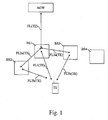
- Fig. 1 is a diagram representing the architecture of the wireless cellular telecommunication network in which the present invention is implemented.
- a server AGW is connected to a plurality of base stations BS1 to BS4 through a telecommunication network.
- the telecommunication network is a dedicated wired network or a public network like a public switched network or an IP based network or a wireless network or an Asynchronous Transfer Mode network or a combination of above cited networks.
- the telecommunication network enables the base stations BS1 to BS4 to be connected together if needed and enables the transfer between the base stations BS of at least a split of a flow of data intended to be transferred to a mobile terminal TE and/or enables the transfer between the base stations BS of at least a split of a flow of data transferred by a mobile terminal TE.
- FIG. 1 only one server AGW is shown, but we can understand that a more important number of servers AGW can be used in the present invention.
- the server AGW In Long Term Evolution (LTE) network currently under discussion in 3GPP, the server AGW is named an Access Gateway, and contains at least one Mobility Management Entity (MME) and one User Plane Entity (UPE). In General Packet Radio Service network, the server AGW is named a Serving GPRS Support Node (SGSN). In mobile IP network, the server AGW is named a Foreign Agent (FA) and in GSM network, the server AGW contains a Visitor Location Register (VLR) and a Mobile Switching Centre (MSC).
- MME Mobility Management Entity
- UPE User Plane Entity
- SGSN Serving GPRS Support Node
- FA Foreign Agent
- VLR Visitor Location Register
- MSC Mobile Switching Centre
- Each base station BS1 to BS4 manages at least one cell not shown in the Fig. 1 .
- a cell of a base station BS is the area in which the signals transferred by the base station BS are received by a mobile terminal TE at a power level which is upper than a predetermined value.
- Fig. 1 only one mobile terminal TE is shown, but we can understand that a more important number of mobile terminals TE are in the wireless cellular telecommunication network.
- Each base station BS may transfer in the cell it manages, a monitoring list comprising information identifying the cells of other base stations BS.
- the mobile terminal TE monitors the signals transferred in these cells and sends measurement reports to the base station BS1 which handles the mobile terminal TE.
- a base station BS handles a mobile terminal TE when the base station BS receives from the server AGW a flow of data to be transferred to the mobile terminal TE and/or transfers to the server AGW a flow of data transferred by the mobile terminal TE.
- the flow of data is transferred from the server AGW to the base station BS which handles the mobile terminal TE.
- the flow of data is transferred from the base station BS which handles the mobile terminal TE to the server AGW. That flow of data is shown by the arrow noted FL(TE).
- the base station BS which handles the mobile terminal TE splits the flow of data to be transferred to the mobile terminal TE in at least two parts.
- a first split is directly transferred by the base station BS which handles the mobile terminal TE to the mobile terminal TE through its wireless interface and at least a second split is transferred by the base station BS which handles the mobile terminal TE to the mobile terminal TE through its network interface and at least a via base station BS.
- the mobile terminal TE receives the at least two splits and reconstructs the flow of data.
- the mobile terminal TE splits the flow of data to be transferred to the base station BS which handles it in at least two parts.
- the base station BS which handles the mobile terminal TE receives at least two splits of a flow of data transferred by the mobile terminal TE.
- a first split is received from the mobile terminal TE directly by the base station BS which handles the mobile terminal TE through its wireless interface and at least a second split is received from the mobile terminal TE by the base station BS which handles the mobile terminals TE through at least a via base station BS.
- the base station BS which handles the mobile terminal TE reconstructs the flow of data.
- the Fig. 1 discloses an example in which the base station BS1 handles the mobile terminal TE.
- the base station BS1 receives a flow of data represented by the arrow FL(TE) to be transferred to the mobile terminal TE.
- the base station BS1 splits the flow of data FL(TE) to be transferred to the mobile terminal TE in three splits.
- a first split represented by the arrow FL1(TE) is directly transferred by the base station BS1 to the mobile terminal TE through its wireless interface.
- a second split represented by the arrow FL2a(TE) is transferred by the base station BS1 to the base station BS2 which transfers, through its wireless interface, the split represented by the arrow FL2b(TE) to the mobile terminal TE.
- a third split represented by the arrow FL3a(TE) is transferred by the base station BS1 to the base station BS3 which transfers, through its wireless interface, the split represented by the arrow FL3b(TE) to the mobile terminal TE.
- the mobile terminal TE receives the three splits and reconstructs the flow of data.
- the mobile terminal TE splits the flow of data to be transferred to the base station BS1 in a first part represented by the arrow FL1(TE), a second part represented by the arrow FL2b(TE) and a third part represented by the arrow FL3b(TE).
- the base station BS2 transfers the received split to the base station BS1 as represented by the arrow FL2a(TE).
- the base station BS3 transfers the received split to the base station BS1 as represented by the arrow FL3a(TE).
- the base station BS1 which handles the mobile terminal TE receives the three splits of the flow of data transferred by the mobile terminal TE.
- the base station BSI reconstructs the flow of data and transfers it to the server 10, as represented by the arrow FL(TE).
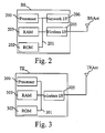
- Fig. 2 is a diagram representing the architecture of a base station according to the present invention.
- Each base station BS has, for example, an architecture based on components connected together by a bus 201 and a processor 200 controlled by the program as disclosed in the Figs. 6 and 7 .
- the bus 201 links the processor 200 to a read only memory ROM 202, a random access memory RAM 203, a network interface 206 and a wireless interface 205.
- the memory 203 contains registers intended to receive variables, information identifying cells like cells which are known as neighbour of the cell or cells of the base station BS, the identifiers of the base stations BS which manage neighbour cells, connection, security information for each communication link with base stations BS which manage neighbour cells and the instructions of the program related to the algorithms as disclosed in the Figs. 6 and 7 .
- the processor 200 controls the operation of the network interface 206 and the wireless interface 205.
- the read only memory 202 contains instructions of the programs related to the algorithms as disclosed in the Figs. 6 and 7 , which are transferred, when the base station BS is powered on to the random access memory 203.
- the base station BS is connected to the telecommunication network through the network interface 206.
- the network interface 206 is a DSL (Digital Subscriber Line) modem, or an ISDN (Integrated Services Digital Network) interface, etc.
- the base station BS exchanges information with the server AGW and the other base stations BS of the wireless cellular telecommunication network.
- the base station BS transfers monitoring lists of information identifying cells and receives, from the mobile terminal TE, measurement reports.
- the wireless interface 205 is connected to one antenna BSant, that is used to collect and radiate radiowaves from/to the mobile terminal TE.
- Fig. 2 only one antenna BSant is shown, but we can understand that a more important number of antennas BSant can be used in the present invention.
- the wireless interface 205 may comprise means for a simultaneous transmission of at least two signals to be transferred to one or plural mobile terminals TE using as example Multiple Input Multiple Output (MIMO) or transmit beamforming techniques or using plural transmission modules working as example in different frequency bands.
- MIMO Multiple Input Multiple Output
- the wireless interface 205 may comprise means for a simultaneous reception of at least two signals transferred by one or plural mobile terminals TE using as example MIMO or receive beamforming techniques or using plural reception modules working as example in different frequency bands.
- Fig. 3 is a diagram representing the architecture of a mobile terminal of the wireless telecommunication system according to the present invention.
- Each mobile terminal TE has, for example, an architecture based on components connected together by a bus 301 and a processor 300 controlled by the program as disclosed in Fig. 8 .
- the bus 301 links the processor 300 to a read only memory ROM 302, a random access memory RAM 303 and a wireless interface 305.
- the memory 303 contains registers intended to receive variables and the instructions of the program related to the algorithm as disclosed in Fig. 8 .
- the read only memory 302 contains instructions of the program related to the algorithm as disclosed in Fig. 8 , which are transferred, when the mobile terminal TE is powered on to the random access memory 303.
- the wireless interface 305 comprises means for detecting, measuring and receiving signals transferred by base stations BS through the downlink channel, and for transmitting measurement reports through the uplink channel of the wireless cellular communication system.
- the wireless interface 305 is connected to one antenna TEAnt, that is used to collect and radiate radiowaves from/to the base stations BS.
- the wireless interface 305 comprises means for simultaneous transmission of at least two signals to be transferred to different base stations BS using as example MIMO or transmit beamforming techniques or using plural transmission modules working as example in different frequency bands.
- the wireless interface 305 may comprise means for a simultaneous reception of at least two signals transferred by different base stations BS using as example MIMO or receive beamforming techniques or using plural reception modules working as example in different frequency bands.
- the wireless interface 305 will be disclosed in more details in reference to the Fig. 5 .
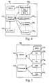
- Fig. 4 is a diagram representing modules comprised in the base station according to the present invention.
- the base station BS comprises a splitter/combiner 410 which splits the flow of data to be transferred to the mobile terminal TE into N plural splits.
- a split comprises data which are different from the one comprised in another split and corresponds to different portions of the data flow. More precisely, the flow of data is decomposed into packets of data, each split is decomposed into different packets of data, each packet of data is marked by the splitter 410 with an information representative of the order of the packet of data in the flow of data.
- the information representative of the order of the packet of data in the flow of data is as example a timestamp or a sequence number.
- the processor 200 of the base station BS executes the tasks of splitting the flow of data and/or combining the splits in place of the splitter/combiner 410.
- the base station BS comprises M X2 tunnels modules 420 I to 420 M for establishing M X2 tunnels which enable the transfer and/or the reception of data with other base stations BS and a S1 tunnel module 450 for establishing a S1 tunnel which can exchange data between the base station BS and the server AGW.
- a X2 tunnel is as the one disclosed in the specification entitled 3GPP TS 36.424 and A S1 tunnel is as the one disclosed in the specification entitled 3GPP TS 36.414.
- each X2 tunnel module 420 Through each X2 tunnel module 420, one split is transferred and/or received.
- the N-M splits which are not transferred and/or received through one X2 tunnel module 420, are each transferred and/or received directly by the base station BS through one radio module 430 of its wireless interface 205 which comprises N-M radio modules 430 M+1 to 430 N .
- Each radio module 430 comprises a transmitter Txb and a receiver Rxb.
- each radio module contains a Radio Link Control (RLC) stack and a Medium Access Control (MAC) stack, responsible for segmenting and scheduling downlink data packets on the transmitter Txb and scheduling transmission grants of uplink data packets to be received by the receiver Rxb, using varying transfer formats Modulation and Coding Scheme (MCS) so as to fit with instantaneous quality of the physical link PHY established with the mobile terminal TE and so as to share the capacity of the wireless channel with other mobile terminals TE having established a radio channel with the base station BS.
- RLC Radio Link Control
- MAC Medium Access Control
- the base station BS comprises a Radio Resource Control RRCb protocol module, which is used to configure the transmission scheme according to the invention by indicating to the Radio Resource Control RRCt protocol module of the mobile terminal TE how data are split.
- RRCb protocol module which is used to configure the transmission scheme according to the invention by indicating to the Radio Resource Control RRCt protocol module of the mobile terminal TE how data are split.
- RRCt protocol module of the mobile terminal TE will be further described in the Fig. 5 .
- the processor 200 of the base station BS executes the tasks of the Radio Resource Control RRCb protocol module.
- the split of data is forwarded to the base station BS which handles the mobile terminal TE through the X2 tunnel 420 established between the base station BS and the base station BS which handles the mobile terminal TE.
- each via base station BS regularly sends quality indicator information to the splitter/combiner 410 through the X2 tunnel.
- the splitter/combiner 410 uses the quality indicator information transferred by each via base station BS to determine, on a per packet basis, through which X2 tunnel each packet of the data flow to be transmitted to the mobile terminal TE should individually be routed, enabling the realisation of different splits with different throughputs.
- the quality indicator information are as example, the achievable throughput of the split of data being delivered by the via base station BS to the mobile terminal TE. It might be derived from the analysis of the capacity or the quality of the radio channel established between the via base station BS and the mobile terminal TE, e.g. derived from Channel Quality Indicators (CQI) reported by the mobile terminal TE to the via base station BS, and/or from the status of FIFO (full, expanding, steady, shrinking, empty) of the via base station BS containing the packets of data of the split received from the base station BS and not yet delivered to the mobile terminal TE, and/or from the load of the cell used by the radio channel established between the via base station BS and the mobile terminal TE.
- CQI Channel Quality Indicators
- Channel Quality Indicators are as example as the ones forwarded in 3GPP/LTE (Third Generation Project/ Long Term Evolution) system by a mobile terminal TE to the base station BS.
- the CQI gives the level of SINR of the pilot signals transmitted by the base station BS and observed by the mobile terminal TE for a given time/frequency position (radio chunk).
- CQI information is typically provided for all radio chunks supported by the radio channel established between the transmitter and the receiver.
- the load of a cell depends on the throughput being delivered on that cell to other mobile terminals TE via other radio channels of the via base station BS.
- Fig. 5 is a diagram representing modules comprised in the wireless interface of a mobile terminal according to the present invention.
- the wireless interface 305 splits the flow of data to be transferred to the base station BS which handles the mobile terminal TE into K independent splits using a splitter 510.
- a split comprises data which are different from the one comprised in another split and corresponds to different portions of the data flow.
- a transmission module Txt basically contains one or more FIFO (First In First Out) buffers.
- FIFO has typically limited size and contains data to be transmitted by transmitter Txt.
- FIFO length is reduced at regular transmission intervals, by the amount of data that is transmitted by the transmission module Txt during that transmission interval. Reciprocally, FIFO length is increased each time the transmitter Tx receives data from the splitter.
- Each transmitter Txt also contains a Radio Link Control RLC not shown in the Fig. 5 , so as to solve any transmission error by means of repetition using an acknowledgment (ARQ), and a Medium Access Control MAC function, so as to minimise any transmission errors due to interference from other transmitters, by means of schedulers, and also means to optimise the transfer format using dynamic Modulation Coding Scheme according to instantaneous link quality of the physical link PHY.
- RLC Radio Link Control
- the transmitter Txt regularly sends quality indicator information to the splitter 510.
- the splitter 510 uses the quality indicator information coming from all the transmitters Txt in order to determine, on a per packet basis, to which transmitter Txt each packet of the flow of data to be transferred to the serving base station BS should individually be routed, enabling the realisation of different splits with different throughputs.
- the quality indicator information consists in the FIFO status (full, expanding, steady, shrinking, empty), in the estimated radio link quality of the physical link PHY, the achievable data rate over the physical link PHY between transmitter Txt and corresponding receiver Rxb of the base station BS which handles the mobile terminal TE or of the via base station BS or is a load indication of the physical link PHY.
- the load indication of the physical link PHY is the throughput being granted by the base station BS with which the physical link PHY is established.
- the wireless interface 305 comprises a combiner 530 which combines the L splits transferred by the base station BS which handles the mobile terminal TE directly or via other base stations BS.
- Each receiver Rxt 540 I to 540 L receives a split from a given transmitter Txb of a base station BS and might exchange with that transmitter Txb some RLC/MAC/PHY control signalling to contribute to the quality of reception of the physical link PHY, e.g. for the purpose of efficient power control, scheduling, MCS or ARQ.
- Each receiver Rxt sends the received data to a combiner 530.
- the combiner 530 collects the data transmitted from the data sources Txb and which are received through various receivers Rxt and generates one single data flow to the destination.
- the wireless interface 305 comprises a Radio Resource Control RRCt protocol module, which is used to configure the transmission scheme according to the invention according to the Radio Resource Control RRCb protocol module of the base station BS which handles the mobile terminal TE.
- RRCt protocol module which is used to configure the transmission scheme according to the invention according to the Radio Resource Control RRCb protocol module of the base station BS which handles the mobile terminal TE.
- K equals L
- the via base stations BS to which the splits of data to be transmitted and forwarded to the base station BS which handles the mobile terminal TE are transmitted are the same as the via base stations BS from which splits of data forwarded to the mobile terminal TE are received.
- the processor 300 of the mobile terminal TE executes the tasks of splitting the flow of data and/or combining the splits in place of the splitter 510 and/or the combiner 530.
- the processor 300 of the mobile terminal TE executes the tasks of the Radio Resource Control RRCt protocol module.
- Fig. 6 is a first algorithm executed by a base station according to the present invention.
- the present algorithm is executed the processor 200 of each base station BS.
- the processor 200 checks if a measurement report is received through the wireless interface 205.
- Each mobile terminal TE regularly measures, or measures on demand, i.e. after a particular event, the quality measurements of the signals transferred in the measurement channels of different base stations BS.
- These measurement reports include information identifying the cells of base stations BS and are reported by the mobile terminal TE to the base station BS which handles the mobile terminal TE.
- the quality measurements give the level of SINR of the pilot signals transmitted by the base station BS and observed by the mobile terminal TE.
- the processor 200 checks if a radio channel has to be added for the mobile terminal TE which sent the measurement report.
- a radio channel has to be added when the quality of the signal transferred by another base station BS is higher than the one transferred by the base station BS which is currently handling the mobile terminal TE or the signals transferred by the base station BS or another base station BS in another cell are upper than a given threshold.
- a radio channel is composed of a downlink and/or uplink channel between the mobile terminal TE and a base station BS.
- step S602. If a radio channel has to be added for the mobile terminal TE which sent the measurement report, the processor 200 moves to step S602. Otherwise, the processor 200 moves to step S620.
- the processor 200 checks if the radio channel has to be setup in a cell controlled by another base station BS.
- the processor 200 moves to step S603. Otherwise, the processor 200 moves to step S610.
- the processor 200 commands the transfer of a X2 tunnel setup request message to the other base station BS.
- the X2 tunnel setup request message requests the other base station BS to establish link or a user plane interface (X2 tunnel) with the base station BS which handles the mobile terminal TE and to establish in the cell of the other base station BS another radio channel (RLC/MAC/PHY) between the other base station BS and the mobile terminal TE.
- X2 tunnel link or a user plane interface
- RLC/MAC/PHY radio channel
- the processor 200 detects the reception, through the network interface 206, of channel information determined by the other base station BS.
- the channel information are at least the identifier C-RNTI (Cell Radio Network Temporary Identity) of the mobile terminal TE in the cell of the other base station BS and information identifying the radio channel to be setup.
- C-RNTI Cell Radio Network Temporary Identity
- the processor 200 commands the transfer of a channel setup message to the mobile terminal TE.
- the channel setup message comprises the C-RNTI and information identifying the radio channel to be setup received at step S604 and an identifier of a cell.
- a new radio channel is established between the other base station BS and the mobile terminal TE.
- the information identifying the setup radio channel includes the duplex mode and/or the frequency bands used for the transfer of signals in the uplink and downlink channels and/or the codes or the timeslots used for the transfer of signals in the uplink and downlink signals from/to the mobile terminal TE.
- the processor 200 commands the splitter/combiner 410 to split the flow of data to be transferred to the mobile terminal TE in at least two parts.
- a first split is transferred to the mobile terminal TE directly through its wireless interface 205 by the base station BS which handles the mobile terminal TE and a second split is transferred to the mobile terminal TE by the base station BS which handles the mobile terminal TE through the other base station BS which transferred signals on which quality measurement was correct.
- the other base station BS is then a via base station BS.
- the mobile terminal TE receives the at least two splits and reconstructs the flow of data.
- the processor 200 commands the splitter/combiner 410 to start the reconstruction of the data flow transmitted to the base station BS from at least two received splits of a flow of data transferred by the mobile terminal TE.
- a first split is received from the mobile terminal TE directly by the base station BS which handles the mobile tenninal TE and a second split is received from the mobile terminal TE by the base station BS which handles the mobile terminal TE through the via base station BS.
- the base station BS which handles the mobile terminal TE reconstructs the flow of data and transfers it to the server AGW.
- the processor 200 determines the channel information for the new radio channel to be setup in a cell of the base station BS which handles the mobile terminal TE.
- the channel information are at least the identifier C-RNTI of the mobile terminal TE in the cell of the base station BS and information identifying the radio channel to be setup.
- the processor 200 commands the transfer of a channel setup message to the mobile terminal TE.
- the channel setup message comprises the C-RNTI, an identifier of a cell and information identifying the radio channel to be setup.
- the base station BS and the mobile terminal TE establish a new radio channel.
- the processor 200 commands the splitter/combiner 410 to split the flow of data to be transferred to the mobile terminal TE in at least two parts. At least one split is directly transferred by the base station BS which handles the mobile terminal TE through the radio channel established between the base station BS and the mobile terminal TE.
- the processor 200 commands the splitter/combiner 410 to start the reconstruction of the flow of data transmitted to the base station BS by the mobile terminal TE from at least two received splits of a flow of data transferred by the mobile terminal TE. At least one split is directly received from the mobile terminal TE by the base station BS which handles the mobile terminal TE through the radio channel established between the base station BS and the mobile terminal TE.
- the processor 200 checks if a radio channel should be removed for the mobile terminal TE which sent the measurement report.
- a radio channel should be removed if, for an already established radio channel between one base station BS and the mobile terminal TE, the quality of measurement of the signal transferred by the base station BS is lower than a given threshold.
- the radio channel that should be removed is a radio channel established between the terminal and the base station BS which handles the mobile terminal TE or a radio channel established between the terminal and a base station BS which doesn't handle the mobile terminal TE.
- step S621 If a radio channel should be removed for the mobile terminal TE which sent the measurement report, the processor 200 moves to step S621. Otherwise, the processor 200 returns to step S600.
- the processor 200 commands the transfer of a channel release message to the mobile terminal TE.
- the channel release message comprises the identifier of the cell of the base station BS which transferred signal for which the quality of the measurement is lower than the given threshold.
- the processor 200 receives, from the mobile terminal TE a channel release confirmation message.
- the processor 200 checks if the radio channel has to be released in a cell of another base station BS.
- the processor 200 moves to step S630. Otherwise, the processor 200 moves to step S624.
- the processor 200 commands the splitter/combiner 410 to decrement the number of splits of the flow of data to be transferred to the mobile terminal TE and to stop to split the flow of data on the radio channel to be released.
- the processor 200 commands the splitter/combiner 410 to stop to use data packets received from the released radio channel for the reconstruction of the flow of data transferred by the mobile terminal TE.
- the processor 200 commands the splitter/combiner 410 to stop to split the flow of data in a split to be transferred in the X2 tunnel between the base station BS which handles the mobile terminal TE and the other base station BS which transferred signal for which the quality of the measurement is lower than the given threshold.
- the processor 200 commands the transfer of a channel remove request message to the other BS which transferred signal for which the quality of the measurement is lower than a given threshold.
- the other base station BS releases the radio channel (RLC/MAC/PHY) between the other base station BS and the mobile terminal TE in the cell of the other base station BS.
- the other base station BS releases the X2 tunnel between the base station BS which handles the mobile terminal TE and the other base station BS which transferred signal for which the quality of the measurement is lower than the given threshold.
- the processor 200 commands the splitter/combiner 410 to stop to use data packets received through the released X2 tunnel for the reconstruction of the flow of data transferred by the mobile terminal TE.
- the base station BS which handles the mobile terminal TE transfers the flow of data to the server AGW.
- the processor 200 checks if a X2 tunnel setup request message is received from another base station BS which handles another mobile terminal TE.
- step S64 If a X2 tunnel setup request message is received from another base station BS, the processor 200 moves to step S641. Otherwise, the processor 200 moves to step S650.
- the processor 200 establishes a X2 tunnel with the other base station BS which handles the other mobile terminal TE.
- the processor 200 establishes a radio channel (RLC and MAC stacks, Txt and Rxt modules) between the base station BS and the other mobile terminal TE in the cell of the base station BS identified in the received X2 tunnel setup request message.
- RLC and MAC stacks, Txt and Rxt modules a radio channel between the base station BS and the other mobile terminal TE in the cell of the base station BS identified in the received X2 tunnel setup request message.
- the processor 200 determines channel information associated to the established radio channel.
- the channel information are at least the identifier C-RNTI of the other mobile terminal TE in the cell of the base station BS and information identifying the setup radio channel.
- the channel information associated to the established radio channel also includes the duplex mode and/or the frequency bands used for uplink and downlink signals and/or the codes or the timeslots used for the transfer of uplink and downlink signals from/to the other mobile terminal TE.
- the processor 200 commands the transfer of the determined channel information to the other base station BS which handles the other mobile terminal TE.
- the processor 200 checks if a X2 tunnel release request message is received from another base station BS which handles another mobile terminal TE.
- step S651 If a X2 tunnel release request message is received from another base station BS, the processor 200 moves to step S651. Otherwise, the processor 200 returns to step S600.
- the processor 200 checks if some packets transferred to the other mobile terminal TE through the radio channel between the base station BS and the other mobile terminal TE have not yet been acknowledged by the other mobile terminal TE.
- step S652 If some packets have not yet been acknowledged by the other mobile terminal TE, the processor 200 moves to step S652. Otherwise, the processor 200 moves to step S653.
- the processor 200 commands the transfer of the not acknowledged packets to the other base station BS through the X2 tunnel established with the other base station BS together with an indication of no transmission.
- the processor 200 commands the release of the user plane interface (X2 tunnel) with the other base station BS which handles the other mobile terminal TE.
- the processor 200 releases the radio channel (RLC and MAC stacks, Txb and Rxb modules) between the base station BS and the other mobile terminal TE in the cell of the base station BS.
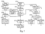
- Fig. 7 is a second algorithm executed by a base station according to the present invention.
- the present algorithm is executed by the processor 200 of each base station BS in parallel with the algorithm disclosed in reference to the Fig. 6 .
- the processor 200 checks if a packet transferred through a radio channel established between the base station BS and a mobile terminal TE is received by the base station BS.
- step S701 If a packet transferred through a radio channel established between the base station BS and a mobile terminal TE is received by the base station BS, the processor 200 moves to step S701. Otherwise, the processor 200 moves to step S710.
- the processor 200 commands the transfer of an acknowledgment of the received packet through the wireless interface 205.
- the processor 200 checks if the base station BS handles the mobile terminal TE which transferred the received packet.
- the processor 200 commands the transfer of the packet received at step S700 to the base station BS which handles the mobile terminal TE through the X2 tunnel established with the base station BS which handles the mobile terminal TE.
- the processor 200 checks if a packet is received through a X2 tunnel.
- step S711 If a packet is received through a X2 tunnel, the processor 200 moves to step S711. Otherwise, the processor 200 moves to step S720.
- the processor 200 checks if the base station BS handles the mobile terminal TE.
- step S712 If the base station BS handles the mobile terminal TE, the processor 200 moves to step S712. Otherwise, the processor 200 moves to step S713.
- the processor 200 commands the transfer of the received packet to the mobile terminal TE through the radio channel established between the base station BS and the mobile terminal TE.
- the processor 200 checks if the received packet is a packet sent back by another base station BS as disclosed at step S652 of the Fig. 6 .
- a packet which is sent back comes together with an indication of no transmission.
- the processor 200 commands the splitter/combiner 410 to reconstruct the flow of data transferred to the base station BS from at least two received splits of a flow of data transferred by the mobile terminal TE.
- a first split is received from the mobile terminal TE directly by the base station BS which handles the mobile terminal TE and a second split is received from the mobile terminal TE by the base station BS which handles the mobile terminal TE through the other base station BS named via base station BS.
- the base station BS which handles the mobile terminal TE reconstructs the flow of data and transfers it to the server AGW at step S716 through a link named S1 tunnel.
- the processor 200 checks if a packet of data is received from the server AGW.
- step S72 If data are received from the server AGW, the processor 200 moves to step S721. Otherwise, the processor 200 returns to step S700.
- the processor 200 commands the splitter/combiner 410 to determine in which path the packet has to be transferred, among the radio channel established between the base station BS and the mobile terminal TE and the X2 tunnels established with other base station or stations BS having established a radio channel with the mobile terminal TE.
- the splitter/combiner 410 uses the quality indicator information like the quality indicator information coming from all the FIFO under its control to determine, on a per packet base, to which path the packet has to be transferred.
- the processor 200 checks if the splitter/combiner 410 has determined that the packet has to be transferred through a X2 tunnel.
- step S724 If the splitter/combiner 410 has determined that the packet has to be transferred through a X2 tunnel, the processor 200 moves to step S724. Otherwise, the processor 200 moves to step S723.
- the processor 200 commands the transfer of the packet through the radio channel established between the base station BS and the mobile terminal TE.
- the processor 200 commands the transfer of the packet through the X2 tunnel identified at step S721.
- Fig. 8 is an example of an algorithm executed by a mobile terminal according to the present invention.
- the present algorithm is executed by the processor 300 of each mobile terminal TE.
- the processor 300 commands the transfer of a measurement report to the base station BS which handles it.
- Each mobile terminal TE regularly measures, or measures on demand, i.e. after a particular event, the quality measurements of the signals transferred in the measurement channels of different base stations BS.
- These measurement reports include information identifying the cells of the base stations BS and are reported by the mobile terminal TE to the base station BS which is currently handling the mobile terminal TE.
- the mobile terminal TE always transfers the measurement report to the base station BS which handles it through one radio channel established with the base station BS which handles it.
- the mobile terminal TE transfers the measurement report to the base station BS which handles it through the radio channel having the highest quality among the radio channels the mobile terminal TE has established with any base stations BS.
- the quality measurements typically give the level of SINR of the pilot signals transmitted by the base stations BS and observed by the mobile terminal TE.
- the processor 300 checks if a channel setup message is received through the wireless interface 305.
- the channel setup message comprises a C-RNTI, an identifier of a cell and information identifying the radio channel being setup.
- the channel information associated to the radio channel being setup also includes the duplex mode and/or the frequency bands used for uplink and downlink signals and/or the codes or the timeslots used for the transfer of uplink and downlink signals from/to the mobile terminal TE.
- the channel setup message is preferably transferred by the base station BS which handles the mobile terminal TE.
- the channel setup message may also be transferred by another base station BS with which a radio channel has been setup.
- step S802 If a channel setup message is received, the processor 300 moves to step S802. Otherwise, the processor 300 moves to step S810.
- the processor 300 establishes a new radio channel in the cell identified in the channel setup message and uses the C-RNTI comprised in the received message and information identifying the radio channel to be setup.
- the processor 300 commands the splitter 510 to split the flow of data to be transferred to the base station BS which handles the mobile terminal TE in at least two parts.
- a first split is directly transferred to the base station BS which handles the mobile terminal TE and a second split is transferred to the base station BS which handles the mobile terminal TE through the other base station BS with which the radio channel has been setup at step S802.
- the processor 300 commands the combiner 530 to start the reconstruction of the data flow transmitted to the mobile terminal TE from at least two received splits of a flow of data received by the mobile terminal TE.
- a first split is directly received by the mobile terminal TE from the base station BS which handles the mobile terminal TE and a second split is received by the mobile terminal TE from the base station BS which handles the mobile terminal TE through the other base station BS with which the radio channel has been setup at step S802.
- the processor 300 commands the transfer of a channel setup confirmation message to the base station BS which handles the mobile terminal TE.
- the mobile terminal TE always transfers the channel setup confirmation message to the base station BS which handles it trough one radio channel established with the base station BS which handles it.
- the mobile terminal TE transfers the channel setup confirmation to the base station BS which handles it through the radio channel having the highest quality among the radio channels the mobile terminal TE has established with any base stations BS.
- the mobile terminal TE transfers the channel setup confirmation to the base station BS which handles it through the radio channel established at step S802.
- the processor 300 checks if a channel remove message is received through the wireless interface 305.
- the channel setup message comprises a C-RNTI, an identifier of a cell and information identifying the radio channel to be released.
- step S811 If a channel remove message is received, the processor 300 moves to step S811. Otherwise, the processor 300 moves to step S820.
- the processor 300 commands the splitter 510 to stop to split the flow of data in the part to be transferred through the radio channel to be released.
- the processor 300 checks if some packets transferred by the mobile terminal TE through the radio channel to be deleted have not yet been acknowledged by the base station BS with which the radio channel has to be deleted.
- the processor 300 selects another radio channel, as example the radio channel between the mobile terminal TE and the base station BS which handles the mobile terminal TE.
- the processor 300 commands the transfer of the not acknowledged packets to the base station BS which handles the mobile terminal TE through the radio channel selected at step S813.
- the processor 300 commands the release of the radio channel (RLC and MAC stacks, Txt and Rxt modules).
- the processor 300 commands the combiner 530 to stop to use data packets received through the released radio channel for the reconstruction of the flow of data transmitted to the mobile terminal TE.
- the processor 300 checks if a data packet has to be transferred to the base station BS which handles the mobile terminal TE.
- step S82 If a data packet has to be transferred, the processor 300 moves to step S821. Otherwise, the processor 300 moves to step S830.
- the processor 300 commands the splitter 510 in order to select one radio channel through which the packet has to be transferred.
- the splitter 510 uses the quality indicator information like the one coming from all the FIFO under its control to determine, on a per packet basis, through which radio channel the packet has to be transferred.
- the splitter 510 selects the radio channel with best quality indicator information having a FIFO length below a given threshold.
- the packet is transferred to the transmitter Txt handling the transmission of signal to the base station BS which handles the mobile terminal TE through the selected radio channel.
- the length of the corresponding FIFO is incremented by the size of the data packet.
- the length of the corresponding FIFO is decremented by the size of the data packet.
- the processor 300 checks if a packet is received through the wireless interface 305.
- step S830 If a packet is received at step S830, the processor moves to step S831. Otherwise, the processor 300 returns to step S800.
- the processor 300 commands the transfer of an acknowledgment of the received packet to the base station BS with which the radio channel on which the packet has been received is established.
- the processor 300 commands the combiner 530 to reconstruct the flow of data using the received packet.
Landscapes
- Engineering & Computer Science (AREA)
- Computer Networks & Wireless Communication (AREA)
- Signal Processing (AREA)
- Quality & Reliability (AREA)
- Mobile Radio Communication Systems (AREA)
Priority Applications (4)
| Application Number | Priority Date | Filing Date | Title |
|---|---|---|---|
| EP08006221.9A EP2107731B1 (de) | 2008-03-31 | 2008-03-31 | Verfahren und Vorrichtung zur Übertragung eines Datenflusses über eine erste Telekommunikationsvorrichtung an eine zweite Telekommunikationsvorrichtung |
| US12/407,168 US8284717B2 (en) | 2008-03-31 | 2009-03-19 | Method and a device for transferring a flow of data by a first telecommunication device to a second telecommunication device |
| JP2009075455A JP5537056B2 (ja) | 2008-03-31 | 2009-03-26 | データフローを転送する方法および装置、データフローを受信する方法、データフローを受信する通信装置、ならびにコンピュータプログラム |
| CN200910141957.7A CN101568142B (zh) | 2008-03-31 | 2009-03-30 | 由第一电信设备向第二电信设备传送数据流的方法和设备 |
Applications Claiming Priority (1)
| Application Number | Priority Date | Filing Date | Title |
|---|---|---|---|
| EP08006221.9A EP2107731B1 (de) | 2008-03-31 | 2008-03-31 | Verfahren und Vorrichtung zur Übertragung eines Datenflusses über eine erste Telekommunikationsvorrichtung an eine zweite Telekommunikationsvorrichtung |
Publications (2)
| Publication Number | Publication Date |
|---|---|
| EP2107731A1 true EP2107731A1 (de) | 2009-10-07 |
| EP2107731B1 EP2107731B1 (de) | 2016-11-09 |
Family
ID=39607475
Family Applications (1)
| Application Number | Title | Priority Date | Filing Date |
|---|---|---|---|
| EP08006221.9A Active EP2107731B1 (de) | 2008-03-31 | 2008-03-31 | Verfahren und Vorrichtung zur Übertragung eines Datenflusses über eine erste Telekommunikationsvorrichtung an eine zweite Telekommunikationsvorrichtung |
Country Status (4)
| Country | Link |
|---|---|
| US (1) | US8284717B2 (de) |
| EP (1) | EP2107731B1 (de) |
| JP (1) | JP5537056B2 (de) |
| CN (1) | CN101568142B (de) |
Cited By (2)
| Publication number | Priority date | Publication date | Assignee | Title |
|---|---|---|---|---|
| EP2503741A1 (de) * | 2009-11-18 | 2012-09-26 | Nec Corporation | Dynamisches routenverzweigungssystem und dynamisches routenverzweigungsverfahren |
| EP3346764A1 (de) * | 2017-01-05 | 2018-07-11 | Panasonic Intellectual Property Corporation of America | Verfahren und vorrichtungen für die auswahl einer funkverbindung in einem mobilen kommunikationssystem |
Families Citing this family (24)
| Publication number | Priority date | Publication date | Assignee | Title |
|---|---|---|---|---|
| KR101480929B1 (ko) * | 2010-02-12 | 2015-01-12 | 인터디지탈 테크날러지 코포레이션 | 다중 사이트 간의 데이터 분할 |
| CN102238609B (zh) | 2010-04-28 | 2016-08-17 | 北京三星通信技术研究有限公司 | X2接口建立方法和移动通信系统中小区切换方法 |
| US9295089B2 (en) * | 2010-09-07 | 2016-03-22 | Interdigital Patent Holdings, Inc. | Bandwidth management, aggregation and internet protocol flow mobility across multiple-access technologies |
| US20120120890A1 (en) * | 2010-11-12 | 2012-05-17 | Electronics And Telecommunications Research Institute | Apparatus and method for transmitting multimedia data in multimedia service providing system |
| FI3319395T3 (fi) | 2010-12-03 | 2023-08-01 | Interdigital Patent Holdings Inc | Menetelmä ja laite moniradioliityntätekniikan kantoaaltojen yhdistämisen suorittamiseksi |
| IL210169A0 (en) | 2010-12-22 | 2011-03-31 | Yehuda Binder | System and method for routing-based internet security |
| US9172597B2 (en) * | 2011-04-28 | 2015-10-27 | Invensys Systems, Inc. | Data combiner and splitter |
| US20130088960A1 (en) | 2011-10-07 | 2013-04-11 | Futurewei Technologies, Inc. | System and Method for Information Delivery with Multiple Point Transmission |
| US9838089B2 (en) | 2011-10-07 | 2017-12-05 | Futurewei Technologies, Inc. | System and method for multiple point transmission in a communications system |
| US9807644B2 (en) | 2012-02-17 | 2017-10-31 | Interdigital Patent Holdings, Inc. | Hierarchical traffic differentiation to handle congestion and/or manage user quality of experience |
| US9585054B2 (en) | 2012-07-19 | 2017-02-28 | Interdigital Patent Holdings, Inc. | Method and apparatus for detecting and managing user plane congestion |
| CN103828456B (zh) * | 2012-08-17 | 2018-07-13 | 华为技术有限公司 | 数据发送方法和装置 |
| KR101860811B1 (ko) | 2012-08-23 | 2018-05-24 | 인터디지탈 패튼 홀딩스, 인크 | 무선 시스템에서의 다중 스케줄러들을 이용한 동작 |
| WO2014110410A1 (en) | 2013-01-11 | 2014-07-17 | Interdigital Patent Holdings, Inc. | User-plane congestion management |
| WO2014172892A1 (zh) * | 2013-04-26 | 2014-10-30 | 华为技术有限公司 | 业务分流方法、装置及系统 |
| US9730271B2 (en) * | 2013-06-03 | 2017-08-08 | Avago Technologies General Ip (Singapore) Pte. Ltd. | Systems and methods for splitting and recombining communications in multi-network environments |
| CN104378777B (zh) | 2013-08-13 | 2020-12-22 | 索尼公司 | 无线通信系统中的用户设备、基站设备、通信设备和方法 |
| US20150089382A1 (en) * | 2013-09-26 | 2015-03-26 | Wu-chi Feng | Application context migration framework and protocol |
| US9628459B2 (en) * | 2014-03-18 | 2017-04-18 | Ca, Inc. | Secure data transmission using multi-channel communication |
| CN105451355B (zh) * | 2014-08-18 | 2019-06-18 | 上海诺基亚贝尔股份有限公司 | 用于向自身服务的用户设备传输数据的方法、基站和系统 |
| WO2017167369A1 (en) * | 2016-03-31 | 2017-10-05 | Huawei Technologies Co., Ltd. | An apparatus and method for controlling the secure transmission of a message from a transmitter to a receiver |
| US10341225B2 (en) * | 2016-12-30 | 2019-07-02 | Hughes Network Systems, Llc | Bonding of satellite terminals |
| US10341927B2 (en) * | 2017-07-20 | 2019-07-02 | GM Global Technology Operations LLC | Vehicle wireless unit and method of operating the same |
| CN107454638A (zh) * | 2017-08-02 | 2017-12-08 | 杭州迪普科技股份有限公司 | 报文的发送方法及装置、计算机可读存储介质 |
Citations (3)
| Publication number | Priority date | Publication date | Assignee | Title |
|---|---|---|---|---|
| WO2002052787A2 (en) | 2000-12-22 | 2002-07-04 | The Charles Stark Draper Laboratory, Inc. | Message splitting and spatially diversified message routing for increasing transmission assurance and data security over distributed networks |
| DE102004049705A1 (de) | 2004-10-12 | 2006-04-20 | Siemens Ag | Verfahren zum optimalen Betrieb eines eng gekoppelten Funknetzwerks mit verschiedenen Netzwerktechnologien und eine entsprechende Vorrichtung für ein Netzelement |
| EP1873929A1 (de) | 2006-06-30 | 2008-01-02 | Siemens Aktiengesellschaft | Verfahren zum Übertragen von Daten in einem Kommunikationssystem, Kommunikationssystem und Endgerät |
Family Cites Families (9)
| Publication number | Priority date | Publication date | Assignee | Title |
|---|---|---|---|---|
| EP1514385A1 (de) * | 2002-05-31 | 2005-03-16 | Nokia Corporation | Endgerät, basisstation und verfahren für ein zellulares netzwerk |
| EP1854235B1 (de) * | 2005-02-17 | 2014-04-09 | Telefonaktiebolaget LM Ericsson (publ) | Verfahren und anordnung zur kooperativen weiterleitung |
| EP1727297A1 (de) * | 2005-05-25 | 2006-11-29 | Siemens Aktiengesellschaft | Verfahren und Endgerät zur Interferenzreduzierung in einem Funkkommunikationssystem |
| EP2276299B1 (de) * | 2006-03-20 | 2017-08-16 | Mitsubishi Electric R&D Centre Europe B.V. | Zellulares Kommunikationsnetz zur Bestimmung einer Lokalisierungszone |
| JP4802804B2 (ja) * | 2006-03-27 | 2011-10-26 | 日本電気株式会社 | 移動体通信システムにおけるデータ伝送方法およびシステム |
| EP1892978B1 (de) * | 2006-08-22 | 2019-01-02 | Mitsubishi Electric R&D Centre Europe B.V. | Verfahren und Vorrichtung zum Herstellen von Multimedia-Inhalten-Übertragung in einer Zelle eines Funktelekommunikationsnetzwerks |
| GB0616682D0 (en) * | 2006-08-22 | 2006-10-04 | Nec Corp | Mobile telecommunications |
| JP4838181B2 (ja) * | 2007-03-19 | 2011-12-14 | 株式会社エヌ・ティ・ティ・ドコモ | ハンドオーバ方法及び無線基地局 |
| US7940718B2 (en) * | 2008-03-11 | 2011-05-10 | Telefonaktiebolaget L M Ericsson (Publ) | Trace log management in a mobile communication system |
-
2008
- 2008-03-31 EP EP08006221.9A patent/EP2107731B1/de active Active
-
2009
- 2009-03-19 US US12/407,168 patent/US8284717B2/en active Active
- 2009-03-26 JP JP2009075455A patent/JP5537056B2/ja active Active
- 2009-03-30 CN CN200910141957.7A patent/CN101568142B/zh active Active
Patent Citations (3)
| Publication number | Priority date | Publication date | Assignee | Title |
|---|---|---|---|---|
| WO2002052787A2 (en) | 2000-12-22 | 2002-07-04 | The Charles Stark Draper Laboratory, Inc. | Message splitting and spatially diversified message routing for increasing transmission assurance and data security over distributed networks |
| DE102004049705A1 (de) | 2004-10-12 | 2006-04-20 | Siemens Ag | Verfahren zum optimalen Betrieb eines eng gekoppelten Funknetzwerks mit verschiedenen Netzwerktechnologien und eine entsprechende Vorrichtung für ein Netzelement |
| EP1873929A1 (de) | 2006-06-30 | 2008-01-02 | Siemens Aktiengesellschaft | Verfahren zum Übertragen von Daten in einem Kommunikationssystem, Kommunikationssystem und Endgerät |
Non-Patent Citations (1)
| Title |
|---|
| PHATAK D S ET AL: "A novel mechanism for data streaming across multiple IP links for improving throughput and reliability in mobile environments", PROCEEDINGS IEEE INFOCOM 2002. THE CONFERENCE ON COMPUTER COMMUNICATIONS. 21ST. ANNUAL JOINT CONFERENCE OF THE IEEE COMPUTER AND COMMUNICATIONS SOCIETIES. NEW YORK, NY, JUNE 23 - 27, 2002; [PROCEEDINGS IEEE INFOCOM. THE CONFERENCE ON COMPUTER COMMUNI, vol. 2, 23 June 2002 (2002-06-23), pages 773 - 781, XP010593639, ISBN: 978-0-7803-7476-8 * |
Cited By (7)
| Publication number | Priority date | Publication date | Assignee | Title |
|---|---|---|---|---|
| EP2503741A1 (de) * | 2009-11-18 | 2012-09-26 | Nec Corporation | Dynamisches routenverzweigungssystem und dynamisches routenverzweigungsverfahren |
| EP2503741A4 (de) * | 2009-11-18 | 2013-05-22 | Nec Corp | Dynamisches routenverzweigungssystem und dynamisches routenverzweigungsverfahren |
| US9001656B2 (en) | 2009-11-18 | 2015-04-07 | Nec Corporation | Dynamic route branching system and dynamic route branching method |
| US9385937B2 (en) | 2009-11-18 | 2016-07-05 | Nec Corporation | Dynamic route branching system and dynamic route branching method |
| EP3346764A1 (de) * | 2017-01-05 | 2018-07-11 | Panasonic Intellectual Property Corporation of America | Verfahren und vorrichtungen für die auswahl einer funkverbindung in einem mobilen kommunikationssystem |
| WO2018127322A1 (en) * | 2017-01-05 | 2018-07-12 | Panasonic Intellectual Property Corporation Of America | Methods and apparatuses for selecting a radio link in a mobile communication system |
| US11356942B2 (en) | 2017-01-05 | 2022-06-07 | Panasonic Intellectual Property Corporation Of America | Methods and apparatuses for selecting a radio link in a mobile communication system |
Also Published As
| Publication number | Publication date |
|---|---|
| CN101568142A (zh) | 2009-10-28 |
| EP2107731B1 (de) | 2016-11-09 |
| JP5537056B2 (ja) | 2014-07-02 |
| JP2009246966A (ja) | 2009-10-22 |
| US20090253433A1 (en) | 2009-10-08 |
| US8284717B2 (en) | 2012-10-09 |
| CN101568142B (zh) | 2014-12-31 |
Similar Documents
| Publication | Publication Date | Title |
|---|---|---|
| EP2107731B1 (de) | Verfahren und Vorrichtung zur Übertragung eines Datenflusses über eine erste Telekommunikationsvorrichtung an eine zweite Telekommunikationsvorrichtung | |
| US11356924B2 (en) | Radio communication system, base station, mobile station, communication control method, and computer readable medium | |
| EP2974490B1 (de) | Gemeinsame koordinierte mehrpunktübertragung mit reduzierten backhaul-anforderungen | |
| KR102664930B1 (ko) | 이동통신 시스템에서 셀 측정 정보를 수집하고 보고하는 방법 및 장치 | |
| US9549353B2 (en) | Wireless device and method of transmitting uplink data and buffer status reports in a wireless communications system | |
| KR101288770B1 (ko) | 부하 분산을 위한 기지국들 간 자원 상태 정보의 시그널링 | |
| EP2906009B1 (de) | Drahtloses kommunikationssystem, basisstation und kommunikationssteuerungsverfahren | |
| JP6065841B2 (ja) | 無線局、及び無線局によるユーザーデータの処理方法 | |
| JP6394734B2 (ja) | 基地局で使用されるノード及びその方法 | |
| US20030031119A1 (en) | Method and apparatus for transmitting user data in an HSDPA mobile communication system | |
| EP2785138B1 (de) | Drahtlose station und verfahren zur verarbeitung von daten mit der drahtlosen station | |
| US20090323639A1 (en) | Fast serving cell change method and apparatus for mobile communication system | |
| US9313705B2 (en) | Data relay apparatus for transferring data to a mobile terminal via a plurality of base stations | |
| WO2022005346A1 (en) | Method for scheduling multiple replicated data flows over a number of wireless transmission paths | |
| KR20210125377A (ko) | 차세대 이동 통신 시스템에서 무선 링크 실패 정보를 저장 및 보고하는 방법 및 장치 | |
| JP5452046B2 (ja) | 複数の資源のうちのいずれの資源に、一群の要素のうちの複数の要素を配分しなくてはならないかを決定する方法及び装置、並びにコンピュータプログラム | |
| EP2426829A1 (de) | Verfahren für den Betrieb einer Basisstation in einem drahtlosen Kommunikationsnetzwerk und Basisstation eines drahtlosen Kommunikationsnetzwerks | |
| WO2019182500A1 (en) | First unit, distributed unit and methods for adapting a transmission rate in a wireless communication network | |
| EP2107696A1 (de) | Verfahren und Vorrichtung zur Verwaltung einer Reihe von Basisstationen eines drahtlosen zellularen Telekommunikationsnetzwerks | |
| KR20220152861A (ko) | 무선 통신 시스템에서 위치 추정 서비스를 제공하기 위한 방법 및 장치 |
Legal Events
| Date | Code | Title | Description |
|---|---|---|---|
| PUAI | Public reference made under article 153(3) epc to a published international application that has entered the european phase |
Free format text: ORIGINAL CODE: 0009012 |
|
| AK | Designated contracting states |
Kind code of ref document: A1 Designated state(s): AT BE BG CH CY CZ DE DK EE ES FI FR GB GR HR HU IE IS IT LI LT LU LV MC MT NL NO PL PT RO SE SI SK TR |
|
| AX | Request for extension of the european patent |
Extension state: AL BA MK RS |
|
| 17P | Request for examination filed |
Effective date: 20091222 |
|
| 17Q | First examination report despatched |
Effective date: 20100122 |
|
| AKX | Designation fees paid |
Designated state(s): AT BE BG CH CY CZ DE DK EE ES FI FR GB GR HR HU IE IS IT LI LT LU LV MC MT NL NO PL PT RO SE SI SK TR |
|
| REG | Reference to a national code |
Ref country code: DE Ref legal event code: R079 Ref document number: 602008047235 Country of ref document: DE Free format text: PREVIOUS MAIN CLASS: H04L0012560000 Ipc: H04L0001000000 |
|
| GRAP | Despatch of communication of intention to grant a patent |
Free format text: ORIGINAL CODE: EPIDOSNIGR1 |
|
| RIC1 | Information provided on ipc code assigned before grant |
Ipc: H04W 40/22 20090101ALI20160525BHEP Ipc: H04L 1/00 20060101AFI20160525BHEP Ipc: H04L 12/721 20130101ALI20160525BHEP Ipc: H04L 12/707 20130101ALI20160525BHEP Ipc: H04W 40/12 20090101ALN20160525BHEP |
|
| RIC1 | Information provided on ipc code assigned before grant |
Ipc: H04L 1/00 20060101AFI20160530BHEP Ipc: H04L 12/721 20130101ALI20160530BHEP Ipc: H04L 12/707 20130101ALI20160530BHEP Ipc: H04W 40/22 20090101ALI20160530BHEP Ipc: H04W 40/12 20090101ALN20160530BHEP |
|
| INTG | Intention to grant announced |
Effective date: 20160615 |
|
| RIC1 | Information provided on ipc code assigned before grant |
Ipc: H04L 1/00 20060101AFI20160606BHEP Ipc: H04W 40/12 20090101ALN20160606BHEP Ipc: H04L 12/707 20130101ALI20160606BHEP Ipc: H04W 40/22 20090101ALI20160606BHEP Ipc: H04L 12/721 20130101ALI20160606BHEP |
|
| GRAS | Grant fee paid |
Free format text: ORIGINAL CODE: EPIDOSNIGR3 |
|
| GRAA | (expected) grant |
Free format text: ORIGINAL CODE: 0009210 |
|
| AK | Designated contracting states |
Kind code of ref document: B1 Designated state(s): AT BE BG CH CY CZ DE DK EE ES FI FR GB GR HR HU IE IS IT LI LT LU LV MC MT NL NO PL PT RO SE SI SK TR |
|
| REG | Reference to a national code |
Ref country code: GB Ref legal event code: FG4D |
|
| REG | Reference to a national code |
Ref country code: AT Ref legal event code: REF Ref document number: 844787 Country of ref document: AT Kind code of ref document: T Effective date: 20161115 Ref country code: CH Ref legal event code: EP |
|
| REG | Reference to a national code |
Ref country code: IE Ref legal event code: FG4D |
|
| REG | Reference to a national code |
Ref country code: DE Ref legal event code: R096 Ref document number: 602008047235 Country of ref document: DE |
|
| PG25 | Lapsed in a contracting state [announced via postgrant information from national office to epo] |
Ref country code: LV Free format text: LAPSE BECAUSE OF FAILURE TO SUBMIT A TRANSLATION OF THE DESCRIPTION OR TO PAY THE FEE WITHIN THE PRESCRIBED TIME-LIMIT Effective date: 20161109 |
|
| REG | Reference to a national code |
Ref country code: LT Ref legal event code: MG4D |
|
| REG | Reference to a national code |
Ref country code: NL Ref legal event code: MP Effective date: 20161109 |
|
| REG | Reference to a national code |
Ref country code: FR Ref legal event code: PLFP Year of fee payment: 10 |
|
| REG | Reference to a national code |
Ref country code: AT Ref legal event code: MK05 Ref document number: 844787 Country of ref document: AT Kind code of ref document: T Effective date: 20161109 |
|
| PG25 | Lapsed in a contracting state [announced via postgrant information from national office to epo] |
Ref country code: GR Free format text: LAPSE BECAUSE OF FAILURE TO SUBMIT A TRANSLATION OF THE DESCRIPTION OR TO PAY THE FEE WITHIN THE PRESCRIBED TIME-LIMIT Effective date: 20170210 Ref country code: LT Free format text: LAPSE BECAUSE OF FAILURE TO SUBMIT A TRANSLATION OF THE DESCRIPTION OR TO PAY THE FEE WITHIN THE PRESCRIBED TIME-LIMIT Effective date: 20161109 Ref country code: NO Free format text: LAPSE BECAUSE OF FAILURE TO SUBMIT A TRANSLATION OF THE DESCRIPTION OR TO PAY THE FEE WITHIN THE PRESCRIBED TIME-LIMIT Effective date: 20170209 Ref country code: NL Free format text: LAPSE BECAUSE OF FAILURE TO SUBMIT A TRANSLATION OF THE DESCRIPTION OR TO PAY THE FEE WITHIN THE PRESCRIBED TIME-LIMIT Effective date: 20161109 Ref country code: SE Free format text: LAPSE BECAUSE OF FAILURE TO SUBMIT A TRANSLATION OF THE DESCRIPTION OR TO PAY THE FEE WITHIN THE PRESCRIBED TIME-LIMIT Effective date: 20161109 |
|
| PG25 | Lapsed in a contracting state [announced via postgrant information from national office to epo] |
Ref country code: ES Free format text: LAPSE BECAUSE OF FAILURE TO SUBMIT A TRANSLATION OF THE DESCRIPTION OR TO PAY THE FEE WITHIN THE PRESCRIBED TIME-LIMIT Effective date: 20161109 Ref country code: PL Free format text: LAPSE BECAUSE OF FAILURE TO SUBMIT A TRANSLATION OF THE DESCRIPTION OR TO PAY THE FEE WITHIN THE PRESCRIBED TIME-LIMIT Effective date: 20161109 Ref country code: PT Free format text: LAPSE BECAUSE OF FAILURE TO SUBMIT A TRANSLATION OF THE DESCRIPTION OR TO PAY THE FEE WITHIN THE PRESCRIBED TIME-LIMIT Effective date: 20170309 Ref country code: FI Free format text: LAPSE BECAUSE OF FAILURE TO SUBMIT A TRANSLATION OF THE DESCRIPTION OR TO PAY THE FEE WITHIN THE PRESCRIBED TIME-LIMIT Effective date: 20161109 Ref country code: IS Free format text: LAPSE BECAUSE OF FAILURE TO SUBMIT A TRANSLATION OF THE DESCRIPTION OR TO PAY THE FEE WITHIN THE PRESCRIBED TIME-LIMIT Effective date: 20170309 Ref country code: AT Free format text: LAPSE BECAUSE OF FAILURE TO SUBMIT A TRANSLATION OF THE DESCRIPTION OR TO PAY THE FEE WITHIN THE PRESCRIBED TIME-LIMIT Effective date: 20161109 Ref country code: HR Free format text: LAPSE BECAUSE OF FAILURE TO SUBMIT A TRANSLATION OF THE DESCRIPTION OR TO PAY THE FEE WITHIN THE PRESCRIBED TIME-LIMIT Effective date: 20161109 |
|
| PG25 | Lapsed in a contracting state [announced via postgrant information from national office to epo] |
Ref country code: EE Free format text: LAPSE BECAUSE OF FAILURE TO SUBMIT A TRANSLATION OF THE DESCRIPTION OR TO PAY THE FEE WITHIN THE PRESCRIBED TIME-LIMIT Effective date: 20161109 Ref country code: DK Free format text: LAPSE BECAUSE OF FAILURE TO SUBMIT A TRANSLATION OF THE DESCRIPTION OR TO PAY THE FEE WITHIN THE PRESCRIBED TIME-LIMIT Effective date: 20161109 Ref country code: RO Free format text: LAPSE BECAUSE OF FAILURE TO SUBMIT A TRANSLATION OF THE DESCRIPTION OR TO PAY THE FEE WITHIN THE PRESCRIBED TIME-LIMIT Effective date: 20161109 Ref country code: CZ Free format text: LAPSE BECAUSE OF FAILURE TO SUBMIT A TRANSLATION OF THE DESCRIPTION OR TO PAY THE FEE WITHIN THE PRESCRIBED TIME-LIMIT Effective date: 20161109 Ref country code: SK Free format text: LAPSE BECAUSE OF FAILURE TO SUBMIT A TRANSLATION OF THE DESCRIPTION OR TO PAY THE FEE WITHIN THE PRESCRIBED TIME-LIMIT Effective date: 20161109 |
|
| REG | Reference to a national code |
Ref country code: DE Ref legal event code: R097 Ref document number: 602008047235 Country of ref document: DE |
|
| PG25 | Lapsed in a contracting state [announced via postgrant information from national office to epo] |
Ref country code: BE Free format text: LAPSE BECAUSE OF FAILURE TO SUBMIT A TRANSLATION OF THE DESCRIPTION OR TO PAY THE FEE WITHIN THE PRESCRIBED TIME-LIMIT Effective date: 20161109 Ref country code: BG Free format text: LAPSE BECAUSE OF FAILURE TO SUBMIT A TRANSLATION OF THE DESCRIPTION OR TO PAY THE FEE WITHIN THE PRESCRIBED TIME-LIMIT Effective date: 20170209 Ref country code: IT Free format text: LAPSE BECAUSE OF FAILURE TO SUBMIT A TRANSLATION OF THE DESCRIPTION OR TO PAY THE FEE WITHIN THE PRESCRIBED TIME-LIMIT Effective date: 20161109 |
|
| PLBE | No opposition filed within time limit |
Free format text: ORIGINAL CODE: 0009261 |
|
| STAA | Information on the status of an ep patent application or granted ep patent |
Free format text: STATUS: NO OPPOSITION FILED WITHIN TIME LIMIT |
|
| 26N | No opposition filed |
Effective date: 20170810 |
|
| REG | Reference to a national code |
Ref country code: CH Ref legal event code: PL |
|
| PG25 | Lapsed in a contracting state [announced via postgrant information from national office to epo] |
Ref country code: SI Free format text: LAPSE BECAUSE OF FAILURE TO SUBMIT A TRANSLATION OF THE DESCRIPTION OR TO PAY THE FEE WITHIN THE PRESCRIBED TIME-LIMIT Effective date: 20161109 Ref country code: MC Free format text: LAPSE BECAUSE OF FAILURE TO SUBMIT A TRANSLATION OF THE DESCRIPTION OR TO PAY THE FEE WITHIN THE PRESCRIBED TIME-LIMIT Effective date: 20161109 |
|
| REG | Reference to a national code |
Ref country code: IE Ref legal event code: MM4A |
|
| PG25 | Lapsed in a contracting state [announced via postgrant information from national office to epo] |
Ref country code: LU Free format text: LAPSE BECAUSE OF NON-PAYMENT OF DUE FEES Effective date: 20170331 |
|
| PG25 | Lapsed in a contracting state [announced via postgrant information from national office to epo] |
Ref country code: CH Free format text: LAPSE BECAUSE OF NON-PAYMENT OF DUE FEES Effective date: 20170331 Ref country code: LI Free format text: LAPSE BECAUSE OF NON-PAYMENT OF DUE FEES Effective date: 20170331 Ref country code: IE Free format text: LAPSE BECAUSE OF NON-PAYMENT OF DUE FEES Effective date: 20170331 |
|
| REG | Reference to a national code |
Ref country code: FR Ref legal event code: PLFP Year of fee payment: 11 |
|
| PG25 | Lapsed in a contracting state [announced via postgrant information from national office to epo] |
Ref country code: MT Free format text: LAPSE BECAUSE OF NON-PAYMENT OF DUE FEES Effective date: 20170331 |
|
| PG25 | Lapsed in a contracting state [announced via postgrant information from national office to epo] |
Ref country code: HU Free format text: LAPSE BECAUSE OF FAILURE TO SUBMIT A TRANSLATION OF THE DESCRIPTION OR TO PAY THE FEE WITHIN THE PRESCRIBED TIME-LIMIT; INVALID AB INITIO Effective date: 20080331 |
|
| PG25 | Lapsed in a contracting state [announced via postgrant information from national office to epo] |
Ref country code: CY Free format text: LAPSE BECAUSE OF NON-PAYMENT OF DUE FEES Effective date: 20161109 |
|
| PG25 | Lapsed in a contracting state [announced via postgrant information from national office to epo] |
Ref country code: TR Free format text: LAPSE BECAUSE OF FAILURE TO SUBMIT A TRANSLATION OF THE DESCRIPTION OR TO PAY THE FEE WITHIN THE PRESCRIBED TIME-LIMIT Effective date: 20161109 |
|
| P01 | Opt-out of the competence of the unified patent court (upc) registered |
Effective date: 20230512 |
|
| REG | Reference to a national code |
Ref country code: DE Ref legal event code: R082 Ref document number: 602008047235 Country of ref document: DE Representative=s name: PUSCHMANN BORCHERT KAISER KLETTNER PATENTANWAE, DE |
|
| PGFP | Annual fee paid to national office [announced via postgrant information from national office to epo] |
Ref country code: DE Payment date: 20240320 Year of fee payment: 17 Ref country code: GB Payment date: 20240320 Year of fee payment: 17 |
|
| PGFP | Annual fee paid to national office [announced via postgrant information from national office to epo] |
Ref country code: FR Payment date: 20240322 Year of fee payment: 17 |