EP2974490B1 - Gemeinsame koordinierte mehrpunktübertragung mit reduzierten backhaul-anforderungen - Google Patents
Gemeinsame koordinierte mehrpunktübertragung mit reduzierten backhaul-anforderungen Download PDFInfo
- Publication number
- EP2974490B1 EP2974490B1 EP13710837.9A EP13710837A EP2974490B1 EP 2974490 B1 EP2974490 B1 EP 2974490B1 EP 13710837 A EP13710837 A EP 13710837A EP 2974490 B1 EP2974490 B1 EP 2974490B1
- Authority
- EP
- European Patent Office
- Prior art keywords
- comp
- serving
- transmitting
- user terminal
- pdcp
- Prior art date
- Legal status (The legal status is an assumption and is not a legal conclusion. Google has not performed a legal analysis and makes no representation as to the accuracy of the status listed.)
- Active
Links
- 230000005540 biological transmission Effects 0.000 title claims description 167
- 238000000034 method Methods 0.000 claims description 61
- 239000000872 buffer Substances 0.000 claims description 27
- 238000013468 resource allocation Methods 0.000 claims description 25
- 238000005259 measurement Methods 0.000 claims description 21
- 238000004891 communication Methods 0.000 claims description 19
- 238000004590 computer program Methods 0.000 claims description 19
- 238000007726 management method Methods 0.000 claims description 13
- 238000012545 processing Methods 0.000 claims description 10
- 101150071746 Pbsn gene Proteins 0.000 claims description 7
- 239000003795 chemical substances by application Substances 0.000 claims description 6
- 238000005538 encapsulation Methods 0.000 claims description 6
- 230000004044 response Effects 0.000 claims description 6
- 230000010076 replication Effects 0.000 claims description 5
- 230000000977 initiatory effect Effects 0.000 claims description 3
- 230000006870 function Effects 0.000 description 13
- 239000011159 matrix material Substances 0.000 description 11
- 230000011664 signaling Effects 0.000 description 9
- 230000001427 coherent effect Effects 0.000 description 6
- 238000010586 diagram Methods 0.000 description 6
- 239000000284 extract Substances 0.000 description 6
- 230000007246 mechanism Effects 0.000 description 6
- 230000008569 process Effects 0.000 description 5
- 230000002829 reductive effect Effects 0.000 description 5
- 230000003595 spectral effect Effects 0.000 description 5
- 230000008859 change Effects 0.000 description 4
- 230000007423 decrease Effects 0.000 description 4
- 230000007774 longterm Effects 0.000 description 4
- 238000013459 approach Methods 0.000 description 3
- 238000009826 distribution Methods 0.000 description 3
- 239000000835 fiber Substances 0.000 description 3
- 238000013139 quantization Methods 0.000 description 3
- 238000012546 transfer Methods 0.000 description 3
- RYGMFSIKBFXOCR-UHFFFAOYSA-N Copper Chemical compound [Cu] RYGMFSIKBFXOCR-UHFFFAOYSA-N 0.000 description 2
- 230000008901 benefit Effects 0.000 description 2
- 230000003139 buffering effect Effects 0.000 description 2
- 238000004364 calculation method Methods 0.000 description 2
- 230000001413 cellular effect Effects 0.000 description 2
- 125000004122 cyclic group Chemical group 0.000 description 2
- 238000013500 data storage Methods 0.000 description 2
- 230000003111 delayed effect Effects 0.000 description 2
- 238000011161 development Methods 0.000 description 2
- 230000018109 developmental process Effects 0.000 description 2
- 230000000670 limiting effect Effects 0.000 description 2
- 230000003287 optical effect Effects 0.000 description 2
- 238000005457 optimization Methods 0.000 description 2
- 238000013439 planning Methods 0.000 description 2
- 238000012913 prioritisation Methods 0.000 description 2
- 230000011218 segmentation Effects 0.000 description 2
- 230000003068 static effect Effects 0.000 description 2
- 238000003860 storage Methods 0.000 description 2
- IESVDEZGAHUQJU-ZLBXKVHBSA-N 1-hexadecanoyl-2-(4Z,7Z,10Z,13Z,16Z,19Z-docosahexaenoyl)-sn-glycero-3-phosphocholine Chemical compound CCCCCCCCCCCCCCCC(=O)OC[C@H](COP([O-])(=O)OCC[N+](C)(C)C)OC(=O)CC\C=C/C\C=C/C\C=C/C\C=C/C\C=C/C\C=C/CC IESVDEZGAHUQJU-ZLBXKVHBSA-N 0.000 description 1
- 230000009286 beneficial effect Effects 0.000 description 1
- 230000006835 compression Effects 0.000 description 1
- 238000007906 compression Methods 0.000 description 1
- 230000003247 decreasing effect Effects 0.000 description 1
- 230000007812 deficiency Effects 0.000 description 1
- 230000001934 delay Effects 0.000 description 1
- 230000001419 dependent effect Effects 0.000 description 1
- 230000004069 differentiation Effects 0.000 description 1
- 230000009977 dual effect Effects 0.000 description 1
- 238000005516 engineering process Methods 0.000 description 1
- 230000014509 gene expression Effects 0.000 description 1
- 238000003306 harvesting Methods 0.000 description 1
- 230000006872 improvement Effects 0.000 description 1
- 230000002452 interceptive effect Effects 0.000 description 1
- 238000012423 maintenance Methods 0.000 description 1
- 238000004519 manufacturing process Methods 0.000 description 1
- 238000010295 mobile communication Methods 0.000 description 1
- 238000012986 modification Methods 0.000 description 1
- 230000004048 modification Effects 0.000 description 1
- 238000010606 normalization Methods 0.000 description 1
- 230000010355 oscillation Effects 0.000 description 1
- 229920000136 polysorbate Polymers 0.000 description 1
- 238000005070 sampling Methods 0.000 description 1
- 230000001360 synchronised effect Effects 0.000 description 1
- 230000005641 tunneling Effects 0.000 description 1
- 239000002699 waste material Substances 0.000 description 1
Images


Classifications
-
- H—ELECTRICITY
- H04—ELECTRIC COMMUNICATION TECHNIQUE
- H04B—TRANSMISSION
- H04B7/00—Radio transmission systems, i.e. using radiation field
- H04B7/02—Diversity systems; Multi-antenna system, i.e. transmission or reception using multiple antennas
- H04B7/022—Site diversity; Macro-diversity
- H04B7/024—Co-operative use of antennas of several sites, e.g. in co-ordinated multipoint or co-operative multiple-input multiple-output [MIMO] systems
-
- H—ELECTRICITY
- H04—ELECTRIC COMMUNICATION TECHNIQUE
- H04B—TRANSMISSION
- H04B7/00—Radio transmission systems, i.e. using radiation field
- H04B7/02—Diversity systems; Multi-antenna system, i.e. transmission or reception using multiple antennas
- H04B7/04—Diversity systems; Multi-antenna system, i.e. transmission or reception using multiple antennas using two or more spaced independent antennas
- H04B7/06—Diversity systems; Multi-antenna system, i.e. transmission or reception using multiple antennas using two or more spaced independent antennas at the transmitting station
- H04B7/0613—Diversity systems; Multi-antenna system, i.e. transmission or reception using multiple antennas using two or more spaced independent antennas at the transmitting station using simultaneous transmission
- H04B7/0615—Diversity systems; Multi-antenna system, i.e. transmission or reception using multiple antennas using two or more spaced independent antennas at the transmitting station using simultaneous transmission of weighted versions of same signal
- H04B7/0619—Diversity systems; Multi-antenna system, i.e. transmission or reception using multiple antennas using two or more spaced independent antennas at the transmitting station using simultaneous transmission of weighted versions of same signal using feedback from receiving side
- H04B7/0621—Feedback content
- H04B7/0626—Channel coefficients, e.g. channel state information [CSI]
-
- H—ELECTRICITY
- H04—ELECTRIC COMMUNICATION TECHNIQUE
- H04W—WIRELESS COMMUNICATION NETWORKS
- H04W72/00—Local resource management
- H04W72/20—Control channels or signalling for resource management
- H04W72/27—Control channels or signalling for resource management between access points
-
- H—ELECTRICITY
- H04—ELECTRIC COMMUNICATION TECHNIQUE
- H04W—WIRELESS COMMUNICATION NETWORKS
- H04W92/00—Interfaces specially adapted for wireless communication networks
- H04W92/16—Interfaces between hierarchically similar devices
- H04W92/20—Interfaces between hierarchically similar devices between access points
Definitions
- the exemplary and non-limiting embodiments of this invention relate generally to wireless communications networks, and more particularly to coordinated multipoint transmission.
- LTE long term evolution
- CoMP coordinated multipoint
- WO 2012/ 084035 discloses a system comprising a user equipment and a cooperating set of access nodes, each of the access nodes being operable to wirelessly exchange data and/or signalling information with said user equipment, said cooperating set participating directly or indirectly in said exchange with said user equipment in accordance with an exchange scheme.
- the system monitors a communication parameter relating to communication between a first and second access nodes via an interface, and, in dependence upon said monitored communication parameter, said cooperating set is configured by including, operating and/or excluding said second access node in/from said cooperating set.
- An aspect of the invention relates to a method for coordinated multipoint transmission in a communications system comprising collecting, in a serving coordinated multipoint management agent, CoMP-MA, channel state information, CSIs, periodically reported by user terminals served by a base station within a cooperating set, and forwarding the CSIs periodically reported by the user terminals served by said base station to other base stations within the cooperating set; based on the collected CSIs, identifying and selecting, in the serving CoMP-MA, one or more dominant interferers as potential candidates for transmitting network nodes for a selected user terminal; initiating coordinated multipoint, CoMP, joint transmission, JT, by forwarding, to the candidates for the transmitting network nodes for the selected user terminal, packet data convergence protocol, PDCP, protocol data units, PDUs, received from a serving gateway and targeted to the selected user terminal and setting the status of the selected user terminal to joint transmission; receiving an acknowledgement over an X2 interface on PDCP PDUs received in a candidate for the transmitting network nodes, in case the candidate transmit
- a further aspect of the invention relates to a first apparatus comprising at least one processor; and at least one memory including a computer program code, wherein the at least one memory and the computer program code are configured to, with the at least one processor, cause the first apparatus to perform the above method.
- a still further aspect of the invention relates to a system comprising the first apparatus, connected over an X2 interface to a second apparatus, the second apparatus comprising at least one processor; and at least one memory including a computer program code, wherein the at least one memory and the computer program code are configured to, with the at least one processor, cause the second apparatus to forward, to other base stations within a cooperating set, channel state information, CSIs, periodically reported by user terminals served by the second apparatus; receive, from a serving CoMP-MA, channel state information, CSIs, collected from user terminals within a cooperating set; receive, from the serving CoMP-MA, PDCP PDUs received from a serving gateway and targeted to the selected user terminal, wherein CoMP joint transmission is initiated and the status of the selected user terminal is set to joint transmission; transmit, to the serving CoMP-MA, an acknowledgement on the received PDCP PDUs, in case a candidate transmitting network node is capable of handling the joint transmission to the user terminal; receive, from the serving CoMP-MA, extracted
- CoMP coordinated multipoint
- neighbouring - thus potentially interfering - cells are grouped into so called (static and possibly overlapping) CoMP cooperating sets during network planning and configuration. Cells only cooperate with other cells of the same cooperating set.
- Downlink (DL) CoMP is referred to as CoMP transmission
- uplink (UL) CoMP is referred to as CoMP reception.
- An exemplary embodiment relates to DL CoMP transmission, while UL CoMP reception may require dedicated solutions.
- 3GPP (3rd generation partnership project) defines several alternatives for CoMP transmission that require different levels of cooperation within the cooperating, namely coordinated scheduling/beamforming, dynamic cell selection, and joint transmission.
- Coordinated scheduling/beamforming is an alternative where scheduling decisions are made with coordination among multiple transmission points, that is, the cells included in the cooperating set cooperate with each other to make cross-cell optimized scheduling decisions based on the channel state information (CSI) collected from user equipments (UE).
- CSI includes path loss and phase information calculated by UEs based on measurements of the radio channels from surrounding eNB (eNode-B) antennas.
- CSI is reported only to the serving eNB, which is the eNB that receives UL data transmission of UE.
- UEs' reports are limited only to the neighbouring cells, i.e., CSI for cells with very large path loss to UE are the excluded from the reports.
- This subset of the cooperating set is referred to as a measurement set. While the cooperating sets are static and predetermined, the measurement set is dynamically assigned to each UE according to its location. CSI is collected from every eNB within the measurement set at a selected eNB which performs the cross-cell scheduling.
- the cross-cell scheduling is a form of scheduling where scheduling decisions for multiple cells are coordinated by taking into account the received CSI of every UE in any cell within the cooperating set.
- the selection of eNBs for the cross-cell scheduling role is implementation specific, that is, eNBs are either allocated to this role permanently (this statically selected cell is referred to as an anchor eNB), or each eNB schedules a fraction of the resources or eNBs take turns in scheduling.
- every eNB makes scheduling decisions cooperatively with other eNBs. Since each UE reports CSI only to the serving node, CSI has to be delivered from the serving nodes to the scheduling node(s).
- a cross-cell scheduler allocates the radio resources of each cells within the cooperating set, the term is used for the cells that have a single antenna.
- coordinated beamforming coordinated cross-cell scheduling is performed for multi-antenna cells.
- the cross-cell scheduler determines beamforming weights for every antenna element, that is, there are as many beamforming weights as there are antenna elements, and together they form a beamforming vector.
- the transmission signal of UE is multiplied by the beamforming weights, which modifies the amplitude and phase of the signal before it is transmitted at the antenna element. Coordinated beamforming is illustrated in Figure 1 .
- coordinated beamforming may use a more advanced technique than simple beamforming called precoding, where CSI of UEs is exploited to provide additional transmit diversity and equalization at the transmitter. Since beamforming is a special version of precoding, throughout this document both of them may be referred to as precoding.
- precoding In the case more than one UE is scheduled on a same physical resource block (PRB) of one cooperating set, or UE has more than one antenna element, the precoding vector expands to a precoding matrix. The proper selection of the precoding matrix decreases the interference between UEs' streams due to transmit diversity.
- PRB physical resource block
- the goal of coordinated scheduling/beamforming is to find ideal cross-cell optimized resource allocation and precoding matrices based on CSI for optimum performance.
- an estimated channel matrix may be assembled; a matrix that describes the connection between the transmitted and received signals at the antenna elements.
- the precoding matrix may generally be calculated by inverting the estimated channel matrix.
- the result of the cross-cell optimized scheduling decision is an optimized resource allocation that takes into account the reported air interface conditions of multiple cells and determines resource blocks allocated to UEs, and the related modulation and coding combination.
- Serving cell selection and user plane data transfer remains as in legacy systems, transmission data for UE is available at and transmitted from one serving eNB only; serving cells are changed only during legacy handovers.
- JP Joint processing
- S1 interface between a gateway and eNB
- DCS dynamic cell selection
- UE continuously reports channel quality measurements from multiple cells to the serving eNB, and the cell with the best DL channel quality and therefore best data rates per resource block is selected by the scheduling eNB.
- the selected cell may change from one subframe to another.
- the fast selection and switching of the transmitting cell ensures that UE is served every time by the cell with the best radio conditions at the time but requires the DL user plane data to be available simultaneously at multiple cells.
- the inter-cell interference is decreased by muting the same radio resources at the neighbouring cell(s) which generate the most interference during the time the data is transferred to UE. Accordingly, these cells suspend transmission on these resources, thus inter-cell interference is avoided.
- CoMP JP joint transmission improves the received signal strength and data throughput by simultaneously transmitting the data to a single or multiple UEs from multiple cells over the same time-frequency resources.
- Simultaneous transmission from multiple cells to the single UE is referred to as single-user (SU) CoMP JT
- simultaneous transmission from multiple cells to the multiple UEs is referred to as multi-user (MU) CoMP JT.
- SU single-user
- MU multi-user
- the joint transmission requires accurate CSI reporting and its timely distribution between transmitting nodes so that efficient scheduling and precoding is possible. Whether the precoding is done at one eNB or multiple eNBs is implementation specific. Due to the fast fluctuation of channel states, CSI has to be up to date or otherwise efficiency degrades.
- DL CSI of the cells in the measurement set is measured and reported by UE to its serving node and forwarded to the scheduling node. Based on the reported CSI, it is decided which cells (usually the serving cell and other cells with good radio channels to UE) are to transmit to UE (in some implementations, each node in the cooperating set participates in the transmission).
- This subset of the measurement set, the set of transmitting cells is referred to as the transmission set.
- the size of the transmission set is usually two or three cells (or if it is decided that an optimum size of the transmission set is one, then UE is not served by CoMP JT momentarily).
- the combined channel quality is much better than in the case of single cell transmission, not only due to extra signal power but also due to less inter-cell interference.
- MU CoMP JT with the exception that multiple UEs are scheduled on the same radio resources (at multiple cells); the precoding matrix is calculated so that cross-interference between the UEs is eliminated with the help of multiple antennas.
- JT is more efficient than DCS, because instead of muting certain radio resources at other cells in order to eliminate the inter-cell interference, it turns the signals from other cells into useful signals while reserving the same amount of resources.
- the reception of multiple signals at UE in case of JT may be coherent or non-coherent. The former means that the signals received by UE arrive in-phase whereas in-phase reception is not guaranteed in case of the latter. While coherent signals provide better signal quality and spectral efficiency, they require very accurate synchronization of eNBs.
- MU CoMP JT is much more efficient than SU CoMP JT but it is only possible if the reception is coherent.
- the term cell is generally used for a sector of one eNB, therefore the same terminology may be used herein.
- the scenario may be referred to as intra-site intra-eNB CoMP.
- one eNB controls remote radio heads (RRH) or remote radio units, and its cells cooperate with the cells of the remote radio heads/units, then this may be referred to as inter-site CoMP, but it is still intra-eNB CoMP.
- RRH remote radio heads
- inter-site CoMP but it is still intra-eNB CoMP.
- the cooperating cells belong to separate, independent eNBs, it may be referred to as inter-eNB CoMP.
- intra-site CoMP In case of intra-site CoMP, the cooperation is performed among the cells of the same eNB, therefore intra-site CoMP does not impose any extra requirements on a backhaul. If eNB controls remote radio heads/units, then high capacity, low latency links between eNB and the remote radio heads/units - sometimes referred to as a fronthaul - are inherently necessary to be able to forward a large amount of physical layer level data required for efficient operation. Likewise, the proper operation of inter-eNB CoMP may be possible only if strict latency requirements on the X2 interface connecting the involved eNBs are guaranteed.
- An exemplary embodiment applies to an LTE-A system which implements a DL inter-eNB JT CoMP feature. While LTE-A systems otherwise have very little traffic between eNBs (on the X2 interface), inter-eNB CoMP JT generates a significant eNB to eNB load on the access network with very strict latency requirements, which may not be met by legacy topologies. An exemplary embodiment addresses this issue, and proposes a method with significantly relaxed backhaul requirements in terms of the data amount to be transferred with low latency, and in terms of reduced overhead compared to the available CoMP JT solutions. An exemplary embodiment does not require changes to UEs, air interface, the core network, or the S1 interface between eNBs and the gateway node.
- Changes are made only to the cooperating eNBs, these changes may be transparent to any CoMP JT supporting UE which connects to a network.
- An exemplary embodiment enables separating the large volume of user plane traffic to be carried over the X2 interface from the control plane data with the very strict delay requirements which may be guaranteed with prioritization.
- Prioritization and traffic differentiation through mechanisms such as those applied by differentiated services (DiffServ) and multi label protocol switching - traffic engineering (MPLS-TE) are common capabilities of today's transport networks.
- DiffServ differentiated services
- MPLS-TE multi label protocol switching - traffic engineering
- the proposed completely distributed and opportunistic architecture minimizes the extra load on the backhaul network.
- CoMP JT deployment costs of CoMP JT are reduced due to the relaxed backhaul requirements and reduced overhead, fiber-optic last mile links are not required, instead copper wire or microwave backhaul links may be used. Additionally, the solution does not require the deployment of direct transport links connecting eNBs within the cooperating set, i.e. multi-hop X2 transport connections are tolerated.
- An exemplary embodiment extends the applicability of inter-eNB CoMP JT, and allows the configuration of larger cooperating sets, thus enabling increased CoMP efficiency.
- An exemplary embodiment may be a key enabler of inter-eNB CoMP JT in case of legacy backhaul topologies.
- inter-eNB CoMP JT has been so far considered more than challenging due to its strict backhaul requirements whenever data is to be carried over the X2 interface.
- this data is inflated by overhead, such as RLC (radio link control) and MAC (medium access control) headers, redundant bits due to forward error coding (which is more at the cell edge, where CoMP is to be used) and especially precoding which may inflate the amount of the forwarded data over the X2 interface to multiple times its original size.
- RLC radio link control
- MAC medium access control
- the coordination procedure among eNBs is to be faster than the fluctuation of the radio channel quality because the available measured CSI quickly becomes obsolete. From the measurement or estimation of the channel states until the transmission there is a strict time frame. Within this time frame, the cooperating eNBs have to exchange the necessary information (including the CSI), schedule the user data, calculate the precoding matrices, and assemble the data to be transmitted at multiple nodes. It is not strictly necessary, but is useful if this time frame is no more than a single (LTE) subframe of 1 ms, or if not possible, then only a few subframes.
- LTE single
- An exemplary embodiment proposes an improvement to inter-eNB CoMP JT.
- the solutions may be divided into two distinct categories: 1) centralized precoding based solutions and 2) distributed precoding based solutions.
- a mathematical comparison between centralized and local (i.e. distributed) encoding considers the availability of codebook information and shows that central encoding with no codebook information is an attractive option.
- a quantitative comparison of the user throughput gain may use different optimization algorithms and extra backhaul bandwidth in case of a centralized and a decentralized scheme. It is concluded that the normalization of the precoding matrix to a per-base-station power constraint is better if it is performed over each user and sub-carrier than if it is performed for each sub-carrier.
- An optimization method under a constrained backhaul is proposed. The required backhaul bandwidth depends on the actual JT user traffic in case of the decentralized scheme but not in case of the centralized scheme.
- a mathematical comparison of architecture alternatives are referred to as unquantized message based cooperation, quantized message based cooperation, and distributed antenna system is given, which concludes that a system should adapt its method of cooperation according to channel conditions.
- a procedure for a centralized system with RRHs also involves the possibility of coordination across CoMP clusters.
- This data forwarded over the X2 includes the overhead of the radio protocols used on the air interface.
- the largest overhead is that of forward error coding, which is especially large if UE is at the cell edge.
- This data is forwarded to possibly not one but two other eNBs, this case implies twice the X2 load.
- SDUs user data
- S-GW serving gateway
- an exemplary embodiment considers data distribution on the X2 interface, not multicasting on the S1.
- Macro diversity may be achieved and MAC layers of different eNBs may be considered to be synchronized, and the same user data may be available at multiple eNBs. However, if macro diversity is applied across sites MAC synchronization needs to be achieved over the S1 and X2 interfaces. How this may be efficiently ensured is not disclosed in existing suggestions.
- CoMP JT is the most spectrally efficient of the CoMP alternatives, however, a drawback of extending it to inter-eNB cases is the requirement for large backhaul capacity and low latency, which limits its use to scenarios where the backhaul access network is fiber-optic.
- An exemplary embodiment addresses this issue and offers a solution which minimizes the backhaul load and has more lenient latency requirements. It enables CoMP JT to be coordinated over the X2 interface, and allows the use of multi-hop, copper wire, or wireless point-to-point links. Though transferring CSI from eNB to eNB within a strict time frame is unavoidable, contrary to the methods referenced above, an exemplary embodiment shows that it is not necessary to transfer large amounts data within this time frame. If less data is to be transferred within the strict time limit, then lower backhaul data rates are required, which decreases the required X2 transport capacity and thus the cost of the mobile backhaul. An exemplary embodiment transfers the user plane data with minimal overhead (after header compression but before forward error coding and precoding) whereas the amount of the control-plane data necessary for the synchronization is much less than the gain on the user plane data.
- An exemplary embodiment involves a method for backhaul efficient inter-eNB coordinated multipoint transmission.
- a challenge of performing DL CoMP JT over the X2 is that it imposes a strict X2 latency requirement and requires high transport bandwidth due to the large amounts of data to be transferred.
- An exemplary embodiment discloses a method which allows much more lenient X2 latency requirements and generates a reduced amount of additional X2 traffic.
- An exemplary embodiment defines the following administrative sets over the CoMP capable eNBs (see Figure 4 ):
- eNBs may take on the following roles:
- eNB may be the serving eNB of multiple UEs and at the same time it may be the transmitting eNB for multiple other UEs.
- Figure 4 illustrates administrative sets and roles. Note that CSI is forwarded to each eNB within the cooperating set (not shown in Figure 4 for the sake of simplicity).
- An exemplary embodiment proposes a new agent, a CoMP management agent (CoMP-MA) which is a software entity running on or attached to each eNB participating in the CoMP transmission.
- the role of CoMP-MA is execution, control and coordination of CoMP JT; within the context of a given UE which receives the joint transmission, CoMP-MA residing at its serving eNB is a serving CoMP-MA whereas the CoMP-MAs at the transmitting eNBs are transmitting CoMP-MAs.
- CoMP-MA is transparent to UEs, that is, the solution does not require special communication mechanisms between UE and eNBs except the standard LTE-A procedures.
- UEs attached to eNBs within one cooperating set periodically report CSI to their serving eNB.
- the serving CoMP-MA collects these CSIs and forwards them to each eNB within the cooperating set. Based on the content of CSI, the serving CoMP-MA identifies one or more dominant interferers and selects them as potential candidates for transmitting eNBs of UE. As UE moves and the coverage conditions change, new candidate transmitting eNBs may be selected while others may be dropped from the list.
- CoMP-MA at the candidate transmitting eNBs may also predict if eNB is to be selected as the transmitting eNB in the next round or not.
- UEs are selected for CoMP JT according to their CSI reported to the serving eNB, if there are eNBs from the cooperating set that may take part in the joint transmission and there is enough user data in the UE's PDCP buffer(s) at the serving eNB side.
- the latter condition ensures that the data is able to arrive in time to the transmitting eNBs, i.e. at the time when the user data is conveyed to the lower layer protocol for air interface scheduling at the serving eNB, it should also be available at the eNBs participating in the joint transmission.
- CoMP-MA monitors the PDCP buffers of UEs and estimates the waiting time based on the measured PDCP throughput and the queue length.
- the serving CoMP-MA initiates the CoMP JT procedure; it starts to forward PDCP PDUs of UE starting with the first one in line with an estimated waiting time above the high threshold and sets the status of UE to joint transmission. Only those PDUs are forwarded that are stored after the one at which the forwarding was started, or have arrived since then. PDUs are forwarded until the estimated waiting time drops below a predefined low threshold.
- CoMP-MA at a candidate transmitting eNB Upon reception of the first forwarded PDCP PDU over the X2 interface belonging to UE recently selected for joint transmission by UE's serving CoMP-MA, CoMP-MA at a candidate transmitting eNB creates the bearer context at eNB for UE and stores the received PDUs in the corresponding PDCP buffer. Each received PDCP PDU is acknowledged without any delay in case the transmitting eNB is capable of handling the joint transmission to UE, otherwise no acknowledgement is sent.
- the acknowledgement of the received PDCP PDUs has a dual purpose.
- this is used by the serving CoMP-MA to reduce the X2 overload by sending the control information required for the air interface scheduling only to those transmitting eNBs that have confirmed the reception of the user plane data.
- the serving CoMP-MA may adjust the high and low thresholds of the PDCP buffers it controls except for those PDCP buffers that belong to UEs already included in joint transmission. Accordingly, RTT measurements for a given X2 interface are aggregated into a common high and low threshold.
- the serving CoMP-MA extracts the radio resource allocations, RLC and MAC headers, references to the included user plane data, and precoding matrices from the corresponding protocol entities and forwards them to those transmitting eNBs that have acknowledged PDUs.
- the transmitting CoMP-MA prepares the data for air interface scheduling and eventually schedules it to UE according to the command(s) received from the serving CoMP-MA.
- An exemplary embodiment decouples the user plane data forwarding (which due to in advance forwarding over the X2 interface may be sent under relaxed delay requirements) from the control information that is to be forwarded in a timely manner.
- the delay requirement for the user plane data is defined by the high threshold, which is dynamically adapted to the actual conditions detected at the X2 interface, thus the data becomes available at the selected transmitting eNBs.
- the decoupling and the distributed precoding and forward error coding reduces the CoMP JT overhead as it does not require the forwarding of the precoded user plane data inflated with the redundant forward error coding information, etc.
- the restriction of sending the control information to only those transmitting eNBs that have correctly received the PDCP data further reduces the overhead and the requirements on the X2 interface bandwidth, thus an exemplary embodiment requires limited X2 resources compared to existing solutions but is still able to harvest the air interface efficiency benefit of CoMP JT.
- the additional load caused by the acknowledgement is not significant as only a reference to the sequence number of the acknowledged PDCP PDU and to UE is to be transferred.
- An exemplary user plane data path is compared with existing solutions in Figure 5 .
- the master of the CoMP JT is the CoMP-MA which is a cross-layer entity running at or attached to each eNB participating within the cooperating set.
- CoMP-MA has two modes of operation: it acts as the serving CoMP-MA for the UEs served by the eNB the CoMP-MA is attached at; and it acts as the transmitting CoMP-MA for UEs that receive joint transmission but for which the serving eNB is a remote one.
- Figure 6 illustrates an exemplary architecture of the serving CoMP-MA.
- the serving CoMP-MA may have following functionalities: a control logic, a forwarding entity, and a CoMP scheduling entity.
- the control logic collects CSIs reported by UEs attached to eNB and those forwarded (over the X2 interface) by the other eNBs within the cooperating set; monitors the buffer status and measures the PDCP PDU throughput of each active UE; and pre-selects UEs that are to receive joint transmission based on their reported CSI and queue length.
- CSIs collected from UEs are filtered and forwarded to each eNB within the cooperating set by the forwarding entity.
- the identity of UEs pre-selected for joint transmission and a sequence number of the first forwarded PDCP PDU of the pre-selected UE is passed to the forwarding entity.
- control logic notifies the forwarding entity to cease forwarding PDCP PDUs of the given UE by indicating the identity of UE that was de-selected and the sequence number of the last PDCP PDU to be forwarded. Finally, the control logic forwards CSI (both collected over the X2 and Uu interface) to the CoMP scheduling entity.
- CSIs received through the Uu interface are filtered to select only those UEs that have data in their PDCP buffer waiting to be forwarded over the air interface. As it is reasonable to assume that in the next scheduling round, only these UEs might receive air interface resources, CSIs reported by the other UEs are not relevant. The filtered CSIs are then forwarded over the X2 interface.
- CSI may be estimated at eNB by exploiting channel reciprocity, or if UL CoMP is used and UE is able to report CSI to multiple eNBs simultaneously, then this CSI forwarding procedure is simplified, but the method according to an exemplary embodiment may still be used with the necessary modifications.
- the pre-selection of UEs for joint transmission is done in two steps: first, the candidate UEs (and their candidate transmitting eNBs) are identified which are eligible for CoMP based on their CSIs (from the whole UE population attached to eNB with active bearers), whereas in the second step the pre-selection is completed by evaluating the status of the candidate UE's PDCP buffer.
- the selection criteria of the first step is based on a following consideration: at the cell edge where interference from the other cells is high, it is spectrally very efficient to serve UE with joint transmission, unlike at a cell center.
- CSI reported by UEs is used to decide whether the joint transmission is efficient or not and to identify the candidate transmitting eNBs.
- eNBs may be pre-selected or de-selected for potential transmission. Only eNBs within the same cooperating set may be pre-selected as transmitting eNB candidates.
- the candidate UEs are pre-selected for joint transmission if they have PDCP PDUs waiting in UE's PDCP buffer with an estimated waiting time that exceeds the predefined high threshold.
- the control logic measures the PDCP PDU throughput and the amount of PDCP PDU data waiting for transmission within the PDCP PDU buffer upon the arrival of a new PDCP SDU. Based on these measurements, the waiting time of the new PDCP PDU may be estimated.
- UE In case this waiting time is above the high threshold for a candidate UE, UE is pre-selected by the control logic, its identity together with the sequence number of PDCP PDU with an estimated waiting time above the high threshold and the list of the candidate transmitting eNBs for UE are sent to the forwarding entity.
- the forwarding entity starts to forward PDCP PDUs with equal or higher sequence numbers (i.e. the given PDU, those that are beyond it and those that arrive later on are forwarded) from the PDCP buffer of the pre-selected UE to the candidate transmitting eNBs.
- the role of the high threshold is to optimize the X2 interface load by restricting the joint transmission to those candidate UEs that have loaded PDCP buffers, i.e.
- a reasonable gain may be achieved by including them in the joint transmission.
- starting the forwarding with the PDCP PDUs beyond the high threshold relaxes the delay requirement on the forwarded data, that is, PDCP PDUs to be delivered via the joint transmission are sent before the estimated scheduling time with a timing advance that equals the high threshold.
- the value of the high threshold is dynamically updated based on the RTT measurements provided by the forwarding entity. UEs are de-selected in case according to their reported CSI no gain may be achieved through joint transmission or in case the waiting time of their PDPC PDUs drops below the low delay threshold.
- the forwarding entity collects an acknowledgement for each forwarded PDCP PDU in order to measure RTT over each X2 interface and to exclude those candidate transmitting eNBs from the CoMP scheduling that have not acknowledged the forwarded PDCP PDUs of a pre-selected UE in time.
- the individual RTT measurements for each X2 interface are aggregated into a per X2 interface RTT as a weighted sum and transferred to the control logic. Based on these measurements, the control logic updates the high and low thresholds: the high threshold is set to twice the average X2 interface RTT, whereas the low threshold to the maximum measured RTT. In order to prevent oscillations, the thresholds of UEs that are participating in the joint transmission are not updated.
- Received acknowledgements indicate that a candidate transmitting CoMP-MA has received the data to be delivered in the joint transmission. If no acknowledgement is received in time, the serving CoMP-MA does not schedule eNB for transmission, and does not send it a scheduling command.
- This mechanism improves X2 resource usage, as it frees X2 of the extra overhead of pointless CoMP scheduling commands, that is, those eNBs are not be scheduled for transmission which possibly are not able to transmit because they may not have received the user data. Accordingly, a timeout timer set to two times the value of the corresponding X2 RTT is started for each forwarded PDCP PDU.
- the forwarding entity informs the CoMP scheduling entity about unacknowledged PDCP PDUs (together with the required information for accurate identification).
- the length of a PDCP sequence number field within a PDCP header may be defined as 5, 7 or 12 bits. It may be necessary to add more sequence number bits, because these PDCP PDUs may need to be unambiguously referenced to coordinate data processing at multiple eNBs.
- the PDCP layer also employs a timer based packet discard which prohibits PDUs from being queued for too long. eNBs within a cooperating set may be configured with the same discard timer (which of course is set to a value above a maximum allowed X2 interface RTT). This way, copies of forwarded PDCP PDUs may be discarded quasi-simultaneously by the transmitting and serving eNBs, thus the waste of buffering resources is prevented.
- the identity of the transmitting eNBs is given to the CoMP scheduling entity by the forwarding entity, i.e. those candidate transmitting eNBs are selected that have acknowledged the corresponding PDCP PDUs.
- CSI received from the control logic is used in the negotiation (started immediately) with the radio resource control (RRC) to perform a preliminary scheduling.
- RRC radio resource control
- This calculation is performed in parallel at each eNB in the cooperating set based on the mutually available information distributed through the forwarded CSIs and on the same criteria/scheduling mechanism, therefore the result is the same in each eNB.
- This preliminary scheduling decides which radio resources (PRBs) are allocated for the joint transmission, and which eNBs schedule them.
- PRBs radio resources
- Each CoMP scheduling entity negotiates with RRC to perform cross-cell scheduling considering only those PRBs that were allocated for the joint transmission and to the transmitting eNB in question. This preliminary scheduling procedure prevents conflicting cross-cell scheduling, i.e. that two eNBs would schedule on the same PRB of the same eNB.
- the CoMP scheduling entity calculates the precoding matrices for all the transmitting eNBs based on the reported CSI.
- the precoding matrices are handed over to the forwarding entity.
- PDCP PDUs When PDCP PDUs are scheduled at the serving eNB, they are handed over to the RLC layer which executes the required protocol operations, e.g. segmentation, encapsulation, etc., and then forwards the resulting RLC PDUs to the MAC layer.
- MAC processes RLC PDUs and encapsulates them.
- the assembled MAC PDUs are handed over to the physical Layer, they are transmitted synchronously from each transmitting eNB, until then they are delayed. If UE signals to its serving node that it requires a hybrid automatic repeat request (HARQ) retransmission, the serving eNB immediately forwards the retransmission request to each transmitting eNB within a scheduling command.
- HARQ hybrid automatic repeat request
- the scheduling command that orders HARQ retransmissions only includes the reference to UE which requires the HARQ retransmission and a HARQ process identifier, as the transmitting CoMP-MAs already have the necessary data.
- the content of the scheduling command for the first transmissions is created based on the following considerations.
- the relevant information (e.g. segmentation, encapsulation information and headers) on the newly generated RLC and MAC PDUs are conveyed to a CoMP scheduling agent which creates a scheduling command for each transmitting eNB.
- This command is created so that the relevant information that enables the transmitting eNB/transmitting CoMP-MA to create the exact replica of MAC PDUs to be scheduled at the same time is included, plus the information required for physical layer processing.
- the scheduling command is delivered as high priority data over the X2 interface.
- the information included in the scheduling command may be: a) PDCCH (physical downlink control channel) information; b) information necessary for the replication of MAC PDUs; c) precoding matrices.
- a PDCCH channel is used in LTE systems to inform UEs on scheduling decisions; it describes the radio resource allocation and the modulation and coding schemes used. Only PDSCH (physical downlink shared channel) data may be transmitted from multiple nodes, while PDCCH is transmitted only by the serving cell. However, each transmitting eNB is to be informed of the specific radio resource allocation and the used modulation and coding schemes in order to synchronize transmission. Therefore, this information, i.e. the PDCCH data is to be forwarded from the serving CoMP-MA to the transmitting CoMP-MAs over X2, along with physical control format indicator channel (PCFICH) information which is necessary for the interpretation of the PDCCH field. Depending on PCFICH, the length of the PDCCH field is 1, 2 or 3 symbols of information for every 15 kHz of useful bandwidth.
- PCFICH physical control format indicator channel
- MAC PDU replication following data may be required (see also Figure 7 ): information that enables unique identification of UE; RLC protocol information, MAC headers including subheaders (2 or 3 bytes each) and MAC control elements.
- the payload of MAC PDU i.e. MAC SDU contains one RLC PDU.
- the RLC protocol information is sent in order to reconstruct these RLC PDUs, including:
- RLC PDU In a transparent mode (TM), RLC PDU includes one RLC SDU (since there is no encapsulation, no further information is necessary).
- every data field element of the RLC PDU includes one RLC SDU or one RLC SDU segment.
- RLC SDUs and RLC SDU segments are PDCP PDUs or PDCP PDU segments. To reassemble these PDCP PDUs, the following information may be necessary:
- the number of bytes in an RLC data field is indicated in a length indicator field of the RLC header. This determines how many bytes of the referenced PDCP PDU is to be included.
- the length of the RLC headers is indicated in the extension fields of the RLC header.
- the length indicator field of the MAC header determines the number of bytes in MAC SDU.
- the extension fields of the MAC header contain the length of the MAC header.
- the transmitting CoMP-MAs are capable of creating the exact replica of MAC PDU generated at the serving eNB.
- the scheduling command also contains the precoding matrices which are conveyed to the physical layer of every transmitting eNB.
- the operation of the physical layer e.g. cyclic redundancy check (CRC) calculation and forward error coding
- CRC cyclic redundancy check
- each eNB multiplies its signals with its precoding matrix to generate the transmission signals to be transmitted at its specific antenna elements.
- this described information which is necessary for the replication of the MAC PDUs does not contain the actual user data (which was forwarded beforehand), only references to it, it includes less bytes of data than the downlink transmission data.
- PDCP PDUs are forwarded beforehand with low priority on the backhaul before scheduling, after scheduling when there is a strict delay requirement, only this smaller volume of data is to be forwarded with high priority and low latency.
- An exemplary embodiment is therefore more resistant to congestion on the backhaul and requires less backhaul capacity.
- FIG. 8 illustrates an exemplary architecture of the transmitting CoMP-MA.
- the transmitting CoMP-MA may have following functionalities: a control logic, a forwarding entity, a CoMP scheduling entity.
- CSIs reported by UEs attached to eNB are collected, filtered and transferred for forwarding (by sorting out UEs with no PDCP PDUs) by the control logic.
- CSIs received from the cooperating eNBs are also collected by the control logic. Their content is used in order to identify the potential UEs per cooperating eNBs that may be subject to joint transmission.
- CSIs are passed to the CoMP scheduling entity.
- the forwarding entity Upon reception of a forwarded PDCP PDU belonging to UE (a tunnel endpoint identifier field of a GTP-U header used in the user plane X2 identifies UE) that is not yet selected for the joint transmission, the forwarding entity acknowledges it without further delay unless there are no resourcing or other restrictions (elaborated below), notifies the control logic by specifying UE ID and waits until the control logic creates a user plane context (e.g. bearer context) for UE. Once the user plane context is created, the forwarding entity forwards PDCP PDUs of UEs to its PDCP buffer. The control logic starts to monitor the context of UE, initiates a guard timer and in case the corresponding CSIs indicate it (e.g. there is no reason for joint transmission to UE based on its own reports) and/or no new PDCP PDUs for UE are received before the guard timer elapses, the control logic removes the context.
- a guard timer e.
- the reception of PDCP PDU over X2 from the serving CoMP-MA indicates that eNB has been selected as the transmitting eNB candidate.
- PDCP PDU is acknowledged only in case eNB is ready for the joint transmission, in which case a receiving forwarding entity immediately acknowledges PDCP PDUs to the serving CoMP-MA.
- the transmitting CoMP-MA discards PDCP PDU, in which case eNB does not take part in the joint transmission for UE to which the PDCP PDU belonged to.
- the control logic may still create the context in case the discarded PDCP PDU belonged to UE previously not served with the joint transmission.
- PDCP PDUs may be stored in the PDCP buffer until the scheduling command is received from the serving CoMP-MA.
- eNB may be the serving eNB of multiple UEs and at the same time the transmitting eNB of multiple UEs served by other eNBs. Therefore, unless eNB serves no UEs with joint transmission, upon the reception of CSIs from over the X2 interface, the serving CoMP-MA attached to eNB performs pre-scheduling as described above, thereby limiting PRBs available for scheduling for each of UEs. In the event that there are no served UEs with joint transmission, then pre-scheduling is not necessary and the received scheduling commands may freely allocate any of PRBs.
- the forwarding entity in the transmitting CoMP-MA passes the whole command to the CoMP scheduling entity which extracts the relevant information, selects PDCP PDUs indicated in the command and creates the corresponding MAC PDUs that are exact replicas of those created at the serving eNB.
- FIG. 9 An exemplary information exchange procedure is illustrated in Figure 9 .
- the data sent from the gateway is received and queued at the serving eNB which transmits to the UE.
- UE periodically reports its measured CSI to its serving eNB.
- the control logic in the serving eNB receives CSI from UE, if UE has data in its PDCP buffer, the forwarding entity immediately forwards CSI to each of the other eNBs in the cooperating set.
- the control logic receives CSI sent from the other eNBs.
- PDUs stored in the PDCP buffer that are to be jointly transmitted are forwarded over the X2 interface by the forwarding entity.
- new data is received from the S1 interface, and a new PDCP PDU is generated, it is also immediately forwarded.
- the forwarding entity of the transmitting CoMP-MA receives these PDCP PDUs over the X2 interface, provided that the necessary conditions are met, it immediately replies with an acknowledgement.
- the control logic of the serving CoMP-MA measures the time that has passed since the sending of the corresponding PDCP PDU, this is X2 RTT.
- the scheduling entity in the serving CoMP-MA negotiates cross-cell scheduling decisions with RRC.
- the scheduling entity immediately assembles a scheduling command which is forwarded to the transmitting CoMP-MAs.
- the scheduling entity in the transmitting eNB receives this scheduling command, based on the scheduling command and the previously received PDCP PDUs, the scheduling entity assembles MAC PDUs which are conveyed to the physical layer.
- An exemplary embodiment minimizes the length of the information exchange procedures and sends each of such delay critical messages with higher priority than the bulk data.
- inter-eNB CoMP JT solutions require high capacity and very low latency X2 connections that may be provided only in specially designed fiber-optic based mobile backhaul networks making inter-eNB CoMP JT economically infeasible in most legacy network setups.
- An exemplary embodiment relaxes the requirements on the mobile backhaul and makes it possible to implement inter-eNB CoMP JT also in legacy backhauls.
- the inter-eNB CoMP JT solution uses parameters (e.g. a high threshold and a low threshold for selecting/deselecting a UE as eligible for joint transmission) that may be set and controlled.
- the present invention is applicable to any user terminal, server, corresponding component, and/or to any communication system or any combination of different communication systems that support coordinated multipoint transmission CoMP.
- the communication system may be a fixed communication system or a wireless communication system or a communication system utilizing both fixed networks and wireless networks.
- the protocols used, the specifications of communication systems, servers and user terminals, especially in wireless communication develop rapidly. Such development may require extra changes to an embodiment. Therefore, all words and expressions should be interpreted broadly and they are intended to illustrate, not to restrict, the embodiment.
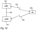
- Figure 10 is a simplified system architecture only showing some elements and functional entities, all being logical units whose implementation may differ from what is shown.
- the connections shown in Figure 10 are logical connections; the actual physical connections may be different. It is apparent to a person skilled in the art that the systems also comprise other functions and structures. It should be appreciated that the functions, structures, elements and the protocols used in or for CoMP, are irrelevant to the actual invention. Therefore, they need not to be discussed in more detail here.
- the exemplary radio system of Figure 10 comprises a network node 101 of a network operator.
- the network node 101 may include e.g. an LTE-A base station eNB1 of a first cell, radio network controller (RNC), or any other network element, or a combination of network elements.
- the network node 101 may be connected to one or more core network (CN) elements (not shown in Figure 10 ) such as a mobile switching centre (MSC), MSC server (MSS), mobility management entity (MME), serving gateway (SGW), gateway GPRS support node (GGSN), serving GPRS support node (SGSN), home location register (HLR), home subscriber server (HSS), visitor location register (VLR).
- MSC mobile switching centre
- MME mobility management entity
- SGW serving gateway
- GPRS support node GGSN
- serving GPRS support node SGSN
- HLR home subscriber server
- VLR visitor location register
- the radio network node 101 that may also be called eNB1 (enhanced node-B, evolved node-B) or network apparatus of the radio system, hosts the functions for radio resource management in the second cell of a public land mobile network.
- the exemplary radio system of Figure 10 comprises a network node 102 of a network operator.
- the network node 102 may include e.g.
- the network node 102 may be connected to one or more core network (CN) elements (not shown in Figure 10 ) such as a mobile switching centre (MSC), MSC server (MSS), mobility management entity (MME), serving gateway (SGW), gateway GPRS support node (GGSN), serving GPRS support node (SGSN), home location register (HLR), home subscriber server (HSS), visitor location register (VLR).
- CN core network
- the radio network node 102 that may also be called eNB2 (enhanced node-B, evolved node-B) or network apparatus of the radio system, hosts the functions for radio resource management in the second cell of the public land mobile network.
- FIG 10 shows a user equipment 103 located in the service area of the radio network node 101, 102.
- the user equipment refers to a portable computing device, and it may also be referred to as a user terminal.
- Such computing devices include wireless mobile communication devices operating with or without a subscriber identification module (SIM) in hardware or in soft-ware, including, but not limited to, the following types of devices: mobile phone, smart-phone, personal digital assistant (PDA), handset, laptop computer.
- SIM subscriber identification module
- the user equipment 103 is capable of connecting to the radio network node 101, 102 via a (cellular radio) connection 105, 106, respectively.
- the radio network node 101 may be capable of connecting to the radio network node 102 via a connection 104.
- Figure 11 is a block diagram of an apparatus according to an embodiment of the invention.
- Figure 11 shows a user equipment 103 located in the area of a radio network node 101, 102.
- the user equipment 103 is configured to be in connection with the radio network node 101, 102.
- the user equipment or UE 103 comprises a controller 111 operationally connected to a memory 112 and a transceiver 113.
- the controller 111 controls the operation of the user equipment 103.
- the memory 112 is configured to store software and data.
- the transceiver 113 is configured to set up and maintain a wireless connection 105, 106 to the radio network node 101, 102, respectively.
- the transceiver 113 is operationally connected to a set of antenna ports 114 connected to an antenna arrangement 115.
- the antenna arrangement 115 may comprise a set of antennas.
- the number of antennas may be one to four, for example.
- the number of antennas is not limited to any particular number.
- the user equipment 103 may also comprise various other components, such as a user interface, camera, and media player. They are not displayed in the figure due to simplicity.
- the radio network node 101, 102 such as an LTE-A base station (eNode-B, eNB) comprises a controller 116 operationally connected to a memory 117, and a transceiver 118.
- the controller 116 controls the operation of the radio network node 111.
- the memory 117 is configured to store software and data.
- the transceiver 118 is configured to set up and maintain a wireless connection to the user equipment 103 within the service area of the radio network node 101, 102.
- the transceiver 118 is operationally connected to an antenna arrangement 119.
- the antenna arrangement 119 may comprise a set of antennas.
- the number of antennas may be two to four, for example. The number of antennas is not limited to any particular number.
- the radio network node 101, 102 may be operationally connected (directly or indirectly) to another network element of the communication system, such as a further radio network node 101, 102 (via a connection 104), radio network controller (RNC), a mobility management entity (MME), a serving gateway (SGW), an MSC server (MSS), a mobile switching centre (MSC), a radio resource management (RRM) node, a gateway GPRS support node, an operations, administrations and maintenance (OAM) node, a home location register (HLR), a visitor location register (VLR), a serving GPRS support node, a gateway, and/or a server, via an interface 110.
- RNC radio network controller
- MME mobility management entity
- SGW serving gateway
- MSS MSC server
- MSC mobile switching centre
- RRM radio resource management
- gateway GPRS support node an operations, administrations and maintenance (OAM) node
- HLR home location register
- VLR visitor location register
- the apparatus 101, 102, 103 has been depicted as one entity, different modules and memory may be implemented in one or more physical or logical entities.
- the apparatus may also be a user terminal which is a piece of equipment or a device that associates, or is arranged to associate, the user terminal and its user with a subscription and allows a user to interact with a communications system.
- the user terminal presents information to the user and allows the user to input information.
- the user terminal may be any terminal capable of receiving information from and/or transmitting information to the network, connectable to the network wirelessly or via a fixed connection. Examples of the user terminals include a personal computer, a game console, a laptop (a notebook), a personal digital assistant, a mobile station (mobile phone), a smart phone, and a line telephone.
- the apparatus 101, 102, 103 may generally include a processor, controller, control unit or the like connected to a memory and to various inter-faces of the apparatus.
- the processor is a central processing unit, but the processor may be an additional operation processor.
- the processor may comprise a computer processor, application-specific integrated circuit (ASIC), field-programmable gate array (FPGA), and/or other hardware components that have been programmed in such a way to carry out one or more functions of an embodiment.
- ASIC application-specific integrated circuit
- FPGA field-programmable gate array
- the memory 112, 117 may include volatile and/or non-volatile memory and typically stores content, data, or the like.
- the memory 112, 117 may store computer program code such as software applications or operating systems, information, data, content, or the like for a processor to perform steps associated with operation of the apparatus in accordance with embodiments.
- the memory may be, for example, random access memory (RAM), a hard drive, or other fixed data memory or storage device. Further, the memory, or part of it, may be removable memory detachably connected to the apparatus.
- an apparatus implementing one or more functions of a corresponding mobile entity described with an embodiment comprises not only prior art means, but also means for implementing the one or more functions of a corresponding apparatus described with an embodiment and it may comprise separate means for each separate function, or means may be configured to perform two or more functions.
- these techniques may be implemented in hardware (one or more apparatuses), firmware (one or more apparatuses), software (one or more modules), or combinations thereof.
- firmware or software implementation can be through modules (e.g. procedures, functions, and so on) that perform the functions described herein.
- the software codes may be stored in any suitable, processor/computer-readable data storage medium(s) or memory unit(s) or article(s) of manufacture and executed by one or more processors/computers.
- the data storage medium or the memory unit may be implemented within the processor/computer or external to the processor/computer, in which case it can be communicatively coupled to the processor/computer via various means as is known in the art.
- a user terminal 103 may, in item 1200, periodically report CSIs to a serving CoMP-MA 101 serving the user terminal 103.
- the serving CoMP-MA collects CSIs transmitted by UEs, and forwards, in item 1201, the collected CSIs to eNBs 102 within a cooperating set.
- eNB1 101 may also receive CSIs forwarded 1202 from eNBs 102 for those UEs that are served by eNBs 102.
- the serving CoMP-MA 101 identifies and selects, in item 1203, one or more dominant interferers as potential candidates for transmitting eNBs for a selected UE.
- the serving CoMP-MA 101 receives PDCP PDUs from SGW.
- the serving CoMP-MA 101 initiates CoMP joint transmission by forwarding, in item 1205, to the candidate transmitting eNBs 102, the PDCP PDUs received from SGW and buffered for the selected UE 103, and by setting, in item 1206, the status of the selected UE to be CoMP joint transmission.
- the transmitting CoMP-MA at the candidate transmitting eNB 102 transmits, to the serving CoMP-MA 101, an acknowledgement on PDCP PDUs received in a candidate transmitting eNB 102 in case the candidate transmitting eNB 102 is capable of handling the CoMP joint transmission to UE.
- the serving CoMP-MA 101 Based on the acknowledgement, the serving CoMP-MA 101, measures 1208 the time spent between forwarding PDCP PDU to eNB2 102 and receiving the corresponding acknowledgement in eNB1 101. Based on the measurement, the serving CoMP-MA 101 adjusts 1208 a high threshold and a low threshold of predefined PDCP buffers of the serving CoMP-MA 101.
- the serving CoMP-MA 101 extracts 1208 radio resource allocations, RLC and MAC headers, references to user plane data included, and precoding matrices from corresponding protocol entities, and forwards 1209 the extracted radio resource allocations, RLC and MAC headers, references to the user plane data included, and precoding matrices to the transmitting eNBs 102 that have acknowledged PDCP PDUs, in order the transmitting CoMP-MA to be able to prepare for air interface scheduling for UE 103.
- the transmitting CoMP-MA schedules the air interface for UE 103 / performs air interface transmission to UE 103.
- Item 1211 illustrates simultaneous air interface transmission (CoMP-JT) transmitted from eNB1 101 to UE 103, which is simultaneous with the transmission 1210 from eNB2 102.
- FIG. 13 is a flow chart illustrating an exemplary embodiment.
- the apparatus 101 which may comprise e.g. a network element (network node, e.g. a LTE-A-capable base station (enhanced node-B, eNB1) of a first cell) may, in item 130, periodically receive reported CSIs by UEs. In item 131, the collected CSIs may be forwarded to eNBs 102 within a cooperating set. (In item 130, eNB 101 may also receive CSIs forwarded from eNBs 102 for those UEs that are served by eNBs 102).
- the serving CoMP-MA 101 Based on collected CSIs, the serving CoMP-MA 101 identifies and selects, in item 132, one or more dominant interferers as potential candidate transmitting eNBs for a selected UE 103. In item 133, the serving CoMP-MA 101 receives PDCP PDUs from SGW. The serving CoMP-MA 101 initiates CoMP joint transmission by forwarding, in item 134, to the candidate transmitting eNBs 102, the PDCP PDUs received from SGW and targeted to the selected UE 103, and by setting, in item 135, the status of the selected UE to be CoMP joint transmission.
- an acknowledgement is received from a candidate transmitting eNB 102, on PDCP PDUs received in the candidate transmitting eNB 102 in case the candidate transmitting eNB 102 is capable of handling the CoMP joint transmission to UE.
- the serving CoMP-MA 101 measures 137 the time spent between forwarding PDCP PDU to eNB2 102 and receiving the corresponding acknowledgement in eNB1 101. Based on the measurement, the serving CoMP-MA 101 adjusts 137 a high threshold and a low threshold of predefined PDCP buffers of the serving CoMP-MA 101.
- the serving CoMP-MA 101 extracts 138 radio resource allocations, RLC and MAC headers, references to user plane data included, and precoding matrices from corresponding protocol entities, and forwards 138 the extracted radio resource allocations, RLC and MAC headers, references to the user plane data included, and precoding matrices to the transmitting eNBs 102 that have acknowledged PDCP PDUs, in order the transmitting CoMP-MA to be able to prepare for air interface transmission for UE 103.
- simultaneous air interface transmission may take place from eNB 101 to UE 103 (parallel with eNB2 102 air interface transmission).
- FIG 14 is a flow chart illustrating an exemplary embodiment.
- the apparatus 102 which may comprise e.g. a network element (network node, e.g. a LTE-A-capable base station (enhanced node-B, eNB2) of a second cell) may, in item 140, receive collected CSIs from eNB1 101. (In item 140, eNB2 102 may also forward CSIs to eNBs 101 for those UEs that are served by eNB2 102).
- network node e.g. a LTE-A-capable base station (enhanced node-B, eNB2) of a second cell
- eNB2 102 may also forward CSIs to eNBs 101 for those UEs that are served by eNB2 102).
- the serving CoMP-MA 101 initiates CoMP joint transmission by forwarding to the candidate transmitting eNBs 102, the PDCP PDUs received from SGW and targeted to the selected UE 103, and by setting the status of the selected UE to be CoMP joint transmission.
- a candidate transmitting eNB 102 receives PDCP PDUs from eNB1 101.
- the transmitting CoMP-MA at eNB2 102 transmits, to the serving CoMP-MA 101, an acknowledgement on PDCP PDUs received in the candidate transmitting eNB 102 in case the candidate transmitting eNB2 102 is capable of handling the CoMP joint transmission to UE.
- eNB2 102 receives extracted radio resource allocations, RLC and MAC headers, references to the user plane data included, and precoding matrices from eNB1 101, in order the transmitting CoMP-MA 102 to be able to prepare for air interface scheduling for UE 103.
- the transmitting CoMP-MA schedules the air interface for UE 103.
- a serving eNB may transmit PDCP PDUs to the other eNBs in the CoMP transmitting set beforehand (based on an appositely configured buffer threshold that depends on a X2 RTT time).
- a specific PDCP PDU is scheduled in the serving eNB, only control information needs to be signaled to the other eNBs in the CoMP transmitting set.
- An exemplary embodiment makes it possible for inter-eNB CoMP joint transmission schemes to be implemented with relaxed backhaul/transport constraints. There may be delay requirements only for control information. Data rate and delay requirements for U-plane data are relaxed due to in advance forwarding, as well as due to the fact that forwarding of precoded data may not be needed.
- the data to be CoMP-transmitted over the X2 interface from a nominated coordinating eNB may be shared to the others participating as PDCP-level packets, well in advance of the eventual time of transmission on the radio interface. Once the time of a scheduling decision comes, it may be sent along with necessary delay-critical RLC/MAC-level instructions over the same X2 interface as prioritized packets, i.e. bypassing any buffering queues of non-delay critical data on the way.
- An exemplary embodiment may involve splitting C-plane and U-plane data from X2 point of view, and giving a high priority on scheduling related information.
- the steps/points, signalling messages and related functions de-scribed above in Figures 1 to 14 are in no absolute chronological order, and some of the steps/points may be performed simultaneously or in an order differing from the given one. Other functions can also be executed between the steps/points or within the steps/points and other signalling messages sent be-tween the illustrated messages. Some of the steps/points or part of the steps/points can also be left out or replaced by a corresponding step/point or part of the step/point.
- the apparatus operations illustrate a procedure that may be implemented in one or more physical or logical entities.
- the signalling messages are only exemplary and may even comprise several separate messages for transmitting the same information. In addition, the messages may also contain other information.
- a method comprising collecting, in a serving CoMP-MA, channel state information, CSIs, periodically reported by user terminals served by a base station within a cooperating set, and forwarding the CSIs periodically reported by the user terminals served by said base station to other base stations within the cooperating set; based on the collected CSIs, identifying and selecting, in the serving CoMP-MA, one or more dominant interferers as potential candidates for transmitting network nodes for a selected user terminal; initiating CoMP joint transmission by forwarding, to the candidates for the transmitting network node for the selected user terminal, PDCP PDUs received from a serving gateway and targeted to the selected user terminal and setting the status of the selected user terminal to joint transmission; receiving an acknowledgement on PDCP PDUs received in a candidate for the transmitting network node, in case the candidate transmitting network node is capable of handling the joint transmission to the user terminal; measuring, in the serving CoMP-MA, time spent between forwarding PDCP PDU and receiving a
- a method comprising defining a cooperating set comprising selected base stations, wherein members of the cooperating set exchange information including CSI, DL user data and control messages required for proper CoMP operation; defining one or more transmission sets comprising selected base stations of the cooperating set, wherein members of the transmission set simultaneously transmit to a given user terminal; wherein a serving base station serving the user terminal instructs other network nodes from the transmission set to allocate radio resources for its own user terminals, and sends them the DL user data to be transmitted and instructions necessary for coordinated transmission, and wherein a transmitting network node within the transmission set transmits with CoMP JT to a user terminal whose serving base station is a different base station, and receives DL user data and instructions necessary for transmission from the serving base station of the user terminal.
- the member network nodes of the cooperating set remain the same during operation unless reconfigured by a network operator.
- the members of the transmission set are selected dynamically from the cooperating set, such that the transmission set is a subset of the cooperating set.
- each base station within the cooperation set which is not its own serving base station is a potential transmitting network node.
- RTT measurements for a given X2 interface are aggregated into a common high and low threshold.
- a method comprising defining two modes of operation of CoMP-MA, such that CoMP-MA acts as the serving CoMP-MA for user terminals served by base station at which CoMP-MA is attached, and as the transmitting CoMP-MA for user terminals that receive CoMP joint transmission but for which the serving base station is a remote base station.
- CSIs received through Uu interface are filtered to preselect only those user terminals for CoMP joint transmission that have data in their PDCP buffer waiting to be forwarded over the air interface.
- the pre-selection of the user terminals for CoMP joint transmission comprises identifying candidate user terminals and their candidate transmitting network nodes that are eligible for CoMP joint transmission based on the received CSIs; evaluating the status of the candidate user terminal's PDCP buffer.
- a method comprising serving the user terminal at a cell edge with CoMP joint transmission, due to a high interference from other cells.
- a timer based packet discard is employed prohibiting PDUs from being queued for too long, wherein the base stations within the cooperating set are configured with the same discard timer set to a value above a maximum allowed X2 interface RTT.
- a method comprising negotiating with RRC to perform cross-cell scheduling considering only those PRBs that are allocated for CoMP joint transmission and to the transmitting network node in question, to prevent conflicting cross-cell scheduling where two base stations schedule on the same PRB of the same base station.
- PDCP PDUs are scheduled at the serving base station, they are handed over to a RLC layer which executes required protocol operations, and then forwards the resulting RLC PDUs to a MAC layer, wherein RLC PDUs are encapsulated, handed over to a physical layer, and transmitted synchronously from each transmitting network node
- the method comprises immediately forwarding, from the serving base station, the retransmission request to each transmitting network node within a scheduling command.
- the scheduling command is created so that relevant information that enables the transmitting network node and/or transmitting CoMP-MA to create an exact replica of MAC PDUs to be scheduled at the same time is included, and information required for physical layer processing, wherein the scheduling command is delivered as high priority data over the X2 interface.
- the scheduling command comprises PDCCH information, information for replication of MAC PDUs, and precoding matrices.
- the transmitting network nodes are informed of specific radio resource allocation and modulation and coding schemes used in order to synchronize transmission, wherein PDCCH data is forwarded from the serving CoMP-MA to the transmitting CoMP-MAs over the X2 interface, along with the PCFICH information for the interpretation of a PDCCH field.
- RLC protocol information is sent in order to reconstruct RLC PDUs, the RLC protocol information including status PDUs, and, in acknowledged mode AM and unacknowledged mode UM, RLC headers used during the encapsulation.
- information used to reassemble PDCP PDUs comprises a sequence number of PDCP SDU, which is the same as a sequence number of a corresponding PDCP PDU, and in case of an RLC SDU segment, a starting offset of scheduled data from PDCP PDU.
- a first apparatus comprises at least one processor; and at least one memory including a computer program code, wherein the at least one memory and the computer program code are configured to, with the at least one processor, cause the first apparatus to collect channel state information, CSIs, periodically reported by user terminals served by a base station within a cooperating set and forward the CSIs periodically reported by the user terminals served by said base station to other base stations within the cooperating set; based on the collected CSIs, identify and select one or more dominant interferers as potential candidates for transmitting network nodes for a selected user terminal; initiate CoMP joint transmission by forwarding, to the candidates for the transmitting network node for the selected user terminal, PDCP PDUs received from a serving gateway and targeted to the selected user terminal and set the status of the selected user terminal to joint transmission; receive an acknowledgement on PDCP PDUs received in a candidate for the transmitting network node, in case the candidate transmitting network node is capable of handling the joint transmission to the user terminal; measure time spent between forwarding
- the at least one memory and the computer program code are configured to, with the at least one processor, cause the first apparatus to perform any of the method steps.
- a second apparatus comprises at least one processor; and at least one memory including a computer program code, wherein the at least one memory and the computer program code are configured to, with the at least one processor, cause the second apparatus to forward, to other base stations within a cooperating set, channel state information, CSIs, periodically reported by user terminals served by the second apparatus; receive, from a serving CoMP-MA, channel state information, CSIs, collected from user terminals within a cooperating set, wherein one or more dominant interferers are selected in the serving CoMP-MA as potential candidates for transmitting network nodes for a selected user terminal; receive, from the serving CoMP-MA, PDCP PDUs received from a serving gateway and targeted to the selected user terminal, wherein CoMP joint transmission is initiated and the status of the selected user terminal is set to joint transmission; transmit, to the serving CoMP-MA, an acknowledgement on the received PDCP PDUs, in case a candidate transmitting network node is capable of handling the joint transmission to the user terminal; receive, from a serving CoMP-
- the at least one memory and the computer program code are configured to, with the at least one processor, cause the second apparatus to identify, upon the reception of a forwarded PDCP PDU belonging to the user terminal, based on a tunnel endpoint identifier field of a GTP-U header used in a user plane X2.
- the at least one memory and the computer program code are configured to, with the at least one processor, cause the second apparatus to, if the second apparatus is overloaded, discard PDCP PDU in order not to take part in the CoMP joint transmission.
- the at least one memory and the computer program code are configured to, with the at least one processor, cause the second apparatus to when the scheduling command is received, extract the relevant information, select PDCP PDUs indicated in the command and create corresponding MAC PDUs that are exact replicas of those created at the serving base station.
- the at least one memory and the computer program code are configured to, with the at least one processor, cause the second apparatus to negotiate cross-cell scheduling decisions with RRC, wherein when a cross-cell scheduling decision is made, a scheduling command immediately assembled, based on which and previously received PDCP PDUs, MAC PDUs are assembled which are conveyed to a physical layer.
- a computer program product comprising program code means configured to perform any of the method steps when the program is run on a computer.
- a computer-readable storage medium comprising program code means configured to perform any of the method steps when executed on a computer.
Landscapes
- Engineering & Computer Science (AREA)
- Computer Networks & Wireless Communication (AREA)
- Signal Processing (AREA)
- Mobile Radio Communication Systems (AREA)
Claims (15)
- Verfahren für eine koordinierte Mehrpunktübertragung in einem Kommunikationssystem, wobei das Verfahren Folgendes umfasst
Erfassen (130) von Kanalzustandsinformationen (CSI), die in regelmäßigen Abständen von durch eine Basisstation innerhalb einer kooperierenden Gruppe versorgten Benutzerstationen gemeldet werden, in einem versorgenden koordinierten Mehrpunkt-Managementagenten (CoMP-MA) und Weiterleiten (131) der von den durch die Basisstation versorgten Benutzerstationen in regelmäßigen Abständen gemeldeten Kanalzustandsinformationen (CSI) an andere Basisstationen innerhalb der kooperierenden Gruppe;
gekennzeichnet durch
Identifizieren und Auswählen (132) eines oder mehrerer dominanten Störern als potentielle Kandidaten für Sendenetzknoten für eine ausgewählte Benutzerstation (103) in dem versorgenden koordinierten Mehrpunkt-Managementagenten auf Grundlage der erfassten Kanalzustandsinformationen (CSI);
Initiieren von gemeinsamer koordinierter Mehrpunktübertragung (CoMP JT) durch Weiterleiten (134) von von einem versorgenden Gateway empfangenen und an die ausgewählte Benutzerstation gerichteten Protokolldateneinheiten (PDU) des Paketdaten-Konvergenzprotokolls (PDCP) an die Kandidaten für die Sendenetzknoten für die ausgewählte Benutzerstation mittels einer X2-Schnittstelle und Setzen (135) des Zustands der ausgewählten Benutzerstation auf gemeinsame Übertragung;
Empfangen (130) einer Empfangsbestätigung mittels der X2-Schnittstelle über die in einem Kandidaten für die Sendenetzknoten empfangenen Protokolldateneinheiten (PDU) des Paketdaten-Konvergenzprotokolls (PDCP), wenn der Sendenetzknotenkandidat fähig ist, die gemeinsame Übertragung an die Benutzerstation abzuwickeln;
Messen (137) der Zeit, die zwischen dem Weiterleiten der Protokolldateneinheiten (PDU) des Paketdaten-Konvergenzprotokolls (PDCP) und dem Empfangen einer entsprechenden Empfangsbestätigung mittels der X2-Schnittstelle vergangen ist, in dem versorgenden koordinierten Mehrpunkt-Managementagenten (CoMP-MA);
Anpassen (137) eines oberen Schwellenwerts und eines unteren Schwellenwerts von vordefinierten Paketdaten-Konvergenzprotokollpuffern des versorgenden koordinierten Mehrpunkt-Managementagenten (CoMP-MA) auf Grundlage der Messung;
als Reaktion darauf, dass für Luftschnittstellenplanung erforderliche Funkinformationen verfügbar werden, Extrahieren von Funkressourcenzuweisungen, Kopfdaten zu Funkverbindungssteuerung (RLC) und Mediumzugangssteuerung (MAC), Referenzen zu eingeschlossenen Benutzerebenedaten und zeitlich vorangegangenen Matrizen aus entsprechenden Protokollinstanzen im versorgenden koordinierten Mehrpunkt-Managementagenten (CoMP-MA),
Weiterleiten (138) der extrahierten Funkressourcenzuweisungen, Kopfdaten zu Funkverbindungssteuerung (RLC) und Mediumzugangssteuerung (MAC), Referenzen zu eingeschlossenen Benutzerebenedaten und zeitlich vorangegangenen Matrizen an die Sendenetzknoten (102), die den Empfang von Protokolldateneinheiten (PDU) des Paketdaten-Konvergenzprotokolls (PDCP) bestätigt haben, mittels der X2-Schnittstelle, damit ein dem Sendenetzknoten zugeordneter sendender koordinierter Mehrpunkt-Managementagent (CoMP-MA) in der Lage ist, sich auf Luftschnittstellenplanung für die Benutzerstation vorzubereiten. - Verfahren nach dem Anspruch 1, wobei das Verfahren Folgendes umfasst
Definieren einer ausgewählte Basisstationen umfassenden kooperierenden Gruppe, wobei Mitglieder der kooperierenden Gruppe Informationen einschließlich Kanalzustandsinformationen (CSI), Downlink(DL)-Benutzerdaten und Steuerungsnachrichten, die für einen ordnungsgemäßen koordinierten Mehrpunktbetrieb (CoMP) erforderlich sind, austauschen;
Definieren einer oder mehrerer Sendegruppen, die ausgewählte Basisstationen der kooperierenden Gruppe umfassen, wobei Mitglieder der Sendegruppe gleichzeitig an eine vorgegebene Benutzerstation senden;
wobei eine versorgende Basisstation, die die Benutzerstation versorgt, andere Netzknoten der Sendegruppe anweist, Funkressourcen für ihre eigenen Benutzerstationen zuzuweisen, und ihnen die zu sendenden Downlink-Benutzerdaten und die für koordinierte Übertragung erforderlichen Anweisungen sendet, und
wobei ein Sendenetzknoten innerhalb der Sendegruppe mittels gemeinsamer koordinierter Mehrpunktübertragung (CoMP JT) an eine Benutzerstation, deren versorgende Basisstation eine abweichende Basisstation ist, sendet und Downlink-Benutzerdaten und für die Übertragung erforderliche Anweisungen von der versorgenden Basisstation der Benutzerstation empfängt. - Verfahren nach dem Anspruch 1 oder 2, wobei
die Netzknotenmitglieder der kooperierenden Gruppe während des Betriebs dieselben bleiben, sofern sie nicht von einem Netzbetreiber rekonfiguriert werden;
die Mitglieder der Sendegruppe dynamisch aus der kooperierenden Gruppe ausgewählt werden, so dass die Sendegruppe eine Untergruppe der kooperierenden Gruppe ist; und/oder
für eine beliebige Benutzerstation gilt, dass jede Basisstation innerhalb der kooperierenden Gruppe, die nicht ihre eigene versorgende Basisstation ist, ein potentieller Sendenetzknoten ist. - Verfahren nach einem beliebigen der vorstehenden Ansprüche,
wobei die Messungen der Paketumlaufzeit (RTT) einer beliebigen X2-Schnittstelle innerhalb einer gemeinsamen oberen und unteren Schwelle zusammengeschlossen werden. - Verfahren nach einem beliebigen der vorstehenden Ansprüche,
wobei das Verfahren das Definieren von zwei Betriebsmodi des koordinierten Mehrpunkt-Managementagenten (CoMP-MA) umfasst, so dass der koordinierte Mehrpunkt-Managementagent als der versorgende koordinierte Mehrpunkt-Managementagent für von der Basisstation, an die der koordinierte Mehrpunkt-Managementagent angebunden ist, versorgte Benutzerstationen und als der sendende koordinierte Mehrpunkt-Managementagent für Benutzerstationen, die gemeinsame koordinierte Mehrpunktübertragung empfangen, aber deren versorgende Basisstation eine entfernte Basisstation ist, agiert. - Verfahren nach einem beliebigen der vorstehenden Ansprüche,
wobei zur Reduzierung der X2-Schnittstellenlast durch die Uu-Schnittstelle empfangene Kanalzustandsinformationen (CSI) gefiltert werden, um für die gemeinsame koordinierte Mehrpunktübertragung lediglich solche Benutzerstationen vorzuwählen, bei denen Daten in ihrem Paketdaten-Konvergenzprotokollpuffer darauf warten, über die Luftschnittstelle weitergeleitet zu werden,
wobei die Vorauswahl der Benutzerstationen für gemeinsame koordinierte Mehrpunktübertragung Folgendes umfasst
Identifizieren auf Grundlage der empfangenen Kanalzustandsinformationen (CSI) von Benutzerstationskandidaten und ihren Sendenetzknotenkandidaten, die für gemeinsame koordinierte Mehrpunktübertragung geeignet sind;
Beurteilen des Zustands des Paketdaten-Konvergenzprotokollpuffers des Benutzerstationskandidaten. - Verfahren nach einem beliebigen der vorstehenden Ansprüche,
wobei das Verfahren das Versorgen der Benutzerstation an einem Zellenrand mit gemeinsamer koordinierter Mehrpunktübertragung aufgrund starker Störungen durch andere Zellen umfasst. - Verfahren nach einem beliebigen der vorstehenden Ansprüche,
wobei in einer PDCP-Schicht eine zeitgesteuerte Paketverwerfung eingesetzt wird, die verhindert, dass Protokolldateneinheiten (PDU) zu lange auf eine Abarbeitung warten, wobei die Basisstationen innerhalb der kooperierenden Gruppe mit demselben Verwerfungstimer, der auf einen Wert oberhalb einer maximal zulässigen X2-Schnittstellen-Paketumlaufzeit gesetzt ist, konfiguriert sind. - Verfahren nach einem beliebigen der vorstehenden Ansprüche,
wobei das Verfahren ein Verhandeln mit Funkressourcensteuerung (RCC) zum Durchführen von zellübergreifender Ablaufplanung unter Berücksichtigung lediglich derjenigen physischen Ressourcenblöcke (PRB), die für gemeinsame koordinierte Mehrpunktübertragung und den jeweiligen Sendenetzknoten zugewiesen sind, umfasst, um kollidierende zellübergreifende Ablaufplanung, bei der zwei Basisstationen auf demselben physischen Ressourcenblock (PRB) derselben Basisstation planen, zu verhindern. - Verfahren nach einem beliebigen der vorstehenden Ansprüche,
wobei das Verfahren das unmittelbare Weiterleiten der Neuübertragungsanforderung von der versorgenden Basisstation an alle Sendenetzknoten innerhalb eines Planungsbefehls umfasst, wenn die Benutzerstation ihrem Versorgungsknoten signalisiert, dass die Benutzerstation eine HARQ-Neuübertragung erfordert,
wobei der Planungsbefehl erstellt wird, so dass relevante Informationen, die dem Sendenetzknoten und/oder dem sendenden koordinierten Mehrpunkt-Managementagenten ermöglichen, ein genaues Replikat der zur selben Zeit geplanten Mediumzugangssteuerung-Protokolldateneinheiten (MAC PDU) zu erstellen, und für die Bitübertragungsschichtverarbeitung erforderliche Informationen eingeschlossen sind, wobei der Planungsbefehl als Daten mit hoher Priorität über die X2-Schnittstelle geliefert wird,
wobei der Planungsbefehl Informationen zum Abwärtsstrecken-Steuerungskanal (PDCCH), Informationen zur Replikation von Mediumzugangssteuerungs-Protokolldateneinheiten (MAC PDU) und zeitlich vorangegangene Matrizen enthält. - Verfahren nach einem beliebigen der vorstehenden Ansprüche,
wobei die Sendenetzknoten über spezifische Funkressourcenzuweisungen und Modulations- und Codierungsschemata, die verwendet werden, um die Übertragung zu synchronisieren, informiert werden, wobei PDCCH-Daten gemeinsam mit Informationen zum physikalischen Steuerformatindikatorkanal (PCFICH) für die Auswertung eines PDCCH-Feldes vom versorgenden koordinierten Mehrpunkt-Managementagenten mittels der X2-Schnittstelle an die sendenden koordinierten Mehrpunkt-Managementagenten (CoMP-MA) weitergeleitet werden. - Verfahren nach einem beliebigen der vorstehenden Ansprüche,
wobei Protokollinformationen der Funkverbindungssteuerung (RLC) gesendet werden, um Funkverbindungssteuerung-Protokolldateneinheiten (RLC PDU) zu rekonstruieren, wobei die Protokollinformationen der Funkverbindungssteuerung (RLC) Zustandsprotokolldateneinheiten (PDU) und im bestätigten Modus AM und im unbestätigten Modus UM während der Kapselung verwendete Kopfdaten der Funkverbindungssteuerung (RLC) einschließen. - Verfahren nach einem beliebigen der vorstehenden Ansprüche,
wobei Informationen, die verwendet werden, um Protokolldateneinheiten (PDU) von Paketdaten-Konvergenzprotokollen (PDCP) wieder zusammenzusetzen, Folgendes umfassen
eine Sequenznummer einer Dienstdateneinheit (SDU) des Paketdaten-Konvergenzprotokolls (PDCP), die mit einer Sequenznummer einer entsprechenden Protokolldateneinheit (PDU) des Paketdaten-Konvergenzprotokolls (PDCP) identisch ist, und
ein Startoffset geplanter Daten der Protokolldateneinheit (PDU) des Paketdaten-Konvergenzprotokolls (PDCP) im Fall eines Segments einer Dienstdateneinheit (SDU) der Funkverbindungssteuerung (RLC). - Erstes Gerät, das wenigstens einen Prozessor und wenigstens einen Speicher einschließlich eines Computerprogrammcodes umfasst, wobei der wenigstens eine Speicher und der Computerprogrammcode ausgelegt sind, um mit dem wenigstens einen Prozessor das erste Gerät (101) dazu zu bringen, jeden beliebigen der Verfahrensschritte der Ansprüche 1 - 13 vorzunehmen.
- System, das Folgendes umfasst:ein erstes Gerät (101) nach dem Anspruch 14, das einen versorgenden koordinierten Mehrpunkt-Managementagenten (CoMP-MA) aufweist;ein zweites Gerät (102), das mit dem ersten Gerät mittels einer X2-Schnittstelle verbunden ist und wenigstens einen Prozessor und wenigstens einen Speicher einschließlich eines Computerprogrammcodes umfasst, wobei der wenigstens eine Speicher und der Computerprogrammcode ausgelegt sind, um mit dem wenigstens einen Prozessor das zweite Gerät (102) zu Folgendem zu bringenWeiterleiten von Kanalzustandsinformationen (CSI), die von durch das zweite Gerät versorgten Benutzerstationen in regelmäßigen Abständen gemeldet werden, an andere Basisstationen innerhalb einer kooperierenden Gruppe;Empfangen von Kanalzustandsinformationen (CSI), die von Benutzerstationen innerhalb einer kooperierenden Gruppe erfasst wurden, vom versorgenden koordinierten Mehrpunkt-Managementagenten (CoMP-MA);Empfangen von Paketdateneinheiten (PDU) des Paketdaten-Konvergenzprotokolls (PDCP), die von einem versorgenden Gateway empfangen wurden und an die ausgewählte Benutzerstation gerichtet sind, vom versorgenden koordinierten MehrpunktManagementagenten (CoMP-MA), wobei eine gemeinsame koordinierte Mehrpunktübertragung initiiert wird und der Zustand der ausgewählten Benutzerstation auf gemeinsame Übertragung gesetzt wird;Senden einer Empfangsbestätigung über die empfangenen Protokolldateneinheiten (PDU) des Paketdaten-Konvergenzprotokolls (PDCP) an den versorgenden koordinierten Mehrpunkt-Managementagenten (CoMP-MA), wenn das zweite Gerät in der Eigenschaft als Sendenetzknotenkandidat fähig ist, die gemeinsame Übertragung an die Benutzerstation abzuwickeln;Empfangen von extrahierten Funkressourcenzuweisungen, Kopfdaten zu Funkverbindungssteuerung (RLC) und Mediumzugangssteuerung (MAC), Referenzen zu den eingeschlossenen Benutzerebenedaten und zeitlich vorangegangenen Matrizen von dem versorgenden koordinierten Mehrpunkt-Managementagenten (CoMP-MA), damit ein dem Sendenetzknoten zugeordneter sendender koordinierter Mehrpunkt-Managementagent (CoMP-MA) in der Lage ist, sich auf Luftschnittstellenplanung für die Benutzerstation vorzubereiten.
Applications Claiming Priority (1)
| Application Number | Priority Date | Filing Date | Title |
|---|---|---|---|
| PCT/EP2013/055412 WO2014139588A1 (en) | 2013-03-15 | 2013-03-15 | Coordinated multipoint joint transmission with relaxed backhaul requirements |
Publications (2)
| Publication Number | Publication Date |
|---|---|
| EP2974490A1 EP2974490A1 (de) | 2016-01-20 |
| EP2974490B1 true EP2974490B1 (de) | 2017-12-06 |
Family
ID=47901984
Family Applications (1)
| Application Number | Title | Priority Date | Filing Date |
|---|---|---|---|
| EP13710837.9A Active EP2974490B1 (de) | 2013-03-15 | 2013-03-15 | Gemeinsame koordinierte mehrpunktübertragung mit reduzierten backhaul-anforderungen |
Country Status (3)
| Country | Link |
|---|---|
| US (1) | US10334585B2 (de) |
| EP (1) | EP2974490B1 (de) |
| WO (1) | WO2014139588A1 (de) |
Families Citing this family (65)
| Publication number | Priority date | Publication date | Assignee | Title |
|---|---|---|---|---|
| JP5758354B2 (ja) * | 2012-07-04 | 2015-08-05 | 株式会社Nttドコモ | 無線通信システム |
| WO2015016550A1 (en) * | 2013-07-29 | 2015-02-05 | Lg Electronics Inc. | Method for calculating and reporting a buffer status and device therefor |
| EP3032874B1 (de) * | 2013-08-07 | 2023-03-08 | Sony Group Corporation | Kommunikationssteuerungsvorrichtung, kommunikationssteuerungsverfahren und kommunikationsvorrichtung |
| WO2015053516A1 (ko) * | 2013-10-11 | 2015-04-16 | 엘지전자 주식회사 | 클라우드 랜 환경에서 rrh의 전원을 제어하는 방법 |
| CN105309018B (zh) * | 2013-10-31 | 2019-07-09 | 华为技术有限公司 | 一种传输方法和装置 |
| KR20160090804A (ko) * | 2013-12-04 | 2016-08-01 | 엘지전자 주식회사 | 클라우드 무선 통신 시스템에서 시스템 정보 송수신 방법 및 이를 위한 장치 |
| WO2015137772A1 (en) * | 2014-03-13 | 2015-09-17 | Samsung Electronics Co., Ltd. | Method and apparatus for performing coordinated communication in a communication system |
| US20150312893A1 (en) * | 2014-03-19 | 2015-10-29 | Nec Laboratories America, Inc. | Signalling for Coordinated Multi-Point Transmission and Reception (CoMP) |
| US9888469B2 (en) | 2014-03-19 | 2018-02-06 | Nec Corporation | Signalling for coordinated multi-point transmission and reception (CoMP) |
| US10778334B2 (en) * | 2014-06-06 | 2020-09-15 | Vivint, Inc. | Fiber/wireless hybrid solution |
| US10230431B2 (en) | 2014-09-12 | 2019-03-12 | Parallel Wireless, Inc. | Low-latency inter-eNodeB coordinated multi-point transmission |
| US10224986B2 (en) * | 2014-09-25 | 2019-03-05 | Nec Corporation | Signalling in coordinated multi-point transmission and reception (CoMP) |
| US10230507B2 (en) | 2014-09-25 | 2019-03-12 | Nec Corporation | Signalling in coordinated multi-point transmission and reception (CoMP) |
| US9775017B2 (en) | 2014-09-26 | 2017-09-26 | Parallel Wireless, Inc. | Enabling high-power UE transmission |
| CN105451210A (zh) * | 2014-09-29 | 2016-03-30 | 中兴通讯股份有限公司 | 数据同步处理方法及装置 |
| JP6361739B2 (ja) * | 2014-11-07 | 2018-07-25 | 日本電気株式会社 | 無線通信システム、基地局、通信方法 |
| EP3216261B1 (de) * | 2014-11-07 | 2021-06-23 | Parallel Wireless, Inc. | Selbstkalibrierendes und selbsteinstellendes netzwerk |
| US9906973B2 (en) * | 2014-11-28 | 2018-02-27 | Industrial Technology Research Institute | Evolved NodeB and traffic dispatch method thereof |
| US9794944B2 (en) * | 2015-03-13 | 2017-10-17 | Qualcomm Incorporated | System and method for mobility tracking of user equipment |
| US9998355B2 (en) * | 2015-03-16 | 2018-06-12 | Huawei Technologies Co., Ltd. | Methods and systems for traffic engineering with redundancy |
| US10158463B1 (en) * | 2015-03-17 | 2018-12-18 | Sprint Spectrum L.P. | Method and system for coordinated transmission with use of neighboring base station scheduling policy |
| US20170012751A1 (en) * | 2015-07-07 | 2017-01-12 | Huawei Technologies Co., Ltd. | Multipoint Radio Link Control (RLC) Coordinator for Loosely Coordinated Multipoint Communications |
| CN113747418B (zh) * | 2015-08-05 | 2024-05-14 | IPCom两合公司 | Sfn节点间消息发送 |
| CN108141815A (zh) * | 2015-08-14 | 2018-06-08 | 瑞典爱立信有限公司 | 无线网络中的系统信息广播 |
| PL3354059T3 (pl) * | 2015-09-24 | 2021-01-25 | Nokia Solutions And Networks Oy | Raportowanie mierników jakości usług łącza w górę |
| WO2017070904A1 (zh) | 2015-10-29 | 2017-05-04 | 华为技术有限公司 | 一种多小区上行协作通信的方法和基站 |
| CN108353273B (zh) | 2015-10-31 | 2021-11-19 | 并行无线公司 | 弹性调度 |
| KR102138111B1 (ko) * | 2015-11-30 | 2020-07-27 | 후아웨이 테크놀러지 컴퍼니 리미티드 | 스케줄링 장치, 피스케줄링 장치, 및 자원 스케줄링 방법과 장치 |
| EP3403422A4 (de) | 2016-01-13 | 2019-08-07 | Parallel Wireless Inc. | Planer zur wiederverwendung von fraktionaler frequenz zwischen zellen |
| CN115066004A (zh) * | 2016-01-21 | 2022-09-16 | 索尼公司 | 电子设备和通信方法 |
| US10165530B2 (en) * | 2016-03-22 | 2018-12-25 | Christoph RULAND | Verification of time information transmitted by time signals or time telegrams |
| CN107493689B (zh) * | 2016-04-11 | 2021-04-13 | 日本电信电话株式会社 | 无线通信系统、中央站装置、分布站装置及其通信方法 |
| WO2017185329A1 (zh) * | 2016-04-29 | 2017-11-02 | 华为技术有限公司 | 数据传输方法、远端节点及控制节点 |
| EP3430830B1 (de) * | 2016-05-20 | 2021-09-22 | Huawei Technologies Co., Ltd. | Steuerknoten und verfahren dafür |
| US20170353219A1 (en) * | 2016-06-02 | 2017-12-07 | Zte Wistron Telecom Ab | Small cell distributed precoding |
| CN107623931B (zh) * | 2016-07-14 | 2021-11-02 | 中兴通讯股份有限公司 | 多点协作的分组管理方法、装置及系统 |
| CN108206726B (zh) * | 2016-12-20 | 2022-07-19 | 中兴通讯股份有限公司 | 一种合并小区的数据处理方法、装置及系统 |
| US10341225B2 (en) * | 2016-12-30 | 2019-07-02 | Hughes Network Systems, Llc | Bonding of satellite terminals |
| CN108289007B (zh) * | 2017-01-10 | 2022-04-15 | 中兴通讯股份有限公司 | 数据包传输方法及装置 |
| CN106788622B (zh) * | 2017-01-13 | 2020-06-16 | 西安电子科技大学 | 无线局域网以用户为中心的下行多点协作传输方法 |
| US20180205429A1 (en) * | 2017-01-17 | 2018-07-19 | Qualcomm Incorporated | Methods and systems for simultaneous multi access point transmissions on a wireless channel |
| US10484158B2 (en) | 2017-01-24 | 2019-11-19 | Hong Kong Applied Science and Technology Research Institute Company Limited | Method and apparatus for resource allocation signaling in a joint transmission cellular communication system |
| EP3592039B1 (de) * | 2017-03-23 | 2021-09-01 | Guangdong Oppo Mobile Telecommunications Corp., Ltd. | Drahtloskommunikationsverfahren und -vorrichtung |
| CN110945901B (zh) * | 2017-04-24 | 2022-03-01 | 摩托罗拉移动有限责任公司 | 复制用于无线电承载的pdcp pdu |
| CN110677878B (zh) * | 2017-05-05 | 2021-04-09 | 华为技术有限公司 | 数据传输方法、装置、设备及系统 |
| US10477593B2 (en) * | 2017-06-08 | 2019-11-12 | Qualcomm Incorporated | Techniques and apparatuses for access in a backhaul network |
| EP3619898A1 (de) * | 2017-06-16 | 2020-03-11 | Huawei Technologies Co., Ltd. | Steuerungsvorrichtung, netzwerkknoten und verfahren dafür |
| WO2019100377A1 (zh) * | 2017-11-27 | 2019-05-31 | 华为技术有限公司 | 小区间协同调度方法、装置及设备 |
| US11057957B2 (en) * | 2018-10-09 | 2021-07-06 | Cable Television Laboratories, Inc. | Systems and methods for joint wireless transmission and joint wireless reception |
| US10834645B2 (en) * | 2018-11-30 | 2020-11-10 | Google Llc | Active coordination set for mobility management |
| US11224081B2 (en) | 2018-12-05 | 2022-01-11 | Google Llc | Disengaged-mode active coordination set management |
| WO2020131750A1 (en) * | 2018-12-18 | 2020-06-25 | XCOM Labs, Inc. | User equipment configured for increased data rate |
| US10756795B2 (en) | 2018-12-18 | 2020-08-25 | XCOM Labs, Inc. | User equipment with cellular link and peer-to-peer link |
| US11063645B2 (en) | 2018-12-18 | 2021-07-13 | XCOM Labs, Inc. | Methods of wirelessly communicating with a group of devices |
| US11330649B2 (en) | 2019-01-25 | 2022-05-10 | XCOM Labs, Inc. | Methods and systems of multi-link peer-to-peer communications |
| JP7414402B2 (ja) * | 2019-04-10 | 2024-01-16 | キヤノン株式会社 | 通信装置、通信装置の制御方法、およびプログラム |
| US20220263614A1 (en) * | 2019-07-08 | 2022-08-18 | Telefonaktiebolaget Lm Ericsson (Publ) | Method and Devices for Wireless Communication |
| EP4005101B1 (de) * | 2019-09-19 | 2023-12-20 | Google LLC | Verbesserte strahlsuche für aktive koordinationssätze |
| CN110943811B (zh) * | 2019-11-20 | 2021-07-13 | 西安培华学院 | 一种用于多点传输的数据分流及harq进程分配的方法和系统 |
| TWI833004B (zh) * | 2020-04-07 | 2024-02-21 | 智易科技股份有限公司 | 通訊系統及其資料傳輸方法與使用者裝置 |
| US20210352506A1 (en) * | 2020-05-07 | 2021-11-11 | Qualcomm Incorporated | Layer 1 measurement reporting using measurement index |
| US20220053491A1 (en) * | 2020-08-17 | 2022-02-17 | Charter Communications Operating, Llc | Methods and apparatus for spectrum utilization coordination between wireline backhaul and wireless systems |
| US11844057B2 (en) | 2020-09-09 | 2023-12-12 | Charter Communications Operating, Llc | Methods and apparatus for wireless data traffic management in wireline backhaul systems |
| WO2023123002A1 (zh) * | 2021-12-28 | 2023-07-06 | 北京小米移动软件有限公司 | 信息上报方法、装置、设备及存储介质 |
| CN114615687B (zh) * | 2022-03-22 | 2023-06-27 | 重庆邮电大学 | 一种时延感知的网络资源配置方法 |
Family Cites Families (6)
| Publication number | Priority date | Publication date | Assignee | Title |
|---|---|---|---|---|
| US8570963B2 (en) * | 2009-10-26 | 2013-10-29 | Qualcomm Incorporated | Coordinated multi-point (CoMP) network and protocol architecture |
| WO2011076266A1 (en) | 2009-12-22 | 2011-06-30 | Nokia Siemens Networks Oy | Method and device for monitoring backbone inter base-station communication |
| KR101480929B1 (ko) * | 2010-02-12 | 2015-01-12 | 인터디지탈 테크날러지 코포레이션 | 다중 사이트 간의 데이터 분할 |
| BR112013003207A2 (pt) * | 2010-08-12 | 2019-09-24 | Fujitsu Ltd | método de configuração de comunicação, estação base sem fio, e estação móvel |
| EP2656658A1 (de) * | 2010-12-22 | 2013-10-30 | Fujitsu Limited | Drahtloses kommunikationsverfahren zur überwachung einer kommunikationsschnittstelle zwischen zugangsknoten |
| US9503162B2 (en) * | 2012-02-21 | 2016-11-22 | Nokia Solutions And Networks Oy | Configuring a communication channel between a base station and a user equipment |
-
2013
- 2013-03-15 EP EP13710837.9A patent/EP2974490B1/de active Active
- 2013-03-15 US US14/776,952 patent/US10334585B2/en active Active
- 2013-03-15 WO PCT/EP2013/055412 patent/WO2014139588A1/en active Application Filing
Also Published As
| Publication number | Publication date |
|---|---|
| EP2974490A1 (de) | 2016-01-20 |
| WO2014139588A1 (en) | 2014-09-18 |
| US10334585B2 (en) | 2019-06-25 |
| US20160037511A1 (en) | 2016-02-04 |
Similar Documents
| Publication | Publication Date | Title |
|---|---|---|
| EP2974490B1 (de) | Gemeinsame koordinierte mehrpunktübertragung mit reduzierten backhaul-anforderungen | |
| US10594615B2 (en) | Method for controlling transmission of data | |
| US10524162B2 (en) | Communication device and method thereof for D2D communications | |
| EP3050350B1 (de) | Trägerteilungsverhältnisse für duale konnektivitätssysteme | |
| KR102567917B1 (ko) | 롱 텀 에볼루션 통신 시스템을 위한 다중-기술 집적 아키텍처 | |
| EP2764718B1 (de) | System und verfahren zur mehrpunktübertragung in einem kommunikationssystem | |
| EP3785485B1 (de) | Verfahren und vorrichtung zur durchführung dualer konnektivität in einem heterogenen netzwerk | |
| EP2957141B1 (de) | Langzeitevolutions-funkzugangsnetz | |
| US11523346B2 (en) | Power control in wireless communications | |
| JP5717635B2 (ja) | ダウンリンクでネットワーク全体にわたる多入力多出力無線通信をサポートするアーキテクチャ | |
| US20140362829A1 (en) | Eps bearer splitting for dual connectivity devices | |
| KR102386305B1 (ko) | 무선 네트워크 시스템에서 트래픽을 처리하는 방법 및 장치 | |
| CN114747256A (zh) | 用于在无线通信系统中执行切换的装置和方法 | |
| KR20140009552A (ko) | 무선 통신 시스템에서의 상향링크 무선 주파수 신호 수신 방법, 그의 마스터 유닛 및 슬레이브 유닛 | |
| US20140200011A1 (en) | LTE/HSDPA Carrier Aggregation | |
| CN107637148B (zh) | 用于松协调的多点通信的多点无线电链路控制(rlc)协调器 | |
| WO2022005346A1 (en) | Method for scheduling multiple replicated data flows over a number of wireless transmission paths | |
| KR101525087B1 (ko) | 다수의 셀들로부터 조정된 송신들을 위해 자원들을 할당하기 위한 장치 및 방법 | |
| JP2015537403A (ja) | データ送信をスケジューリングする装置、方法、およびコンピュータ・プログラム | |
| EP3520506B1 (de) | Verfahren und vorrichtung für einstellung einer übertragungsleistung | |
| WO2019139516A1 (en) | Radio node and methods in a wireless communications network | |
| KR20200057647A (ko) | 무선 접속 시스템에서의 다중 연결 지원과 데이터 전송 효율 향상을 위한 네트워크 제어 방법 및 장치 |
Legal Events
| Date | Code | Title | Description |
|---|---|---|---|
| PUAI | Public reference made under article 153(3) epc to a published international application that has entered the european phase |
Free format text: ORIGINAL CODE: 0009012 |
|
| 17P | Request for examination filed |
Effective date: 20151015 |
|
| AK | Designated contracting states |
Kind code of ref document: A1 Designated state(s): AL AT BE BG CH CY CZ DE DK EE ES FI FR GB GR HR HU IE IS IT LI LT LU LV MC MK MT NL NO PL PT RO RS SE SI SK SM TR |
|
| AX | Request for extension of the european patent |
Extension state: BA ME |
|
| DAX | Request for extension of the european patent (deleted) | ||
| 17Q | First examination report despatched |
Effective date: 20161216 |
|
| GRAP | Despatch of communication of intention to grant a patent |
Free format text: ORIGINAL CODE: EPIDOSNIGR1 |
|
| RIC1 | Information provided on ipc code assigned before grant |
Ipc: H04B 7/024 20170101ALI20170627BHEP Ipc: H04W 92/20 20090101ALN20170627BHEP Ipc: H04B 7/06 20060101ALI20170627BHEP Ipc: H04W 72/04 20090101AFI20170627BHEP |
|
| INTG | Intention to grant announced |
Effective date: 20170721 |
|
| GRAS | Grant fee paid |
Free format text: ORIGINAL CODE: EPIDOSNIGR3 |
|
| GRAA | (expected) grant |
Free format text: ORIGINAL CODE: 0009210 |
|
| AK | Designated contracting states |
Kind code of ref document: B1 Designated state(s): AL AT BE BG CH CY CZ DE DK EE ES FI FR GB GR HR HU IE IS IT LI LT LU LV MC MK MT NL NO PL PT RO RS SE SI SK SM TR |
|
| REG | Reference to a national code |
Ref country code: GB Ref legal event code: FG4D |
|
| REG | Reference to a national code |
Ref country code: AT Ref legal event code: REF Ref document number: 953426 Country of ref document: AT Kind code of ref document: T Effective date: 20171215 Ref country code: CH Ref legal event code: EP |
|
| REG | Reference to a national code |
Ref country code: IE Ref legal event code: FG4D |
|
| REG | Reference to a national code |
Ref country code: DE Ref legal event code: R096 Ref document number: 602013030368 Country of ref document: DE |
|
| REG | Reference to a national code |
Ref country code: FR Ref legal event code: PLFP Year of fee payment: 6 |
|
| REG | Reference to a national code |
Ref country code: NL Ref legal event code: MP Effective date: 20171206 |
|
| REG | Reference to a national code |
Ref country code: LT Ref legal event code: MG4D |
|
| PG25 | Lapsed in a contracting state [announced via postgrant information from national office to epo] |
Ref country code: FI Free format text: LAPSE BECAUSE OF FAILURE TO SUBMIT A TRANSLATION OF THE DESCRIPTION OR TO PAY THE FEE WITHIN THE PRESCRIBED TIME-LIMIT Effective date: 20171206 Ref country code: NO Free format text: LAPSE BECAUSE OF FAILURE TO SUBMIT A TRANSLATION OF THE DESCRIPTION OR TO PAY THE FEE WITHIN THE PRESCRIBED TIME-LIMIT Effective date: 20180306 Ref country code: ES Free format text: LAPSE BECAUSE OF FAILURE TO SUBMIT A TRANSLATION OF THE DESCRIPTION OR TO PAY THE FEE WITHIN THE PRESCRIBED TIME-LIMIT Effective date: 20171206 Ref country code: SE Free format text: LAPSE BECAUSE OF FAILURE TO SUBMIT A TRANSLATION OF THE DESCRIPTION OR TO PAY THE FEE WITHIN THE PRESCRIBED TIME-LIMIT Effective date: 20171206 Ref country code: LT Free format text: LAPSE BECAUSE OF FAILURE TO SUBMIT A TRANSLATION OF THE DESCRIPTION OR TO PAY THE FEE WITHIN THE PRESCRIBED TIME-LIMIT Effective date: 20171206 |
|
| REG | Reference to a national code |
Ref country code: AT Ref legal event code: MK05 Ref document number: 953426 Country of ref document: AT Kind code of ref document: T Effective date: 20171206 |
|
| PG25 | Lapsed in a contracting state [announced via postgrant information from national office to epo] |
Ref country code: RS Free format text: LAPSE BECAUSE OF FAILURE TO SUBMIT A TRANSLATION OF THE DESCRIPTION OR TO PAY THE FEE WITHIN THE PRESCRIBED TIME-LIMIT Effective date: 20171206 Ref country code: GR Free format text: LAPSE BECAUSE OF FAILURE TO SUBMIT A TRANSLATION OF THE DESCRIPTION OR TO PAY THE FEE WITHIN THE PRESCRIBED TIME-LIMIT Effective date: 20180307 Ref country code: BG Free format text: LAPSE BECAUSE OF FAILURE TO SUBMIT A TRANSLATION OF THE DESCRIPTION OR TO PAY THE FEE WITHIN THE PRESCRIBED TIME-LIMIT Effective date: 20180306 Ref country code: LV Free format text: LAPSE BECAUSE OF FAILURE TO SUBMIT A TRANSLATION OF THE DESCRIPTION OR TO PAY THE FEE WITHIN THE PRESCRIBED TIME-LIMIT Effective date: 20171206 Ref country code: HR Free format text: LAPSE BECAUSE OF FAILURE TO SUBMIT A TRANSLATION OF THE DESCRIPTION OR TO PAY THE FEE WITHIN THE PRESCRIBED TIME-LIMIT Effective date: 20171206 |
|
| PG25 | Lapsed in a contracting state [announced via postgrant information from national office to epo] |
Ref country code: NL Free format text: LAPSE BECAUSE OF FAILURE TO SUBMIT A TRANSLATION OF THE DESCRIPTION OR TO PAY THE FEE WITHIN THE PRESCRIBED TIME-LIMIT Effective date: 20171206 |
|
| PG25 | Lapsed in a contracting state [announced via postgrant information from national office to epo] |
Ref country code: SK Free format text: LAPSE BECAUSE OF FAILURE TO SUBMIT A TRANSLATION OF THE DESCRIPTION OR TO PAY THE FEE WITHIN THE PRESCRIBED TIME-LIMIT Effective date: 20171206 Ref country code: CZ Free format text: LAPSE BECAUSE OF FAILURE TO SUBMIT A TRANSLATION OF THE DESCRIPTION OR TO PAY THE FEE WITHIN THE PRESCRIBED TIME-LIMIT Effective date: 20171206 Ref country code: EE Free format text: LAPSE BECAUSE OF FAILURE TO SUBMIT A TRANSLATION OF THE DESCRIPTION OR TO PAY THE FEE WITHIN THE PRESCRIBED TIME-LIMIT Effective date: 20171206 |
|
| PG25 | Lapsed in a contracting state [announced via postgrant information from national office to epo] |
Ref country code: SM Free format text: LAPSE BECAUSE OF FAILURE TO SUBMIT A TRANSLATION OF THE DESCRIPTION OR TO PAY THE FEE WITHIN THE PRESCRIBED TIME-LIMIT Effective date: 20171206 Ref country code: IT Free format text: LAPSE BECAUSE OF FAILURE TO SUBMIT A TRANSLATION OF THE DESCRIPTION OR TO PAY THE FEE WITHIN THE PRESCRIBED TIME-LIMIT Effective date: 20171206 Ref country code: PL Free format text: LAPSE BECAUSE OF FAILURE TO SUBMIT A TRANSLATION OF THE DESCRIPTION OR TO PAY THE FEE WITHIN THE PRESCRIBED TIME-LIMIT Effective date: 20171206 Ref country code: RO Free format text: LAPSE BECAUSE OF FAILURE TO SUBMIT A TRANSLATION OF THE DESCRIPTION OR TO PAY THE FEE WITHIN THE PRESCRIBED TIME-LIMIT Effective date: 20171206 Ref country code: AT Free format text: LAPSE BECAUSE OF FAILURE TO SUBMIT A TRANSLATION OF THE DESCRIPTION OR TO PAY THE FEE WITHIN THE PRESCRIBED TIME-LIMIT Effective date: 20171206 |
|
| REG | Reference to a national code |
Ref country code: DE Ref legal event code: R097 Ref document number: 602013030368 Country of ref document: DE |
|
| PLBE | No opposition filed within time limit |
Free format text: ORIGINAL CODE: 0009261 |
|
| STAA | Information on the status of an ep patent application or granted ep patent |
Free format text: STATUS: NO OPPOSITION FILED WITHIN TIME LIMIT |
|
| REG | Reference to a national code |
Ref country code: CH Ref legal event code: PL |
|
| 26N | No opposition filed |
Effective date: 20180907 |
|
| PG25 | Lapsed in a contracting state [announced via postgrant information from national office to epo] |
Ref country code: SI Free format text: LAPSE BECAUSE OF FAILURE TO SUBMIT A TRANSLATION OF THE DESCRIPTION OR TO PAY THE FEE WITHIN THE PRESCRIBED TIME-LIMIT Effective date: 20171206 Ref country code: DK Free format text: LAPSE BECAUSE OF FAILURE TO SUBMIT A TRANSLATION OF THE DESCRIPTION OR TO PAY THE FEE WITHIN THE PRESCRIBED TIME-LIMIT Effective date: 20171206 Ref country code: MC Free format text: LAPSE BECAUSE OF FAILURE TO SUBMIT A TRANSLATION OF THE DESCRIPTION OR TO PAY THE FEE WITHIN THE PRESCRIBED TIME-LIMIT Effective date: 20171206 |
|
| REG | Reference to a national code |
Ref country code: BE Ref legal event code: MM Effective date: 20180331 |
|
| REG | Reference to a national code |
Ref country code: IE Ref legal event code: MM4A |
|
| PG25 | Lapsed in a contracting state [announced via postgrant information from national office to epo] |
Ref country code: LU Free format text: LAPSE BECAUSE OF NON-PAYMENT OF DUE FEES Effective date: 20180315 |
|
| PG25 | Lapsed in a contracting state [announced via postgrant information from national office to epo] |
Ref country code: IE Free format text: LAPSE BECAUSE OF NON-PAYMENT OF DUE FEES Effective date: 20180315 |
|
| PG25 | Lapsed in a contracting state [announced via postgrant information from national office to epo] |
Ref country code: LI Free format text: LAPSE BECAUSE OF NON-PAYMENT OF DUE FEES Effective date: 20180331 Ref country code: CH Free format text: LAPSE BECAUSE OF NON-PAYMENT OF DUE FEES Effective date: 20180331 Ref country code: BE Free format text: LAPSE BECAUSE OF NON-PAYMENT OF DUE FEES Effective date: 20180331 |
|
| PG25 | Lapsed in a contracting state [announced via postgrant information from national office to epo] |
Ref country code: MT Free format text: LAPSE BECAUSE OF NON-PAYMENT OF DUE FEES Effective date: 20180315 |
|
| PG25 | Lapsed in a contracting state [announced via postgrant information from national office to epo] |
Ref country code: TR Free format text: LAPSE BECAUSE OF FAILURE TO SUBMIT A TRANSLATION OF THE DESCRIPTION OR TO PAY THE FEE WITHIN THE PRESCRIBED TIME-LIMIT Effective date: 20171206 |
|
| PG25 | Lapsed in a contracting state [announced via postgrant information from national office to epo] |
Ref country code: PT Free format text: LAPSE BECAUSE OF FAILURE TO SUBMIT A TRANSLATION OF THE DESCRIPTION OR TO PAY THE FEE WITHIN THE PRESCRIBED TIME-LIMIT Effective date: 20171206 |
|
| PG25 | Lapsed in a contracting state [announced via postgrant information from national office to epo] |
Ref country code: CY Free format text: LAPSE BECAUSE OF FAILURE TO SUBMIT A TRANSLATION OF THE DESCRIPTION OR TO PAY THE FEE WITHIN THE PRESCRIBED TIME-LIMIT Effective date: 20171206 Ref country code: MK Free format text: LAPSE BECAUSE OF NON-PAYMENT OF DUE FEES Effective date: 20171206 Ref country code: HU Free format text: LAPSE BECAUSE OF FAILURE TO SUBMIT A TRANSLATION OF THE DESCRIPTION OR TO PAY THE FEE WITHIN THE PRESCRIBED TIME-LIMIT; INVALID AB INITIO Effective date: 20130315 |
|
| PG25 | Lapsed in a contracting state [announced via postgrant information from national office to epo] |
Ref country code: AL Free format text: LAPSE BECAUSE OF FAILURE TO SUBMIT A TRANSLATION OF THE DESCRIPTION OR TO PAY THE FEE WITHIN THE PRESCRIBED TIME-LIMIT Effective date: 20171206 Ref country code: IS Free format text: LAPSE BECAUSE OF FAILURE TO SUBMIT A TRANSLATION OF THE DESCRIPTION OR TO PAY THE FEE WITHIN THE PRESCRIBED TIME-LIMIT Effective date: 20180406 |
|
| PGFP | Annual fee paid to national office [announced via postgrant information from national office to epo] |
Ref country code: FR Payment date: 20220209 Year of fee payment: 10 |
|
| PG25 | Lapsed in a contracting state [announced via postgrant information from national office to epo] |
Ref country code: FR Free format text: LAPSE BECAUSE OF NON-PAYMENT OF DUE FEES Effective date: 20230331 |
|
| PGFP | Annual fee paid to national office [announced via postgrant information from national office to epo] |
Ref country code: DE Payment date: 20240130 Year of fee payment: 12 Ref country code: GB Payment date: 20240201 Year of fee payment: 12 |