EP2107342A2 - Dispositif de fixation pour générateur d'impulsions de rotation - Google Patents
Dispositif de fixation pour générateur d'impulsions de rotation Download PDFInfo
- Publication number
- EP2107342A2 EP2107342A2 EP09152770A EP09152770A EP2107342A2 EP 2107342 A2 EP2107342 A2 EP 2107342A2 EP 09152770 A EP09152770 A EP 09152770A EP 09152770 A EP09152770 A EP 09152770A EP 2107342 A2 EP2107342 A2 EP 2107342A2
- Authority
- EP
- European Patent Office
- Prior art keywords
- shaft
- holding device
- gear
- rotary encoder
- rotary
- Prior art date
- Legal status (The legal status is an assumption and is not a legal conclusion. Google has not performed a legal analysis and makes no representation as to the accuracy of the status listed.)
- Granted
Links
Images


Classifications
-
- G—PHYSICS
- G01—MEASURING; TESTING
- G01D—MEASURING NOT SPECIALLY ADAPTED FOR A SPECIFIC VARIABLE; ARRANGEMENTS FOR MEASURING TWO OR MORE VARIABLES NOT COVERED IN A SINGLE OTHER SUBCLASS; TARIFF METERING APPARATUS; MEASURING OR TESTING NOT OTHERWISE PROVIDED FOR
- G01D5/00—Mechanical means for transferring the output of a sensing member; Means for converting the output of a sensing member to another variable where the form or nature of the sensing member does not constrain the means for converting; Transducers not specially adapted for a specific variable
- G01D5/02—Mechanical means for transferring the output of a sensing member; Means for converting the output of a sensing member to another variable where the form or nature of the sensing member does not constrain the means for converting; Transducers not specially adapted for a specific variable using mechanical means
- G01D5/04—Mechanical means for transferring the output of a sensing member; Means for converting the output of a sensing member to another variable where the form or nature of the sensing member does not constrain the means for converting; Transducers not specially adapted for a specific variable using mechanical means using levers; using cams; using gearing
Definitions
- the present invention relates to a holding device for at least one rotary encoder with the features of independent claim 1.
- transducers In measurement and automation technology, predominantly digital transducers are used for position value detection. In many machines and systems, for example in devices for handling bottles in the beverage industry such as in filling devices, transport equipment, labellers, stretch blow molding machines or mixers, such sensors provide an important link between the mechanics and the electrical or electronic control engineering Very often used variant of such transducers are rotary encoder, which are arranged on rotating parts such as shafts. The mode of action and the use of such a rotary encoder in a filling device for beverage bottles go, for example, from DE 10 2004 021 928 A1 out.
- a typical mounting location for such rotary encoders is a shaft end of a conveying and / or transport shaft, on which by means of a shaft coupling a rotary connection between the attached to a holder rotary encoder and the rotating shaft is made.
- the shaft coupling may optionally be designed as a flexible coupling, so that minor misalignment can be compensated.
- For a variety of control tasks also numerous rotary encoders are needed; Under certain circumstances, a larger number of rotary encoders is required than taps on shaft ends are available.
- An object of the present invention is to provide a sufficient number of taps for rotary encoders.
- the invention comprises a holding device for a, coupled to a rotating shaft of a device for the treatment of beverage containers rotary encoder.
- This holding device has at least one, between the at least one rotary encoder and the shaft arranged translation stage, which offers the advantage of greater freedom in the placement of the rotary encoder, which may be very advantageous for example in cramped installation conditions in the shaft or its free ends , While normally a rotating stub shaft for direct coupling of a rotary encoder, possibly via a flexible coupling can serve the holding device according to the invention with the translation stage arranged therein flexible mounting of the rotary encoder, which does not rotate coaxially with the shaft axis in this way, but laterally, in particular can be arranged offset parallel to the shaft axis.
- the holding device according to the invention may in particular comprise two or more, in each case via transmission stages coupled to the shaft rotary encoder.
- This variant offers the particular advantage that several rotary encoders can be attached to a single shaft connection. Thus, with a larger number of required rotary encoders and too small a number of available shaft connections, each individual rotary encoder can be connected.
- the at least one translation stage may in particular be formed by a gear ratio stage.
- a 1: 1 ratio can be provided between the at least one rotary pulse generator and the shaft.
- the at least one gear ratio stage preferably has a pair of gears or a plurality of gear pairs, since in all operating circumstances there is always a fixed assignment of the revolutions between the mutually coupled shafts.
- the gear ratio may provide a rotatably coupled to the shaft output gear, which is in meshing engagement with the respective drive gear of the at least one rotary encoder. If several rotary pulse encoders are arranged on a single holding device, then each drive gear wheel of the rotary pulse generator is engaged at different points with the driven gear wheel of the shaft.
- the various gears may be formed in particular as straight or helical gears with spur toothing.
- bevel gears are possible if, for example, an angled arrangement of the rotary encoder or the two or more rotary encoder is required.
- a flexible coupling element disposed between the driven gear and the shaft can be used to compensate for angular and / or misalignments between the gear transmission stage and the shaft.
- the holding device can be fixed with the at least one gear ratio stage and the at least one rotary encoder in a one-piece holding frame.
- the holding frame may be part of a housing or a separate housing cover o. The like. Have.
- Fig. 1 shows schematically a device for the treatment of bottles in the beverage industry with a rotary encoder.
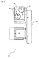
- Fig. 2 shows a drive unit for a conveyor of the device according to Fig. 1 ,
- Fig. 3 shows a holding device with two attached rotary encoders.
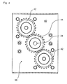
- Fig. 4 shows a gear ratio for driving the rotary encoder.
- Fig. 1 shows a typical application for the use of a rotary encoder. Shown is a device 10 for the treatment of bottles 12 in the beverage industry.
- the device 10 may represent a filling device, a transport device, a labeling machine, a packer, a palletizer or conveyor belts, as they are commonly used in beverage bottling.
- the apparatus 10 may also represent a stretch blow molder for making bottles or any other machine in which position sensing of the products present in the apparatus 10 and / or treated and / or conveyed plays an important role.
- the device 10 For position detection, the device 10 according to Fig. 1 an angular encoder 14 before. Furthermore, the device comprises an evaluation and control unit 16, which controls the transport of the bottles 12 through the device 10 by means of the rotary encoder 14. For this purpose, a device 10 associated with the control module 18, which receives signals from the evaluation and control unit 16.
- the rotary encoder 14 is normally connected to a stub shaft of a rotating shaft of one of the transport and / or conveyors, such as conveyor belt, the device 10, as shown in FIG FIGS. 2 to 4 is explained in more detail.
- the Fig. 2 shows a drive unit 20 for a conveyor of the device according to Fig. 1 ,
- the drive unit comprises an electric drive motor 22 which is coupled via a gear arrangement 24 to an output unit 26 which has a rotating shaft (cf. Fig. 3 ) of the device (cf. Fig. 1 ) drives.
- the schematic perspective view of Fig. 3 shows the holding device 28 with the two angular momentum sensors 14 attached thereto.
- the holding device is formed by a box-shaped holding plate 30, which with two sheet metal sections 32 on one side with the drive unit 26 (see. Fig. 2 ) is screwed.
- the gap between the two sheet metal sections 32 serves to pass the shaft 34, which is connected via a flexible shaft coupling 36 with a transmission gear 38 (see also Fig. 4 ).
- the two rotary encoder 14 are screwed.
- the shaft 34 may be, for example, the drive shaft of a conveyor belt.
- the transmission gear 38 serves to drive the two mounted on the front panel 40 rotary encoder 14 and includes a total of three straight-toothed gears 42 and 44.
- Each of the two rotary pulse generator 14 has a first gear 42 which is in each case with a second gear 44 in meshing engagement.
- the second gear 44 is rotatably connected to the shaft 34 via the shaft coupling 36, which serves to compensate for small axial offset or angular deviations, and forms part of the output unit 26. Since the gears 42 and 44 each have the same diameter is a 1: 1 translation of the two rotary pulse generator 14 ensures the same speed as the shaft speed.
- rotary pulse encoders 14 can be coupled to the shaft 34, for example also three or four.
- the holding device 28 may be modular and initially record only a rotary encoder 14, which can be supplemented as needed by another or several more rotary encoder, this should be useful or necessary at a later date.
Landscapes
- Physics & Mathematics (AREA)
- General Physics & Mathematics (AREA)
- Specific Conveyance Elements (AREA)
- Filling Of Jars Or Cans And Processes For Cleaning And Sealing Jars (AREA)
- Attitude Control For Articles On Conveyors (AREA)
Applications Claiming Priority (1)
| Application Number | Priority Date | Filing Date | Title |
|---|---|---|---|
| DE200820004480 DE202008004480U1 (de) | 2008-04-02 | 2008-04-02 | Halteeinrichtung für Drehimpulsgeber |
Publications (3)
| Publication Number | Publication Date |
|---|---|
| EP2107342A2 true EP2107342A2 (fr) | 2009-10-07 |
| EP2107342A3 EP2107342A3 (fr) | 2011-08-24 |
| EP2107342B1 EP2107342B1 (fr) | 2014-11-26 |
Family
ID=40586574
Family Applications (1)
| Application Number | Title | Priority Date | Filing Date |
|---|---|---|---|
| EP20090152770 Active EP2107342B1 (fr) | 2008-04-02 | 2009-02-13 | Dispositif de fixation avec générateur d'impulsions d'angle de rotation et des gammes de vitesse |
Country Status (2)
| Country | Link |
|---|---|
| EP (1) | EP2107342B1 (fr) |
| DE (1) | DE202008004480U1 (fr) |
Cited By (1)
| Publication number | Priority date | Publication date | Assignee | Title |
|---|---|---|---|---|
| CN105668137A (zh) * | 2016-03-23 | 2016-06-15 | 张素平 | 一种自动送料机输送带传动杆 |
Families Citing this family (1)
| Publication number | Priority date | Publication date | Assignee | Title |
|---|---|---|---|---|
| AT524982A1 (de) | 2021-04-09 | 2022-11-15 | Schiebel Antriebstechnik Gmbh | MT-Sensor |
Citations (6)
| Publication number | Priority date | Publication date | Assignee | Title |
|---|---|---|---|---|
| DE3046469A1 (de) | 1980-12-10 | 1982-07-15 | Ludwig Ing.(Grad.) 8751 Kleinwallstadt Jakob | Messgetriebe |
| DE19506938A1 (de) | 1995-02-28 | 1996-08-29 | Bosch Gmbh Robert | Verfahren und Vorrichtung zur Winkelmessung bei einem drehbaren Körper |
| DE19962241A1 (de) | 1999-12-22 | 2001-07-12 | Ruf Electronics Gmbh | Positionssensor |
| DE102004021928A1 (de) | 2004-05-04 | 2005-12-01 | Krones Ag | Prüfvorrichtung und Verfahren zur Prüfung der Funktionstüchtigkeit eines Drehimpulsgebers |
| US20060208726A1 (en) | 2005-03-21 | 2006-09-21 | Hr Textron, Inc. | Position sensing for moveable mechanical systems and associated methods and apparatus |
| DE102007025353A1 (de) | 2006-06-01 | 2007-12-06 | Harmonic Drive Systems Inc. | Untersetzungsgetriebeeinheit mit Drehstellungssensor |
Family Cites Families (4)
| Publication number | Priority date | Publication date | Assignee | Title |
|---|---|---|---|---|
| DE1945264A1 (de) * | 1969-09-06 | 1971-03-11 | Bhs Bayerische Berg | Elastische,drehmomentuebertragende Abstuetzung eines Zahnkranzes |
| ATE264225T1 (de) * | 1995-06-07 | 2004-04-15 | B & H Mfg Co Inc | Verfahren und vorrichtung zum anbringen von etiketten in blindenschrift auf gegenständen |
| JP4415859B2 (ja) * | 2005-01-12 | 2010-02-17 | パナソニック株式会社 | 回転角度検出装置 |
| DE102005035107A1 (de) * | 2005-07-27 | 2007-02-01 | Ebe Elektro-Bau-Elemente Gmbh | Mess- bzw. Gebervorrichtung |
-
2008
- 2008-04-02 DE DE200820004480 patent/DE202008004480U1/de not_active Expired - Lifetime
-
2009
- 2009-02-13 EP EP20090152770 patent/EP2107342B1/fr active Active
Patent Citations (6)
| Publication number | Priority date | Publication date | Assignee | Title |
|---|---|---|---|---|
| DE3046469A1 (de) | 1980-12-10 | 1982-07-15 | Ludwig Ing.(Grad.) 8751 Kleinwallstadt Jakob | Messgetriebe |
| DE19506938A1 (de) | 1995-02-28 | 1996-08-29 | Bosch Gmbh Robert | Verfahren und Vorrichtung zur Winkelmessung bei einem drehbaren Körper |
| DE19962241A1 (de) | 1999-12-22 | 2001-07-12 | Ruf Electronics Gmbh | Positionssensor |
| DE102004021928A1 (de) | 2004-05-04 | 2005-12-01 | Krones Ag | Prüfvorrichtung und Verfahren zur Prüfung der Funktionstüchtigkeit eines Drehimpulsgebers |
| US20060208726A1 (en) | 2005-03-21 | 2006-09-21 | Hr Textron, Inc. | Position sensing for moveable mechanical systems and associated methods and apparatus |
| DE102007025353A1 (de) | 2006-06-01 | 2007-12-06 | Harmonic Drive Systems Inc. | Untersetzungsgetriebeeinheit mit Drehstellungssensor |
Cited By (1)
| Publication number | Priority date | Publication date | Assignee | Title |
|---|---|---|---|---|
| CN105668137A (zh) * | 2016-03-23 | 2016-06-15 | 张素平 | 一种自动送料机输送带传动杆 |
Also Published As
| Publication number | Publication date |
|---|---|
| EP2107342A3 (fr) | 2011-08-24 |
| DE202008004480U1 (de) | 2009-08-13 |
| EP2107342B1 (fr) | 2014-11-26 |
Similar Documents
| Publication | Publication Date | Title |
|---|---|---|
| EP2018570B1 (fr) | Détermination de la vitesse de rotation d'un arbre de boîte de vitesses | |
| WO2014154378A1 (fr) | Machine rotative de traitement de récipients munie d'un codeur rotatif | |
| DE102013204461A1 (de) | Rundläufermaschine mit einem Karussell und Verfahren für eine Rundläufermaschine | |
| DE202015106176U1 (de) | Vorrichtung zum Einspannen von Bauteilen in einer Montagestraße | |
| EP3625522B1 (fr) | Appareil de mesure d'angle multitour | |
| DE102014107427A1 (de) | Vorrichtung und Verfahren zum gesteuerten Ausrichten und/oder gesteuerten Drehen von Behältern | |
| DE202022106926U1 (de) | Lenkbetätigungsvorrichtung für Fahrzeug | |
| DE102019115195A1 (de) | Vorrichtung zum Anpassen einer Führungsbreite einer Fördereinrichtung | |
| EP2519759B1 (fr) | Entraînement de réglage possédant des fonctions supplémentaires intégrées | |
| DE68915960T2 (de) | Getriebeanlage. | |
| EP2107342B1 (fr) | Dispositif de fixation avec générateur d'impulsions d'angle de rotation et des gammes de vitesse | |
| DE102006023286A1 (de) | Winkelsensor | |
| DE102013102202A1 (de) | Vorrichtung zur Positionierung und/oder Ausrichtung ein oder mehrerer verstellbarer Leitkomponenten zur Führung von Artikeln in einem Transportsystem | |
| DE102009041232A1 (de) | Drehgeber | |
| DE3781814T2 (de) | Registerkontrolle fuer kombinierte druck- und schneidmaschinen. | |
| EP2036712A2 (fr) | Dispositif de gaufrage rotatif et procédé de gaufrage | |
| DE202005020106U1 (de) | Getriebemotor | |
| EP1142000A1 (fr) | Dispositif de transport | |
| DE102014016592B4 (de) | Rotationsmaschine mit Statorverdrehsicherung | |
| DE102014221904A1 (de) | 1-Motor-Getriebeaktor für eine Kraftfahrzeuggetriebeeinrichtung | |
| DE2733353C2 (de) | Ausricht- und Verdrehstation für Nutenstanzautomaten | |
| DE19913492A1 (de) | Betätigungsvorrichtung | |
| DE2630433A1 (de) | Gleichlaufsteuerung fuer den antrieb zweier koaxialer kettenraeder an einer holzbearbeitungsmaschine | |
| DE1231595B (de) | Vorrichtung zur elektrischen Fernanzeige der Bewegungen des beweglichen Organs einer Maschine, insbesondere einer Werkzeugmaschine | |
| WO2007104426A1 (fr) | Dispositif d'affichage pour l'affichage analogique de grandeurs, de paramètres, etc. |
Legal Events
| Date | Code | Title | Description |
|---|---|---|---|
| PUAI | Public reference made under article 153(3) epc to a published international application that has entered the european phase |
Free format text: ORIGINAL CODE: 0009012 |
|
| AK | Designated contracting states |
Kind code of ref document: A2 Designated state(s): AT BE BG CH CY CZ DE DK EE ES FI FR GB GR HR HU IE IS IT LI LT LU LV MC MK MT NL NO PL PT RO SE SI SK TR |
|
| AX | Request for extension of the european patent |
Extension state: AL BA RS |
|
| PUAL | Search report despatched |
Free format text: ORIGINAL CODE: 0009013 |
|
| AK | Designated contracting states |
Kind code of ref document: A3 Designated state(s): AT BE BG CH CY CZ DE DK EE ES FI FR GB GR HR HU IE IS IT LI LT LU LV MC MK MT NL NO PL PT RO SE SI SK TR |
|
| AX | Request for extension of the european patent |
Extension state: AL BA RS |
|
| RIC1 | Information provided on ipc code assigned before grant |
Ipc: G01D 5/04 20060101AFI20110720BHEP |
|
| 17P | Request for examination filed |
Effective date: 20111115 |
|
| AKX | Designation fees paid |
Designated state(s): DE FR IT |
|
| 17Q | First examination report despatched |
Effective date: 20130930 |
|
| RIC1 | Information provided on ipc code assigned before grant |
Ipc: G01D 5/04 20060101AFI20140620BHEP |
|
| GRAP | Despatch of communication of intention to grant a patent |
Free format text: ORIGINAL CODE: EPIDOSNIGR1 |
|
| INTG | Intention to grant announced |
Effective date: 20140813 |
|
| RIN1 | Information on inventor provided before grant (corrected) |
Inventor name: SEGER, MARTIN Inventor name: HEIGL, STEFAN |
|
| GRAS | Grant fee paid |
Free format text: ORIGINAL CODE: EPIDOSNIGR3 |
|
| GRAA | (expected) grant |
Free format text: ORIGINAL CODE: 0009210 |
|
| AK | Designated contracting states |
Kind code of ref document: B1 Designated state(s): DE FR IT |
|
| REG | Reference to a national code |
Ref country code: DE Ref legal event code: R096 Ref document number: 502009010263 Country of ref document: DE Effective date: 20150108 |
|
| REG | Reference to a national code |
Ref country code: DE Ref legal event code: R097 Ref document number: 502009010263 Country of ref document: DE |
|
| PLBE | No opposition filed within time limit |
Free format text: ORIGINAL CODE: 0009261 |
|
| STAA | Information on the status of an ep patent application or granted ep patent |
Free format text: STATUS: NO OPPOSITION FILED WITHIN TIME LIMIT |
|
| 26N | No opposition filed |
Effective date: 20150827 |
|
| REG | Reference to a national code |
Ref country code: FR Ref legal event code: PLFP Year of fee payment: 8 |
|
| REG | Reference to a national code |
Ref country code: FR Ref legal event code: PLFP Year of fee payment: 9 |
|
| REG | Reference to a national code |
Ref country code: FR Ref legal event code: PLFP Year of fee payment: 10 |
|
| REG | Reference to a national code |
Ref country code: DE Ref legal event code: R082 Ref document number: 502009010263 Country of ref document: DE Representative=s name: BENNINGER, JOHANNES, DIPL.-ING., DE |
|
| PGFP | Annual fee paid to national office [announced via postgrant information from national office to epo] |
Ref country code: DE Payment date: 20241231 Year of fee payment: 17 |
|
| PGFP | Annual fee paid to national office [announced via postgrant information from national office to epo] |
Ref country code: IT Payment date: 20250110 Year of fee payment: 17 |
|
| PGFP | Annual fee paid to national office [announced via postgrant information from national office to epo] |
Ref country code: FR Payment date: 20251231 Year of fee payment: 18 |