EP2106934A1 - Agencement d'articulation pour suspension d'axe de moyeu - Google Patents
Agencement d'articulation pour suspension d'axe de moyeu Download PDFInfo
- Publication number
- EP2106934A1 EP2106934A1 EP08075231A EP08075231A EP2106934A1 EP 2106934 A1 EP2106934 A1 EP 2106934A1 EP 08075231 A EP08075231 A EP 08075231A EP 08075231 A EP08075231 A EP 08075231A EP 2106934 A1 EP2106934 A1 EP 2106934A1
- Authority
- EP
- European Patent Office
- Prior art keywords
- suspension arm
- vehicle
- tapering
- arrangement according
- hinging arrangement
- Prior art date
- Legal status (The legal status is an assumption and is not a legal conclusion. Google has not performed a legal analysis and makes no representation as to the accuracy of the status listed.)
- Granted
Links
Images


Classifications
-
- B—PERFORMING OPERATIONS; TRANSPORTING
- B60—VEHICLES IN GENERAL
- B60G—VEHICLE SUSPENSION ARRANGEMENTS
- B60G7/00—Pivoted suspension arms; Accessories thereof
- B60G7/02—Attaching arms to sprung part of vehicle
-
- B—PERFORMING OPERATIONS; TRANSPORTING
- B60—VEHICLES IN GENERAL
- B60G—VEHICLE SUSPENSION ARRANGEMENTS
- B60G11/00—Resilient suspensions characterised by arrangement, location or kind of springs
- B60G11/02—Resilient suspensions characterised by arrangement, location or kind of springs having leaf springs only
- B60G11/10—Resilient suspensions characterised by arrangement, location or kind of springs having leaf springs only characterised by means specially adapted for attaching the spring to axle or sprung part of the vehicle
- B60G11/12—Links, pins, or bushes
-
- B—PERFORMING OPERATIONS; TRANSPORTING
- B60—VEHICLES IN GENERAL
- B60G—VEHICLE SUSPENSION ARRANGEMENTS
- B60G11/00—Resilient suspensions characterised by arrangement, location or kind of springs
- B60G11/32—Resilient suspensions characterised by arrangement, location or kind of springs having springs of different kinds
- B60G11/34—Resilient suspensions characterised by arrangement, location or kind of springs having springs of different kinds including leaf springs
- B60G11/46—Resilient suspensions characterised by arrangement, location or kind of springs having springs of different kinds including leaf springs and also fluid springs
- B60G11/465—Resilient suspensions characterised by arrangement, location or kind of springs having springs of different kinds including leaf springs and also fluid springs with a flexible wall
-
- B—PERFORMING OPERATIONS; TRANSPORTING
- B60—VEHICLES IN GENERAL
- B60G—VEHICLE SUSPENSION ARRANGEMENTS
- B60G7/00—Pivoted suspension arms; Accessories thereof
- B60G7/001—Suspension arms, e.g. constructional features
-
- B—PERFORMING OPERATIONS; TRANSPORTING
- B60—VEHICLES IN GENERAL
- B60G—VEHICLE SUSPENSION ARRANGEMENTS
- B60G9/00—Resilient suspensions of a rigid axle or axle housing for two or more wheels
- B60G9/003—Resilient suspensions of a rigid axle or axle housing for two or more wheels the axle being rigidly connected to a trailing guiding device
-
- F—MECHANICAL ENGINEERING; LIGHTING; HEATING; WEAPONS; BLASTING
- F16—ENGINEERING ELEMENTS AND UNITS; GENERAL MEASURES FOR PRODUCING AND MAINTAINING EFFECTIVE FUNCTIONING OF MACHINES OR INSTALLATIONS; THERMAL INSULATION IN GENERAL
- F16F—SPRINGS; SHOCK-ABSORBERS; MEANS FOR DAMPING VIBRATION
- F16F1/00—Springs
- F16F1/36—Springs made of rubber or other material having high internal friction, e.g. thermoplastic elastomers
- F16F1/38—Springs made of rubber or other material having high internal friction, e.g. thermoplastic elastomers with a sleeve of elastic material between a rigid outer sleeve and a rigid inner sleeve or pin, i.e. bushing-type
- F16F1/393—Springs made of rubber or other material having high internal friction, e.g. thermoplastic elastomers with a sleeve of elastic material between a rigid outer sleeve and a rigid inner sleeve or pin, i.e. bushing-type with spherical or conical sleeves
-
- B—PERFORMING OPERATIONS; TRANSPORTING
- B60—VEHICLES IN GENERAL
- B60G—VEHICLE SUSPENSION ARRANGEMENTS
- B60G2200/00—Indexing codes relating to suspension types
- B60G2200/30—Rigid axle suspensions
- B60G2200/31—Rigid axle suspensions with two trailing arms rigidly connected to the axle
-
- B—PERFORMING OPERATIONS; TRANSPORTING
- B60—VEHICLES IN GENERAL
- B60G—VEHICLE SUSPENSION ARRANGEMENTS
- B60G2202/00—Indexing codes relating to the type of spring, damper or actuator
- B60G2202/10—Type of spring
- B60G2202/11—Leaf spring
- B60G2202/112—Leaf spring longitudinally arranged
-
- B—PERFORMING OPERATIONS; TRANSPORTING
- B60—VEHICLES IN GENERAL
- B60G—VEHICLE SUSPENSION ARRANGEMENTS
- B60G2202/00—Indexing codes relating to the type of spring, damper or actuator
- B60G2202/10—Type of spring
- B60G2202/15—Fluid spring
- B60G2202/152—Pneumatic spring
-
- B—PERFORMING OPERATIONS; TRANSPORTING
- B60—VEHICLES IN GENERAL
- B60G—VEHICLE SUSPENSION ARRANGEMENTS
- B60G2204/00—Indexing codes related to suspensions per se or to auxiliary parts
- B60G2204/10—Mounting of suspension elements
- B60G2204/12—Mounting of springs or dampers
- B60G2204/128—Damper mount on vehicle body or chassis
-
- B—PERFORMING OPERATIONS; TRANSPORTING
- B60—VEHICLES IN GENERAL
- B60G—VEHICLE SUSPENSION ARRANGEMENTS
- B60G2204/00—Indexing codes related to suspensions per se or to auxiliary parts
- B60G2204/10—Mounting of suspension elements
- B60G2204/12—Mounting of springs or dampers
- B60G2204/129—Damper mount on wheel suspension or knuckle
-
- B—PERFORMING OPERATIONS; TRANSPORTING
- B60—VEHICLES IN GENERAL
- B60G—VEHICLE SUSPENSION ARRANGEMENTS
- B60G2204/00—Indexing codes related to suspensions per se or to auxiliary parts
- B60G2204/10—Mounting of suspension elements
- B60G2204/14—Mounting of suspension arms
- B60G2204/143—Mounting of suspension arms on the vehicle body or chassis
-
- B—PERFORMING OPERATIONS; TRANSPORTING
- B60—VEHICLES IN GENERAL
- B60G—VEHICLE SUSPENSION ARRANGEMENTS
- B60G2204/00—Indexing codes related to suspensions per se or to auxiliary parts
- B60G2204/40—Auxiliary suspension parts; Adjustment of suspensions
- B60G2204/41—Elastic mounts, e.g. bushings
-
- B—PERFORMING OPERATIONS; TRANSPORTING
- B60—VEHICLES IN GENERAL
- B60G—VEHICLE SUSPENSION ARRANGEMENTS
- B60G2204/00—Indexing codes related to suspensions per se or to auxiliary parts
- B60G2204/40—Auxiliary suspension parts; Adjustment of suspensions
- B60G2204/43—Fittings, brackets or knuckles
- B60G2204/4302—Fittings, brackets or knuckles for fixing suspension arm on the vehicle body or chassis
-
- B—PERFORMING OPERATIONS; TRANSPORTING
- B60—VEHICLES IN GENERAL
- B60G—VEHICLE SUSPENSION ARRANGEMENTS
- B60G2204/00—Indexing codes related to suspensions per se or to auxiliary parts
- B60G2204/40—Auxiliary suspension parts; Adjustment of suspensions
- B60G2204/44—Centering or positioning means
- B60G2204/4402—Spacers or shims
-
- B—PERFORMING OPERATIONS; TRANSPORTING
- B60—VEHICLES IN GENERAL
- B60G—VEHICLE SUSPENSION ARRANGEMENTS
- B60G2206/00—Indexing codes related to the manufacturing of suspensions: constructional features, the materials used, procedures or tools
- B60G2206/01—Constructional features of suspension elements, e.g. arms, dampers, springs
- B60G2206/017—Constructional features of suspension elements, e.g. arms, dampers, springs forming an eye for the bushing
-
- B—PERFORMING OPERATIONS; TRANSPORTING
- B60—VEHICLES IN GENERAL
- B60G—VEHICLE SUSPENSION ARRANGEMENTS
- B60G2206/00—Indexing codes related to the manufacturing of suspensions: constructional features, the materials used, procedures or tools
- B60G2206/01—Constructional features of suspension elements, e.g. arms, dampers, springs
- B60G2206/10—Constructional features of arms
- B60G2206/15—Constructional features of arms the arm being resilient
-
- B—PERFORMING OPERATIONS; TRANSPORTING
- B60—VEHICLES IN GENERAL
- B60G—VEHICLE SUSPENSION ARRANGEMENTS
- B60G2206/00—Indexing codes related to the manufacturing of suspensions: constructional features, the materials used, procedures or tools
- B60G2206/01—Constructional features of suspension elements, e.g. arms, dampers, springs
- B60G2206/60—Subframe construction
- B60G2206/601—Hanger bracket
-
- B—PERFORMING OPERATIONS; TRANSPORTING
- B60—VEHICLES IN GENERAL
- B60G—VEHICLE SUSPENSION ARRANGEMENTS
- B60G2206/00—Indexing codes related to the manufacturing of suspensions: constructional features, the materials used, procedures or tools
- B60G2206/01—Constructional features of suspension elements, e.g. arms, dampers, springs
- B60G2206/70—Materials used in suspensions
- B60G2206/72—Steel
- B60G2206/722—Plates
-
- B—PERFORMING OPERATIONS; TRANSPORTING
- B60—VEHICLES IN GENERAL
- B60G—VEHICLE SUSPENSION ARRANGEMENTS
- B60G2206/00—Indexing codes related to the manufacturing of suspensions: constructional features, the materials used, procedures or tools
- B60G2206/01—Constructional features of suspension elements, e.g. arms, dampers, springs
- B60G2206/70—Materials used in suspensions
- B60G2206/73—Rubber; Elastomers
-
- B—PERFORMING OPERATIONS; TRANSPORTING
- B60—VEHICLES IN GENERAL
- B60G—VEHICLE SUSPENSION ARRANGEMENTS
- B60G2206/00—Indexing codes related to the manufacturing of suspensions: constructional features, the materials used, procedures or tools
- B60G2206/01—Constructional features of suspension elements, e.g. arms, dampers, springs
- B60G2206/80—Manufacturing procedures
- B60G2206/81—Shaping
- B60G2206/8102—Shaping by stamping
- B60G2206/81022—Shaping by stamping by forging
-
- B—PERFORMING OPERATIONS; TRANSPORTING
- B60—VEHICLES IN GENERAL
- B60G—VEHICLE SUSPENSION ARRANGEMENTS
- B60G2206/00—Indexing codes related to the manufacturing of suspensions: constructional features, the materials used, procedures or tools
- B60G2206/01—Constructional features of suspension elements, e.g. arms, dampers, springs
- B60G2206/80—Manufacturing procedures
- B60G2206/81—Shaping
- B60G2206/8106—Shaping by thermal treatment, e.g. curing hardening, vulcanisation
-
- B—PERFORMING OPERATIONS; TRANSPORTING
- B60—VEHICLES IN GENERAL
- B60G—VEHICLE SUSPENSION ARRANGEMENTS
- B60G2206/00—Indexing codes related to the manufacturing of suspensions: constructional features, the materials used, procedures or tools
- B60G2206/01—Constructional features of suspension elements, e.g. arms, dampers, springs
- B60G2206/80—Manufacturing procedures
- B60G2206/82—Joining
- B60G2206/8205—Joining by conical or compressed rubber clamping inserts as joining means
-
- F—MECHANICAL ENGINEERING; LIGHTING; HEATING; WEAPONS; BLASTING
- F16—ENGINEERING ELEMENTS AND UNITS; GENERAL MEASURES FOR PRODUCING AND MAINTAINING EFFECTIVE FUNCTIONING OF MACHINES OR INSTALLATIONS; THERMAL INSULATION IN GENERAL
- F16F—SPRINGS; SHOCK-ABSORBERS; MEANS FOR DAMPING VIBRATION
- F16F1/00—Springs
- F16F1/02—Springs made of steel or other material having low internal friction; Wound, torsion, leaf, cup, ring or the like springs, the material of the spring not being relevant
- F16F1/18—Leaf springs
- F16F1/26—Attachments or mountings
- F16F1/30—Attachments or mountings comprising intermediate pieces made of rubber or similar elastic material
-
- Y—GENERAL TAGGING OF NEW TECHNOLOGICAL DEVELOPMENTS; GENERAL TAGGING OF CROSS-SECTIONAL TECHNOLOGIES SPANNING OVER SEVERAL SECTIONS OF THE IPC; TECHNICAL SUBJECTS COVERED BY FORMER USPC CROSS-REFERENCE ART COLLECTIONS [XRACs] AND DIGESTS
- Y10—TECHNICAL SUBJECTS COVERED BY FORMER USPC
- Y10T—TECHNICAL SUBJECTS COVERED BY FORMER US CLASSIFICATION
- Y10T403/00—Joints and connections
- Y10T403/32—Articulated members
- Y10T403/32606—Pivoted
- Y10T403/32861—T-pivot, e.g., wrist pin, etc.
- Y10T403/32893—T-pivot, e.g., wrist pin, etc. including distinct pin retainer
- Y10T403/32909—Threaded pin end
Definitions
- the present invention relates to a hinging arrangement for a wheel axle suspension of a vehicle, comprising an attachment eye fixed to a component to be hingedly attached to the vehicle, and a hinge pin, e.g. a hinge bolt, attached to a fixed vehicle component, which hinge pin is extending through the attachment eye.
- a hinge pin e.g. a hinge bolt
- Such hinging arrangements are known, for instance for hingedly attaching a front end portion of a suspension arm to a bearing bracket which is attached to a vehicle chassis.
- the known hinging arrangements have a cilindrical metal bushing which is clamped between the side plates of the bearing bracket.
- a cilindrical rubber bushing Surrounding the metal bushing is arranged a cilindrical rubber bushing which engages the inner side of the attachment eye and allows a rotational movement of the suspension arm around the hinging pin.
- the invention has for an object to provide an alternative hinging arrangement for a wheel axle suspension.
- tapping bore portion as meant in this application is meant a bore portion having a first end and a second end, wherein the bore at the first end has a larger diameter than at the second end, and wherein the diameter of the bore portion is continuously decreasing from the first end towards the second end.
- This tapering shape could be a conical shape, but could also be a spherical shape.
- the hinging arrangement according to the invention can advantageously be incorporated in a suspension for a vehicle, comprising a longitudinal suspension arm to which the axle is fixed, a bearing bracket fixed to the vehicle chassis and an air spring bearing against the vehicle chassis, wherein the suspension arm, seen in the driving direction of the vehicle, on its rear end is attached to the air spring and on its front end is hingedly attached to the bearing bracket.
- the suspension arm is a resilient member.
- the hinging arrangement according to the invention is then able to support the suspension arm in all directions. The hinging arrangement absorbs forces in rotation direction by a hinging action, which hinging action is due to springing action of the suspension arm.
- the hinging arrangement is able to absorb forces in transverse direction, horizontal forces due to braking action on the wheels of the vehicle, and vertical direction which are due to loads on the axle and roll movements. Also occurs an absorbtion of torsion, which is due to roll movement of the vehicle.
- An advantage is that due to the tapering shape the eye can be made by forging more easily without the need to machine the eye afterwards in order to callibrate the bore.
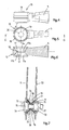
- Fig. 1 shows one side of a wheel axle suspension of a vehicle, e.g. of a trailer.
- the wheel axle 1, on which one or more wheels are arranged at both ends, is illustrated as a hollow round axle. However, the wheel axle 1 may also be square or have some other cross section.
- the wheel axle suspension shown in Fig. 1 comprises a carrying bracket 3 which is attached to the chassis of a vehicle, which is illustrated highly diagrammatically in Fig. 1 and indicated by the reference numeral 2.
- a suspension arm 5, which extends in the longitudinal direction of the vehicle, is hingedly attached to the carrying bracket 3 by a hinging arrangement 4.
- a pneumatic spring 7 is arranged between the free rear end portion 6 of the suspension arm 5, situated at a distance from the hinging arrangement 4, and the chassis 2.
- a shock absorber 8 fitted between the carrying bracket 3 and the suspension arm 5.
- the wheel axle 1 is fixed to the suspension arm 5 in a manner known per se, by means of an axle pad 10 arranged against the suspension arm 5 and forming a seat for the axle 1 and U-shaped bolts 9, with which the suspension arm 5, the axle pad 10 and the axle 1 are clamped together.
- the suspension arm 5 is fastened to the support bracket 3 by means of a hinging bolt 11.
- the support bracket 3 comprises two side plates 12 and 13, and the support bracket 3 is open towards the rear, as seen in the direction of travel.
- the hinging bolt 11 extends in the transverse direction through the support bracket 3 and fits through holes 14 in the side plates 11 and 12 of the support bracket 3.
- the holes 14 are designed as slots which extend substantially in the direction of the longitudinal suspension arm 5, such that the hinge bolt position can be adjusted and the suspension arms supporting the same axle can be aligned.
- the suspension arm 5 is provided on its front end portion with an attachment eye 15, which is shown in more detail in Figs. 4 - 6 .
- the attachment eye 15 has a passage for the hinge bolt 11, said passage comprising a central bore 16 and two opposing tapering bore portions 17.
- the tapering bore portions 17 have an outer end 17a and an inner end 17b, wherein the outer end 17a has a larger diameter than the inner end 17b.
- the radially inwardly facing surface 17c of the tapering bore portion 17 is tapering from the outer end towards the inner end 17b.
- the diameter of the tapering bore portion 17 is thus continuously decreasing from the outer end 17a towards the inner end 17b.
- the central bore 16 has a constant diameter and connects the inner ends 17b of the respective tapering bore portions 17.
- the hinging arrangement 4 further comprises a resilient ring 18, preferably made of rubber or another suitable elastomeric material.
- the rubber ring 18 is received within each of the tapering bore portions 17, as can be seen in Fig. 2 .
- Said rubber ring 18 bears with one side against the tapering surface 17c of the tapering bore portion 17.
- a conical clamping member 19 In each of the tapering bore portions 17 is provided a conical clamping member 19.
- the clamping member 19 is provided with a central bore 20 for the hinge bolt 11.
- the clamping member 19 has a conical outer surface 19c that faces the tapering surface 17c of the tapering bore portion 17. In the mounted state, the clamping member 19 and the surface are clamped towards eachother by means of the hinging bolt 11 and a nut 21, compressing between them the resilient ring 18.
- the resilient ring 18, which is preferably made of rubber is preferably vulcanized on the conical surface of the clamping member 19.
- a distance bushing 22 In the central bore 16, between the inner ends of the clamping members 19 facing each other, is arranged a distance bushing 22.
- the hinging arrangement of the suspension arm 5 is mounted as follows: In the attachment eye 15 of the suspension arm 5 are inserted the distance bushing 22 in the central bore 16 and the clamping members 19 with a rubber ring 18 vulcanized on their conical surface are inserted in each of the tapering bore portions 17. Adjustment brackets 23, which are know per se, e.g. from EP 943 529 are arranged on the side plates 12, 13 of the bearing bracket 3. Then the eye 15 of the suspension arm is inserted between the side plates 12, 13 of the bearing bracket 3. Next, the hinging bolt is inserted through the adjustment brackets , the side plates 12 and 13, the bores 20 of the clamping members 19, and through the bushing 22. This assembly is clamped together by means of tensioning the bolt 11 and nut 21 assembly.
- the resilience of the rubber rings 18 provides a limited freedom of movement of the suspension arm in the rotational direction. Also a limited freedom in tranverse direction, i.e. axial direction of the bolt 11 and directions perpendicular thereto is provided by the resilient ring 18. Tensioning the metal parts against each other by means of the bolt 11 and nut 21 biases the rubber ring 18 which thereby obtains a long duration of life.
- Fig. 7 is shown an alternative embodiment of the hinging arrangement for the suspension arm 5.
- the attachment eye 15 at the front end portion of the suspension arm 5 is similar to the one described above.
- the bearing bracket has substantially parallel side plates 71, 72 in which inwardly projecting dents 73 are provided in the region around the holes for the hinging bolt 11.
- the holes for the hinging bolt are preferably slotted holes, such that the hinge bolt 11, and therewith the suspension arms for the axle can be aligned.
- the dents 73 have a tapering side wall 74.
- the inner side of the dent 73 is received in the tapering bore portion 17 of the eye 15.
- clamping members 75 are received.
- the clamping members 75 have basically a frusto-conical shape of which the conical surface bears against the tapering surface of the dent.
- a spacer bushing 76 is located between the inner ends 77 of the opposing dents 73.
- On the inner side of the conical surface of the dents 73 is provided a dish shaped metal ring 77 on which a rubber ring 78 is vulcanized.
- the rubber ring 78 is bearing against the tapering surface of the tapering bore portion 17.
- the hinging bolt 11 passes through the clamping members 75, the side plates 71, 72, and the bushing 76. By tensioning the nut 21 on the bolt 11, the hinging arrangement is fixed.
- Fig. 8 a cross section through an asymetrical attachment eye 80 of a suspension arm.
- the eye 80 is attached to a bearing bracket comprising one single side plate 81.
- the eye comprises a conical bore 82 which tapers from the end remote from the side plate 81 towards the end near the side plate 81.
- a flat rubber ring 83 Between the side of the eye facing the side plate 81 and the side plate 81 is located a flat rubber ring 83.
- a rubber ring 84 In the tapering bore 82 is received a rubber ring 84.
- a spacer bushing 85 which bears with one end against the side plate 81 and a clamping member 86 with a conical outer surface and a bore for the shaft of a hinging bolt 11.
- the eye 80 of the suspension arm is clamped against the side plate 81 by means of the hinging bolt 11 and the nut 21.
- the rubber rings 83 and 84 provide some degree of freedom of movement in rotational direction around the central axis
- Fig. 9A is shown a cross sectional view of a hinging arrangement according to the invention, wherein the bearing bracket comprises one single side plate 91.
- the attachment eye 90 of the suspension arm (cf. Fig. 9B ) is symmetrical and has a relatively small width. It has a bore with a cilindrical central bore portion 92 and two opposing tapering bore portions 93.
- Two rubber rings 94 are inserted from opposite sides into the bore.
- the rubber rings 94 have a relatively flat base portion 94b and a frusto-conical portion 94a protruding from the base portion 94b.
- the frusto-conical portion 94a is received in the tapering bore portion 93 of the eye 90.
- the top sides of the frusto-conical portions 94a may abut each other in the central bore portion 92.
- the base portions 94b engage on the side surface of the eye 90.
- a spacer bushing 95 preferably of metal, extends through the central holes of the rubber rings 94 and abuts with one end the side plate 91 of the bearing bracket. On the other end of the spacer bushing 95 engages a clamping member 96. The whole assembly is clamped together by the hinge bolt 11 cooperating with the nut 21.
- bearing brackets with one single side plate 81, 91 as shown in Figs. 8 and 9 could be provided with a dent surrounding the, preferably slotted, hole for the hinging bolt 11, as is shown in Fig. 7 .
- Fig. 10 is shown a partly sectional view, partly elevational view of a hinging arrangement according to the invention, wherein the attachment eye 100 has a circular cross section.
- the bore through the eye 100 thus has a tapering surface which narrows towards the center along a convex curve.
- the clamping members 101 have a curved outer surface and abut each other with their inner ends.
- a rubber ring 102 Between each of the clamping members 101 and the tapring surface of the eye 100 is arranged a rubber ring 102.
- Said ring 102 has a thicknes that increases from the radially inner side of the ring 102 towards the radially outer side.
- Fig. 11 is shown a cross sectional view of an attachment eye 110 with a drop shaped cross section.
- the bore through the eye 110 thus has two tapering opposing bore portions.
- a rubber ring 112 with a frusto-conical shape.
- the rubber rings 112 abut each other at the center.
- the rubber rings 112 have a central passage 113 through which a spacer bushing of metal extends.
- a clamping member 115 On the outer end of each of the rubber rings 112 engages a clamping member 115 in this case configured as a metal ring.
- the assembly is clamped together in a similar way as described for the previously described embodiments by means of a bolt and a nut.
- This embodiment of Fig. 11 is particularly suitable, but not limited, for hingedly attaching a shock absorber of a vehicle suspension.
Landscapes
- Engineering & Computer Science (AREA)
- Mechanical Engineering (AREA)
- General Engineering & Computer Science (AREA)
- Vehicle Body Suspensions (AREA)
Priority Applications (8)
| Application Number | Priority Date | Filing Date | Title |
|---|---|---|---|
| EP08075231A EP2106934B1 (fr) | 2008-03-31 | 2008-03-31 | Agencement d'articulation pour suspension d'axe de moyeu |
| CA2718410A CA2718410A1 (fr) | 2008-03-31 | 2009-03-06 | Dispositif d'articulation pour une suspension d'essieu de roue |
| US12/935,050 US8448964B2 (en) | 2008-03-31 | 2009-03-06 | Hinging arrangement for a wheel axle suspension |
| PCT/NL2009/000054 WO2009123437A1 (fr) | 2008-03-31 | 2009-03-06 | Dispositif d’articulation pour une suspension d'essieu de roue |
| BRPI0909444A BRPI0909444A2 (pt) | 2008-03-31 | 2009-03-06 | dispositivo de articulação para suspensão de eixo de roda de um veículo, suspensão de eixo de roda para um veículo, e, braço de suspensão. |
| AU2009232533A AU2009232533A1 (en) | 2008-03-31 | 2009-03-06 | Hinging arrangement for a wheel axle suspension |
| CN2009801102090A CN101977785B (zh) | 2008-03-31 | 2009-03-06 | 用于轮轴悬架的铰接装置 |
| ZA2010/07393A ZA201007393B (en) | 2008-03-31 | 2010-10-15 | Hinging arrangement for a wheel axle suspension |
Applications Claiming Priority (1)
| Application Number | Priority Date | Filing Date | Title |
|---|---|---|---|
| EP08075231A EP2106934B1 (fr) | 2008-03-31 | 2008-03-31 | Agencement d'articulation pour suspension d'axe de moyeu |
Publications (2)
| Publication Number | Publication Date |
|---|---|
| EP2106934A1 true EP2106934A1 (fr) | 2009-10-07 |
| EP2106934B1 EP2106934B1 (fr) | 2013-03-06 |
Family
ID=39731725
Family Applications (1)
| Application Number | Title | Priority Date | Filing Date |
|---|---|---|---|
| EP08075231A Not-in-force EP2106934B1 (fr) | 2008-03-31 | 2008-03-31 | Agencement d'articulation pour suspension d'axe de moyeu |
Country Status (8)
| Country | Link |
|---|---|
| US (1) | US8448964B2 (fr) |
| EP (1) | EP2106934B1 (fr) |
| CN (1) | CN101977785B (fr) |
| AU (1) | AU2009232533A1 (fr) |
| BR (1) | BRPI0909444A2 (fr) |
| CA (1) | CA2718410A1 (fr) |
| WO (1) | WO2009123437A1 (fr) |
| ZA (1) | ZA201007393B (fr) |
Cited By (6)
| Publication number | Priority date | Publication date | Assignee | Title |
|---|---|---|---|---|
| WO2011119020A1 (fr) * | 2010-03-25 | 2011-09-29 | Weweler Nederland B.V. | Support de montage de bras oscillant |
| CN102205780A (zh) * | 2010-03-29 | 2011-10-05 | 现代自动车株式会社 | 主动几何控制悬架系统以及驱动该系统的致动设备 |
| EP2423010A3 (fr) * | 2010-08-31 | 2012-04-11 | BPW Bergische Achsen KG | Guide d'essieu de véhicule et douille en caoutchouc d'acier pour l'utilisation dans un volant de véhicule |
| CN102416832A (zh) * | 2010-09-24 | 2012-04-18 | 许布奈有限公司 | 铰接式车辆的铰接装置 |
| US9132860B2 (en) | 2012-11-30 | 2015-09-15 | HÜBNER GmbH & Co. KG | Articulated vehicle with a joint between the vehicle parts |
| WO2017118771A1 (fr) * | 2016-01-04 | 2017-07-13 | Fundiciones De Vera, S.A. | Procédé de fabrication de profilés pour ressorts à lames |
Families Citing this family (9)
| Publication number | Priority date | Publication date | Assignee | Title |
|---|---|---|---|---|
| CN102753371B (zh) * | 2010-02-15 | 2016-11-23 | 沃尔沃卡车集团 | 用于机动车辆的悬架组件和包括该悬架组件的机动车辆 |
| US20140191486A1 (en) * | 2013-01-10 | 2014-07-10 | Hendrickson Usa, L.L.C. | Multi-tapered suspension component |
| DE102013203848A1 (de) * | 2013-03-07 | 2014-09-11 | Zf Friedrichshafen Ag | Antriebsachse für ein Flurförderzeug |
| US9447900B2 (en) * | 2013-05-16 | 2016-09-20 | Mueller International, Llc | Non-conductive roller assembly |
| DE102013218701B3 (de) * | 2013-09-18 | 2015-01-08 | Ford Global Technologies, Llc | Verbundlenkerachse für ein Fahrzeug sowie Lageranordnung für eine Verbundlenkerachse |
| JP6380211B2 (ja) * | 2015-04-02 | 2018-08-29 | トヨタ自動車株式会社 | 車両のサスペンション |
| DE102019202306A1 (de) * | 2019-02-20 | 2020-08-20 | Thyssenkrupp Ag | Stabilisatorschelle, Stabilisator-Stabilisatorschellen-Anordnung und Verfahren zum Herstellen einer Stabilisatorschelle |
| JP7424762B2 (ja) * | 2019-06-25 | 2024-01-30 | 日本発條株式会社 | 懸架装置 |
| CN111099523B (zh) * | 2020-01-15 | 2021-09-10 | 岳西县盛宏工贸有限责任公司 | 一种叉车门架倾斜缸活塞杆端部安装支座及其锻压工艺 |
Citations (21)
| Publication number | Priority date | Publication date | Assignee | Title |
|---|---|---|---|---|
| DD23979A (fr) * | ||||
| GB257009A (en) | 1925-05-19 | 1926-08-19 | Frank Smith | Improvements in attaching devices for motor vehicle shock-absorbers |
| US1931945A (en) | 1931-03-30 | 1933-10-24 | Oscar U Zerk | Spring eye joint |
| US2308967A (en) | 1941-03-01 | 1943-01-19 | Firestone Tire & Rubber Co | Bushing |
| US2477447A (en) * | 1943-08-16 | 1949-07-26 | Thomas L Fawick | Flexible coupling |
| US2621949A (en) | 1947-03-15 | 1952-12-16 | Metalaslik Ltd | Resilient bush |
| US2900182A (en) | 1955-04-27 | 1959-08-18 | William L Hinks | Static load bearings |
| US3493222A (en) | 1967-10-30 | 1970-02-03 | Fruehauf Corp | Spring suspension |
| FR2162838A5 (fr) | 1971-11-24 | 1973-07-20 | Nissan Motor | |
| US4175806A (en) | 1977-04-06 | 1979-11-27 | Taylor Gordon J | Radius rod or rocker arm bushes |
| US4595216A (en) * | 1984-07-20 | 1986-06-17 | Lear Siegler, Inc. | Vehicle suspension structure |
| EP0504593A1 (fr) * | 1991-03-20 | 1992-09-23 | Bergische Achsenfabrik Fr. Kotz & Söhne | Dispositif d'ajustage |
| US5193787A (en) * | 1991-05-03 | 1993-03-16 | Maremont Corporation | Sleeve and bushing assembly and method of manufacturing the same |
| US5337997A (en) * | 1991-12-16 | 1994-08-16 | Hockney Pty Ltd. | Extruded aluminum spring hanger |
| EP0615869A2 (fr) * | 1993-03-17 | 1994-09-21 | Steyr Nutzfahrzeuge Ag | Support pour une fixation sans entretien de l'oeillet d'un ressort à lame dans des voitures automobiles, notamment des véhicules utilitaires |
| US5362095A (en) | 1991-07-25 | 1994-11-08 | Nicholas Eveley | Resiliently mounted cantilever spring supported air spring suspension |
| FR2737443A1 (fr) | 1995-08-01 | 1997-02-07 | Europ Semi Remorques | Main de suspension pour un essieu de vehicule industriel et vehicule industriel l'incorporant |
| EP0943529A1 (fr) * | 1998-03-17 | 1999-09-22 | Weweler Nederland B.V. | Dispositif de fixation pour un bras de support longitudinal d'un ensemble d' essieu suspendu de véhicule |
| WO2003072377A1 (fr) | 2002-02-28 | 2003-09-04 | Volvo Lastvagnar Ab | Palier de support conique |
| EP1459914A1 (fr) | 2003-03-17 | 2004-09-22 | Weweler Nederland B.V. | Fixation d'un support de palier d'un ensemble-essieu au châssis d'un véhicule |
| EP1728654A1 (fr) | 2005-06-03 | 2006-12-06 | Meritor Heavy Vehicle Systems Limited | Suspension à bras tirés |
Family Cites Families (9)
| Publication number | Priority date | Publication date | Assignee | Title |
|---|---|---|---|---|
| DE23979C (de) | TH. A. EDISON in Menlo-Park, New-Jersey (V. St. A.) | Neuerungen in den Mitteln zur Regulirung der Stromstärken dynamo- oder magnetoelektrischer Maschinen | ||
| US2732267A (en) * | 1956-01-24 | acotvtotv | ||
| US2853325A (en) * | 1955-10-21 | 1958-09-23 | Alaska Juneau Gold Mining Comp | Resilient bearings for relatively rotatable members |
| US3580347A (en) * | 1967-12-13 | 1971-05-25 | Dura Corp | Tapered spring leaf suspension for driver tandem axle assembly |
| US4880319A (en) * | 1986-05-05 | 1989-11-14 | The B. F. Goodrich Company | Bearing assembly |
| NZ221163A (en) * | 1988-01-22 | 1991-07-26 | Bruce Archibald Short | Tapered resilient bush for vehicle suspension arm |
| GB8805124D0 (en) * | 1988-03-03 | 1988-03-30 | Blair George Plc | Improved self-adjusting bearing |
| US5189962A (en) * | 1988-09-01 | 1993-03-02 | Kawasaki Jukogyo Kabushiki Kaisha | Axle box suspension with resilient elements adhered to the movable components such that all relative movement between the components occurs by deformation of the resilient elements |
| US5372373A (en) * | 1993-06-11 | 1994-12-13 | Reel; Milton M. | Axle pivot assembly |
-
2008
- 2008-03-31 EP EP08075231A patent/EP2106934B1/fr not_active Not-in-force
-
2009
- 2009-03-06 BR BRPI0909444A patent/BRPI0909444A2/pt not_active Application Discontinuation
- 2009-03-06 AU AU2009232533A patent/AU2009232533A1/en not_active Abandoned
- 2009-03-06 WO PCT/NL2009/000054 patent/WO2009123437A1/fr active Application Filing
- 2009-03-06 US US12/935,050 patent/US8448964B2/en not_active Expired - Fee Related
- 2009-03-06 CA CA2718410A patent/CA2718410A1/fr not_active Abandoned
- 2009-03-06 CN CN2009801102090A patent/CN101977785B/zh not_active Expired - Fee Related
-
2010
- 2010-10-15 ZA ZA2010/07393A patent/ZA201007393B/en unknown
Patent Citations (21)
| Publication number | Priority date | Publication date | Assignee | Title |
|---|---|---|---|---|
| DD23979A (fr) * | ||||
| GB257009A (en) | 1925-05-19 | 1926-08-19 | Frank Smith | Improvements in attaching devices for motor vehicle shock-absorbers |
| US1931945A (en) | 1931-03-30 | 1933-10-24 | Oscar U Zerk | Spring eye joint |
| US2308967A (en) | 1941-03-01 | 1943-01-19 | Firestone Tire & Rubber Co | Bushing |
| US2477447A (en) * | 1943-08-16 | 1949-07-26 | Thomas L Fawick | Flexible coupling |
| US2621949A (en) | 1947-03-15 | 1952-12-16 | Metalaslik Ltd | Resilient bush |
| US2900182A (en) | 1955-04-27 | 1959-08-18 | William L Hinks | Static load bearings |
| US3493222A (en) | 1967-10-30 | 1970-02-03 | Fruehauf Corp | Spring suspension |
| FR2162838A5 (fr) | 1971-11-24 | 1973-07-20 | Nissan Motor | |
| US4175806A (en) | 1977-04-06 | 1979-11-27 | Taylor Gordon J | Radius rod or rocker arm bushes |
| US4595216A (en) * | 1984-07-20 | 1986-06-17 | Lear Siegler, Inc. | Vehicle suspension structure |
| EP0504593A1 (fr) * | 1991-03-20 | 1992-09-23 | Bergische Achsenfabrik Fr. Kotz & Söhne | Dispositif d'ajustage |
| US5193787A (en) * | 1991-05-03 | 1993-03-16 | Maremont Corporation | Sleeve and bushing assembly and method of manufacturing the same |
| US5362095A (en) | 1991-07-25 | 1994-11-08 | Nicholas Eveley | Resiliently mounted cantilever spring supported air spring suspension |
| US5337997A (en) * | 1991-12-16 | 1994-08-16 | Hockney Pty Ltd. | Extruded aluminum spring hanger |
| EP0615869A2 (fr) * | 1993-03-17 | 1994-09-21 | Steyr Nutzfahrzeuge Ag | Support pour une fixation sans entretien de l'oeillet d'un ressort à lame dans des voitures automobiles, notamment des véhicules utilitaires |
| FR2737443A1 (fr) | 1995-08-01 | 1997-02-07 | Europ Semi Remorques | Main de suspension pour un essieu de vehicule industriel et vehicule industriel l'incorporant |
| EP0943529A1 (fr) * | 1998-03-17 | 1999-09-22 | Weweler Nederland B.V. | Dispositif de fixation pour un bras de support longitudinal d'un ensemble d' essieu suspendu de véhicule |
| WO2003072377A1 (fr) | 2002-02-28 | 2003-09-04 | Volvo Lastvagnar Ab | Palier de support conique |
| EP1459914A1 (fr) | 2003-03-17 | 2004-09-22 | Weweler Nederland B.V. | Fixation d'un support de palier d'un ensemble-essieu au châssis d'un véhicule |
| EP1728654A1 (fr) | 2005-06-03 | 2006-12-06 | Meritor Heavy Vehicle Systems Limited | Suspension à bras tirés |
Cited By (9)
| Publication number | Priority date | Publication date | Assignee | Title |
|---|---|---|---|---|
| WO2011119020A1 (fr) * | 2010-03-25 | 2011-09-29 | Weweler Nederland B.V. | Support de montage de bras oscillant |
| US8960694B2 (en) | 2010-03-25 | 2015-02-24 | Vdl Weweler B.V. | Trailing arm mounting bracket |
| CN102205780A (zh) * | 2010-03-29 | 2011-10-05 | 现代自动车株式会社 | 主动几何控制悬架系统以及驱动该系统的致动设备 |
| CN102205780B (zh) * | 2010-03-29 | 2014-10-08 | 现代自动车株式会社 | 主动几何控制悬架系统以及驱动该系统的致动设备 |
| EP2423010A3 (fr) * | 2010-08-31 | 2012-04-11 | BPW Bergische Achsen KG | Guide d'essieu de véhicule et douille en caoutchouc d'acier pour l'utilisation dans un volant de véhicule |
| CN102416832A (zh) * | 2010-09-24 | 2012-04-18 | 许布奈有限公司 | 铰接式车辆的铰接装置 |
| CN102416832B (zh) * | 2010-09-24 | 2014-07-30 | 许布奈有限公司 | 铰接式车辆的铰接装置 |
| US9132860B2 (en) | 2012-11-30 | 2015-09-15 | HÜBNER GmbH & Co. KG | Articulated vehicle with a joint between the vehicle parts |
| WO2017118771A1 (fr) * | 2016-01-04 | 2017-07-13 | Fundiciones De Vera, S.A. | Procédé de fabrication de profilés pour ressorts à lames |
Also Published As
| Publication number | Publication date |
|---|---|
| CA2718410A1 (fr) | 2009-10-08 |
| WO2009123437A1 (fr) | 2009-10-08 |
| EP2106934B1 (fr) | 2013-03-06 |
| CN101977785B (zh) | 2013-03-27 |
| US8448964B2 (en) | 2013-05-28 |
| ZA201007393B (en) | 2012-01-25 |
| BRPI0909444A2 (pt) | 2015-12-01 |
| US20110018217A1 (en) | 2011-01-27 |
| CN101977785A (zh) | 2011-02-16 |
| AU2009232533A1 (en) | 2009-10-08 |
Similar Documents
| Publication | Publication Date | Title |
|---|---|---|
| EP2106934A1 (fr) | Agencement d'articulation pour suspension d'axe de moyeu | |
| US9855810B2 (en) | Multi-tapered suspension component | |
| US7722065B2 (en) | Composite spring with resilient attachment interface | |
| EP2809532B1 (fr) | Suspension de véhicule comprenant un ensemble ressort à lames léger | |
| US20090243247A1 (en) | Suspension system structure and method of assembly | |
| EP3019359A1 (fr) | Suspension de véhicule et ressort à lames s'y rapportant | |
| US20110057371A1 (en) | Suspension Mechanism | |
| US20050001366A1 (en) | Conical rubber bearing | |
| US10500913B1 (en) | Shock absorbing equalizer for suspension system | |
| US10703155B2 (en) | Multi-functional suspension bushing | |
| RU76087U1 (ru) | Штанга реактивная с резинометаллическими шарнирами (варианты) | |
| EP1052123A1 (fr) | Ensemble de fixation d'essieu et bras de suspension comprenant un tel ensemble | |
| KR100775746B1 (ko) | 차량용 현가장치의 알루미늄 재질 로어암의 부시 체결 구조 | |
| CN115443224A (zh) | 具有欧米伽形横截面的锻造柔性拖曳臂 | |
| DE10241402B4 (de) | Stützlager für einen Schwingungsdämpfer eines Kraftfahrzeugs, insbesondere zum Dämpfen von Schwingungen der Radaufhängung | |
| CN216101422U (zh) | 一种汽车悬架减震结构以及汽车 | |
| CN116568532A (zh) | 拖曳臂组件 | |
| JP2014213616A (ja) | リーフスプリング取付構造 |
Legal Events
| Date | Code | Title | Description |
|---|---|---|---|
| PUAI | Public reference made under article 153(3) epc to a published international application that has entered the european phase |
Free format text: ORIGINAL CODE: 0009012 |
|
| AK | Designated contracting states |
Kind code of ref document: A1 Designated state(s): AT BE BG CH CY CZ DE DK EE ES FI FR GB GR HR HU IE IS IT LI LT LU LV MC MT NL NO PL PT RO SE SI SK TR |
|
| AX | Request for extension of the european patent |
Extension state: AL BA MK RS |
|
| 17P | Request for examination filed |
Effective date: 20100407 |
|
| AKX | Designation fees paid |
Designated state(s): AT BE BG CH CY CZ DE DK EE ES FI FR GB GR HR HU IE IS IT LI LT LU LV MC MT NL NO PL PT RO SE SI SK TR |
|
| 17Q | First examination report despatched |
Effective date: 20100520 |
|
| RAP1 | Party data changed (applicant data changed or rights of an application transferred) |
Owner name: VDL WEWELER B.V. |
|
| GRAP | Despatch of communication of intention to grant a patent |
Free format text: ORIGINAL CODE: EPIDOSNIGR1 |
|
| GRAP | Despatch of communication of intention to grant a patent |
Free format text: ORIGINAL CODE: EPIDOSNIGR1 |
|
| GRAS | Grant fee paid |
Free format text: ORIGINAL CODE: EPIDOSNIGR3 |
|
| GRAA | (expected) grant |
Free format text: ORIGINAL CODE: 0009210 |
|
| AK | Designated contracting states |
Kind code of ref document: B1 Designated state(s): AT BE BG CH CY CZ DE DK EE ES FI FR GB GR HR HU IE IS IT LI LT LU LV MC MT NL NO PL PT RO SE SI SK TR |
|
| REG | Reference to a national code |
Ref country code: GB Ref legal event code: FG4D |
|
| REG | Reference to a national code |
Ref country code: AT Ref legal event code: REF Ref document number: 599389 Country of ref document: AT Kind code of ref document: T Effective date: 20130315 Ref country code: CH Ref legal event code: EP |
|
| REG | Reference to a national code |
Ref country code: IE Ref legal event code: FG4D |
|
| REG | Reference to a national code |
Ref country code: DE Ref legal event code: R096 Ref document number: 602008022649 Country of ref document: DE Effective date: 20130502 |
|
| REG | Reference to a national code |
Ref country code: AT Ref legal event code: MK05 Ref document number: 599389 Country of ref document: AT Kind code of ref document: T Effective date: 20130306 |
|
| PG25 | Lapsed in a contracting state [announced via postgrant information from national office to epo] |
Ref country code: NO Free format text: LAPSE BECAUSE OF FAILURE TO SUBMIT A TRANSLATION OF THE DESCRIPTION OR TO PAY THE FEE WITHIN THE PRESCRIBED TIME-LIMIT Effective date: 20130606 Ref country code: BG Free format text: LAPSE BECAUSE OF FAILURE TO SUBMIT A TRANSLATION OF THE DESCRIPTION OR TO PAY THE FEE WITHIN THE PRESCRIBED TIME-LIMIT Effective date: 20130606 Ref country code: LT Free format text: LAPSE BECAUSE OF FAILURE TO SUBMIT A TRANSLATION OF THE DESCRIPTION OR TO PAY THE FEE WITHIN THE PRESCRIBED TIME-LIMIT Effective date: 20130306 Ref country code: ES Free format text: LAPSE BECAUSE OF FAILURE TO SUBMIT A TRANSLATION OF THE DESCRIPTION OR TO PAY THE FEE WITHIN THE PRESCRIBED TIME-LIMIT Effective date: 20130617 Ref country code: SE Free format text: LAPSE BECAUSE OF FAILURE TO SUBMIT A TRANSLATION OF THE DESCRIPTION OR TO PAY THE FEE WITHIN THE PRESCRIBED TIME-LIMIT Effective date: 20130306 Ref country code: AT Free format text: LAPSE BECAUSE OF FAILURE TO SUBMIT A TRANSLATION OF THE DESCRIPTION OR TO PAY THE FEE WITHIN THE PRESCRIBED TIME-LIMIT Effective date: 20130306 |
|
| REG | Reference to a national code |
Ref country code: NL Ref legal event code: VDEP Effective date: 20130306 |
|
| REG | Reference to a national code |
Ref country code: LT Ref legal event code: MG4D |
|
| PG25 | Lapsed in a contracting state [announced via postgrant information from national office to epo] |
Ref country code: SI Free format text: LAPSE BECAUSE OF FAILURE TO SUBMIT A TRANSLATION OF THE DESCRIPTION OR TO PAY THE FEE WITHIN THE PRESCRIBED TIME-LIMIT Effective date: 20130306 Ref country code: LV Free format text: LAPSE BECAUSE OF FAILURE TO SUBMIT A TRANSLATION OF THE DESCRIPTION OR TO PAY THE FEE WITHIN THE PRESCRIBED TIME-LIMIT Effective date: 20130306 Ref country code: GR Free format text: LAPSE BECAUSE OF FAILURE TO SUBMIT A TRANSLATION OF THE DESCRIPTION OR TO PAY THE FEE WITHIN THE PRESCRIBED TIME-LIMIT Effective date: 20130607 Ref country code: FI Free format text: LAPSE BECAUSE OF FAILURE TO SUBMIT A TRANSLATION OF THE DESCRIPTION OR TO PAY THE FEE WITHIN THE PRESCRIBED TIME-LIMIT Effective date: 20130306 |
|
| PG25 | Lapsed in a contracting state [announced via postgrant information from national office to epo] |
Ref country code: BE Free format text: LAPSE BECAUSE OF FAILURE TO SUBMIT A TRANSLATION OF THE DESCRIPTION OR TO PAY THE FEE WITHIN THE PRESCRIBED TIME-LIMIT Effective date: 20130306 Ref country code: HR Free format text: LAPSE BECAUSE OF FAILURE TO SUBMIT A TRANSLATION OF THE DESCRIPTION OR TO PAY THE FEE WITHIN THE PRESCRIBED TIME-LIMIT Effective date: 20130306 |
|
| PG25 | Lapsed in a contracting state [announced via postgrant information from national office to epo] |
Ref country code: IS Free format text: LAPSE BECAUSE OF FAILURE TO SUBMIT A TRANSLATION OF THE DESCRIPTION OR TO PAY THE FEE WITHIN THE PRESCRIBED TIME-LIMIT Effective date: 20130706 Ref country code: RO Free format text: LAPSE BECAUSE OF FAILURE TO SUBMIT A TRANSLATION OF THE DESCRIPTION OR TO PAY THE FEE WITHIN THE PRESCRIBED TIME-LIMIT Effective date: 20130306 Ref country code: CZ Free format text: LAPSE BECAUSE OF FAILURE TO SUBMIT A TRANSLATION OF THE DESCRIPTION OR TO PAY THE FEE WITHIN THE PRESCRIBED TIME-LIMIT Effective date: 20130306 Ref country code: EE Free format text: LAPSE BECAUSE OF FAILURE TO SUBMIT A TRANSLATION OF THE DESCRIPTION OR TO PAY THE FEE WITHIN THE PRESCRIBED TIME-LIMIT Effective date: 20130306 Ref country code: PT Free format text: LAPSE BECAUSE OF FAILURE TO SUBMIT A TRANSLATION OF THE DESCRIPTION OR TO PAY THE FEE WITHIN THE PRESCRIBED TIME-LIMIT Effective date: 20130708 Ref country code: NL Free format text: LAPSE BECAUSE OF FAILURE TO SUBMIT A TRANSLATION OF THE DESCRIPTION OR TO PAY THE FEE WITHIN THE PRESCRIBED TIME-LIMIT Effective date: 20130306 Ref country code: MC Free format text: LAPSE BECAUSE OF NON-PAYMENT OF DUE FEES Effective date: 20130331 Ref country code: SK Free format text: LAPSE BECAUSE OF FAILURE TO SUBMIT A TRANSLATION OF THE DESCRIPTION OR TO PAY THE FEE WITHIN THE PRESCRIBED TIME-LIMIT Effective date: 20130306 |
|
| REG | Reference to a national code |
Ref country code: CH Ref legal event code: PL |
|
| PG25 | Lapsed in a contracting state [announced via postgrant information from national office to epo] |
Ref country code: CY Free format text: LAPSE BECAUSE OF FAILURE TO SUBMIT A TRANSLATION OF THE DESCRIPTION OR TO PAY THE FEE WITHIN THE PRESCRIBED TIME-LIMIT Effective date: 20130306 Ref country code: PL Free format text: LAPSE BECAUSE OF FAILURE TO SUBMIT A TRANSLATION OF THE DESCRIPTION OR TO PAY THE FEE WITHIN THE PRESCRIBED TIME-LIMIT Effective date: 20130306 |
|
| REG | Reference to a national code |
Ref country code: IE Ref legal event code: MM4A |
|
| PLBE | No opposition filed within time limit |
Free format text: ORIGINAL CODE: 0009261 |
|
| STAA | Information on the status of an ep patent application or granted ep patent |
Free format text: STATUS: NO OPPOSITION FILED WITHIN TIME LIMIT |
|
| PG25 | Lapsed in a contracting state [announced via postgrant information from national office to epo] |
Ref country code: CH Free format text: LAPSE BECAUSE OF NON-PAYMENT OF DUE FEES Effective date: 20130331 Ref country code: DK Free format text: LAPSE BECAUSE OF FAILURE TO SUBMIT A TRANSLATION OF THE DESCRIPTION OR TO PAY THE FEE WITHIN THE PRESCRIBED TIME-LIMIT Effective date: 20130306 Ref country code: LI Free format text: LAPSE BECAUSE OF NON-PAYMENT OF DUE FEES Effective date: 20130331 Ref country code: IE Free format text: LAPSE BECAUSE OF NON-PAYMENT OF DUE FEES Effective date: 20130331 |
|
| 26N | No opposition filed |
Effective date: 20131209 |
|
| GBPC | Gb: european patent ceased through non-payment of renewal fee |
Effective date: 20130606 |
|
| PG25 | Lapsed in a contracting state [announced via postgrant information from national office to epo] |
Ref country code: IT Free format text: LAPSE BECAUSE OF FAILURE TO SUBMIT A TRANSLATION OF THE DESCRIPTION OR TO PAY THE FEE WITHIN THE PRESCRIBED TIME-LIMIT Effective date: 20130306 |
|
| REG | Reference to a national code |
Ref country code: DE Ref legal event code: R097 Ref document number: 602008022649 Country of ref document: DE Effective date: 20131209 |
|
| PG25 | Lapsed in a contracting state [announced via postgrant information from national office to epo] |
Ref country code: GB Free format text: LAPSE BECAUSE OF NON-PAYMENT OF DUE FEES Effective date: 20130606 |
|
| PG25 | Lapsed in a contracting state [announced via postgrant information from national office to epo] |
Ref country code: MT Free format text: LAPSE BECAUSE OF FAILURE TO SUBMIT A TRANSLATION OF THE DESCRIPTION OR TO PAY THE FEE WITHIN THE PRESCRIBED TIME-LIMIT Effective date: 20130306 |
|
| PG25 | Lapsed in a contracting state [announced via postgrant information from national office to epo] |
Ref country code: TR Free format text: LAPSE BECAUSE OF FAILURE TO SUBMIT A TRANSLATION OF THE DESCRIPTION OR TO PAY THE FEE WITHIN THE PRESCRIBED TIME-LIMIT Effective date: 20130306 |
|
| PG25 | Lapsed in a contracting state [announced via postgrant information from national office to epo] |
Ref country code: LU Free format text: LAPSE BECAUSE OF NON-PAYMENT OF DUE FEES Effective date: 20130331 Ref country code: HU Free format text: LAPSE BECAUSE OF FAILURE TO SUBMIT A TRANSLATION OF THE DESCRIPTION OR TO PAY THE FEE WITHIN THE PRESCRIBED TIME-LIMIT; INVALID AB INITIO Effective date: 20080331 |
|
| PG25 | Lapsed in a contracting state [announced via postgrant information from national office to epo] |
Ref country code: FR Free format text: LAPSE BECAUSE OF NON-PAYMENT OF DUE FEES Effective date: 20130331 |
|
| PGFP | Annual fee paid to national office [announced via postgrant information from national office to epo] |
Ref country code: DE Payment date: 20190321 Year of fee payment: 12 |
|
| REG | Reference to a national code |
Ref country code: DE Ref legal event code: R119 Ref document number: 602008022649 Country of ref document: DE |
|
| PG25 | Lapsed in a contracting state [announced via postgrant information from national office to epo] |
Ref country code: DE Free format text: LAPSE BECAUSE OF NON-PAYMENT OF DUE FEES Effective date: 20201001 |