EP2106871A2 - Fret saw with guide fin - Google Patents
Fret saw with guide fin Download PDFInfo
- Publication number
- EP2106871A2 EP2106871A2 EP09004633A EP09004633A EP2106871A2 EP 2106871 A2 EP2106871 A2 EP 2106871A2 EP 09004633 A EP09004633 A EP 09004633A EP 09004633 A EP09004633 A EP 09004633A EP 2106871 A2 EP2106871 A2 EP 2106871A2
- Authority
- EP
- European Patent Office
- Prior art keywords
- guide plate
- guide
- fin
- recess
- jigsaw
- Prior art date
- Legal status (The legal status is an assumption and is not a legal conclusion. Google has not performed a legal analysis and makes no representation as to the accuracy of the status listed.)
- Granted
Links
- 230000005484 gravity Effects 0.000 claims description 2
- 239000003795 chemical substances by application Substances 0.000 description 2
- 239000002184 metal Substances 0.000 description 2
- 238000002347 injection Methods 0.000 description 1
- 239000007924 injection Substances 0.000 description 1
- 230000014759 maintenance of location Effects 0.000 description 1
- 230000000087 stabilizing effect Effects 0.000 description 1
Images

Classifications
-
- B—PERFORMING OPERATIONS; TRANSPORTING
- B23—MACHINE TOOLS; METAL-WORKING NOT OTHERWISE PROVIDED FOR
- B23D—PLANING; SLOTTING; SHEARING; BROACHING; SAWING; FILING; SCRAPING; LIKE OPERATIONS FOR WORKING METAL BY REMOVING MATERIAL, NOT OTHERWISE PROVIDED FOR
- B23D51/00—Sawing machines or sawing devices working with straight blades, characterised only by constructional features of particular parts; Carrying or attaching means for tools, covered by this subclass, which are connected to a carrier at both ends
- B23D51/02—Sawing machines or sawing devices working with straight blades, characterised only by constructional features of particular parts; Carrying or attaching means for tools, covered by this subclass, which are connected to a carrier at both ends of beds; of guiding arrangements for work-tables or saw carriers; of frames
- B23D51/025—Sawing machines or sawing devices working with straight blades, characterised only by constructional features of particular parts; Carrying or attaching means for tools, covered by this subclass, which are connected to a carrier at both ends of beds; of guiding arrangements for work-tables or saw carriers; of frames of arrangements for guiding the saw blade
-
- B—PERFORMING OPERATIONS; TRANSPORTING
- B23—MACHINE TOOLS; METAL-WORKING NOT OTHERWISE PROVIDED FOR
- B23D—PLANING; SLOTTING; SHEARING; BROACHING; SAWING; FILING; SCRAPING; LIKE OPERATIONS FOR WORKING METAL BY REMOVING MATERIAL, NOT OTHERWISE PROVIDED FOR
- B23D49/00—Machines or devices for sawing with straight reciprocating saw blades, e.g. hacksaws
- B23D49/10—Hand-held or hand-operated sawing devices with straight saw blades
- B23D49/16—Hand-held or hand-operated sawing devices with straight saw blades actuated by electric or magnetic power or prime movers
- B23D49/162—Pad sawing devices
Definitions
- the invention relates to a motor-driven hand-held jigsaw with a machine housing and a workpiece-facing guide plate over which the jigsaw blade reciprocally protrudes driven, wherein on the workpiece facing side of the guide plate a mecanicsfinne is releasably attachable, which is arranged downstream of the jigsaw blade in the working direction and in engages the saw blade, wherein the guide fin is held in a recess or recess in the guide plate.
- Such a jigsaw is known, for example DE 30 21 801 C2 , According to DE 103 00 793 A1 is using a jigsaw a guide projection projecting only slightly beyond the guide plate, which serves to engage in a predetermined guide groove on the surface of the workpiece to guide the jigsaw.
- the present invention has for its object to further improve a jigsaw of the type mentioned in that the guide fin on the one hand can be conveniently placed in its intended working position, without requiring a variety of handles or even tools.
- the engineerssfinne should be just as easily solvable, and it should be prevented if possible, that the engineerssfinne is lost when it is not needed.
- the ceremoniessfinne and the recess or recess in the guide plate are formed so that the Materialssfinne in two different orientations to the plane of the guide plate each form fit in the recess or recess in the guide plate can be arranged is, wherein it protrudes in one orientation with its fin-shaped guide portion on the guide plate and is used as intended and in the other orientation does not project beyond the guide plate and is in a captive stowed position.
- the mecanicsfinne is thus removed from the recess or recess in the guide plate when the jigsaw without use of this "guide tool" is to be used.
- the guide fin can then be set aside, for example, or carried in the user's trouser pocket, but this increases the risk of getting lost. Therefore, it is proposed according to the invention that the guide fin, after they has been removed, is rotated in a different orientation to the plane of the guide plate and again arranged in the recess or recess and held there form-fitting. In this orientation, which is pivoted or twisted compared to its working position, the guide fin does not protrude beyond the guide plate.
- the jigsaw can then be used in a conventional manner. At the same time, however, it is ensured that the guide fin is carried along captive with the jigsaw. The danger that the leaders will be lost, therefore, is no longer. As a result, the handling of the jigsaw and its components is significantly improved.
- the guide fin is removed from its intended working position and then rotated by 90 °, so that the plane of the fin-shaped guide portion is substantially parallel to the plane of the guide plate, and that the guide fin then in this orientation in the recess or recess can be used in the guide plate.
- the recess or recess in the guide plate may also be formed relatively flat.
- the two mentioned orientations - the active working position and the inactive stowed position - are opposite to each other.
- the guide fin is removed in this case and rotated by 180 ° and used again in the recess or depression, in which it is then held positively.
- the guide fin then points away from the workpiece towards the machine housing of the jigsaw.
- the means adjustable relative to the guide plate comprises a slider. In this way, therefore, the positive retention of the guide fin on the one hand and the release of the guide fin on the other hand achieved by simple adjustment of the means, preferably by a linear adjusting or sliding movement.
- the means adjustable relative to the guide plate in the working direction of the jigsaw, ie in the direction of the saw cut or opposite is adjustable.
- the adjustable relative to the guide plate means is biased in one direction, in which case in particular a spring, but also some other elastic means in question.
- the operation of the manually adjustable means is then carried out against the bias, the agent is such case always automatically moved back into an end or stop position due to its bias.
- the means adjustable with respect to the guide plate is provided on the workpiece side facing away from the guide plate. This makes the guidance and placement of the agent easier, and the stability of the guide plate as a whole is less affected.
- the adjustable means housing forming preferably metallic component. This housing-forming component could, for example, together with the guide plate form a tunnel or tubular receptacle for the adjustable means.
- Said housing-forming component may have a height of 10 to 30 mm, in particular from 10 to 25 mm and more particularly from 10 to 20 mm on the workpiece side facing away from the guide plate.
- This area above the guide plate and downstream of the jigsaw blade in the machine direction is typically available for the aforementioned heights, so that they can be readily provided.
- the adjustable relative to the guide plate means is formed as a plastic injection molded part, which allows a complex training at moderate production costs.
- the adjustable relative to the guide plate means could be manually operated in any desired directly or indirectly.
- the means has a pusher surface and by manual pressure on this pusher surface in the direction of the means is directly operable. In this way, no adjusting means deflecting means must be provided, but the user presses in a sense directly in the direction of adjustment to the means and thus performs the adjusting movement.
- the guide fin comprises a plate-shaped holding part which, in this case, preferably extends with its plate plane perpendicular to the plane of the fin-shaped guide section of the guide fin.
- the plate-shaped holding part can then bring about the form-fitting arrangement of the guide fin in the recess or recess, by interacting in a form-fitting manner with the manually adjustable means in a suitable manner.
- the researcherssfinne or a plate-shaped holding part of the guide fin has positively engrossed undercut portions which are formed in particular laterally projecting.
- the means adjustable relative to the guide plate has an opening into which the guide finger can be inserted and through which the guide finger engages in the stowed position with its fin-shaped guide section.
- the adjustable means and the guide fin or the recess or recess in the guide plate cooperate with each other such that the guide fin is insertable into the recess or recess when the adjustable means, in particular against the spring force is actuated.
- the means is manually or spring moved back towards its unactuated position, it slides against the guide fin, which is substantially immovable in the Recess or recess of the guide plate is held.
- the adjustable means gets into a rear grip position with the guide fin, which causes the positive arrangement of the guide fin in the recess or recess.
- the researcherssfinne is inserted into the recess or recess perpendicular to the plane of the guide plate and is preferably arranged immovably therein.
- the guide fin is displaceable by the means in a rear grip position.
- the guide fin or a plate-shaped holding part of the guide fin is arranged in its captive stowed position substantially flush with the workpiece facing top of the guide plate.
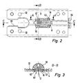
- FIG. 1 shows a generally designated by the reference numeral 2 jigsaw according to the invention with a guide plate 4, a substantially vertically above the guide plate 4 above, reciprocally driven jigsaw blade 6 and with a mecanicsfinne 8, which is downstream of the jigsaw blade 6 in the direction of the jigsaw and engages in the saw blade.
- the guide fin 8 is in the FIGS. 7a to c shown in different views. It comprises a plate-shaped holding part 10 and a fin-shaped guide portion 12, which are arranged with their planes perpendicular to each other and preferably non-detachably connected to each other.
- the guide fin 8 can be arranged in two different orientations on the guide plate 4, namely in a first orientation, which means the working position of the guide fin 8 and shown in the figures, and in a second orientation diametrically opposite to the orientation shown in the figures and dashed in FIG. 1 is indicated.
- the guide fin is from the working position shown in the figures in the direction of the double arrow 14 from a Recess 16 in the guide plate 4 can be removed. It can then be rotated by 180 ° and then be used again with the fin-shaped guide section 12 again in the recess 16.
- the fin-shaped guide section 12 of the guide fin 8 then extends through the guide plate 4 upwards in the direction of a machine housing of the jigsaw 2.
- the plate-shaped holding part 10 which may for example be formed of plastic, in this case comprises a stabilizing verripte structure which gives the holding part 10 a torsional stability.
- the plate-shaped holding part On two opposite narrow sides 22, the plate-shaped holding part in each case in the direction of the narrow sides 22 extending rib 24 and a projection 26, which form-fit underreaching sections 28 to hold the guide fin 8 in the recess 16 positively.
- the holding part 10 is perpendicular to the fin-shaped guide portion 12 from which is preferably formed of metal.
- the guide plate 4 is substantially planar extending and includes a direction extending in the direction of recess 30 for the jigsaw blade 6 and the already mentioned recess 16, in which the guide fin 8, as in the FIGS. 2 to 6 shown, can be used.
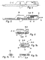
- a housing-forming component 30 (FIG. FIGS. 3 to 5 ) is provided, which forms a tubular or tunnel-shaped receptacle for the relative to the guide plate 4 manually adjustable means 18.
- This housing-forming component 30 is preferably formed from a metal plate, which in the FIG. 3 apparent shape has been brought and cohesively connected to the guide plate 4 via rivet-like connection means 32.
- the manually adjustable means 18 is longitudinally displaceable, so in the direction of the double arrow 34 slidably provided.
- the means 18 is formed by a piece in the form of a part in the form of a slide 36 with the already mentioned manual pusher surface 20.
- the pusher surface 20 could also be formed by a separate part.
- the slider 36 is biased by a spring 38 in a direction of adjustment (direction of the double arrow 34), wherein the spring 38 is supported between a step 40 of the slider 36 and a folded portion 42 of the housing-forming component 30.
- the slider 36 Upon application of manual pressure on the pusher surface 20, the slider 36 is counter to the spring force in the FIG. 5 moved to the left.
- the manually adjustable means 18, ie the slider 36 has an opening 40, which is best FIG. 3 it can be seen in which opening the guide fin can be inserted, when the slide is pushed by pressure on the pusher surface 20 in FIG FIG. 5 was moved to the left.
- the slider 36 further comprises projecting into this opening 40 engaging cross-sections 42, which with the engageable portions 28 of the holding part 10 of the guide fin 8 ( Figures 3 and 6 ).
- the guide fin 8 with its plate-shaped holding part 10 can be inserted through the recess 16 of the guide plate 4 and into the opening 40 of the slider 36.
- the under-engaging portions 42 of the slider 36 do not collide in this position of the slider 36 with the engageable portions 28 of the plate-shaped holding part 10 of the guide fin 8. Only upon reducing the manual pressure on the pusher surface 20 of the slider 36 is under the action of the spring 38 in the FIG. 5 moved to the right, so that the under-engaging portions 42 of the slider 36 engage under the engageable portions 28 of the holding part 10 of the guide fin 8 form fit.
- the guide fin 8 or its plate-shaped holding part 10 is received immovably in the recess 16 of the guide plate 4. It can thus get into the form-fitting arrangement shown in the figures in the recess 16 of the guide plate 4.
- the slider 36 is actuated again, the applicantssfinne is removed, rotated by 180 ° and inserted with its fin-shaped guide portion 12 ahead again in the recess 16 of the guide plate 4 and in the slide 36. In this case, then shows the fin-shaped guide portion 12 upwards, and the plate-shaped holding part 10 is preferably flush with the workpiece-facing side of the guide plate 4th
Landscapes
- Engineering & Computer Science (AREA)
- Mechanical Engineering (AREA)
- Sawing (AREA)
Abstract
Description
Die Erfindung betrifft eine motorisch angetriebene handgeführte Stichsäge mit einem Maschinengehäuse und mit einer werkstückzugewandten Führungsplatte, über die das Stichsägenblatt hin- und hergehend antreibbar vorsteht, wobei an der werkstückzugewandten Seite der Führungsplatte eine Führungsfinne lösbar anbringbar ist, welche dem Stichsägenblatt in Arbeitsrichtung nachgeordnet ist und in den Sägespalt eingreift, wobei die Führungsfinne in einer Vertiefung oder Ausnehmung in der Führungsplatte gehalten ist.The invention relates to a motor-driven hand-held jigsaw with a machine housing and a workpiece-facing guide plate over which the jigsaw blade reciprocally protrudes driven, wherein on the workpiece facing side of the guide plate a Führungsfinne is releasably attachable, which is arranged downstream of the jigsaw blade in the working direction and in engages the saw blade, wherein the guide fin is held in a recess or recess in the guide plate.
Eine solche Stichsäge ist beispielsweise bekannt aus
Der vorliegenden Erfindung liegt die Aufgabe zugrunde, eine Stichsäge der eingangs genannten Art weiter dahingehend zu verbessern, dass die Führungsfinne einerseits komfortabel in ihrer bestimmungsgemäßen Arbeitsposition angeordnet werden kann, ohne eine Vielzahl von Handgriffen oder gar Werkzeuge zu erfordern. Weiter soll die Führungsfinne ebenso komfortabel lösbar sein, und es soll möglichst verhindert werden, dass die Führungsfinne verloren geht, wenn sie nicht benötigt wird.The present invention has for its object to further improve a jigsaw of the type mentioned in that the guide fin on the one hand can be conveniently placed in its intended working position, without requiring a variety of handles or even tools. Next, the Führungsfinne should be just as easily solvable, and it should be prevented if possible, that the Führungsfinne is lost when it is not needed.
Diese Aufgabe wird bei einer Stichsäge der gattungsgemäßen Art erfindungsgemäß dadurch gelöst, dass die Führungsfinne und die Vertiefung oder Ausnehmung in der Führungsplatte so ausgebildet sind, dass die Führungsfinne in zwei verschiedenen Orientierungen zur Ebene der Führungsplatte jeweils formschlüssig in der Vertiefung oder Ausnehmung in der Führungsplatte anordenbar ist, wobei sie in der einen Orientierung mit ihrem finnenförmigen Führungsabschnitt über die Führungsplatte vorsteht und bestimmungsgemäß verwendbar ist und in der anderen Orientierung nicht über die Führungsplatte vorsteht und sich in einer unverlierbaren Verstaustellung befindet.
Die Führungsfinne ist also aus der Vertiefung oder Ausnehmung in der Führungsplatte entnehmbar, wenn die Stichsäge ohne Verwendung dieses "Führungshilfsmittels" eingesetzt werden soll. Die Führungsfinne kann dann beispielsweise beiseite gelegt oder in der Hosentasche des Benutzers mitgeführt werden, was jedoch die Gefahr des Verlorengehens erhöht. Daher wird erfindungsgemäß vorgeschlagen, dass die Führungsfinne, nachdem sie entnommen wurde, in eine andere Orientierung zur Ebene der Führungsplatte gedreht wird und wieder in die Vertiefung oder Ausnehmung angeordnet und dort formschlüssig gehalten wird. In dieser im Vergleich zu ihrer Arbeitsstellung verschwenkten oder verdrehten Orientierung steht die Führungsfinne nicht über die Führungsplatte vor. Die Stichsäge kann dann in herkömmlicher Weise verwendet werden. Zugleich ist aber sichergestellt, dass die Führungsfinne unverlierbar mit der Stichsäge mitgeführt wird. Die Gefahr, dass die Führungsfinne verloren geht, besteht daher nicht mehr. Hierdurch ist die Handhabbarkeit der Stichsäge und ihrer Komponenten wesentlich verbessert.This object is achieved in a jigsaw of the generic type according to the invention that the Führungsfinne and the recess or recess in the guide plate are formed so that the Führungsfinne in two different orientations to the plane of the guide plate each form fit in the recess or recess in the guide plate can be arranged is, wherein it protrudes in one orientation with its fin-shaped guide portion on the guide plate and is used as intended and in the other orientation does not project beyond the guide plate and is in a captive stowed position.
The Führungsfinne is thus removed from the recess or recess in the guide plate when the jigsaw without use of this "guide tool" is to be used. The guide fin can then be set aside, for example, or carried in the user's trouser pocket, but this increases the risk of getting lost. Therefore, it is proposed according to the invention that the guide fin, after they has been removed, is rotated in a different orientation to the plane of the guide plate and again arranged in the recess or recess and held there form-fitting. In this orientation, which is pivoted or twisted compared to its working position, the guide fin does not protrude beyond the guide plate. The jigsaw can then be used in a conventional manner. At the same time, however, it is ensured that the guide fin is carried along captive with the jigsaw. The danger that the leaders will be lost, therefore, is no longer. As a result, the handling of the jigsaw and its components is significantly improved.
Beispielsweise wäre es denkbar, dass die Führungsfinne aus ihrer bestimmungsgemäßen Arbeitsposition entnommen und dann um 90° gedreht wird, so dass die Ebene des finnenförmigen Führungsabschnitts im Wesentlichen parallel zur Ebene der Führungsplatte ist, und dass die Führungsfinne dann in dieser Orientierung in die Vertiefung oder Ausnehmung in der Führungsplatte einsetzbar ist. Nach dieser Ausführungsform kann die Vertiefung oder Ausnehmung in der Führungsplatte auch verhältnismäßig flach ausgebildet sein. Bevorzugt wird jedoch eine Ausführungsform, bei der die beiden genannten Orientierungen - der aktiven Arbeitsstellung und der inaktiven Verstaustellung - einander entgegengesetzt sind. Die Führungsfinne wird solchenfalls entnommen und um 180° gedreht und wieder in die Ausnehmung oder Vertiefung eingesetzt, in der sie dann formschlüssig gehalten wird. Die Führungsfinne zeigt dann vom Werkstück weg in Richtung auf das Maschinengehäuse der Stichsäge.For example, it would be conceivable that the guide fin is removed from its intended working position and then rotated by 90 °, so that the plane of the fin-shaped guide portion is substantially parallel to the plane of the guide plate, and that the guide fin then in this orientation in the recess or recess can be used in the guide plate. According to this embodiment, the recess or recess in the guide plate may also be formed relatively flat. However, preferred is an embodiment in which the two mentioned orientations - the active working position and the inactive stowed position - are opposite to each other. The guide fin is removed in this case and rotated by 180 ° and used again in the recess or depression, in which it is then held positively. The guide fin then points away from the workpiece towards the machine housing of the jigsaw.
Nach einem weiteren Erfindungsgedanken, für den ebenfalls unabhängig von der Anordnung der Führungsfinne in den beiden Orientierungen Schutz in Anspruch genommen wird, ist die Führungsfinne durch ein gegenüber der Führungsplatte manuell verstellbares Mittel formschlüssig und unverlierbar an der Führungsplatte gehalten. Vorzugsweise umfasst das gegenüber der Führungsplatte verstellbare Mittel einen Schieber. Auf diese Weise wird also durch einfache Verstellung des Mittels, vorzugsweise durch eine lineare Stell- oder Verschiebebewegung, die formschlüssige Halterung der Führungsfinne einerseits und die Freigabe der Führungsfinne andererseits erreicht.According to a further concept of the invention, for which protection is likewise claimed independently of the arrangement of the guide fingers in the two orientations, is the Führungsfinne held by a relative to the guide plate manually adjustable means form-fitting and captive on the guide plate. Preferably, the means adjustable relative to the guide plate comprises a slider. In this way, therefore, the positive retention of the guide fin on the one hand and the release of the guide fin on the other hand achieved by simple adjustment of the means, preferably by a linear adjusting or sliding movement.
Nach einem weiteren Erfindungsgedanken erweist es sich als vorteilhaft, wenn das gegenüber Führungsplatte verstellbare Mittel in Arbeitsrichtung der Stichsäge, also in Richtung des Sägeschnitts oder entgegengesetzt, stellbar ist.According to a further inventive concept, it proves to be advantageous if the means adjustable relative to the guide plate in the working direction of the jigsaw, ie in the direction of the saw cut or opposite, is adjustable.
Weiter erweist es sich als vorteilhaft, wenn das gegenüber der Führungsplatte verstellbare Mittel in eine Richtung vorgespannt ist, wobei hier insbesondere eine Feder, aber auch ein sonstiges elastisches Mittel in Frage kommt. Die Betätigung des manuell verstellbaren Mittels erfolgt dann entgegen der Vorspannung, wobei das Mittel solchenfalls aufgrund seiner Vorspannung stets selbsttätig in eine End-oder Anschlagstellung zurückbewegt wird.Further, it proves to be advantageous if the adjustable relative to the guide plate means is biased in one direction, in which case in particular a spring, but also some other elastic means in question. The operation of the manually adjustable means is then carried out against the bias, the agent is such case always automatically moved back into an end or stop position due to its bias.
Als besonders vorteilhaft erweist es sich, wenn bei Betätigung des gegenüber der Führungsplatte verstellbaren Mittels die Führungsfinne schwerkraftbedingt aus der Vertiefung oder Ausnehmung bei der Führungsplatte herausfallbar ausgebildet ist, und zwar ohne dass weitere Hilfsmittel angewandt werden müssten oder der Benutzer mit den Fingern der anderen Hand nachgreifen müsste. Die andere Hand kann vielmehr zum Auffangen der aus der Vertiefung oder Ausnehmung fallenden Führungsfinne verwendet werden.It proves to be particularly advantageous if, on actuation of the guide plate, which can be adjusted relative to the guide fin, due to gravity, can be made to fall out of the depression or recess in the guide plate, without the need for further aids or for the user to pick up the fingers of the other hand would. Rather, the other hand can be used to catch the guide fingers falling out of the recess or recess.
Weiter wird vorgeschlagen, dass das gegenüber Führungsplatte verstellbare Mittel auf der werkstückabgewandten Seite der Führungsplatte vorgesehen ist. Dies gestaltet die Führung und Unterbringung des Mittels einfacher, und die Stabilität der Führungsplatte als Ganzes wird weniger beeinträchtigt. Hierfür erweist es sich als vorteilhaft, wenn auf der werkstückabgewandten Seite der Führungsplatte eine für das verstellbare Mittel gehäusebildende, vorzugsweise metallische Komponente ausgebildet ist. Diese gehäusebildende Komponente könnte beispielsweise insbesondere zusammen mit der Führungsplatte eine tunnel- oder röhrenförmige Aufnahme für das verstellbare Mittel bilden.It is further proposed that the means adjustable with respect to the guide plate is provided on the workpiece side facing away from the guide plate. This makes the guidance and placement of the agent easier, and the stability of the guide plate as a whole is less affected. For this purpose, it proves to be advantageous if formed on the workpiece side facing away from the guide plate for the adjustable means housing forming, preferably metallic component. This housing-forming component could, for example, together with the guide plate form a tunnel or tubular receptacle for the adjustable means.
Die genannte gehäusebildende Komponente kann auf der werkstückabgewandten Seite der Führungsplatte eine Bauhöhe von 10 bis 30 mm, insbesondere von 10 bis 25 mm und weiter insbesondere von 10 bis 20 mm aufweisen. Dieser Bereich oberhalb der Führungsplatte und in Bearbeitungsrichtung dem Stichsägeblatt nachgeordnet steht typischerweise für die vorstehend genannten Bauhöhen zur Verfügung, so dass diese ohne weiteres vorgesehen werden können. Somit steht ausreichend Bauraum für eine kostengünstige und stabile sowie zweckmäßige und handhabbare Ausbildung des verstellbaren Mittels zur Verfügung.Said housing-forming component may have a height of 10 to 30 mm, in particular from 10 to 25 mm and more particularly from 10 to 20 mm on the workpiece side facing away from the guide plate. This area above the guide plate and downstream of the jigsaw blade in the machine direction is typically available for the aforementioned heights, so that they can be readily provided. Thus, there is sufficient space for a cost-effective and stable and convenient and manageable training of the adjustable means available.
Vorteilhafterweise ist das gegenüber der Führungsplatte verstellbare Mittel als Kunststoffspritzteil ausgebildet, was eine komplexe Ausbildung bei moderaten Herstellkosten zulässt.Advantageously, the adjustable relative to the guide plate means is formed as a plastic injection molded part, which allows a complex training at moderate production costs.
Das gegenüber der Führungsplatte verstellbare Mittel könnte in an sich beliebiger unmittelbarer oder mittelbarer Weise manuell betätigt werden. Es erweist sich indessen als vorteilhaft, wenn das Mittel eine Drückerfläche aufweist und durch manuellen Druck auf diese Drückerfläche in Stellrichtung des Mittels direkt betätigbar ist. Auf diese Weise müssen keine die Stellkraft umlenkenden Mittel vorgesehen werden, sondern der Benutzer drückt gewissermaßen direkt in Stellrichtung auf das Mittel und führt somit die Stellbewegung aus.The adjustable relative to the guide plate means could be manually operated in any desired directly or indirectly. However, it proves to be advantageous if the means has a pusher surface and by manual pressure on this pusher surface in the direction of the means is directly operable. In this way, no adjusting means deflecting means must be provided, but the user presses in a sense directly in the direction of adjustment to the means and thus performs the adjusting movement.
Es erweist sich weiter als zweckmäßig und vorteilhaft, wenn die Führungsfinne ein plattenförmiges Halteteil umfasst, welches solchenfalls vorzugsweise mit seiner Plattenebene senkrecht zur Ebene des finnenförmigen Führungsabschnitts der Führungsfinne erstreckt ist. Das plattenförmige Halteteil kann dann die formschlüssige Anordnung der Führungsfinne in der Vertiefung oder Ausnehmung bewirken, indem es in geeigneter Weise mit dem manuell verstellbaren Mittel formschlüssig zusammenwirkt. Hierfür erweist es sich als vorteilhaft, wenn die Führungsfinne oder ein plattenförmiges Halteteil der Führungsfinne formschlüssig untergreifbare Abschnitte aufweist, die insbesondere seitlich vorstehend ausgebildet sind.It also proves to be expedient and advantageous if the guide fin comprises a plate-shaped holding part which, in this case, preferably extends with its plate plane perpendicular to the plane of the fin-shaped guide section of the guide fin. The plate-shaped holding part can then bring about the form-fitting arrangement of the guide fin in the recess or recess, by interacting in a form-fitting manner with the manually adjustable means in a suitable manner. For this it proves to be advantageous if the Führungsfinne or a plate-shaped holding part of the guide fin has positively engrossed undercut portions which are formed in particular laterally projecting.
Weiter erweist es sich als vorteilhaft, wenn das gegenüber der Führungsplatte verstellbare Mittel eine Öffnung aufweist, in welche die Führungsfinne einlegbar ist und durch welche die Führungsfinne in der Verstaustellung mit ihrem finnenförmigen Führungsabschnitt hindurchgreift. In diesem Fall kann das verstellbare Mittel und die Führungsfinne bzw. die Vertiefung oder Ausnehmung in der Führungsplatte derart miteinander zusammenwirken, dass die Führungsfinne in die Vertiefung oder Ausnehmung einsetzbar ist, wenn das verstellbare Mittel, insbesondere entgegen der Federkraft, betätigt wird. Wenn das Mittel manuell oder federkraftbedingt in Richtung auf seine unbetätigte Stellung zurückbewegt wird, so gleitet es gegenüber der Führungsfinne, die im Wesentlichen unverschieblich in der Vertiefung oder Ausnehmung der Führungsplatte gehalten ist. Dabei gerät das stellbare Mittel in eine Hintergriffsstellung mit der Führungsfinne, was die formschlüssige Anordnung der Führungsfinne in der Vertiefung oder Ausnehmung bewirkt.Furthermore, it proves to be advantageous if the means adjustable relative to the guide plate has an opening into which the guide finger can be inserted and through which the guide finger engages in the stowed position with its fin-shaped guide section. In this case, the adjustable means and the guide fin or the recess or recess in the guide plate cooperate with each other such that the guide fin is insertable into the recess or recess when the adjustable means, in particular against the spring force is actuated. When the means is manually or spring moved back towards its unactuated position, it slides against the guide fin, which is substantially immovable in the Recess or recess of the guide plate is held. In this case, the adjustable means gets into a rear grip position with the guide fin, which causes the positive arrangement of the guide fin in the recess or recess.
Ferner erweist es sich als vorteilhaft, wenn die Führungsfinne in die Vertiefung oder Ausnehmung senkrecht zur Ebene der Führungsplatte einsetzbar ist und darin vorzugsweise unverschieblich angeordnet ist. Es wäre jedoch auch eine Ausführungsform denkbar, bei der die Führungsfinne durch das Mittel in eine Hintergriffsstellung verschiebbar ist.Furthermore, it proves to be advantageous if the Führungsfinne is inserted into the recess or recess perpendicular to the plane of the guide plate and is preferably arranged immovably therein. However, it would also be conceivable an embodiment in which the guide fin is displaceable by the means in a rear grip position.
Weiter wird vorgeschlagen, dass die Führungsfinne oder ein plattenförmiges Halteteil der Führungsfinne in ihrer unverlierbaren Verstaustellung im wesentlichen flächenbündig zur werkstückzugewandten Oberseite der Führungsplatte angeordnet ist.It is further proposed that the guide fin or a plate-shaped holding part of the guide fin is arranged in its captive stowed position substantially flush with the workpiece facing top of the guide plate.
Weitere Merkmale, Vorteile und Einzelheiten der Erfindung ergeben sich aus den beigefügten Patentansprüchen und der zeichnerischen Darstellung und nachfolgenden Beschreibung einer bevorzugten Ausführungsform der erfindungsgemäßen Stichsäge. In der Zeichnung zeigt:
- Figur 1
- eine Seitenansicht einer erfindungsgemäßen Stichsäge mit einer Führungsfinne;
- Figur 2
- eine Ansicht der Führungsplatte der erfindungsgemäßen Stichsäge von unten;
- Figur 3
- eine Schnittansicht mit Schnittebene B-B in
Figur 2 ; - Figur 4
- eine Seitenansicht der Führungsplatte nach
Figur 2 ; - Figur 5
- eine Längsschnittansicht mit Schnittebene C-C in
Figur 2 ; - Figur 6
- eine Schnittansicht mit Schnittebene A-A in
Figur 2 ; - Figuren 7a - c
- Ansichten der Führungsfinne von unten, von der Seite und von vorn.
- FIG. 1
- a side view of a jigsaw invention with a guide fin;
- FIG. 2
- a view of the guide plate of the jigsaw according to the invention from below;
- FIG. 3
- a sectional view with sectional plane BB in
FIG. 2 ; - FIG. 4
- a side view of the guide plate after
FIG. 2 ; - FIG. 5
- a longitudinal sectional view with sectional plane CC in
FIG. 2 ; - FIG. 6
- a sectional view with sectional plane AA in
FIG. 2 ; - FIGS. 7a-c
- Views of the guide fin from below, from the side and from the front.
Erfindungsgemäß ist die Führungsfinne 8 in zwei unterschiedlichen Orientierungen an der Führungsplatte 4 anordenbar, nämlich in einer ersten Orientierung, welche die Arbeitsstellung der Führungsfinne 8 bedeutet und in den Figuren dargestellt ist, und in einer zweiten Orientierung, die der in den Figuren dargestellten Orientierung diametral entgegengesetzt und gestrichelt in
Zunächst wird anhand der
Die Führungsplatte 4 ist im Wesentlichen flächenhaft erstreckt und umfasst eine in Arbeitsrichtung erstreckte Ausnehmung 30 für das Stichsägenblatt 6 und die schon erwähnte Ausnehmung 16, in welche die Führungsfinne 8, wie in den
Auf der vom Werkstück abgewandten Seite der Führungsplatte 4 ist eine gehäusebildende Komponente 30 (
Das manuell verstellbare Mittel 18, d. h. der Schieber 36, weist eine Öffnung 40 auf, die am besten aus
Zum Lösen der Führungsfinne 8 wird erneut der Schieber 36 betätigt, die Führungsfinne wird entnommen, um 180° gedreht und mit ihrem finnenförmigen Führungsabschnitt 12 voraus wieder in die Ausnehmung 16 der Führungsplatte 4 und in den Schieber 36 eingesteckt. Dabei zeigt dann der finnenförmige Führungsabschnitt 12 nach oben, und das plattenförmige Halteteil 10 verläuft vorzugsweise flächenbündig zu der werkstückzugewandten Seite der Führungsplatte 4.To release the
Claims (15)
Applications Claiming Priority (1)
| Application Number | Priority Date | Filing Date | Title |
|---|---|---|---|
| DE200810016765 DE102008016765B3 (en) | 2008-04-02 | 2008-04-02 | Jig saw with guide fin |
Publications (3)
| Publication Number | Publication Date |
|---|---|
| EP2106871A2 true EP2106871A2 (en) | 2009-10-07 |
| EP2106871A3 EP2106871A3 (en) | 2013-08-28 |
| EP2106871B1 EP2106871B1 (en) | 2014-12-31 |
Family
ID=40758678
Family Applications (1)
| Application Number | Title | Priority Date | Filing Date |
|---|---|---|---|
| EP20090004633 Not-in-force EP2106871B1 (en) | 2008-04-02 | 2009-03-31 | Fret saw with guide fin |
Country Status (2)
| Country | Link |
|---|---|
| EP (1) | EP2106871B1 (en) |
| DE (1) | DE102008016765B3 (en) |
Cited By (2)
| Publication number | Priority date | Publication date | Assignee | Title |
|---|---|---|---|---|
| US8578615B2 (en) | 2011-09-12 | 2013-11-12 | Black & Decker Inc. | Jigsaw with deployable keel and tiltable shoe |
| US9899899B2 (en) | 2013-10-25 | 2018-02-20 | Black & Decker Inc. | Handheld power tool with compact AC switch |
Citations (2)
| Publication number | Priority date | Publication date | Assignee | Title |
|---|---|---|---|---|
| DE3021801C2 (en) | 1980-06-11 | 1985-03-21 | Licentia Patent-Verwaltungs-Gmbh, 6000 Frankfurt | Jigsaw with support table that can be attached to the saw housing |
| DE10300793A1 (en) | 2003-01-13 | 2004-07-22 | Robert Bosch Gmbh | Electric hand tool has guide element mounted on underneath of base plate flush with cutting tool to fit into guide groove forming cutting line on workpiece |
Family Cites Families (3)
| Publication number | Priority date | Publication date | Assignee | Title |
|---|---|---|---|---|
| US4272889A (en) * | 1979-02-26 | 1981-06-16 | Omark Industries, Inc. | Portable saw |
| DE4104296A1 (en) * | 1991-02-13 | 1992-08-20 | Licentia Gmbh | Hand-guided jigsaw with bottom guide plate - has downward protruding blade acting as riving knife and guideway for adjustable guide plate |
| DE10300796A1 (en) * | 2003-01-13 | 2004-07-22 | Robert Bosch Gmbh | Rotor design especially for commutator motor, has reactive volume-enlarging working material expanding in armature winding coil |
-
2008
- 2008-04-02 DE DE200810016765 patent/DE102008016765B3/en not_active Expired - Fee Related
-
2009
- 2009-03-31 EP EP20090004633 patent/EP2106871B1/en not_active Not-in-force
Patent Citations (2)
| Publication number | Priority date | Publication date | Assignee | Title |
|---|---|---|---|---|
| DE3021801C2 (en) | 1980-06-11 | 1985-03-21 | Licentia Patent-Verwaltungs-Gmbh, 6000 Frankfurt | Jigsaw with support table that can be attached to the saw housing |
| DE10300793A1 (en) | 2003-01-13 | 2004-07-22 | Robert Bosch Gmbh | Electric hand tool has guide element mounted on underneath of base plate flush with cutting tool to fit into guide groove forming cutting line on workpiece |
Cited By (2)
| Publication number | Priority date | Publication date | Assignee | Title |
|---|---|---|---|---|
| US8578615B2 (en) | 2011-09-12 | 2013-11-12 | Black & Decker Inc. | Jigsaw with deployable keel and tiltable shoe |
| US9899899B2 (en) | 2013-10-25 | 2018-02-20 | Black & Decker Inc. | Handheld power tool with compact AC switch |
Also Published As
| Publication number | Publication date |
|---|---|
| EP2106871B1 (en) | 2014-12-31 |
| EP2106871A3 (en) | 2013-08-28 |
| DE102008016765B3 (en) | 2009-07-16 |
Similar Documents
| Publication | Publication Date | Title |
|---|---|---|
| EP1790441B1 (en) | Knife | |
| EP0682589B1 (en) | Interchangeable handle for slide blocks | |
| EP2412490B1 (en) | Fastening system | |
| DE202011052256U1 (en) | Medical instrument | |
| EP2106871B1 (en) | Fret saw with guide fin | |
| EP2018922A2 (en) | Circular saw stand | |
| EP2787903B1 (en) | Medical instrument | |
| WO2013171147A1 (en) | Device for fixing a workpiece which is to be machined by means of a corresponding machine | |
| EP2974824A2 (en) | Guide system comprising a handheld machine tool and guide rail | |
| EP1466690A1 (en) | Saber saw with adjusting device for a guide | |
| EP1944135A1 (en) | Clamp tool with a stand | |
| EP0855239A1 (en) | Quick-clamping device in a machining apparatus | |
| EP1333962A1 (en) | Cutting device comprising two jaws which can be moved one over the other by means of manual operation | |
| WO2005108026A1 (en) | Cutting device | |
| EP1854602B1 (en) | Device for the cutting to size of edge strips | |
| EP2656990B1 (en) | Slate cutters | |
| DE102006006592A1 (en) | Mechanism for locking a scraper tool | |
| DE102019110984A1 (en) | CLAMPING HOLDER | |
| DE102015103028B4 (en) | tile cutter | |
| DE102009007372B4 (en) | Saw blade | |
| EP0611634A1 (en) | Multi purpose knife | |
| DE102010020655A1 (en) | Water pumping pliers comprise two pliers units that cross in connecting area, where pliers units are swiveled by joint, and spring element is arranged at resting block | |
| DE202006003049U1 (en) | Hand saw, comprising blade to be adjusted in length and fixed with locking screw | |
| DE202020100540U1 (en) | Cutter knife | |
| WO2018215115A1 (en) | Combined shaving and trimming device |
Legal Events
| Date | Code | Title | Description |
|---|---|---|---|
| PUAI | Public reference made under article 153(3) epc to a published international application that has entered the european phase |
Free format text: ORIGINAL CODE: 0009012 |
|
| AK | Designated contracting states |
Kind code of ref document: A2 Designated state(s): AT BE BG CH CY CZ DE DK EE ES FI FR GB GR HR HU IE IS IT LI LT LU LV MC MK MT NL NO PL PT RO SE SI SK TR |
|
| AX | Request for extension of the european patent |
Extension state: AL BA RS |
|
| PUAL | Search report despatched |
Free format text: ORIGINAL CODE: 0009013 |
|
| AK | Designated contracting states |
Kind code of ref document: A3 Designated state(s): AT BE BG CH CY CZ DE DK EE ES FI FR GB GR HR HU IE IS IT LI LT LU LV MC MK MT NL NO PL PT RO SE SI SK TR |
|
| AX | Request for extension of the european patent |
Extension state: AL BA RS |
|
| RIC1 | Information provided on ipc code assigned before grant |
Ipc: B23D 51/02 20060101ALI20130719BHEP Ipc: B23D 49/16 20060101AFI20130719BHEP |
|
| 17P | Request for examination filed |
Effective date: 20140225 |
|
| RBV | Designated contracting states (corrected) |
Designated state(s): AT BE BG CH CY CZ DE DK EE ES FI FR GB GR HR HU IE IS IT LI LT LU LV MC MK MT NL NO PL PT RO SE SI SK TR |
|
| RBV | Designated contracting states (corrected) |
Designated state(s): AT BE BG CH CY CZ DE DK EE ES FI FR GB GR HR HU IE IS IT LI LT LU LV MC MK MT NL NO PL PT RO SE SI SK TR |
|
| AKX | Designation fees paid |
Designated state(s): AT BE BG CH CY CZ LI |
|
| REG | Reference to a national code |
Ref country code: DE Ref legal event code: R108 |
|
| REG | Reference to a national code |
Ref legal event code: R108 Ref document number: 502009010413 Country of ref document: DE Ref country code: DE Effective date: 20140507 |
|
| GRAP | Despatch of communication of intention to grant a patent |
Free format text: ORIGINAL CODE: EPIDOSNIGR1 |
|
| INTG | Intention to grant announced |
Effective date: 20140616 |
|
| GRAS | Grant fee paid |
Free format text: ORIGINAL CODE: EPIDOSNIGR3 |
|
| RBV | Designated contracting states (corrected) |
Designated state(s): AT BE BG CH CY CZ DE DK EE ES FI FR GB GR HR HU IE IS IT LI LT LU LV MC MK MT NL NO PL PT RO SE SI SK TR |
|
| GRAA | (expected) grant |
Free format text: ORIGINAL CODE: 0009210 |
|
| AK | Designated contracting states |
Kind code of ref document: B1 Designated state(s): AT BE BG CH CY CZ DE DK EE ES FI FR GB GR HR HU IE IS IT LI LT LU LV MC MK MT NL NO PL PT RO SE SI SK TR |
|
| REG | Reference to a national code |
Ref country code: CH Ref legal event code: EP Ref country code: GB Ref legal event code: FG4D Free format text: NOT ENGLISH |
|
| REG | Reference to a national code |
Ref country code: IE Ref legal event code: FG4D Free format text: LANGUAGE OF EP DOCUMENT: GERMAN |
|
| REG | Reference to a national code |
Ref country code: AT Ref legal event code: REF Ref document number: 704081 Country of ref document: AT Kind code of ref document: T Effective date: 20150215 |
|
| REG | Reference to a national code |
Ref country code: DE Ref legal event code: R096 Ref document number: 502009010413 Country of ref document: DE Effective date: 20150219 |
|
| PG25 | Lapsed in a contracting state [announced via postgrant information from national office to epo] |
Ref country code: LT Free format text: LAPSE BECAUSE OF FAILURE TO SUBMIT A TRANSLATION OF THE DESCRIPTION OR TO PAY THE FEE WITHIN THE PRESCRIBED TIME-LIMIT Effective date: 20141231 Ref country code: FI Free format text: LAPSE BECAUSE OF FAILURE TO SUBMIT A TRANSLATION OF THE DESCRIPTION OR TO PAY THE FEE WITHIN THE PRESCRIBED TIME-LIMIT Effective date: 20141231 Ref country code: NO Free format text: LAPSE BECAUSE OF FAILURE TO SUBMIT A TRANSLATION OF THE DESCRIPTION OR TO PAY THE FEE WITHIN THE PRESCRIBED TIME-LIMIT Effective date: 20150331 |
|
| REG | Reference to a national code |
Ref country code: NL Ref legal event code: VDEP Effective date: 20141231 |
|
| REG | Reference to a national code |
Ref country code: LT Ref legal event code: MG4D |
|
| PG25 | Lapsed in a contracting state [announced via postgrant information from national office to epo] |
Ref country code: GR Free format text: LAPSE BECAUSE OF FAILURE TO SUBMIT A TRANSLATION OF THE DESCRIPTION OR TO PAY THE FEE WITHIN THE PRESCRIBED TIME-LIMIT Effective date: 20150401 Ref country code: SE Free format text: LAPSE BECAUSE OF FAILURE TO SUBMIT A TRANSLATION OF THE DESCRIPTION OR TO PAY THE FEE WITHIN THE PRESCRIBED TIME-LIMIT Effective date: 20141231 Ref country code: HR Free format text: LAPSE BECAUSE OF FAILURE TO SUBMIT A TRANSLATION OF THE DESCRIPTION OR TO PAY THE FEE WITHIN THE PRESCRIBED TIME-LIMIT Effective date: 20141231 Ref country code: LV Free format text: LAPSE BECAUSE OF FAILURE TO SUBMIT A TRANSLATION OF THE DESCRIPTION OR TO PAY THE FEE WITHIN THE PRESCRIBED TIME-LIMIT Effective date: 20141231 |
|
| PG25 | Lapsed in a contracting state [announced via postgrant information from national office to epo] |
Ref country code: NL Free format text: LAPSE BECAUSE OF FAILURE TO SUBMIT A TRANSLATION OF THE DESCRIPTION OR TO PAY THE FEE WITHIN THE PRESCRIBED TIME-LIMIT Effective date: 20141231 |
|
| PG25 | Lapsed in a contracting state [announced via postgrant information from national office to epo] |
Ref country code: RO Free format text: LAPSE BECAUSE OF FAILURE TO SUBMIT A TRANSLATION OF THE DESCRIPTION OR TO PAY THE FEE WITHIN THE PRESCRIBED TIME-LIMIT Effective date: 20141231 Ref country code: CZ Free format text: LAPSE BECAUSE OF FAILURE TO SUBMIT A TRANSLATION OF THE DESCRIPTION OR TO PAY THE FEE WITHIN THE PRESCRIBED TIME-LIMIT Effective date: 20141231 Ref country code: SK Free format text: LAPSE BECAUSE OF FAILURE TO SUBMIT A TRANSLATION OF THE DESCRIPTION OR TO PAY THE FEE WITHIN THE PRESCRIBED TIME-LIMIT Effective date: 20141231 Ref country code: ES Free format text: LAPSE BECAUSE OF FAILURE TO SUBMIT A TRANSLATION OF THE DESCRIPTION OR TO PAY THE FEE WITHIN THE PRESCRIBED TIME-LIMIT Effective date: 20141231 |
|
| PG25 | Lapsed in a contracting state [announced via postgrant information from national office to epo] |
Ref country code: PL Free format text: LAPSE BECAUSE OF FAILURE TO SUBMIT A TRANSLATION OF THE DESCRIPTION OR TO PAY THE FEE WITHIN THE PRESCRIBED TIME-LIMIT Effective date: 20141231 Ref country code: IS Free format text: LAPSE BECAUSE OF FAILURE TO SUBMIT A TRANSLATION OF THE DESCRIPTION OR TO PAY THE FEE WITHIN THE PRESCRIBED TIME-LIMIT Effective date: 20150430 |
|
| REG | Reference to a national code |
Ref country code: DE Ref legal event code: R097 Ref document number: 502009010413 Country of ref document: DE |
|
| PG25 | Lapsed in a contracting state [announced via postgrant information from national office to epo] |
Ref country code: EE Free format text: LAPSE BECAUSE OF FAILURE TO SUBMIT A TRANSLATION OF THE DESCRIPTION OR TO PAY THE FEE WITHIN THE PRESCRIBED TIME-LIMIT Effective date: 20141231 Ref country code: MC Free format text: LAPSE BECAUSE OF FAILURE TO SUBMIT A TRANSLATION OF THE DESCRIPTION OR TO PAY THE FEE WITHIN THE PRESCRIBED TIME-LIMIT Effective date: 20141231 Ref country code: DK Free format text: LAPSE BECAUSE OF FAILURE TO SUBMIT A TRANSLATION OF THE DESCRIPTION OR TO PAY THE FEE WITHIN THE PRESCRIBED TIME-LIMIT Effective date: 20141231 Ref country code: LU Free format text: LAPSE BECAUSE OF FAILURE TO SUBMIT A TRANSLATION OF THE DESCRIPTION OR TO PAY THE FEE WITHIN THE PRESCRIBED TIME-LIMIT Effective date: 20150331 |
|
| REG | Reference to a national code |
Ref country code: CH Ref legal event code: PL |
|
| PLBE | No opposition filed within time limit |
Free format text: ORIGINAL CODE: 0009261 |
|
| STAA | Information on the status of an ep patent application or granted ep patent |
Free format text: STATUS: NO OPPOSITION FILED WITHIN TIME LIMIT |
|
| GBPC | Gb: european patent ceased through non-payment of renewal fee |
Effective date: 20150331 |
|
| 26N | No opposition filed |
Effective date: 20151001 |
|
| PG25 | Lapsed in a contracting state [announced via postgrant information from national office to epo] |
Ref country code: IT Free format text: LAPSE BECAUSE OF FAILURE TO SUBMIT A TRANSLATION OF THE DESCRIPTION OR TO PAY THE FEE WITHIN THE PRESCRIBED TIME-LIMIT Effective date: 20141231 |
|
| REG | Reference to a national code |
Ref country code: FR Ref legal event code: ST Effective date: 20151130 |
|
| REG | Reference to a national code |
Ref country code: IE Ref legal event code: MM4A |
|
| PG25 | Lapsed in a contracting state [announced via postgrant information from national office to epo] |
Ref country code: IE Free format text: LAPSE BECAUSE OF NON-PAYMENT OF DUE FEES Effective date: 20150331 Ref country code: LI Free format text: LAPSE BECAUSE OF NON-PAYMENT OF DUE FEES Effective date: 20150331 Ref country code: CH Free format text: LAPSE BECAUSE OF NON-PAYMENT OF DUE FEES Effective date: 20150331 Ref country code: GB Free format text: LAPSE BECAUSE OF NON-PAYMENT OF DUE FEES Effective date: 20150331 |
|
| PG25 | Lapsed in a contracting state [announced via postgrant information from national office to epo] |
Ref country code: SI Free format text: LAPSE BECAUSE OF FAILURE TO SUBMIT A TRANSLATION OF THE DESCRIPTION OR TO PAY THE FEE WITHIN THE PRESCRIBED TIME-LIMIT Effective date: 20141231 Ref country code: FR Free format text: LAPSE BECAUSE OF NON-PAYMENT OF DUE FEES Effective date: 20150331 |
|
| REG | Reference to a national code |
Ref country code: AT Ref legal event code: MM01 Ref document number: 704081 Country of ref document: AT Kind code of ref document: T Effective date: 20150331 |
|
| PG25 | Lapsed in a contracting state [announced via postgrant information from national office to epo] |
Ref country code: AT Free format text: LAPSE BECAUSE OF NON-PAYMENT OF DUE FEES Effective date: 20150331 |
|
| PG25 | Lapsed in a contracting state [announced via postgrant information from national office to epo] |
Ref country code: MT Free format text: LAPSE BECAUSE OF FAILURE TO SUBMIT A TRANSLATION OF THE DESCRIPTION OR TO PAY THE FEE WITHIN THE PRESCRIBED TIME-LIMIT Effective date: 20141231 |
|
| PG25 | Lapsed in a contracting state [announced via postgrant information from national office to epo] |
Ref country code: BG Free format text: LAPSE BECAUSE OF FAILURE TO SUBMIT A TRANSLATION OF THE DESCRIPTION OR TO PAY THE FEE WITHIN THE PRESCRIBED TIME-LIMIT Effective date: 20141231 Ref country code: HU Free format text: LAPSE BECAUSE OF FAILURE TO SUBMIT A TRANSLATION OF THE DESCRIPTION OR TO PAY THE FEE WITHIN THE PRESCRIBED TIME-LIMIT; INVALID AB INITIO Effective date: 20090331 |
|
| PG25 | Lapsed in a contracting state [announced via postgrant information from national office to epo] |
Ref country code: CY Free format text: LAPSE BECAUSE OF FAILURE TO SUBMIT A TRANSLATION OF THE DESCRIPTION OR TO PAY THE FEE WITHIN THE PRESCRIBED TIME-LIMIT Effective date: 20141231 |
|
| PG25 | Lapsed in a contracting state [announced via postgrant information from national office to epo] |
Ref country code: PT Free format text: LAPSE BECAUSE OF FAILURE TO SUBMIT A TRANSLATION OF THE DESCRIPTION OR TO PAY THE FEE WITHIN THE PRESCRIBED TIME-LIMIT Effective date: 20150501 Ref country code: BE Free format text: LAPSE BECAUSE OF NON-PAYMENT OF DUE FEES Effective date: 20150331 |
|
| PG25 | Lapsed in a contracting state [announced via postgrant information from national office to epo] |
Ref country code: TR Free format text: LAPSE BECAUSE OF FAILURE TO SUBMIT A TRANSLATION OF THE DESCRIPTION OR TO PAY THE FEE WITHIN THE PRESCRIBED TIME-LIMIT Effective date: 20141231 |
|
| PG25 | Lapsed in a contracting state [announced via postgrant information from national office to epo] |
Ref country code: MK Free format text: LAPSE BECAUSE OF FAILURE TO SUBMIT A TRANSLATION OF THE DESCRIPTION OR TO PAY THE FEE WITHIN THE PRESCRIBED TIME-LIMIT Effective date: 20141231 |
|
| PGFP | Annual fee paid to national office [announced via postgrant information from national office to epo] |
Ref country code: DE Payment date: 20220419 Year of fee payment: 14 |
|
| REG | Reference to a national code |
Ref country code: DE Ref legal event code: R119 Ref document number: 502009010413 Country of ref document: DE |
|
| PG25 | Lapsed in a contracting state [announced via postgrant information from national office to epo] |
Ref country code: DE Free format text: LAPSE BECAUSE OF NON-PAYMENT OF DUE FEES Effective date: 20231003 |