EP2974824A2 - Guide system comprising a handheld machine tool and guide rail - Google Patents
Guide system comprising a handheld machine tool and guide rail Download PDFInfo
- Publication number
- EP2974824A2 EP2974824A2 EP15169786.9A EP15169786A EP2974824A2 EP 2974824 A2 EP2974824 A2 EP 2974824A2 EP 15169786 A EP15169786 A EP 15169786A EP 2974824 A2 EP2974824 A2 EP 2974824A2
- Authority
- EP
- European Patent Office
- Prior art keywords
- guide
- longitudinal
- longitudinal axis
- hand
- guide element
- Prior art date
- Legal status (The legal status is an assumption and is not a legal conclusion. Google has not performed a legal analysis and makes no representation as to the accuracy of the status listed.)
- Granted
Links
- 238000003780 insertion Methods 0.000 claims description 7
- 230000037431 insertion Effects 0.000 claims description 7
- 239000000758 substrate Substances 0.000 claims description 6
- 238000005520 cutting process Methods 0.000 description 5
- 206010041662 Splinter Diseases 0.000 description 2
- 239000011248 coating agent Substances 0.000 description 2
- 238000000576 coating method Methods 0.000 description 2
- 230000000295 complement effect Effects 0.000 description 2
- 239000002184 metal Substances 0.000 description 2
- 229920003023 plastic Polymers 0.000 description 2
- 239000004033 plastic Substances 0.000 description 2
- 208000027418 Wounds and injury Diseases 0.000 description 1
- 230000001154 acute effect Effects 0.000 description 1
- 239000000853 adhesive Substances 0.000 description 1
- 230000001070 adhesive effect Effects 0.000 description 1
- 238000005266 casting Methods 0.000 description 1
- 238000010073 coating (rubber) Methods 0.000 description 1
- 238000004146 energy storage Methods 0.000 description 1
- 230000002349 favourable effect Effects 0.000 description 1
- 229920002457 flexible plastic Polymers 0.000 description 1
- 238000000227 grinding Methods 0.000 description 1
- 238000003754 machining Methods 0.000 description 1
- 238000012423 maintenance Methods 0.000 description 1
- 238000004519 manufacturing process Methods 0.000 description 1
- 238000003801 milling Methods 0.000 description 1
- 238000000465 moulding Methods 0.000 description 1
- 230000035515 penetration Effects 0.000 description 1
- 238000003825 pressing Methods 0.000 description 1
- 210000002023 somite Anatomy 0.000 description 1
- 238000004804 winding Methods 0.000 description 1
- 239000002023 wood Substances 0.000 description 1
Images

Classifications
-
- B—PERFORMING OPERATIONS; TRANSPORTING
- B23—MACHINE TOOLS; METAL-WORKING NOT OTHERWISE PROVIDED FOR
- B23Q—DETAILS, COMPONENTS, OR ACCESSORIES FOR MACHINE TOOLS, e.g. ARRANGEMENTS FOR COPYING OR CONTROLLING; MACHINE TOOLS IN GENERAL CHARACTERISED BY THE CONSTRUCTION OF PARTICULAR DETAILS OR COMPONENTS; COMBINATIONS OR ASSOCIATIONS OF METAL-WORKING MACHINES, NOT DIRECTED TO A PARTICULAR RESULT
- B23Q9/00—Arrangements for supporting or guiding portable metal-working machines or apparatus
- B23Q9/0014—Portable machines provided with or cooperating with guide means supported directly by the workpiece during action
-
- B—PERFORMING OPERATIONS; TRANSPORTING
- B23—MACHINE TOOLS; METAL-WORKING NOT OTHERWISE PROVIDED FOR
- B23D—PLANING; SLOTTING; SHEARING; BROACHING; SAWING; FILING; SCRAPING; LIKE OPERATIONS FOR WORKING METAL BY REMOVING MATERIAL, NOT OTHERWISE PROVIDED FOR
- B23D47/00—Sawing machines or sawing devices working with circular saw blades, characterised only by constructional features of particular parts
- B23D47/02—Sawing machines or sawing devices working with circular saw blades, characterised only by constructional features of particular parts of frames; of guiding arrangements for work-table or saw-carrier
-
- B—PERFORMING OPERATIONS; TRANSPORTING
- B27—WORKING OR PRESERVING WOOD OR SIMILAR MATERIAL; NAILING OR STAPLING MACHINES IN GENERAL
- B27B—SAWS FOR WOOD OR SIMILAR MATERIAL; COMPONENTS OR ACCESSORIES THEREFOR
- B27B9/00—Portable power-driven circular saws for manual operation
- B27B9/04—Guiding equipment, e.g. for cutting panels
Definitions
- the invention relates to a guide system
- a manual tool machine having a guide element and a guide rail which can be laid with its underside on a substrate, on whose upper side a rail guide surface is provided for a guide element guide surface on the underside of the guide element of the hand machine tool the guide surfaces at least one longitudinal guide projection and at least one longitudinal guide receptacle are provided which engage the longitudinal guide of the hand-held machine tool along a longitudinal axis of the guide rail and the guide element, and wherein between the guide rail and the guide element Schugreifpatenteden are present, the guide element in one of the guide surfaces angular, in particular rectangular, keep the depth direction of the guide rail in a sense that the guide surfaces remain in contact.
- Such a guidance system is for example in DE 92 06 828 U1 explained.
- guide grooves are provided with undercuts on the top of the rail guide surface, in which a guide carriage is guided.
- the arrangement is in principle intended for stationary use, namely to make bevel cuts.
- the rear grip structures comprise at least one rear engagement projection projecting in front of the rail guide surface for engagement in at least one rear engagement mount extending parallel to the longitudinal axis on the guide element guide surface, wherein the at least one Deckgreifvorsprung runs parallel to the longitudinal axis and / or forms part of an array of parallel to the longitudinal axis behind the other arranged Schugreifvorsprüngen and the at least one Schugreifability extending parallel to the longitudinal axis or a component of an array of parallel to the longitudinal axis successively arranged behind gripping recordings forms.
- the longitudinal guide projection and the longitudinal guide receptacle are provided for the longitudinal guide along the longitudinal axis and separately the Schugreifmilan which provide support in relation to the depth direction of the system consisting of guide rail and hand machine tool, said or the Schugreifvorsprünge projecting in front of the guide surface of the guide rail and the rear grip mount is arranged directly on the guide element guide surface of the hand machine tool, in particular not projecting in front of it.
- the hand-held machine tool can be readily used with guide rails or guide rulers that have no Hintergreifvorsprung, so for example for longitudinal guidance of so-called conventional hand-machine tools serve.
- the manual machine tool is preferably a sawing machine, in particular a submersible saw or a chop saw or a pendulum hood saw. But other manual machine tools, such as milling machines, grinding machines or the like, can be performed in this way.
- the hand machine tool is preferably a separating hand machine tool.
- the tool is thus preferably a cutting tool, for example a saw blade.
- the hand-held power tool has, for example, an electric or pneumatic drive motor.
- the hand-held machine tool is provided with an energy store, for example a battery pack, so that it can be operated independently of an electrical power supply network.
- an energy store for example a battery pack
- a wired hand machine tool i. a hand-held power tool with a connection cable for an electrical power supply network is readily possible.
- the longitudinal guide projection in cross-section U-shaped and the longitudinal guide receptacle also in cross-section U-shaped. It is preferred if the longitudinal guide projection, in particular a longitudinal rib, protrudes upward in front of the rail guide surface, while the longitudinal guide receptacle, in particular a longitudinal groove or a longitudinal slot, as it were as a recess or a recess on the underside of the guide element, namely the guide element guide surface, is configured.
- the guide system is suitable, for example, for so-called cross cuts. Because the guide rail remains on the hand machine tool, such as the saw, it can be brought to the respective job site together with the hand machine tool, i. For example, the operator grips only the hand-held machine tool and at the same time takes along the guide rail in order to apply it, for example, to a workpiece, in particular a piece of wood.
- the rail guide surface and the guide element guide surface are expediently substantially flat against one another over substantially the entire transverse width of the guide element.
- the rail guide surface and the guide element guide surface are transverse to the longitudinal axis on both sides of the at least one rear gripping projection and the at least one rear gripping receptacle in a particular planar guide contact.
- the at least one Hintergreifage preferably has a transverse distance to both transverse outer sides of the guide element.
- the at least one rear engagement seat is expediently arranged between the transverse outer sides of the guide element.
- the at least one rear engagement receptacle is configured as a return, i. it is not available in front of the guide element guide surface.
- two or more rear engagement receptacles may be provided at a transverse distance from one another.
- the at least one rearward projection may be e.g. be mushroom-shaped. It is also possible that a plurality of mushroom-shaped rear engagement projections are arranged one behind the other in the direction of the longitudinal axis on the rail guide surface.
- the rear gripping receptacle receives the at least one rear gripping projection fork-shaped.
- the at least one rear engagement receptacle of the guide element of the hand-held machine tool is preferably arranged on a longitudinal slot or on a longitudinal groove which extends parallel to the longitudinal axis of the guide element.
- Thesselgreifability is limited by at least one Deckgreifschenkel which protrudes into an interior of the longitudinal slot or the longitudinal groove for engaging behind the at least one Schugreifvorsprungs.
- opposing Schugreifschenkel are provided which each allow a rear grip of the at least one Schugreifvorsprungs.
- a slot is provided between the two Hintergreifschenkeln through which can pass through a subsequently explained support legs of Hintergreifvorsprungs or Hintergreifvorsprünge.
- An advantageous measure provides that the bottom of the longitudinal groove or the longitudinal slot in the region of the at least one Schugreifschenkels is interrupted or is open to the top of the guide member, which allows easier removal of the guide element from a casting tool.
- An underside of the at least one rear gripping leg is preferably integral with or aligned with the guide element guide surface. It is also possible that the Schugreifschenkel has a distance to the guide element guide surface, at least not in front of the guide element guide surface, in use usually down, namely the rail guide surface of the guide rail out, protruding.
- the at least one rear engagement projection expediently has a support leg projecting in front of the rail guide surface.
- the support leg is perpendicular from the rail guide surface, in use, for example, usually upwards.
- From the supporting leg is at least one holding leg angled, for example at right angles or obtuse or acute angled for engaging behind the at least one rear engagement of the guide element of the hand-machine tool.
- the Hintergreifregalen for example, the aforementioned Schugreifschenkel or the holding leg or both, expediently have at least one insertion bevel.
- the insertion bevel includes, for example, curves, bevels, funnel surfaces or the like. In any case, it is preferred if the inclined surface or insertion bevel is inclined with respect to the longitudinal axis. Thus, the rear grip structures can be easily brought into engagement with each other.
- the guide rail is open at the front. Thereby it is e.g. possible to thread the guide element of the hand-held machine tool, for example a saw table or a guide plate, from the front side, as it were, onto the guide rail or pull it up or in to pull it in.
- the guide element of the hand-held machine tool for example a saw table or a guide plate
- the guide element of the hand-held machine tool expediently has a rear engagement structure arranged at a distance from one another with respect to the longitudinal axis, for example two or three rear engagement structures. In the distance, no Hintergreifkonturen the rear engaging projection of the guide rail engages behind expediently.
- the at least one Deutschengreifvorsprung the guide rail with respect to the depth direction freely in the or a longitudinal groove or a Longitudinal slot of the guide element of the hand-held machine tool is insertable.
- the mutually spaced rear gripping structures of the guide element expediently provide at the necessary points for the maintenance of the hand-held machine tool on the guide rail with respect to the depth direction.
- a groove of the guide element, on which the rear gripping structures are provided is expediently open towards the guide rail.
- the guide element of the hand-held machine tool expediently comprises two, preferably three or four, with respect to the longitudinal axis at a distance from each other arranged Stromgreifagen, wherein in the distance of Congressgreifvorsprung or the arrangement of Congressgreifvorsprünge the guide rail not by a Häifability or a Häifschenkel of the guide element Hand machine tool is engaged behind or with respect to the depth direction has no support on the guide element.
- the guide element expediently a free space is available, in which the at least one Hintergreifvorsprung or Hintergreifvorsprünge the guide rail can intervene.
- the clearance is expediently designed as a longitudinal groove which extends in the direction of the longitudinal axis.
- the space expediently has a widening, so that only the rear engagement seats are in contact with the at least one rear engagement projection of the guide rail.
- transverse guide transversely to the longitudinal axis and transversely to the depth direction is not provided by the rear gripping structures, but by the longitudinal guide projection and the longitudinal guide receptacle.
- the transverse guide transversely to the longitudinal axis and transversely to the depth direction is not provided by the rear gripping structures, but by the longitudinal guide projection and the longitudinal guide receptacle.
- the guide element of the hand-held machine tool is guided transversely to the longitudinal axis and parallel to the guide surfaces exclusively by the longitudinal guide projection and the longitudinal guide receptacle.
- the guide element is advantageous if only one extending in the direction of the longitudinal axis Schugreifability or only a single arrangement parallel to the longitudinal axis of successively arranged Schugreifvorsprünge is present.
- an adjusting device for adjusting a transverse distance between the leading in the aforementioned transverse direction, ie in the direction parallel to the guide surfaces, leading surfaces.
- the adjusting device for adjusting a transverse distance between opposing guide surfaces of the at least one longitudinal guide receptacle or for adjustment in opposite and opposite outer sides of the longitudinal guide projection is provided.
- the transverse guide in the aforementioned transverse direction that is not the depth direction, can be improved.
- the at least one rear engagement projection is designed as a longitudinal rib.
- a favorable embodiment of the invention provides that the Hintergreifvorsprung is approximately centrally between parallel to the longitudinal direction extending sides, so to speak long sides, the guide rail. Even with the at least one rear engagement mount, a central arrangement is advantageous, i. that it is arranged approximately centrally between sides extending parallel to the longitudinal direction, for example narrow sides or longitudinal sides, of the guide element of the hand-held machine tool.
- the guide element is transversely outward, ie on the longitudinal sides, not in the rear grip with the guide rail, so there are no Schugreifpatenteden provided.
- one or more Schugreifitn are provided exclusively on the guide element guide surface, while the parallel to the working direction or longitudinal axis longitudinal sides are unguided or only serve to guide in the direction of the longitudinal axis.
- the hand-held machine tool expediently has a handle for guiding the hand-held power tool.
- the handle extends above the longitudinal guide receptacle or the longitudinal guide projection.
- Particularly preferred is also an arrangement of the handle above the rear gripping receptacle.
- the handle is arranged in the front direction. An arrangement is preferred directly on the front of the guide element. In this way, in any case, the user in the region of the handle exert force on the guide element and thus contribute to the fact that the guide element is optimally held on the guide rail with respect to the depth direction and / or the longitudinal guide in the working direction or along the longitudinal axis particularly well succeed.
- the guide rail may be a rigid guide rail, i. that it consists for example wholly or partly of a hard plastic and / or metal or the like.
- the guide rail can also be wholly or partly made of rubber or a flexible plastic.
- the guide rail may also be a folding guide rail, i. that it has several, at least two segments, which are articulated to one another and thus, for example, are adjustable in a transport position.
- the segments are folded into an elongated configuration, its position of use.
- the guide rail is completely or at least partially flexible. It is particularly preferred if the guide rail can be wound, for example, into a winding.
- the guide rail for example, at the top of a sliding coating and / or on its underside an adhesive coating, in particular a rubber coating, has to be placed on the ground.
- an adhesive coating in particular a rubber coating
- a cut-off edge and / or a splinter protection element or an anti-tear element is provided in the region of a longitudinal side.
- the splinter protection element or tear-out element acts to tear the workpiece during machining by the tool, e.g. a saw, contrary. It is preferably provided that, for example, in the case of a first saw cut or separating cut with the hand-held machine tool, the cut-off edge or sawing edge is shortened to a suitable extent.
- Holding means can also be provided on the guide rail in order to fasten the guide rail to a substrate, for example passage openings for clamping means, screw clamps etc. or areas for clamping to a substrate or the like. Also, for example, at least one suction head or the like may be advantageously provided to secure the guide rail to the ground for a job.
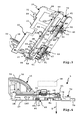
- a hand-held power tool 10 has a machine housing 11, in which a drive motor 12 is provided for driving a tool holder 13. At the tool holder 13, a tool 14 is detachably fastened, for example, a saw blade or other cutting tool.
- the hand-held machine tool is, for example, a saw or, more generally, a cutting machine.
- the machine housing 11 is provided with a handle 15 on which a switch 16 for switching on or off of the drive motor 12 is arranged.
- a connection for an energy store 17, for example a battery pack is provided on the machine housing 11 in order to supply the drive motor 12 or, more generally, the hand-held power tool 10 with electrical energy.
- a power supply with a power cord for connection to an electrical power grid is readily possible, but not shown.
- the tool 14 is protected by an upper, fixed cover 18 and below by a movable cover 19, which can pivot in the region of the fixed cover 18.
- the handheld power tool 10 is a reciprocating saw, i. in that the movable cover 19 can pivot to or under the fixed cover 18 in order to release the lower region of the saw blade or tool 14 for a saw cut or separating cut.
- a guide member 20 is provided at the bottom of the machine housing 11.
- the guide element 20 is plate-like and forms a guide plate 21.
- the tool 14 is provided in the working direction A on the right side 22, while the energy storage 17 is in the region of a left side 23 and a back 25 of the guide member 20.
- a front side 24 of the guide element 20 is in the direction of A front.
- the machine housing 11 is thus arranged on the upper side 26 of the guide element 20, while the underside of the guide element 20 forms a guide surface 27.
- a handle 28 is provided, with which the hand-held power tool 10 can be conveniently gripped and guided in addition to the handle 15 by an operator.
- the handle 28 is configured, for example, in the manner of a knob, so that it can be comfortably grasped by an operator.
- the operator may press the handle 28 with his palm.
- the gag is arranged on a pillar-like carrier, which projects upwards in front of the upper side 26 of the guide plate 21 / of the guide element 20.
- the hand-held power tool 10 and the guide rail 70 form a guide system 5.
- the hand-held power tool 10 is to be guided along the guide rail 70 in a working direction A, namely in the direction of a longitudinal axis L, in order to introduce cuts into a workpiece (not shown).
- miter bearing 30 By means of a miter bearing 30, bevel cuts can be made in the workpiece.
- the machine housing 11 and thus the tool holder 13 can namely indicated by an arrow G pivot about a miter axis GA.
- the miter bearing 30 is in two parts and comprises two upwardly in front of the top 26 of the guide member 20 projecting bearing elements 31, 32 and guided to these bearing elements 33, 34, which are connected to the machine housing 11.
- the guide element 20 slides with its underside guide surface 27 along an upper-side guide surface 76 of the guide rail 70 along.
- the guide rail has a rail body 71, at its working direction A right side 72, the tool 14 is moved along.
- the right side 72 forms a cutting edge, so to speak. It is preferably provided that the right side 72, which may be arranged, for example, a rubber lip or the like, is shortened with a first saw cut of the tool 14. Before the left in the direction of A side 73, the hand-held machine tool 10 is preferably not, which could well be the case.
- a front side 74 or a back side 75 of the guide rail 70 or both may be perpendicular or, as in the case of the back 75 of the case, not perpendicular obliquely to the right and left sides 72, 73, so that the guide rail 70, for example, to a slanted workpiece with its end faces, namely the front 74 and / or the back 75, can be applied.
- retaining groove 78 On the left side 73 of the guide rail 70 in the direction of operation, for example, a downwardly open, to the bottom 77 of the guide rail 70 open retaining groove 78 is provided. This can serve, for example, to hold a carriage, not shown in the drawing or a return spring. An attachment to a substrate with, for example, in the retaining groove 78 introduced retaining elements, such as screws, clamps or the like, is conceivable without further ado. Another, arranged next to the retaining groove 78, retaining groove 79 is open at the side and can, for example, also serve for attaching retaining means or represent an additional support and / or leadership for a return spring, a carriage or the like.
- the longitudinal guide projection 81 guides the guide element 20 transversely to the working direction A in a transverse direction Q, which runs parallel to the planes of the guide surfaces 27, 76.
- the longitudinal guide projection 81 has, for example, an upper wall surface 82, which is opposite a bottom 50 of the longitudinal guide receptacle 41.
- the wall surface 82 may, but need not, be in touch contact with the floor 50.
- the transverse guide with respect to the transverse direction Q make namely side walls 83, 84 of the longitudinal guide projection 81, the wall surface 82 at an angle, in the present case are at right angles.
- Guide ribs may protrude in front of the side walls 83, 84, so that the contact with the longitudinal guide receptacle 51 is only linear or punctiform.
- the longitudinal guide projection 81 in cross-section U-shaped, while the longitudinal guide receptacle 41 is complementary thereto also in cross-section U-shaped (transverse to the longitudinal axis L).
- the longitudinal guide projection 81 is integral with the rail body 71.
- the rail body 71 is for example made of plastic or metal or both, so it is rigid and immovable.
- adjusting devices 42 are provided in order to create a setting options in the transverse direction Q, that is to say to design the guidance of the guide element 20 in the transverse direction Q with as little play as possible.
- an adjusting device is provided on the guide element 20 and thus of the hand-held power tool 10.
- the guide rail also provides adjustment possibilities, so that, for example, at least one of the two side walls 83, 84 can be adjusted to or away from the other side wall.
- two adjustment devices 42 are provided on the guide element 20.
- the adjustment means 42 comprise guide bodies 43, 44 whose guide surfaces face each other.
- the guide bodies 43, 44 are designed, for example, in the manner of guide jaws.
- the other, opposite guide body 44 is adjustable to adjust the transverse distance to the opposite guide body 43. It is advantageous that the guide bodies 43, 44 are exchangeable guide bodies, ie that they can be easily replaced when worn. Furthermore, to set different transverse widths of the longitudinal guide receptacle 41 also not shown in the drawing alternative guide body 43, 44 may be provided.
- the guide bodies 43, 44 are detachably mountable in holding receptacles 45, 46 of the guide element 20, eg hooked, latched with the holding receivers 45, 46, screwed or the like.
- the movable, adjustable guide body 44 have a bulbous illustrated in the drawing adjustable and / or flexible portion on which from the back, that is from the longitudinal guide holder 41 side facing away, an adjusting body 47 acts.
- the adjusting body 47 comprises, for example, an eccentric element, which is mounted rotatably with respect to the guide element 20 on a rotary bearing 48. From the upper side 26, the adjusting bodies 47 can be actuated by means of a manual actuating element 49, so that the operator in this way can adjust the guide bodies 44 towards or away from the opposite guide bodies 43.
- so-called plunge cuts or chop cuts in which the tool 14 (saw blade) pivots about the axis SA and penetrates or plunges into the workpiece, can be readily carried out, since not only during the plunging movement of the tool 14 into the workpiece, the guide surfaces 27, 76 so to speak are pressed against each other, but also remain close to each other when exiting the workpiece, although perhaps the contact between the guide surfaces 27, 76 is briefly interrupted. Furthermore, this measure contributes to taking, for example, the hand-held machine tool on one or both of the handles 15, 28 and without the guide rail 70 to keep separate transport, for example, bring from one place of work to another place of work can.
- the rear grip structures 60a, 60b, 60c are arranged one behind the other with respect to the longitudinal axis L.
- the rear engagement structures 60a, 60c are arranged in the region of the front side 24 and the rear side 25 and the rear engagement structure 60c is between the two other rear engagement structures 60a, 60c with respect to the longitudinal axis L, so to speak ,
- the rear grip structures 60 a, 60 b, 60 c are arranged on a rear gripping receptacle 55 of the guide element 20 of the hand-held machine tool 10.
- the rear gripping receptacle 55 comprises a longitudinal groove 54 extending in the direction of the longitudinal axis L, in which the rear gripping projection 85 engages.
- the longitudinal groove 54 is substantially U-shaped and has a bottom 56 and to the bottom 56 angled side surfaces 57, 58 on.
- the rear engagement projection 85 which in the present case has an elongated shape extending in the direction of the longitudinal axis L, is not in touching contact with the side surfaces 57, 58 with its transverse sides.
- the insertion of the guide element 20 into the rear engagement projection 85 is facilitated, for example, by insertion receptacles 59 provided in the region of the front side 24 and the rear side 25 of the guide element 20.
- insertion bevels 62 are provided which facilitate a Aufgleisen the Hintergreif application 55 on the Hintergreifvorsprung 85.
- the Schugreifschenkel 61 define the Hintergreifability 55 in cross-section T-shaped.
- This contour fits exactly to the also T-shaped cross-sectional contour of the Hintergreifvorsprungs 85, which has a front of the guide surface 76 protruding support legs 86, projecting from the side retaining leg 87.
- the holding leg 87 engage behind the Schugreifschenkel 61, so they engage in the spaces between the Schugreifschenkeln 61 and the bottom 56 of the longitudinal groove.
- T-shaped undercut structures can be provided instead of the T-shaped undercut structures.
- an L-shaped configuration is possible in which, for example, one of the two retaining legs 87 would not be present.
- FIG. 4 Another alternative is with a rearward projection 185 in FIG. 4 indicated, which has a Y-shaped form.
- a plurality of transverse gripping Q arranged side by side Schugreifpatenteden may be provided, for example, both the Schugreifvorsprung 85 with the associated Schugreifpatenteden of the guide member 20 and the Schugreifvorsprung 185, the corresponding complementary, the drawing not closer than lines has resolved rear grip structures of a rear grip mount 155.
- a clearance 63 is preferably provided on the guide member 20.
- the Hintergreifschenkel 61 are free to the top 26 of the guide member 20.
- the bottom 56 of the rear gripping receptacle 55 is not continuous, but has an interruption in the region of the Schugreifschenkel 61.
- This measure is particularly advantageous for the production of the guide element 20, namely because the guide element 20 is more easily demoulded from moldings, not shown, which are provided for forming the top 26 and the bottom 27 of the guide member 20.
Abstract
Die Erfindung betrifft ein Führungssystem (5) umfassend eine ein Führungselement (20) aufweisende Hand-Werkzeugmaschine (10) und Führungsschiene (70), an deren Oberseite eine Schienen-Führungsfläche für eine Führungselement-Führungsfläche (27) an der Unterseite des Führungselements (20) der Hand-Werkzeugmaschine (10) vorgesehen ist, wobei an den Führungsflächen mindestens ein Längsführungsvorsprung (81) und mindestens eine Längsführungsaufnahme (41) zur Längsführung der Hand-Werkzeugmaschine entlang einer Längsachse (L) der Führungsschiene (70) vorgesehen sind und zwischen der Führungsschiene (70) und dem Führungselement (20) Hintergreifstrukturen vorhanden sind, die das Führungselement (20) in einer zu den Führungsflächen (27, 76) winkeligen, insbesondere rechtwinkeligen Tiefenrichtung (T) an der Führungsschiene (70) in einem Sinne halten, dass die Führungsflächen (27, 76) in Kontakt bleiben. Es ist vorgesehen, dass die Hintergreifstrukturen mindestens einen vor die Schienen-Führungsfläche vorstehenden Hintergreifvorsprung (85) zum Eingriff in mindestens eine sich an der Führungselement-Führungsfläche (27) parallel zu der Längsachse (L) erstreckende Hintergreifaufnahme (55) umfassen, wobei der mindestens eine Hintergreifvorsprung (85) parallel zu der Längsachse (L) verläuft und/oder einen Bestandteil einer Anordnung von parallel zu der Längsachse (L) hintereinander angeordneten Hintergreifvorsprüngen bildet und die mindestens eine Hintergreifaufnahme (55) sich parallel zu der Längsachse (L) erstreckt oder einen Bestandteil einer Anordnung von parallel zu der Längsachse (L) hintereinander angeordneten Hintergreifaufnahmen (55) bildet.The invention relates to a guide system (5) comprising a manual machine tool (10) and guide rail (70) having a guide element (20) on the upper side of which a rail guide surface for a guide element guide surface (27) on the underside of the guide element (20 ) of the hand-held machine tool (10) is provided, wherein at the guide surfaces at least one longitudinal guide projection (81) and at least one longitudinal guide receptacle (41) for longitudinal guidance of the hand-held machine tool along a longitudinal axis (L) of the guide rail (70) are provided and between the Guide rail (70) and the guide element (20) Hintergreifstrukturen are present, which hold the guide element (20) in an angle to the guide surfaces (27, 76) angled, in particular rectangular depth direction (T) on the guide rail (70) in a sense that the guide surfaces (27, 76) remain in contact. It is provided that the rear grip structures comprise at least one rear engagement projection (85) projecting in front of the rail guide surface for engagement in at least one rear engagement receptacle (55) extending parallel to the longitudinal axis (L) on the guide element guide surface (27) a rear engagement projection (85) runs parallel to the longitudinal axis (L) and / or forms part of an arrangement of rear engagement projections arranged one behind the other parallel to the longitudinal axis (L) and the at least one rear engagement receiver (55) extends parallel to the longitudinal axis (L) or forms part of an arrangement of parallel to the longitudinal axis (L) arranged behind one another rear gripping receptacles (55).
Description
Die Erfindung betrifft ein Führungssystem umfassend eine ein Führungselement aufweisende Hand-Werkzeugmaschine und eine mit ihrer Unterseite auf einen Untergrund auflegbare Führungsschiene, an deren Oberseite eine Schienen-Führungsfläche für eine Führungselement-Führungsfläche an der Unterseite des Führungselements der Hand-Werkzeugmaschine vorgesehen ist, wobei an den Führungsflächen mindestens ein Längsführungsvorsprung und mindestens eine Längsführungsaufnahme vorgesehen sind, die zur Längsführung der Hand-Werkzeugmaschine entlang einer Längsachse der Führungsschiene und des Führungselements ineinander eingreifen, und wobei zwischen der Führungsschiene und dem Führungselement Hintergreifstrukturen vorhanden sind, die das Führungselement in einer zu den Führungsflächen winkeligen, insbesondere rechtwinkeligen, Tiefenrichtung an der Führungsschiene in einem Sinne halten, dass die Führungsflächen in Kontakt bleiben.The invention relates to a guide system comprising a manual tool machine having a guide element and a guide rail which can be laid with its underside on a substrate, on whose upper side a rail guide surface is provided for a guide element guide surface on the underside of the guide element of the hand machine tool the guide surfaces at least one longitudinal guide projection and at least one longitudinal guide receptacle are provided which engage the longitudinal guide of the hand-held machine tool along a longitudinal axis of the guide rail and the guide element, and wherein between the guide rail and the guide element Hintergreifstrukturen are present, the guide element in one of the guide surfaces angular, in particular rectangular, keep the depth direction of the guide rail in a sense that the guide surfaces remain in contact.
Ein derartiges Führungssystem ist beispielsweise in
Ausgehend davon ist es die Aufgabe der vorliegenden Erfindung, ein Führungssystem bereitzustellen, das eine gute Längsführung der Hand-Werkzeugmaschine entlang der Führungsschiene ermöglicht und gleichzeitig der Hand-Werkzeugmaschine bezüglich der Führungsschiene in der Tiefenrichtung guten Halt bietet.Based on this, it is the object of the present invention to provide a guide system which allows a good longitudinal guidance of the hand-held machine tool along the guide rail and at the same time provides the hand-held machine tool with respect to the guide rail in the depth direction good grip.
Zur Lösung der Aufgabe ist bei einem Führungssystem für eine Hand-Werkzeugmaschine der eingangs genannten Art vorgesehen, dass die Hintergreifstrukturen mindestens einen vor die Schienen-Führungsfläche vorstehenden Hintergreifvorsprung zum Eingriff in mindestens eine sich an der Führungselement-Führungsfläche parallel zu der Längsachse erstreckende Hintergreifaufnahme umfassen, wobei der mindestens eine Hintergreifvorsprung parallel zu der Längsachse verläuft und/oder einen Bestandteil einer Anordnung von parallel zu der Längsachse hintereinander angeordneten Hintergreifvorsprüngen bildet und die mindestens eine Hintergreifaufnahme sich parallel zu der Längsachse erstreckt oder einen Bestandteil einer Anordnung von parallel zu der Längsachse hintereinander angeordneten Hintergreifaufnahmen bildet.To achieve the object, it is provided in a guide system for a hand-held machine tool of the type mentioned above that the rear grip structures comprise at least one rear engagement projection projecting in front of the rail guide surface for engagement in at least one rear engagement mount extending parallel to the longitudinal axis on the guide element guide surface, wherein the at least one Hintergreifvorsprung runs parallel to the longitudinal axis and / or forms part of an array of parallel to the longitudinal axis behind the other arranged Hintergreifvorsprüngen and the at least one Hintergreifaufnahme extending parallel to the longitudinal axis or a component of an array of parallel to the longitudinal axis successively arranged behind gripping recordings forms.
Neben dem Führungssystem als Ganzes umfasst die Erfindung auch die Hand-Werkzeugmaschine in der für die Führungsschiene, die sich dann wie folgt definieren lässt:
- Hand-Werkzeugmaschine mit einem Führungselement für eine mit ihrer Unterseite auf einen Untergrund auflegbare Führungsschiene, an deren Oberseite eine Schienen-Führungsfläche für eine Führungselement-Führungsfläche an der Unterseite des Führungselements der Hand-Werkzeugmaschine vorgesehen ist, wobei an den Führungsflächen mindestens ein Längsführungsvorsprung und mindestens eine Längsführungsaufnahme vorgesehen sind, die zur Längsführung der Hand-Werkzeugmaschine entlang einer Längsachse der Führungsschiene und des Führungselements ineinander eingreifen, und wobei zwischen der Führungsschiene und dem Führungselement Hintergreifstrukturen vorhanden sind, die das Führungselement in einer zu den Führungsflächen winkeligen, insbesondere rechtwinkeligen Tiefenrichtung an der Führungsschiene in einem Sinne halten, dass die Führungsflächen in Kontakt bleiben, wobei die Hintergreifstrukturen mindestens einen vor die Schienen-Führungsfläche vorstehenden Hintergreifvorsprung zum Eingriff in mindestens eine sich an der Führungselement-Führungsfläche parallel zu der Längsachse erstreckende Hintergreifaufnahme umfassen, wobei die mindestens eine Hintergreifaufnahme sich parallel zu der Längsachse erstreckt oder einen Bestandteil einer Anordnung von parallel zu der Längsachse hintereinander angeordneten Hintergreifaufnahmen bildet und zum Eingriff des mindestens einen Hintergreifvorsprungs ausgestaltet ist, der parallel zu der Längsachse verläuft und/oder einen Bestandteil einer Anordnung von parallel zu der Längsachse hintereinander angeordneten Hintergreifvorsprüngen bildet.
- Hand machine tool with a guide element for a laying on its underside on a base guide rail, at the top of a rail guide surface is provided for a guide element guide surface on the underside of the guide element of the hand-held machine tool, wherein at the guide surfaces at least one longitudinal guide projection and at least a longitudinal guide receptacle are provided, which engage the longitudinal guide of the hand-held machine tool along a longitudinal axis of the guide rail and the guide element, and wherein between the guide rail and the guide element Hintergreifstrukturen are present, the guide element in an angle to the guide surfaces, in particular rectangular depth direction of the Hold guide rail in a sense that the guide surfaces remain in contact, wherein the rear grip structures at least one before the rail guide surface protruding Hintergre The projection for engaging in at least one on the guide element guide surface parallel to the longitudinal axis extending rear engagement receptacle, wherein the at least one Hintergreifaufnahme extending parallel to the longitudinal axis or part of an array of parallel to the longitudinal axis is arranged behind one another arranged behind gripping recordings and designed for engagement of the at least one Hintergreifvorsprungs which extends parallel to the longitudinal axis and / or forms part of an array of parallel to the longitudinal axis of successively arranged rear engagement projections.
Eine ebenfalls im Rahmen der Erfindung liegende Führungsschiene für ein derartiges Führungssystem lässt sich wie folgt definieren:
- Führungsschiene, die mit ihrer Unterseite auf einen Untergrund auflegbar ist und an ihrer Oberseite eine Schienen-Führungsfläche für eine Führungselement-Führungsfläche an der Unterseite eines Führungselements einer Hand-Werkzeugmaschine aufweist, wobei an den Führungsflächen mindestens ein Längsführungsvorsprung und mindestens eine Längsführungsaufnahme vorgesehen sind, die zur Längsführung der Hand-Werkzeugmaschine entlang einer Längsachse der Führungsschiene und des Führungselements ineinander eingreifen, und wobei zwischen der Führungsschiene und dem Führungselement Hintergreifstrukturen vorhanden sind, die das Führungselement in einer zu den Führungsflächen winkeligen, insbesondere rechtwinkeligen, Tiefenrichtung an der Führungsschiene in einem Sinne halten, dass die Führungsflächen in Kontakt bleiben, wobei die Hintergreifstrukturen mindestens einen vor die Schienen-Führungsfläche vorstehenden Hintergreifvorsprung zum Eingriff in mindestens eine sich an der Führungselement-Führungsfläche parallel zu der Längsachse erstreckende Hintergreifaufnahme umfassen, wobei der mindestens eine Hintergreifvorsprung parallel zu der Längsachse verläuft und/oder einen Bestandteil einer Anordnung von parallel zu der Längsachse hintereinander angeordneten Hintergreifvorsprüngen bildet und zum Eingriff in die mindestens eine Hintergreifaufnahme vorgesehen ist, die sich parallel zu der Längsachse erstreckt oder einen Bestandteil einer Anordnung von parallel zu der Längsachse hintereinander angeordneten Hintergreifaufnahmen bildet.
- Guide rail, which is placed with its underside on a substrate and at its top a rail guide surface for a guide element guide surface on the underside of a guide element of a hand-held machine tool, wherein on the guide surfaces at least one longitudinal guide projection and at least one longitudinal guide receptacle are provided engage the longitudinal guide of the hand-held machine tool along a longitudinal axis of the guide rail and the guide element, and wherein between the guide rail and the guide element Hintergreifstrukturen are present, which hold the guide element in an angle to the guide surfaces, in particular rectangular, depth direction of the guide rail in one sense in that the guide surfaces remain in contact, wherein the rear grip structures comprise at least one rear engagement projection projecting in front of the rail guide surface for engagement in at least one of them the at least one Hintergreifvorsprung extending parallel to the longitudinal axis and / or forms part of an array of parallel to the longitudinal axis behind the other arranged Hintergreifvorsprüngen and is provided for engagement in the at least one Hintergreifaufnahme on the guide element guide surface parallel to the longitudinal axis which extends parallel to the longitudinal axis or forms part of an array of mutually parallel to the longitudinal axis arranged behind each other Hintergreifaufnahmen.
Bei den erfindungsgemäßen Komponenten (Hand-Werkzeugmaschine und Führungsschiene) und dem Führungssystem als Ganzes ist es ein Grundgedanke, dass der Längsführungsvorsprung und die Längsführungsaufnahme für die Längsführung entlang der Längsachse vorgesehen sind und davon separat die Hintergreifstrukturen, die in Bezug auf die Tiefenrichtung dem System bestehend aus Führungsschiene und Hand-Werkzeugmaschine Halt bieten, wobei der oder die Hintergreifvorsprünge vor die Führungsfläche der Führungsschiene vorstehen und die Hintergreifaufnahme direkt an der Führungselement-Führungsfläche der Hand-Werkzeugmaschine angeordnet ist, insbesondere nicht vor diese vorsteht. Somit kann die Hand-Werkzeugmaschine ohne weiteres auch mit Führungsschienen oder Führungslinealen verwendet werden, die keinen Hintergreifvorsprung haben, also beispielsweise zum Längsführen von sozusagen konventionellen Hand-Werkzeugmaschinen dienen.In the components according to the invention (hand-held machine tool and guide rail) and the guidance system as a whole, it is a basic idea in that the longitudinal guide projection and the longitudinal guide receptacle are provided for the longitudinal guide along the longitudinal axis and separately the Hintergreifstrukturen which provide support in relation to the depth direction of the system consisting of guide rail and hand machine tool, said or the Hintergreifvorsprünge projecting in front of the guide surface of the guide rail and the rear grip mount is arranged directly on the guide element guide surface of the hand machine tool, in particular not projecting in front of it. Thus, the hand-held machine tool can be readily used with guide rails or guide rulers that have no Hintergreifvorsprung, so for example for longitudinal guidance of so-called conventional hand-machine tools serve.
Bei der Hand-Werkzeugmaschine handelt es sich vorzugsweise um eine Sägemaschine, insbesondere um eine Tauchsäge oder eine Kappsäge oder eine Pendelhaubensäge. Aber auch andere Hand-Werkzeugmaschinen, zum Beispiel Fräsmaschinen, Schleifmaschinen oder dergleichen, können auf diesem Wege geführt werden. Die Hand-Werkzeugmaschine ist vorzugsweise eine Trenn-Hand-Werkzeugmaschine. Bei dem Werkzeug handelt es sich also vorzugsweise um ein Trennwerkzeug, beispielsweise um ein Sägeblatt.The manual machine tool is preferably a sawing machine, in particular a submersible saw or a chop saw or a pendulum hood saw. But other manual machine tools, such as milling machines, grinding machines or the like, can be performed in this way. The hand machine tool is preferably a separating hand machine tool. The tool is thus preferably a cutting tool, for example a saw blade.
Die Hand-Werkzeugmaschine weist beispielsweise einen elektrischen oder pneumatischen Antriebsmotor auf. Vorzugsweise ist die Hand-Werkzeugmaschine mit einem Energiespeicher, zum Beispiel einem Akkupack, versehen, so dass sie unabhängig von einem elektrischen Energieversorgungsnetz betrieben werden kann. Aber auch eine kabelgebundene Hand-Werkzeugmaschine, d.h. eine Hand-Werkzeugmaschine mit einem Anschlusskabel für ein elektrisches Energieversorgungsnetz, ist ohne weiteres möglich.The hand-held power tool has, for example, an electric or pneumatic drive motor. Preferably, the hand-held machine tool is provided with an energy store, for example a battery pack, so that it can be operated independently of an electrical power supply network. But also a wired hand machine tool, i. a hand-held power tool with a connection cable for an electrical power supply network is readily possible.
Beispielsweise ist der Längsführungsvorsprung im Querschnitt U-förmig und die Längsführungsaufnahme ebenfalls im Querschnitt U-förmig. Es ist bevorzugt, wenn der Längsführungsvorsprung, insbesondere eine Längsrippe, nach oben vor die Schienen-Führungsfläche vorsteht, während die Längsführungsaufnahme, insbesondere eine Längsnut oder ein Längsschlitz, sozusagen als eine Vertiefung oder ein Rücksprung an der Unterseite des Führungselements, nämlich der Führungselement-Führungsfläche, ausgestaltet ist.For example, the longitudinal guide projection in cross-section U-shaped and the longitudinal guide receptacle also in cross-section U-shaped. It is preferred if the longitudinal guide projection, in particular a longitudinal rib, protrudes upward in front of the rail guide surface, while the longitudinal guide receptacle, in particular a longitudinal groove or a longitudinal slot, as it were as a recess or a recess on the underside of the guide element, namely the guide element guide surface, is configured.
Das Führungssystem eignet sich beispielsweise für sogenannte Kappschnitte. Weil die Führungsschiene an der Hand-Werkzeugmaschine, beispielsweise der Säge, verbleibt, kann diese an den jeweiligen Einsatzort zusammen mit der Hand-Werkzeugmaschine gebracht werden, d.h. der Bediener ergreift beispielsweise nur die Hand-Werkzeugmaschine und nimmt dabei gleichzeitig die Führungsschiene mit, um sie beispielsweise an einem Werkstück, insbesondere einem Holzstück, anzulegen.The guide system is suitable, for example, for so-called cross cuts. Because the guide rail remains on the hand machine tool, such as the saw, it can be brought to the respective job site together with the hand machine tool, i. For example, the operator grips only the hand-held machine tool and at the same time takes along the guide rail in order to apply it, for example, to a workpiece, in particular a piece of wood.
Die Schienen-Führungsfläche und die Führungselement-Führungsfläche liegen zweckmäßigerweise im Wesentlichen über die gesamte Querbreite des Führungselements zumindest im Wesentlichen flächig aneinander an.The rail guide surface and the guide element guide surface are expediently substantially flat against one another over substantially the entire transverse width of the guide element.
Bevorzugt ist es, wenn die Schienen-Führungsfläche und die Führungselement-Führungsfläche quer zur Längsachse an beiden Seiten des mindestens einen Hintergreifvorsprungs und der mindestens einen Hintergreifaufnahme in einem insbesondere flächigen Führungskontakt sind.It is preferred if the rail guide surface and the guide element guide surface are transverse to the longitudinal axis on both sides of the at least one rear gripping projection and the at least one rear gripping receptacle in a particular planar guide contact.
Die mindestens eine Hintergreifaufnahme hat vorzugsweise einen Querabstand zu beiden Queraußenseiten des Führungselements. In anderen Worten ist die mindestens eine Hintergreifaufnahme zweckmäßigerweise zwischen den Queraußenseiten des Führungselements angeordnet.The at least one Hintergreifaufnahme preferably has a transverse distance to both transverse outer sides of the guide element. In other words, the at least one rear engagement seat is expediently arranged between the transverse outer sides of the guide element.
Bevorzugt ist die mindestens eine Hintergreifaufnahme als ein Rücksprung ausgestaltet, d.h. sie steht nicht vor die Führungselement-Führungsfläche vor.Preferably, the at least one rear engagement receptacle is configured as a return, i. it is not available in front of the guide element guide surface.
Bezüglich der Querbreite des Führungselements können beispielsweise zwei oder weitere Hintergreifaufnahmen in einem Querabstand zueinander vorgesehen sein.With regard to the transverse width of the guide element, for example, two or more rear engagement receptacles may be provided at a transverse distance from one another.
Bezüglich des Hintergreifvorsprungs und der Hintergreifaufnahme sind mehrere Querschnittskonturen denkbar. Beispielsweise ist der Hintergreifvorsprung ebenso wie die Hintergreifaufnahme im Querschnitt T-förmig, L-förmig oder Y-förmig. Es können auch einer oder mehrere derartige Querschnitte aufweisende Hintergreifabschnitte vorgesehen sein. Ferner ist es möglich, dass der mindestens eine Hintergreifvorsprung und die mindestens eine Hintergreifaufnahme Schwalbenschwanzkonturen aufweisen oder mit Schwalbenschwanzkonturen ineinander eingreifen.With regard to the rearward projection and the rear engagement reception, a plurality of cross-sectional contours are conceivable. For example, the Hintergreifvorsprung as well as the Hintergreifaufnahme in cross-section T-shaped, L-shaped or Y-shaped. It can also be provided one or more such cross-sections having Hintergreifabschnitte. Furthermore, it is possible for the at least one rear engagement projection and the at least one rear engagement receiver to have dovetail contours or to engage with dovetail contours.
Der mindestens eine Hintergreifvorsprung kann z.B. pilzförmig sein. Es ist auch möglich, dass mehrere pilzförmige Hintergreifvorsprünge in Richtung der Längsachse hintereinander an der Schienen-Führungsfläche angeordnet sind.The at least one rearward projection may be e.g. be mushroom-shaped. It is also possible that a plurality of mushroom-shaped rear engagement projections are arranged one behind the other in the direction of the longitudinal axis on the rail guide surface.
Vorteilhaft ist es, wenn die Hintergreifaufnahme den mindestens einen Hintergreifvorsprung gabelförmig aufnimmt.It is advantageous if the rear gripping receptacle receives the at least one rear gripping projection fork-shaped.
Die mindestens eine Hintergreifaufnahme des Führungselements der Hand-Werkzeugmaschine ist vorzugsweise an einem Längsschlitz oder an einer Längsnut angeordnet, die sich parallel zu der Längsachse des Führungselements erstreckt. Die Hintergreifaufnahme wird von mindestens einem Hintergreifschenkel begrenzt, der in einen Innenraum des Längsschlitzes oder der Längsnut zum Hintergreifen des mindestens einen Hintergreifvorsprungs vorsteht. Bevorzugt sind einander gegenüberliegende Hintergreifschenkel vorgesehen, die jeweils einen Hintergriff des mindestens einen Hintergreifvorsprungs ermöglichen. Zwischen den beiden Hintergreifschenkeln ist dann beispielsweise ein Schlitz vorgesehen, durch den hin durch ein nachfolgend noch erläuterter Tragschenkel des Hintergreifvorsprungs oder der Hintergreifvorsprünge hindurchtreten kann.The at least one rear engagement receptacle of the guide element of the hand-held machine tool is preferably arranged on a longitudinal slot or on a longitudinal groove which extends parallel to the longitudinal axis of the guide element. The Hintergreifaufnahme is limited by at least one Hintergreifschenkel which protrudes into an interior of the longitudinal slot or the longitudinal groove for engaging behind the at least one Hintergreifvorsprungs. Preferably, opposing Hintergreifschenkel are provided which each allow a rear grip of the at least one Hintergreifvorsprungs. For example, a slot is provided between the two Hintergreifschenkeln through which can pass through a subsequently explained support legs of Hintergreifvorsprungs or Hintergreifvorsprünge.
Eine vorteilhafte Maßnahme sieht vor, dass der Boden der Längsnut oder des Längsschlitzes im Bereich des mindestens einen Hintergreifschenkels unterbrochen ist bzw. zur Oberseite des Führungselements offen ist, was eine leichtere Entformung des Führungselements aus einem Gusswerkzeug ermöglicht.An advantageous measure provides that the bottom of the longitudinal groove or the longitudinal slot in the region of the at least one Hintergreifschenkels is interrupted or is open to the top of the guide member, which allows easier removal of the guide element from a casting tool.
Eine Unterseite des mindestens einen Hintergreifschenkels ist vorzugsweise mit der Führungselement-Führungsfläche einstückig oder fluchtet mit dieser. Es ist auch möglich, dass der Hintergreifschenkel einen Abstand zu der Führungselement-Führungsfläche hat, jedenfalls nicht vor die Führungselement-Führungsfläche, bei Gebrauch in der Regel nach unten, nämlich zur Schiene-Führungsfläche der Führungsschiene hin, vorsteht.An underside of the at least one rear gripping leg is preferably integral with or aligned with the guide element guide surface. It is also possible that the Hintergreifschenkel has a distance to the guide element guide surface, at least not in front of the guide element guide surface, in use usually down, namely the rail guide surface of the guide rail out, protruding.
Der mindestens eine Hintergreifvorsprung weist zweckmäßigerweise einen vor die Schienen-Führungsfläche vorstehenden Tragschenkel auf. Beispielsweise steht der Tragschenkel rechtwinkelig von der Schienen-Führungsfläche ab, bei Gebrauch in der Regel beispielsweise nach oben. Von dem Tragschenkel steht mindestens ein Halteschenkel winkelig, beispielsweise rechtwinkelig oder auch stumpfwinkelig oder spitzwinkelig zum Hintergreifen der mindestens einen Hintergreifaufnahme des Führungselements der Hand-Werkzeugmaschine ab.The at least one rear engagement projection expediently has a support leg projecting in front of the rail guide surface. For example, the support leg is perpendicular from the rail guide surface, in use, for example, usually upwards. From the supporting leg is at least one holding leg angled, for example at right angles or obtuse or acute angled for engaging behind the at least one rear engagement of the guide element of the hand-machine tool.
Die Hintergreifstrukturen, beispielsweise der vorgenannte Hintergreifschenkel oder der Halteschenkel oder beide, weisen zweckmäßigerweise mindestens eine Einführschräge auf. Die Einführschräge umfasst beispielsweise Rundungen, Schrägflächen, Trichterflächen oder dergleichen. Jedenfalls ist bevorzugt, wenn die Schrägfläche oder Einführschräge bezüglich der Längsachse schräg verläuft. Somit können die Hintergreifstrukturen leichter in Eingriff miteinander gebracht werden.The Hintergreifstrukturen, for example, the aforementioned Hintergreifschenkel or the holding leg or both, expediently have at least one insertion bevel. The insertion bevel includes, for example, curves, bevels, funnel surfaces or the like. In any case, it is preferred if the inclined surface or insertion bevel is inclined with respect to the longitudinal axis. Thus, the rear grip structures can be easily brought into engagement with each other.
An dieser Stelle sei bemerkt, dass es vorteilhaft ist, wenn die Führungsschiene stirnseitig offen ist. Dadurch ist es z.B. möglich, das Führungselement der Hand-Werkzeugmaschine, beispielsweise ein Sägetisch oder eine Führungsplatte, von der Stirnseite her sozusagen auf die Führungsschiene aufzufädeln oder aufzugleisen oder einzugleisen.It should be noted that it is advantageous if the guide rail is open at the front. Thereby it is e.g. possible to thread the guide element of the hand-held machine tool, for example a saw table or a guide plate, from the front side, as it were, onto the guide rail or pull it up or in to pull it in.
Das Führungselement der Hand-Werkzeugmaschine weist zweckmäßigerweise bezüglich der Längsachse in einem Abstand zueinander angeordnete Hintergreifstrukturen auf, beispielsweise zwei oder drei Hintergreifstrukturen. In dem Abstand sind zweckmäßigerweise keine den Hintergreifvorsprung der Führungsschiene hintergreifende Hintergreifkonturen vorgesehen. Somit ist es beispielsweise möglich, dass der mindestens eine Hintergreifvorsprung der Führungsschiene bezüglich der Tiefenrichtung frei in die oder eine Längsnut oder eines Längsschlitzes des Führungselements der Hand-Werkzeugmaschine einführbar ist.The guide element of the hand-held machine tool expediently has a rear engagement structure arranged at a distance from one another with respect to the longitudinal axis, for example two or three rear engagement structures. In the distance, no Hintergreifkonturen the rear engaging projection of the guide rail engages behind expediently. Thus, it is possible, for example, that the at least one Hintergreifvorsprung the guide rail with respect to the depth direction freely in the or a longitudinal groove or a Longitudinal slot of the guide element of the hand-held machine tool is insertable.
Die zueinander beabstandeten Hintergreifstrukturen des Führungselements sorgen zweckmäßigerweise an den notwendigen Stellen für den Halt der Hand-Werkzeugmaschine an der Führungsschiene in Bezug auf die Tiefenrichtung.The mutually spaced rear gripping structures of the guide element expediently provide at the necessary points for the maintenance of the hand-held machine tool on the guide rail with respect to the depth direction.
Vorzugsweise ist vorgesehen, dass in dem Abstand zwischen den Hintergreifstrukturen ein gewisses Bewegungsspiel zwischen der Führungsschiene und dem Führungselement möglich ist und/oder das in dem Abstand zwischen den Hintergreifstrukturen kein Kontakt zwischen Führungselement und Führungsschiene vorhanden ist. Dies kann dazu beitragen, dass sich das Führungselement an der Führungsschiene nicht verkantet.It is preferably provided that a certain play of motion between the guide rail and the guide element is possible in the distance between the rear engagement structures and / or that there is no contact between guide element and guide rail in the distance between the rear engagement structures. This can contribute to the fact that the guide element on the guide rail does not tilt.
In dem Abstand zwischen den Hintergreifstrukturen ist zweckmäßigerweise eine Nut des Führungselements, an welcher die Hintergreifstrukturen vorgesehen ist, zur Führungsschiene hin offen. Somit können auch sich eventuell in dieser Nut ansammelnde Späne, Stäube oder dergleichen, in dem Abstand zwischen den Hintergreifstrukturen aus der Nut heraus gelangen.In the distance between the rear gripping structures, a groove of the guide element, on which the rear gripping structures are provided, is expediently open towards the guide rail. Thus, even in this groove accumulating chips, dusts or the like, in the distance between the rear gripping structures out of the groove can get out.
Das Führungselement der Hand-Werkzeugmaschine umfasst zweckmäßigerweise zwei, vorzugsweise drei oder vier, in Bezug auf die Längsachse in einem Abstand zueinander angeordnete Hintergreifaufnahmen, wobei in dem Abstand der Hintergreifvorsprung oder die Anordnung der Hintergreifvorsprünge der Führungsschiene nicht durch eine Hintergreifaufnahme oder einen Hintergreifschenkel des Führungselements der Hand-Werkzeugmaschine hintergriffen ist oder in Bezug auf die Tiefenrichtung keine Abstützung an dem Führungselement hat.The guide element of the hand-held machine tool expediently comprises two, preferably three or four, with respect to the longitudinal axis at a distance from each other arranged Hintergreifaufnahmen, wherein in the distance of Hintergreifvorsprung or the arrangement of Hintergreifvorsprünge the guide rail not by a Hintergreifaufnahme or a Hintergreifschenkel of the guide element Hand machine tool is engaged behind or with respect to the depth direction has no support on the guide element.
In dem Abstand ist also vorteilhaft keine den Hintergreifvorsprung oder die Hintergreifvorsprünge der Führungsschiene hintergreifende Struktur vorhanden, so dass beispielsweise die bereits erwähnte Nut, in welche der Hintergreifvorsprung oder die Hintergreifvorsprünge eingreifen, zur Führungsschiene hin offen ist.In the distance so advantageously no behind the rear projection or the Hintergreifvorsprünge the guide rail engages behind structure so that, for example, the already mentioned groove, in which engage the Hintergreifvorsprung or Hintergreifvorsprünge to the guide rail is open.
Es ist aber auch möglich, dass in diesem Bereich zwar keine vollständige Öffnung vorhanden ist, sondern ein Schenkel oder sonstiger Vorsprung der Hintergreifstrukturen des Führungselements zu dem mindestens einen Hintergreifvorsprung der Führungsschiene vorsteht. Zwischen diesem Vorsprung der Hintergreifstrukturen des Führungselements und dem Hintergreifvorsprung der Führungsschiene ist jedoch in diesem Fall kein formschlüssiger Kontakt oder Kontakt im Sinne einer Abstützung bezüglich der Tiefenrichtung vorgesehen.But it is also possible that in this area, although no complete opening is present, but a leg or other projection of the rear gripping structures of the guide element protrudes to the at least one Hintergreifvorsprung the guide rail. However, in this case no positive contact or contact in the sense of a support with respect to the depth direction is provided between this projection of the rear gripping structures of the guide element and the Hintergreifvorsprung the guide rail.
Vorteilhaft ist vorgesehen, dass in Bezug auf die Längsachse am vorderen und hinteren Endbereich oder Längsendbereichen des Führungselements der Hand-Werkzeugmaschine jeweils eine Hintergreifaufnahme vorhanden ist. Zwischen diesen Hintergreifaufnahmen kann keine weitere Hintergreifaufnahme vorgesehen sein. Besonders bevorzugt ist jedoch längsmittig bezüglich der beiden vorgenannten, an Endbereichen oder Längsendbereichen des Führungselements angeordneten Hintergreifaufnahmen eine weitere Hintergreifaufnahmen vorgesehen, was auch in der Zeichnung dargestellt ist.Advantageously, it is provided that with respect to the longitudinal axis at the front and rear end region or longitudinal end regions of the guide element of the hand-held machine tool in each case a Hintergreifaufnahme is present. Between these Hintergreifaufnahmen no further Hintergreifaufnahme can be provided. With particular preference, however, a further rear engagement receptacle is provided longitudinally with respect to the two aforementioned rear engagement receptacles arranged at end regions or longitudinal end regions of the guide element, which is also illustrated in the drawing.
Zwischen den zueinander beabstandeten Hintergreifaufnahmen des Führungselements ist zweckmäßigerweise ein Freiraum vorhanden, in welchen der mindestens eine Hintergreifvorsprung oder die Hintergreifvorsprünge der Führungsschiene eingreifen können. Der Freiraum ist zweckmäßigerweise als eine Längsnut ausgestaltet, die sich in der Richtung der Längsachse erstreckt.Between the mutually spaced Hintergreifaufnahmen the guide element expediently a free space is available, in which the at least one Hintergreifvorsprung or Hintergreifvorsprünge the guide rail can intervene. The clearance is expediently designed as a longitudinal groove which extends in the direction of the longitudinal axis.
Der Freiraum hat zweckmäßigerweise eine Aufweitung, sodass nur die Hintergreifaufnahmen in Kontakt mit dem mindestens einen Hintergreifvorsprung der Führungsschiene sind.The space expediently has a widening, so that only the rear engagement seats are in contact with the at least one rear engagement projection of the guide rail.
Eine vorteilhafte Ausführungsform sieht vor, dass die Querführung quer zur Längsachse und quer zur Tiefenrichtung nicht von den Hintergreifstrukturen geleistet wird, sondern von dem Längsführungsvorsprung und der Längsführungsaufnahme. Es beispielsweise vorteilhaft, wenn einander zugewandte, sich parallel zu den Führungsflächen erstreckende Flächen des Längsführungsvorsprungs und der Längsführungsaufnahme oder auch des Hintergreifvorsprungs und der Hintergreifaufnahme nicht in einem Führungskontakt miteinander sind.An advantageous embodiment provides that the transverse guide transversely to the longitudinal axis and transversely to the depth direction is not provided by the rear gripping structures, but by the longitudinal guide projection and the longitudinal guide receptacle. For example, it is advantageous if mutually facing, parallel to the guide surfaces extending surfaces of the longitudinal guide projection and the longitudinal guide receptacle or the Hintergreifvorsprungs and the Hintergreifaufnahme are not in a management contact with each other.
Es ist zweckmäßigerweise vorgesehen, dass das Führungselement der Hand-Werkzeugmaschine quer zu der Längsachse und parallel zu den Führungsflächen ausschließlich durch den Längsführungsvorsprung und die Längsführungsaufnahme geführt ist. Das ist so zu verstehen, dass zwar partiell oder temporär ein Berührkontakt zwischen dem Hintergreifvorsprung und der Hintergreifaufnahme quer zur Längsachse, z.B. in Querrichtung parallel zu den Führungsflächen, vorhanden sein kann, dieser jedoch nicht eine wesentliche Quer-Führungsfunktion quer zur Längsachse parallel zu den Führungsflächen leistet oder leisten muss.It is expediently provided that the guide element of the hand-held machine tool is guided transversely to the longitudinal axis and parallel to the guide surfaces exclusively by the longitudinal guide projection and the longitudinal guide receptacle. This is to be understood that, although partially or temporarily, a contact contact between the Hintergreifvorsprung and the Hintergreifaufnahme and transversely to the longitudinal axis, e.g. in the transverse direction parallel to the guide surfaces, may be present, but this does not perform a significant transverse-guiding function transverse to the longitudinal axis parallel to the guide surfaces or afford.
Zweckmäßigerweise ist vorgesehen, dass an der Führungsschiene nur ein einziger sich in Richtung der Längsachse erstreckender Hintergreifvorsprung oder nur eine einzige Anordnung linear hintereinander entlang der Längsachse angeordneter Hintergreifvorsprünge vorgesehen ist.Appropriately, it is provided that on the guide rail only a single extending in the direction of the longitudinal axis Hintergreifvorsprung or only a single arrangement is provided linearly behind the other along the longitudinal axis arranged Hintergreifvorsprünge.
Bei dem Führungselement ist vorteilhaft, wenn nur eine sich in Richtung der Längsachse erstreckende Hintergreifaufnahme oder nur eine einzige Anordnung parallel zu der Längsachse hintereinander angeordneter Hintergreifvorsprünge vorhanden ist.In the guide element is advantageous if only one extending in the direction of the longitudinal axis Hintergreifaufnahme or only a single arrangement parallel to the longitudinal axis of successively arranged Hintergreifvorsprünge is present.
Eine bevorzugte Ausführungsform sieht vor, dass eine Einstelleinrichtung zur Verstellung eines Querabstands zwischen den in der vorgenannten Querrichtung, also in der parallel zu den Führungsflächen verlaufenden Richtung, führenden Flächen vorgesehen ist. Beispielsweise ist die Einstelleinrichtung zur Verstellung eines Querabstands zwischen einander gegenüberliegenden Führungsflächen der mindestens einen Längsführungsaufnahme oder zur Verstellung in einander entgegengesetzter und voneinander abgewandten Außenseiten des Längsführungsvorsprungs vorgesehen. In beiden Fällen kann die Querführung in der vorgenannten Querrichtung, also nicht der Tiefenrichtung, verbessert werden. Bevorzugt sind mehrere, beispielsweise zwei, Einstelleinrichtungen, die einen Längsabstand in Richtung der Längsachse haben.A preferred embodiment provides that an adjusting device is provided for adjusting a transverse distance between the leading in the aforementioned transverse direction, ie in the direction parallel to the guide surfaces, leading surfaces. For example, the adjusting device for adjusting a transverse distance between opposing guide surfaces of the at least one longitudinal guide receptacle or for adjustment in opposite and opposite outer sides of the longitudinal guide projection is provided. In both cases, the transverse guide in the aforementioned transverse direction, that is not the depth direction, can be improved. Preferred are a plurality, for example two, adjusting devices which have a longitudinal spacing in the direction of the longitudinal axis.
Bevorzugt ist es, wenn der mindestens eine Hintergreifvorsprung als eine Längsrippe ausgestaltet ist.It is preferred if the at least one rear engagement projection is designed as a longitudinal rib.
Eine günstige Ausführungsform der Erfindung sieht vor, dass der Hintergreifvorsprung etwa mittig zwischen sich parallel zur Längsrichtung erstreckenden Seiten, sozusagen Längsseiten, der Führungsschiene befindet. Auch bei der mindestens eine Hintergreifaufnahme ist eine mittige Anordnung vorteilhaft, d.h. dass sie etwa mittig zwischen sich parallel zur Längsrichtung erstreckenden Seiten, zum Beispiel Schmalseiten oder Längsseiten, des Führungselements der Hand-Werkzeugmaschine angeordnet ist.A favorable embodiment of the invention provides that the Hintergreifvorsprung is approximately centrally between parallel to the longitudinal direction extending sides, so to speak long sides, the guide rail. Even with the at least one rear engagement mount, a central arrangement is advantageous, i. that it is arranged approximately centrally between sides extending parallel to the longitudinal direction, for example narrow sides or longitudinal sides, of the guide element of the hand-held machine tool.
Zweckmäßigerweise ist vorgesehen, dass das Führungselement quer außen, also an den Längsseiten, nicht im Hintergriff mit der Führungsschiene ist, dort also keine Hintergreifstrukturen vorgesehen sind.Appropriately, it is provided that the guide element is transversely outward, ie on the longitudinal sides, not in the rear grip with the guide rail, so there are no Hintergreifstrukturen provided.
Vorzugsweise sind ausschließlich an der Führungselement-Führungsfläche eine oder mehrere Hintergreifaufnahmen vorgesehen, während die zur Arbeitsrichtung oder Längsachse parallelen Längsseiten ungeführt sind oder nur zur Führung in Richtung der Längsachse dienen.Preferably, one or more Hintergreifaufnahmen are provided exclusively on the guide element guide surface, while the parallel to the working direction or longitudinal axis longitudinal sides are unguided or only serve to guide in the direction of the longitudinal axis.
Die Hand-Werkzeugmaschine weist zweckmäßigerweise einen Handgriff zum Führen der Handwerkzeugmaschine auf. Bevorzugt erstreckt sich der Handgriff oberhalb der Längsführungsaufnahme oder des Längsführungsvorsprungs. Besonders bevorzugt ist auch eine Anordnung des Handgriffs oberhalb der Hintergreifaufnahme. Weiterhin ist es zweckmäßig, wenn der Handgriff in Arbeitsrichtung vorn angeordnet ist. Bevorzugt ist eine Anordnung unmittelbar vorn am Führungselement. Auf diese Weise kann jedenfalls der Benutzer im Bereich des Handgriffes Kraft auf das Führungselement ausüben und somit dazu beitragen, dass das Führungselement auf der Führungsschiene in Bezug auf die Tiefenrichtung optimal gehalten wird und/oder auch die Längsführung in Arbeitsrichtung bzw. entlang der Längsachse besonders gut gelingt.The hand-held machine tool expediently has a handle for guiding the hand-held power tool. Preferably, the handle extends above the longitudinal guide receptacle or the longitudinal guide projection. Particularly preferred is also an arrangement of the handle above the rear gripping receptacle. Furthermore, it is expedient if the handle is arranged in the front direction. An arrangement is preferred directly on the front of the guide element. In this way, in any case, the user in the region of the handle exert force on the guide element and thus contribute to the fact that the guide element is optimally held on the guide rail with respect to the depth direction and / or the longitudinal guide in the working direction or along the longitudinal axis particularly well succeed.
Die Führungsschiene kann eine starre Führungsschiene sein, d.h. dass sie beispielsweise ganz oder teilweise aus einem harten Kunststoff und/oder Metall oder dergleichen besteht. Die Führungsschiene kann auch ganz oder teilweise aus Gummi oder einem flexiblen Kunststoff bestehen.The guide rail may be a rigid guide rail, i. that it consists for example wholly or partly of a hard plastic and / or metal or the like. The guide rail can also be wholly or partly made of rubber or a flexible plastic.
Die Führungsschiene kann auch eine Klapp-Führungsschiene sein, d.h. dass sie mehrere, mindestens zwei Segmente hat, die zueinander gelenkig gelagert sind und somit beispielsweise in eine Transportstellung verstellbar sind. Für einen Gebrauch der Führungsschiene klappt man die Segmente in eine lang gestreckte Konfiguration, seine Gebrauchsstellung. Weiterhin ist es möglich, dass die Führungsschiene ganz oder zumindest abschnittsweise flexibel ist. Besonders bevorzugt ist es, wenn die Führungsschiene beispielsweise zu einem Wickel aufwickelbar ist.The guide rail may also be a folding guide rail, i. that it has several, at least two segments, which are articulated to one another and thus, for example, are adjustable in a transport position. For use of the guide rail, the segments are folded into an elongated configuration, its position of use. Furthermore, it is possible that the guide rail is completely or at least partially flexible. It is particularly preferred if the guide rail can be wound, for example, into a winding.
Weiterhin sind optionale Maßnahmen derart möglich, dass die Führungsschiene beispielsweise an der Oberseite eine Gleitbeschichtung und/oder an ihrer Unterseite eine Haftbeschichtung, insbesondere eine Gummierung, zum Auflegen auf dem Untergrund hat. Im Bereich einer Längsseite, die beispielsweise zum Führen oder Anlegen eines Trenn-Werkzeugs geeignet ist oder jedenfalls neben dem Werkzeug verläuft, ist vorzugsweise eine abschneidbare Kante und/oder ein Splitterschutzelement oder ein Ausreißschutzelement vorgesehen. Das Splitterschutzelement oder Ausreißschutzelement wirkt einem Ausreißen des Werkstücks bei der Bearbeitung durch das Werkzeug, z.B. einem Sägen, entgegen. Vorzugsweise ist vorgesehen, dass beispielsweise bei einem ersten Sägeschnitt oder Trennschnitt mit der Hand-Werkzeugmaschine die abschneidbare Kante oder Sägekante auf ein geeignetes Maß gekürzt wird.Furthermore, optional measures are possible such that the guide rail, for example, at the top of a sliding coating and / or on its underside an adhesive coating, in particular a rubber coating, has to be placed on the ground. In the region of a longitudinal side, which is suitable, for example, for guiding or applying a separating tool or at least runs alongside the tool, preferably a cut-off edge and / or a splinter protection element or an anti-tear element is provided. The splinter protection element or tear-out element acts to tear the workpiece during machining by the tool, e.g. a saw, contrary. It is preferably provided that, for example, in the case of a first saw cut or separating cut with the hand-held machine tool, the cut-off edge or sawing edge is shortened to a suitable extent.
An der Führungsschiene können auch Haltemittel vorgesehen sein, um die Führungsschiene an einem Untergrund zu befestigen, beispielsweise Durchtrittsöffnungen für Klemmmittel, Schraubzwingen etc. oder Bereiche zum Anklemmen an einen Untergrund oder dergleichen. Auch beispielsweise mindestens ein Saugkopf oder dergleichen kann vorteilhaft vorgesehen sein, um die Führungsschiene am Untergrund für einen Arbeitsvorgang zu befestigen.Holding means can also be provided on the guide rail in order to fasten the guide rail to a substrate, for example passage openings for clamping means, screw clamps etc. or areas for clamping to a substrate or the like. Also, for example, at least one suction head or the like may be advantageously provided to secure the guide rail to the ground for a job.
Schließlich ist es vorteilhaft, wenn die Führungsschiene noch Führungsmittel oder Haltemittel für beispielsweise einen Schlitten oder auch eine Rückhol-Federanordnung aufweist, die zum Zurück-Verstellen der Hand-Werkzeugmaschine in eine Ausgangslage vorgesehen ist.Finally, it is advantageous if the guide rail also has guide means or holding means for example, a carriage or a return spring arrangement, which is provided for returning the hand-held machine tool in a starting position.
Nachfolgend wird ein Ausführungsbeispiel der Erfindung anhand der Zeichnung erläutert. Es zeigen:
- Figur 1
- eine perspektivische Schrägansicht eines Führungssystems mit einer Führungsschiene und einer Hand-Werkzeugmaschine,
- Figur 2
- eine perspektivische Schrägansicht der Hand-Werkzeugmaschine aus
Figur 1 von schräg vorn, - Figur 3
- eine untere perspektivische Ansicht eines Führungselements der Hand-Werkzeugmaschine gemäß der vorstehenden Figuren, und
- Figur 4
- eine Frontalansicht auf das Führungssystem gemäß
Figur 1 von vorn (entgegen der Arbeitsrichtung).
- FIG. 1
- an oblique perspective view of a guide system with a guide rail and a hand-held machine tool,
- FIG. 2
- an oblique perspective view of the hand-held machine tool
FIG. 1 from diagonally forward, - FIG. 3
- a bottom perspective view of a guide member of the hand-held machine tool according to the preceding figures, and
- FIG. 4
- a frontal view of the guide system according to
FIG. 1 from the front (contrary to the working direction).
Eine Hand-Werkzeugmaschine 10 weist ein Maschinengehäuse 11 auf, in welchem ein Antriebsmotor 12 zum Antreiben einer Werkzeugaufnahme 13 vorgesehen ist. An der Werkzeugaufnahme 13 ist ein Werkzeug 14 lösbar befestigbar, beispielsweise ein Sägeblatt oder ein sonstiges Trennwerkzeug. Bei der Hand-Werkzeugmaschine handelt es sich also beispielsweise um eine Säge oder allgemeiner gesagt um eine Trennmaschine. Das Maschinengehäuse 11 ist mit einem Handgriff 15 versehen, an welchem ein Schalter 16 zum Einschalten oder Ausschalten des Antriebsmotors 12 angeordnet ist. Weiterhin ist am Maschinengehäuse 11 ein Anschluss für einen Energiespeicher 17, beispielsweise einen Akkupack, vorgesehen, um den Antriebsmotor 12 oder allgemeiner gesagt die Hand-Werkzeugmaschine 10 mit elektrischer Energie zu versorgen. Eine Energieversorgung mit einem Netzkabel zum Anschluss an ein elektrisches Energieversorgungsnetz ist ohne weiteres auch möglich, jedoch nicht dargestellt.A hand-held
Das Werkzeug 14 ist durch eine obere, feste Abdeckung 18 geschützt und unten durch eine bewegliche Abdeckung 19, die in den Bereich der festen Abdeckung 18 schwenken kann. Es handelt sich bei der Hand-Werkzeugmaschine 10 um eine Pendelhaubensäge, d.h. dass die bewegliche Abdeckung 19 zur oder unter die feste Abdeckung 18 schwenken kann, um den in der Zeichnung unteren Bereich des Sägeblatts oder Werkzeugs 14 für einen Sägeschnitt oder Trennschnitt freizugeben.The
An der Unterseite des Maschinengehäuses 11 ist ein Führungselement 20 vorgesehen. Das Führungselement 20 ist plattenartig und bildet eine Führungsplatte 21. Das Werkzeug 14 ist in Arbeitsrichtung A an der rechten Seite 22 vorgesehen, während der Energiespeicher 17 sich im Bereich einer linken Seite 23 und einer Rückseite 25 des Führungselements 20 befindet. Eine Vorderseite 24 des Führungselements 20 ist in Arbeitsrichtung A vorn.At the bottom of the
Das Maschinengehäuse 11 ist also an der Oberseite 26 des Führungselements 20 angeordnet, während die Unterseite des Führungselements 20 eine Führungsfläche 27 bildet. An der Oberseite 26 ist noch ein Handgriff 28 vorgesehen, mit dem die Hand-Werkzeugmaschine 10 zusätzlich zum Handgriff 15 durch einen Bediener günstig ergriffen und geführt werden kann. Der Handgriff 28 ist beispielsweise in der Art eines Knebels ausgestaltet, so dass er von einem Bediener bequem ergriffen werden kann. Der Bediener kann beispielsweise mit seinem Handballen auf den Handgriff 28 drücken. Der Knebel es beispielsweise an einem säulenartigen der Träger angeordnet, der nach oben vor die Oberseite 26 der Führungsplatte 21/des Führungselements 20 vorsteht.The
Auf diese Weise wird auch die nachfolgend erläuterte Führung der Hand-Werkzeugmaschine 10 entlang einer Führungsschiene 70 erleichtert. Die Hand-Werkzeugmaschine 10 und die Führungsschiene 70 bilden ein Führungssystem 5.In this way, also explained below leadership of the hand-held
An der Unterseite, nämlich der Führungsfläche 27, des Führungselements 20 sind Führungsaufnahmen 40 vorgesehen, die zum Eingriff von Führungsvorsprüngen 80 der Führungsschiene 70 vorgesehen sind. Die Hand-Werkzeugmaschine 10 ist entlang der Führungsschiene 70 in einer Arbeitsrichtung A, nämlich in Richtung einer Längsachse L, zu führen, um Schnitte in ein Werkstück (nicht dargestellt) einzubringen.On the underside, namely the
Dabei kann das Werkzeug 14 verschiedene Stellungen relativ zur Führungsschiene 70 einnehmen:
- Anhand einer Tiefeneinstelleinrichtung mit einem Tiefeneinstelllager 36, die durch Drücken eines Betätigungselements 29 entriegelt wird, kann die
Werkzeugaufnahme 13 relativ zum Führungselement 20 um eine Achse SA verschwenkt werden, was durch einen Pfeil S in der Zeichnung angedeutet ist. Somit kann die Tiefe des Werkzeugs 14 relativ zur Führungsschiene 70 verstellt werden, mithin also auch die Eindring- oder Schnitttiefe des Werkzeugs 14 in das Werkstück eingestellt werden.
- Based on a Tiefeneinstelleinrichtung with a Tiefeneinstelllager 36, which is unlocked by pressing an actuator 29, the
tool holder 13 can be pivoted relative to theguide member 20 about an axis SA, which is indicated by an arrow S in the drawing. Thus, the depth of thetool 14 can be adjusted relative to theguide rail 70, and therefore also the penetration or cutting depth of thetool 14 are set in the workpiece.
Anhand eines Gehrungslagers 30 können Schrägschnitte in das Werkstück eingebracht werden. Das Maschinengehäuse 11 und somit die Werkzeugaufnahme 13 können nämlich angedeutet durch einen Pfeil G um eine Gehrungsachse GA schwenken. Das Gehrungslager 30 ist zweiteilig und umfasst zwei nach oben vor die Oberseite 26 des Führungselements 20 vorstehende Lagerelemente 31, 32 sowie an diesen geführte Lagerelemente 33, 34, die mit dem Maschinengehäuse 11 verbunden sind.By means of a
Das Führungselement 20 gleitet mit seiner unterseitigen Führungsfläche 27 an einer oberseitigen Führungsfläche 76 der Führungsschiene 70 entlang. Die Führungsschiene weist einen Schienenkörper 71 auf, an dessen in Arbeitsrichtung A rechter Seite 72 das Werkzeug 14 entlang bewegt wird. Die rechte Seite 72 bildet sozusagen eine Schneidkante aus. Vorzugsweise ist vorgesehen, dass die rechte Seite 72, der beispielsweise eine Gummilippe oder dergleichen angeordnet sein kann, mit einem ersten Sägeschnitt des Werkzeugs 14 gekürzt wird. Vor die in Arbeitsrichtung A linke Seite 73 steht die Hand-Werkzeugmaschine 10 vorzugsweise nicht vor, wobei das durchaus auch der Fall sein könnte.The
Ein Vorderseite 74 oder eine Rückseite 75 der Führungsschiene 70 oder beide können rechtwinkelig oder auch, wie bei der Rückseite 75 der Fall, nicht rechtwinkelig schräg zu den rechten und linken Seiten 72, 73 sein, so dass die Führungsschiene 70 beispielsweise an ein schräg verlaufendes Werkstück mit seine Stirnseiten, nämlich der Vorderseite 74 und/oder der Rückseite 75, anlegbar ist.A
An der in Arbeitsrichtung linken Seite 73 der Führungsschiene 70 ist beispielsweise eine nach unten, zur Unterseite 77 der Führungsschiene 70 offene Haltenut 78 vorgesehen. Diese kann beispielsweise dazu dienen, einen in der Zeichnung nicht dargestellten Schlitten oder eine Rückholfeder zu halten. Auch eine Befestigung an einem Untergrund mit beispielsweise in die Haltenut 78 eingeführten Halteelementen, beispielsweise Schrauben, Klemmen oder dergleichen, ist ohne weiteres denkbar. Eine weitere, neben der Haltenut 78 angeordnete, Haltenut 79 ist seitlich offen und kann beispielsweise auch zum Befestigen von Haltemitteln dienen oder auch für eine Rückholfeder, einen Schlitten oder dergleichen eine zusätzliche Halterung und/oder Führung darstellen.On the
Für die Führung der Hand-Werkzeugmaschine 10, nämlich des Führungselements 20, entlang der Führungsschiene 70 bezüglich der Arbeitsrichtung A, also in Richtung der Längsachse L, sowie auch quer dazu, nämlich in einer Tiefenrichtung T, die rechtwinkelig zu der Längsachse L und auch recht winkelig zu den Ebenen der Führungsflächen 27, 76 ist, sind Führungsaufnahmen 40 des Führungselements 20 und Führungsvorsprünge 80 der Führungsschiene 70 vorgesehen.For the guidance of the hand-held
Für eine Längsführung des Führungselements 20 und somit der Hand-Werkzeugmaschine 10 entlang der Arbeitsrichtung A sind eine Längsführungsaufnahme 41 an dem Führungselement 20, nämlich dessen unterseitiger Führungsfläche 27, vorgesehen, in die ein Längsführungsvorsprung 81 der Führungsschiene 70 eingreift. Der Längsführungsvorsprung 81 führt das Führungselement 20 quer zur Arbeitsrichtung A in einer Querrichtung Q, die parallel zu den Ebenen der Führungsflächen 27, 76 verläuft.For a longitudinal guide of the
Der Längsführungsvorsprung 81 weist beispielsweise eine obere Wandfläche 82 auf, die einem Boden 50 der Längsführungsaufnahme 41 gegenüberliegt. Die Wandfläche 82 kann, muss aber nicht mit dem Boden 50 in Berührkontakt sein. Die Querführung bezüglich der Querrichtung Q leisten nämlich Seitenwände 83, 84 des Längsführungsvorsprungs 81, zur Wandfläche 82 winkelig, vorliegend rechtwinkelig sind. Vor die Seitenwände 83, 84 können Führungsrippen vorstehen, so dass der Kontakt mit der Längsführungsaufnahme 51 nur linienförmig oder punktförmig ist. Jedenfalls ist der Längsführungsvorsprung 81 im Querschnitt U-förmig, während die Längsführungsaufnahme 41 komplementär dazu ebenfalls im Querschnitt U-förmig ist (quer zur Längsachse L).The
Der Längsführungsvorsprung 81 ist einstückig mit dem Schienenkörper 71. Der Schienenkörper 71 besteht beispielsweise aus Kunststoff oder Metall oder beidem, ist also starr und unbeweglich. Um jedoch in Querrichtung Q eine Einstellmöglichkeiten schaffen, das heißt die Führung des Führungselements 20 in der Querrichtung Q möglichst spielarm auszugestalten, sind Einstelleinrichtungen 42 vorgesehen. Vorliegend sind die ein Stelleinrichtungen beim Führungselement 20 und somit der Hand-Werkzeugmaschine 10 vorgesehen. Es wäre aber denkbar, dass auch die Führungsschiene Verstellmöglichkeiten vorsieht, so dass beispielsweise mindestens eine der beiden Seitenwände 83, 84 auf die andere Seitenwand zu oder von dieser weg verstellbar ist.The
In Bezug auf die Längsachse L sind an dem Führungselement 20 zwei Einstelleinrichtungen 42 vorgesehen.With respect to the longitudinal axis L, two
Die Einstelleinrichtungen 42 umfassen Führungskörper 43, 44, deren Führungsflächen einander zugewandt sind. Die Führungskörper 43, 44 sind beispielsweise in der Art von Führungsbacken ausgestaltet.The adjustment means 42 comprise
Während die Führungskörper 43 ortsfest bezüglich der Längsführungsaufnahme 41 sind, ist der andere, gegenüberliegende Führungskörper 44 verstellbar, um den Querabstand zum gegenüberliegenden Führungskörper 43 einzustellen. Vorteilhaft ist es, dass die Führungskörper 43, 44 austauschbare Führungskörper sind, d.h. dass sie bei Verschleiß ohne weiteres ausgewechselt werden können. Weiterhin können zur Einstellung unterschiedlicher Querbreiten der Längsführungsaufnahme 41 auch in der Zeichnung nicht dargestellte alternative Führungskörper 43, 44 vorgesehen sein. Die Führungskörper 43, 44 sind in Halteaufnahmen 45, 46 des Führungselements 20 lösbar montierbar, z.B. verhakt, mit den Halteaufnahmen 45, 46 verrastet, verschraubt oder dergleichen.While the
Die beweglichen, verstellbaren Führungskörper 44 weisen einen in der Zeichnung bauchig dargestellten verstellbaren und/oder flexiblen Abschnitt auf, auf den von der Rückseite her, das heißt von der der Längsführungsaufnahme 41 abgewandten Seite her, ein Verstellkörper 47 einwirkt. Der Verstellkörper 47 umfasst beispielsweise ein Exzenterelement, das an einem Drehlager 48 drehbar bezüglich des Führungselements 20 gelagert ist. Von der Oberseite 26 her sind die Verstellkörper 47 anhand von Hand-Betätigungselement 49 betätigbar, so dass der Bediener auf diesem Weg die Führungskörper 44 zur den gegenüberliegenden Führungskörpern 43 hin oder von diesen weg verstellen kann.The movable,
Für ein Halten der Führungsflächen 27, 76 aneinander, d.h. ein Halten bezüglich der Tiefenrichtung T, mithin also einer Achse, die rechtwinkelig zu den Führungsflächen 27, 72 ist, sind Hintergreifstrukturen 60a, 60b, 60c des Führungselements 20 vorgesehen, die einen Hintergreifvorsprung 85 der Führungsschiene 70 bezüglich der Tiefenrichtung T hintergreifen. In Richtung der Längsachse L oder Arbeitsrichtung A ist jedoch das Führungselement 20 an der Führungsschiene 70 dennoch frei beweglich. Somit können beispielsweise sogenannte Tauchschnitte oder Kappschnitte, bei denen das Werkzeug 14 (Sägeblatt) um die Achse SA schwenkt und in das Werkstück eindringt oder eintaucht, ohne weiteres ausgeführt werden, da nicht nur bei der Eintauchbewegung des Werkzeugs 14 in das Werkstück die Führungsflächen 27, 76 sozusagen aufeinander gedrückt werden, sondern auch beim Austauchen aus dem Werkstück nahe beieinander bleiben, wenn auch vielleicht der Berührkontakt zwischen den Führungsflächen 27, 76 kurzzeitig unterbrochen ist. Weiterhin trägt diese Maßnahme dazu bei, dass man beispielsweise die Hand-Werkzeugmaschine an einem oder beiden der Handgriffe 15, 28 ergreifen und ohne die Führungsschiene 70 separat zu halten transportieren, z.B. vom einen Arbeitsort zum andern Arbeitsort bringen, kann.For holding the guide surfaces 27, 76 to one another, ie holding with respect to the depth direction T, thus an axis which is perpendicular to the guide surfaces 27, 72,
Die Hintergreifstrukturen 60a, 60b, 60c sind bezüglich der Längsachse L hintereinander angeordnet, wobei die Hintergreifstrukturen 60a, 60c im Bereich der Vorderseite 24 und der Rückseite 25 angeordnet sind und die Hintergreifstruktur 60c sozusagen zwischen den beiden anderen Hintergreifstrukturen 60a, 60c bezüglich der Längsachse L ist. Die Hintergreifstrukturen 60a, 60b, 60c sind an einer Hintergreifaufnahme 55 des Führungselements 20 der Hand-Werkzeugmaschine 10 angeordnet. Die Hintergreifaufnahme 55 umfasst eine sich in Richtung der Längsachse L erstreckende Längsnut 54, in die der Hintergreifvorsprung 85 eingreift. Die Längsnut 54 ist im Wesentlichen U-förmig und weist einen Boden 56 sowie zu dem Boden 56 winkelige Seitenflächen 57, 58 auf.The
Bevorzugt ist es, wenn der Hintergreifvorsprung 85, der vorliegend eine langgestreckte, sich in Richtung der Längsachse L erstreckende Gestalt hat, mit seinen Querseiten nicht in Berührkontakt mit den Seitenflächen 57, 58 ist.It is preferred if the
Prinzipiell wäre das aber möglich, so dass auch der Hintergreifvorsprung 85 und die Längsnut 54 das Führungselement 20 oder die Hand-Werkzeugmaschine 10 bezüglich der Querrichtung Q an der Führungsschiene 70 führen.In principle, however, this would be possible, so that the
An dieser Stelle sei weiterhin bemerkt, dass anstelle des durchgängigen, sich über die gesamte Längslänge der Führungsschiene 70 erstreckenden Hintergreifvorsprungs 85 auch mehrere, zueinander beabstandete Hintergreifvorsprünge 85a, 85b, die in der Zeichnung angedeutet sind, vorgesehen sein können, zwischen denen beispielsweise ein Abstand 85c vorhanden ist. Wenn der Abstand 85c kleiner als der Abstand zwischen den Hintergreifstrukturen 60a, 60b, 60c ist, kommt das Führungselement 20 bezüglich der Tiefenrichtung T nicht außer Eingriff mit der Führungsschiene 70.It should also be noted that instead of the continuous, extending over the entire longitudinal length of the
Das Einführen des Führungselements 20 in den Hintergreifvorsprung 85 wird beispielsweise durch im Bereich der Vorderseite 24 und der Rückseite 25 des Führungselements 20 vorgesehenen Einführungsaufnahmen 59 erleichtert. Aber auch direkt an Hintergreifschenkeln 61, die einander zugewandt vor die Seitenflächen 57, 58 der Längsnut 54 vorstehen und die Hintergreifstrukturen 60 bilden, sind vorzugsweise Einführschrägen 62 vorgesehen, die ein Aufgleisen der Hintergreifaufnahme 55 auf den Hintergreifvorsprung 85 erleichtern. Die Hintergreifschenkel 61 definieren die Hintergreifaufnahme 55 im Querschnitt T-förmig.The insertion of the
Diese Kontur passt genau zu der ebenfalls T-förmigen Querschnittskontur des Hintergreifvorsprungs 85, der einen vor die Führungsfläche 76 vorstehenden Tragschenkel 86 aufweist, von dem seitlich Halteschenkel 87 abstehen. Die Halteschenkel 87 hintergreifen die Hintergreifschenkel 61, greifen also sie in die Zwischenräume zwischen den Hintergreifschenkeln 61 und dem Boden 56 der Längsnut ein.This contour fits exactly to the also T-shaped cross-sectional contour of the
Anstelle der T-förmigen Hintergreifstrukturen können selbstverständlich auch andere Geometrien vorgesehen sein. Es ist beispielsweise eine L-förmige Konfiguration möglich, bei der beispielsweise einer der beiden Halteschenkel 87 nicht vorhanden wäre.Of course, other geometries can be provided instead of the T-shaped undercut structures. For example, an L-shaped configuration is possible in which, for example, one of the two retaining
Eine weitere Alternative ist mit einem Hintergreifvorsprung 185 in
Die freien Endbereiche der Halteschenkel 87, also die von dem Tragschenkel 86 entferntesten Bereiche, können beispielsweise an den Seitenflächen 57, 58 entlang gleiten oder, wie schon erwähnt, davon einen geringen Abstand haben.The free end regions of the holding
Eine Oberseite 88 des Hintergreifvorsprungs 85, also sozusagen die parallel zur Führungsfläche 76 verlaufende Oberseite der Halteschenkel 87, hat zweckmäßigerweise einen Abstand zu dem Boden 56 der Längsnut 54.An
Beide Maßnahmen tragen dazu bei, dass sich der Hintergreifvorsprung 85 in der Hintergreifaufnahme 55 möglichst nicht verkantet.Both measures contribute to the fact that the
Oberhalb der Hintergreifschenkel 61 ist am Führungselement 20 vorzugsweise ein Freiraum 63 vorgesehen. Die Hintergreifschenkel 61 stehen zur Oberseite 26 des Führungselements 20 frei. Mithin ist also der Boden 56 der Hintergreifaufnahme 55 nicht durchgängig, sondern hat im Bereich der Hintergreifschenkel 61 eine Unterbrechung. Diese Maßnahme ist insbesondere zur Herstellung des Führungselements 20 vorteilhaft, weil nämlich das Führungselement 20 leichter aus nicht dargestellten Gussformteilen entformbar ist, die zur Ausformung der Oberseite 26 und der Unterseite 27 des Führungselements 20 vorgesehen sind.Above the
Claims (15)
Priority Applications (1)
| Application Number | Priority Date | Filing Date | Title |
|---|---|---|---|
| EP23163827.1A EP4234160A3 (en) | 2014-07-15 | 2015-05-29 | Guide system comprising a handheld machine tool and guide rail |
Applications Claiming Priority (1)
| Application Number | Priority Date | Filing Date | Title |
|---|---|---|---|
| DE102014010486.9A DE102014010486A1 (en) | 2014-07-15 | 2014-07-15 | Guiding system with manual machine tool and guide rail |
Related Child Applications (3)
| Application Number | Title | Priority Date | Filing Date |
|---|---|---|---|
| EP23163827.1A Division EP4234160A3 (en) | 2014-07-15 | 2015-05-29 | Guide system comprising a handheld machine tool and guide rail |
| EP23163827.1A Previously-Filed-Application EP4234160A3 (en) | 2014-07-15 | 2015-05-29 | Guide system comprising a handheld machine tool and guide rail |
| EP23163827.1A Division-Into EP4234160A3 (en) | 2014-07-15 | 2015-05-29 | Guide system comprising a handheld machine tool and guide rail |
Publications (3)
| Publication Number | Publication Date |
|---|---|
| EP2974824A2 true EP2974824A2 (en) | 2016-01-20 |
| EP2974824A3 EP2974824A3 (en) | 2016-09-21 |
| EP2974824B1 EP2974824B1 (en) | 2023-06-14 |
Family
ID=53396217
Family Applications (2)
| Application Number | Title | Priority Date | Filing Date |
|---|---|---|---|
| EP23163827.1A Pending EP4234160A3 (en) | 2014-07-15 | 2015-05-29 | Guide system comprising a handheld machine tool and guide rail |
| EP15169786.9A Active EP2974824B1 (en) | 2014-07-15 | 2015-05-29 | Guide system comprising a handheld machine tool and guide rail |
Family Applications Before (1)
| Application Number | Title | Priority Date | Filing Date |
|---|---|---|---|
| EP23163827.1A Pending EP4234160A3 (en) | 2014-07-15 | 2015-05-29 | Guide system comprising a handheld machine tool and guide rail |
Country Status (2)
| Country | Link |
|---|---|
| EP (2) | EP4234160A3 (en) |
| DE (1) | DE102014010486A1 (en) |
Cited By (3)
| Publication number | Priority date | Publication date | Assignee | Title |
|---|---|---|---|---|
| WO2020016446A1 (en) * | 2018-07-20 | 2020-01-23 | Festool Gmbh | Device for supporting and/or guiding a machine tool |
| CN112533736A (en) * | 2018-06-06 | 2021-03-19 | 沃尔夫克拉夫特公司 | Guide rail with guide carriage for a hand-held circular saw |
| CN114929444A (en) * | 2020-01-13 | 2022-08-19 | 费斯托工具有限责任公司 | Guide rail for guiding a hand-held power tool |
Citations (1)
| Publication number | Priority date | Publication date | Assignee | Title |
|---|---|---|---|---|
| DE9206828U1 (en) | 1992-05-20 | 1992-08-06 | Mafell Maschinenfabrik Rudolf Mey Gmbh & Co Kg, 7238 Oberndorf, De |
Family Cites Families (8)
| Publication number | Priority date | Publication date | Assignee | Title |
|---|---|---|---|---|
| DE102004017420A1 (en) * | 2004-04-08 | 2005-11-03 | Metabowerke Gmbh | Guide rail mounting for hand power tool, especially circular saw or router has a slide support in a profiled groove with adjustable end stops |
| WO2006034552A1 (en) * | 2004-09-29 | 2006-04-06 | Nicholas John Barnes | Portable variable-angle cutting guide |
| DE102006025137B4 (en) * | 2005-06-01 | 2013-08-08 | Makita Corp. | Cutting tools and guide device |
| DE202006004228U1 (en) * | 2006-03-16 | 2006-06-01 | Lee Yeong Industrial Co., Ltd., Tou-Liu | Cutting machine e.g. portable band saw machine, holding device, has base plate arranged at base of cutting machine, where plate has a projecting rib, and fixing device with sliding rail on its one side, where rib is moved freely in rail |
| DE102008002159A1 (en) * | 2008-06-02 | 2009-12-03 | Robert Bosch Gmbh | Hand power tools assembly |
| DE102012009270B4 (en) * | 2011-05-13 | 2023-12-14 | Festool Gmbh | Guide system for a hand machine tool or a marking tool |
| JP2013086278A (en) * | 2011-10-13 | 2013-05-13 | Makita Corp | Guide device for power tool |
| DE102011087426A1 (en) * | 2011-11-30 | 2013-06-06 | Robert Bosch Gmbh | Machine tool guide device for forcible guide of e.g. portable machine tool of machine tool system, has energy- and/or data supply unit supplying machine tools with energy and/or data to operate machine tools in operating mode |
-
2014
- 2014-07-15 DE DE102014010486.9A patent/DE102014010486A1/en active Pending
-
2015
- 2015-05-29 EP EP23163827.1A patent/EP4234160A3/en active Pending
- 2015-05-29 EP EP15169786.9A patent/EP2974824B1/en active Active
Patent Citations (1)
| Publication number | Priority date | Publication date | Assignee | Title |
|---|---|---|---|---|
| DE9206828U1 (en) | 1992-05-20 | 1992-08-06 | Mafell Maschinenfabrik Rudolf Mey Gmbh & Co Kg, 7238 Oberndorf, De |
Non-Patent Citations (3)
| Title |
|---|
| ANONYMOUS: "Mafell bringt Handkreissägen mit 36 Volt in die Spur", HOLZWERKEN, 17 January 2014 (2014-01-17), XP055359661, Retrieved from the Internet <URL:http://www.holzwerken.net/Wissen/News/Mafell-bringt-Handkreissaegen-mit-36-Volt-in-die-Spur> |
| MAFELL AG: "Kapp- Sägesystem KSS 400 Originalbetriebsanleitung und Erzatzteilliste", 28 May 2014 (2014-05-28), pages 1 - 94, XP055359629, Retrieved from the Internet <URL:http://katalog.mafell.de/media/bedienungsanleitung/kss400_west_0415_web.pdf> |
| MAFELL AG: "Kapp-Sägesystem KSS 400/ KSS 400/36V", April 2013 (2013-04-01), pages 6pp, XP055359404, Retrieved from the Internet <URL:http://www.mafell.de/fileadmin/user_upload/downloads/Produktkataloge/Saegen/mafell_prospekt_kss400_a4_0413_d.pdf> |
Cited By (6)
| Publication number | Priority date | Publication date | Assignee | Title |
|---|---|---|---|---|
| CN112533736A (en) * | 2018-06-06 | 2021-03-19 | 沃尔夫克拉夫特公司 | Guide rail with guide carriage for a hand-held circular saw |
| CN112533736B (en) * | 2018-06-06 | 2023-10-20 | 沃尔夫克拉夫特公司 | Device with guiding slide |
| WO2020016446A1 (en) * | 2018-07-20 | 2020-01-23 | Festool Gmbh | Device for supporting and/or guiding a machine tool |
| EP4112225A1 (en) * | 2018-07-20 | 2023-01-04 | Festool GmbH | Device for supporting and / or guiding a machine tool |
| CN114929444A (en) * | 2020-01-13 | 2022-08-19 | 费斯托工具有限责任公司 | Guide rail for guiding a hand-held power tool |
| CN114929444B (en) * | 2020-01-13 | 2024-03-19 | 费斯托工具有限责任公司 | Guide rail for guiding a hand-held power tool |
Also Published As
| Publication number | Publication date |
|---|---|
| EP4234160A3 (en) | 2023-09-20 |
| EP2974824A3 (en) | 2016-09-21 |
| DE102014010486A1 (en) | 2016-01-21 |
| EP2974824B1 (en) | 2023-06-14 |
| EP4234160A2 (en) | 2023-08-30 |
Similar Documents
| Publication | Publication Date | Title |
|---|---|---|
| EP2805799B1 (en) | Portable container, in particular for a manually operated machine tool | |
| EP3703912B1 (en) | Supplementary support assembly for a workpiece support assembly | |
| WO2019029998A1 (en) | Hand-held machine tool comprising a suction connection | |
| EP3256297A1 (en) | Manually operated cutting machine comprising a depth adjustment arrangement | |
| EP2974824B1 (en) | Guide system comprising a handheld machine tool and guide rail | |
| EP3246132B1 (en) | Machine tool with a support piece | |
| EP2412499B1 (en) | Manually operated saw machine tool with a stopping device | |
| EP2638997B1 (en) | Manual severing machine | |
| DE10251578B3 (en) | Guide rail for motor-driven machine tools for workpieces made of wood, plastic or mineral materials comprises a stop part having an overlapping part arranged above an engagement space open on one side | |
| EP3246121B1 (en) | Machine tool with equipment body | |
| EP2638996B1 (en) | Manual separation machine | |
| EP2638995B1 (en) | Manual severing machine | |
| DE102010048424A1 (en) | Guide device and thus equipped hand-machine tool | |
| EP2974839B1 (en) | Manual cutting machine with two mitre bearings | |
| EP2641710B1 (en) | Hand tool machine | |
| DE102010048425A1 (en) | Guide device and thus equipped hand-machine tool | |
| EP2974838B1 (en) | Manual cutting machine with a fixable mitre bearing assembly | |
| EP3664977B1 (en) | Guide system | |
| WO2016128233A1 (en) | Manually operated cutting machine comprising a return spring mechanism | |
| WO2019029997A1 (en) | Cutting tool for a hand-held machine tool, and hand-held machine tool comprising such a cutting tool | |
| WO2001054860A1 (en) | Manually operated machine tool having a longitudinal stop |
Legal Events
| Date | Code | Title | Description |
|---|---|---|---|
| PUAI | Public reference made under article 153(3) epc to a published international application that has entered the european phase |
Free format text: ORIGINAL CODE: 0009012 |
|
| AK | Designated contracting states |
Kind code of ref document: A2 Designated state(s): AL AT BE BG CH CY CZ DE DK EE ES FI FR GB GR HR HU IE IS IT LI LT LU LV MC MK MT NL NO PL PT RO RS SE SI SK SM TR |
|
| AX | Request for extension of the european patent |
Extension state: BA ME |
|
| PUAL | Search report despatched |
Free format text: ORIGINAL CODE: 0009013 |
|
| AK | Designated contracting states |
Kind code of ref document: A3 Designated state(s): AL AT BE BG CH CY CZ DE DK EE ES FI FR GB GR HR HU IE IS IT LI LT LU LV MC MK MT NL NO PL PT RO RS SE SI SK SM TR |
|
| AX | Request for extension of the european patent |
Extension state: BA ME |
|
| RIC1 | Information provided on ipc code assigned before grant |
Ipc: B23Q 9/00 20060101AFI20160812BHEP Ipc: B27B 9/04 20060101ALI20160812BHEP Ipc: B23D 47/02 20060101ALI20160812BHEP |
|
| TPAC | Observations filed by third parties |
Free format text: ORIGINAL CODE: EPIDOSNTIPA |
|
| STAA | Information on the status of an ep patent application or granted ep patent |
Free format text: STATUS: REQUEST FOR EXAMINATION WAS MADE |
|
| 17P | Request for examination filed |
Effective date: 20170308 |
|
| RBV | Designated contracting states (corrected) |
Designated state(s): AL AT BE BG CH CY CZ DE DK EE ES FI FR GB GR HR HU IE IS IT LI LT LU LV MC MK MT NL NO PL PT RO RS SE SI SK SM TR |
|
| STAA | Information on the status of an ep patent application or granted ep patent |
Free format text: STATUS: EXAMINATION IS IN PROGRESS |
|
| 17Q | First examination report despatched |
Effective date: 20210406 |
|
| STAA | Information on the status of an ep patent application or granted ep patent |
Free format text: STATUS: EXAMINATION IS IN PROGRESS |
|
| GRAP | Despatch of communication of intention to grant a patent |
Free format text: ORIGINAL CODE: EPIDOSNIGR1 |
|
| STAA | Information on the status of an ep patent application or granted ep patent |
Free format text: STATUS: GRANT OF PATENT IS INTENDED |
|
| INTG | Intention to grant announced |
Effective date: 20230201 |
|
| GRAS | Grant fee paid |
Free format text: ORIGINAL CODE: EPIDOSNIGR3 |
|
| GRAA | (expected) grant |
Free format text: ORIGINAL CODE: 0009210 |
|
| STAA | Information on the status of an ep patent application or granted ep patent |
Free format text: STATUS: THE PATENT HAS BEEN GRANTED |
|
| AK | Designated contracting states |
Kind code of ref document: B1 Designated state(s): AL AT BE BG CH CY CZ DE DK EE ES FI FR GB GR HR HU IE IS IT LI LT LU LV MC MK MT NL NO PL PT RO RS SE SI SK SM TR |
|
| REG | Reference to a national code |
Ref country code: CH Ref legal event code: EP |
|
| REG | Reference to a national code |
Ref country code: DE Ref legal event code: R096 Ref document number: 502015016426 Country of ref document: DE |
|
| REG | Reference to a national code |
Ref country code: AT Ref legal event code: REF Ref document number: 1578876 Country of ref document: AT Kind code of ref document: T Effective date: 20230715 |
|
| REG | Reference to a national code |
Ref country code: NL Ref legal event code: FP |
|
| REG | Reference to a national code |
Ref country code: LT Ref legal event code: MG9D |
|
| PG25 | Lapsed in a contracting state [announced via postgrant information from national office to epo] |
Ref country code: SE Free format text: LAPSE BECAUSE OF FAILURE TO SUBMIT A TRANSLATION OF THE DESCRIPTION OR TO PAY THE FEE WITHIN THE PRESCRIBED TIME-LIMIT Effective date: 20230614 Ref country code: NO Free format text: LAPSE BECAUSE OF FAILURE TO SUBMIT A TRANSLATION OF THE DESCRIPTION OR TO PAY THE FEE WITHIN THE PRESCRIBED TIME-LIMIT Effective date: 20230914 Ref country code: ES Free format text: LAPSE BECAUSE OF FAILURE TO SUBMIT A TRANSLATION OF THE DESCRIPTION OR TO PAY THE FEE WITHIN THE PRESCRIBED TIME-LIMIT Effective date: 20230614 |
|
| PG25 | Lapsed in a contracting state [announced via postgrant information from national office to epo] |
Ref country code: RS Free format text: LAPSE BECAUSE OF FAILURE TO SUBMIT A TRANSLATION OF THE DESCRIPTION OR TO PAY THE FEE WITHIN THE PRESCRIBED TIME-LIMIT Effective date: 20230614 Ref country code: LV Free format text: LAPSE BECAUSE OF FAILURE TO SUBMIT A TRANSLATION OF THE DESCRIPTION OR TO PAY THE FEE WITHIN THE PRESCRIBED TIME-LIMIT Effective date: 20230614 Ref country code: LT Free format text: LAPSE BECAUSE OF FAILURE TO SUBMIT A TRANSLATION OF THE DESCRIPTION OR TO PAY THE FEE WITHIN THE PRESCRIBED TIME-LIMIT Effective date: 20230614 Ref country code: HR Free format text: LAPSE BECAUSE OF FAILURE TO SUBMIT A TRANSLATION OF THE DESCRIPTION OR TO PAY THE FEE WITHIN THE PRESCRIBED TIME-LIMIT Effective date: 20230614 Ref country code: GR Free format text: LAPSE BECAUSE OF FAILURE TO SUBMIT A TRANSLATION OF THE DESCRIPTION OR TO PAY THE FEE WITHIN THE PRESCRIBED TIME-LIMIT Effective date: 20230915 |
|
| PG25 | Lapsed in a contracting state [announced via postgrant information from national office to epo] |
Ref country code: FI Free format text: LAPSE BECAUSE OF FAILURE TO SUBMIT A TRANSLATION OF THE DESCRIPTION OR TO PAY THE FEE WITHIN THE PRESCRIBED TIME-LIMIT Effective date: 20230614 |
|
| PG25 | Lapsed in a contracting state [announced via postgrant information from national office to epo] |
Ref country code: SK Free format text: LAPSE BECAUSE OF FAILURE TO SUBMIT A TRANSLATION OF THE DESCRIPTION OR TO PAY THE FEE WITHIN THE PRESCRIBED TIME-LIMIT Effective date: 20230614 |
|
| PG25 | Lapsed in a contracting state [announced via postgrant information from national office to epo] |
Ref country code: IS Free format text: LAPSE BECAUSE OF FAILURE TO SUBMIT A TRANSLATION OF THE DESCRIPTION OR TO PAY THE FEE WITHIN THE PRESCRIBED TIME-LIMIT Effective date: 20231014 |
|
| PG25 | Lapsed in a contracting state [announced via postgrant information from national office to epo] |
Ref country code: SM Free format text: LAPSE BECAUSE OF FAILURE TO SUBMIT A TRANSLATION OF THE DESCRIPTION OR TO PAY THE FEE WITHIN THE PRESCRIBED TIME-LIMIT Effective date: 20230614 Ref country code: SK Free format text: LAPSE BECAUSE OF FAILURE TO SUBMIT A TRANSLATION OF THE DESCRIPTION OR TO PAY THE FEE WITHIN THE PRESCRIBED TIME-LIMIT Effective date: 20230614 Ref country code: RO Free format text: LAPSE BECAUSE OF FAILURE TO SUBMIT A TRANSLATION OF THE DESCRIPTION OR TO PAY THE FEE WITHIN THE PRESCRIBED TIME-LIMIT Effective date: 20230614 Ref country code: PT Free format text: LAPSE BECAUSE OF FAILURE TO SUBMIT A TRANSLATION OF THE DESCRIPTION OR TO PAY THE FEE WITHIN THE PRESCRIBED TIME-LIMIT Effective date: 20231016 Ref country code: IS Free format text: LAPSE BECAUSE OF FAILURE TO SUBMIT A TRANSLATION OF THE DESCRIPTION OR TO PAY THE FEE WITHIN THE PRESCRIBED TIME-LIMIT Effective date: 20231014 Ref country code: EE Free format text: LAPSE BECAUSE OF FAILURE TO SUBMIT A TRANSLATION OF THE DESCRIPTION OR TO PAY THE FEE WITHIN THE PRESCRIBED TIME-LIMIT Effective date: 20230614 Ref country code: CZ Free format text: LAPSE BECAUSE OF FAILURE TO SUBMIT A TRANSLATION OF THE DESCRIPTION OR TO PAY THE FEE WITHIN THE PRESCRIBED TIME-LIMIT Effective date: 20230614 |
|
| PG25 | Lapsed in a contracting state [announced via postgrant information from national office to epo] |
Ref country code: PL Free format text: LAPSE BECAUSE OF FAILURE TO SUBMIT A TRANSLATION OF THE DESCRIPTION OR TO PAY THE FEE WITHIN THE PRESCRIBED TIME-LIMIT Effective date: 20230614 |