EP2106488B1 - Three-phase voltage closure with operating handle lock - Google Patents
Three-phase voltage closure with operating handle lock Download PDFInfo
- Publication number
- EP2106488B1 EP2106488B1 EP08801849A EP08801849A EP2106488B1 EP 2106488 B1 EP2106488 B1 EP 2106488B1 EP 08801849 A EP08801849 A EP 08801849A EP 08801849 A EP08801849 A EP 08801849A EP 2106488 B1 EP2106488 B1 EP 2106488B1
- Authority
- EP
- European Patent Office
- Prior art keywords
- rotary clamping
- clamping sleeve
- locking
- operating handle
- shaft
- Prior art date
- Legal status (The legal status is an assumption and is not a legal conclusion. Google has not performed a legal analysis and makes no representation as to the accuracy of the status listed.)
- Active
Links
- 238000006073 displacement reaction Methods 0.000 claims description 10
- 238000010348 incorporation Methods 0.000 claims 1
- 230000015572 biosynthetic process Effects 0.000 description 1
- 230000006835 compression Effects 0.000 description 1
- 238000007906 compression Methods 0.000 description 1
- 230000007797 corrosion Effects 0.000 description 1
- 238000005260 corrosion Methods 0.000 description 1
- 230000000994 depressogenic effect Effects 0.000 description 1
- 230000009977 dual effect Effects 0.000 description 1
- 239000003973 paint Substances 0.000 description 1
- 230000000284 resting effect Effects 0.000 description 1
- 230000035939 shock Effects 0.000 description 1
Images

Classifications
-
- E—FIXED CONSTRUCTIONS
- E05—LOCKS; KEYS; WINDOW OR DOOR FITTINGS; SAFES
- E05C—BOLTS OR FASTENING DEVICES FOR WINGS, SPECIALLY FOR DOORS OR WINDOWS
- E05C5/00—Fastening devices with bolts moving otherwise than only rectilinearly and only pivotally or rotatively
- E05C5/02—Fastening devices with bolts moving otherwise than only rectilinearly and only pivotally or rotatively both moving axially and turning about their axis to secure the wing
-
- E—FIXED CONSTRUCTIONS
- E05—LOCKS; KEYS; WINDOW OR DOOR FITTINGS; SAFES
- E05B—LOCKS; ACCESSORIES THEREFOR; HANDCUFFS
- E05B17/00—Accessories in connection with locks
- E05B17/0025—Devices for forcing the wing firmly against its seat or to initiate the opening of the wing
-
- E—FIXED CONSTRUCTIONS
- E05—LOCKS; KEYS; WINDOW OR DOOR FITTINGS; SAFES
- E05C—BOLTS OR FASTENING DEVICES FOR WINGS, SPECIALLY FOR DOORS OR WINDOWS
- E05C3/00—Fastening devices with bolts moving pivotally or rotatively
- E05C3/02—Fastening devices with bolts moving pivotally or rotatively without latching action
- E05C3/04—Fastening devices with bolts moving pivotally or rotatively without latching action with operating handle or equivalent member rigid with the bolt
- E05C3/041—Fastening devices with bolts moving pivotally or rotatively without latching action with operating handle or equivalent member rigid with the bolt rotating about an axis perpendicular to the surface on which the fastener is mounted
- E05C3/042—Fastening devices with bolts moving pivotally or rotatively without latching action with operating handle or equivalent member rigid with the bolt rotating about an axis perpendicular to the surface on which the fastener is mounted the handle being at one side, the bolt at the other side or inside the wing
-
- E—FIXED CONSTRUCTIONS
- E05—LOCKS; KEYS; WINDOW OR DOOR FITTINGS; SAFES
- E05B—LOCKS; ACCESSORIES THEREFOR; HANDCUFFS
- E05B13/00—Devices preventing the key or the handle or both from being used
- E05B13/10—Devices preventing the key or the handle or both from being used formed by a lock arranged in the handle
- E05B13/106—Devices preventing the key or the handle or both from being used formed by a lock arranged in the handle for handles pivoted about an axis perpendicular to the wing
- E05B13/108—Devices preventing the key or the handle or both from being used formed by a lock arranged in the handle for handles pivoted about an axis perpendicular to the wing the lock coaxial with spindle
-
- E—FIXED CONSTRUCTIONS
- E05—LOCKS; KEYS; WINDOW OR DOOR FITTINGS; SAFES
- E05B—LOCKS; ACCESSORIES THEREFOR; HANDCUFFS
- E05B5/00—Handles completely let into the surface of the wing
- E05B5/003—Pop-out handles, e.g. sliding outwardly before rotation
-
- E—FIXED CONSTRUCTIONS
- E05—LOCKS; KEYS; WINDOW OR DOOR FITTINGS; SAFES
- E05B—LOCKS; ACCESSORIES THEREFOR; HANDCUFFS
- E05B83/00—Vehicle locks specially adapted for particular types of wing or vehicle
- E05B83/36—Locks for passenger or like doors
- E05B83/44—Locks for passenger or like doors for recreational vehicles, e.g. caravans or camper vans
Definitions
- the invention relates to a security closure for on a vehicle, in particular motor home or caravan, arranged doors or flaps with a security function for the operating handle of the closure and with a rotary clamping function for the locking tongue.
- a first requirement is to secure the actuating handle, which can be locked by means of a closing member, in such a way that Attempting to operate without the right key are at least more difficult.
- Another requirement is, on the one hand to ensure due to the stronger shocks and vibrations occurring during driving a tight fit of the locking tongue on the door or flap frame, but on the other hand to avoid paint damage and associated corrosion damage due to a grinding movement of the tightly against the frame closing tongue.
- the invention is therefore an object of the invention to provide a safety closure of the type mentioned, the two requirements is sufficient, the operating handle so against unauthorized Assured attack and its locking mechanism on the one hand safely and on the other hand without damage to the frame parts is functional.
- Damage to corresponding frame parts can be achieved with a rotary clamping device, as he, for example, in the EP 1 131 521 B1 is described.
- a rotary clamping closure the locking tongue relative to the actuating mechanism is arranged such that after rotation of the locking tongue in its closed position by a further rotation of the actuating handle, the locking tongue is brought under bias in abutment against the frame member axial movement of the locking tongue, so that a firmer and safer Closure is achieved.
- the closing tongue is first lifted by the axial displacement of the frame member and only then rotated in the open position, so that an application of the frame during the rotational movements of the closure is respectively avoided.
- Rotary clamping closure described is a socket operation of a shaft mounted in the closure housing shaft provided, which in turn cooperates via a the axial displacement of the locking plate causing link guide with a locking tongue supporting Drehradantriebsfuß.
- the proposed socket operation does not meet the safety requirements mentioned with respect to the vehicles because the socket opening is freely accessible.
- the known rotary clamping closure is not suitable for the attachment of additional security measures due to its structural design.
- the invention provides for solving the above problem, a safety lock, consisting of a mounted on a vehicle-fixed part closure housing, in which a closing shaft at its free end carrying a locking shaft by means of an actuating handle between a closing position and an opening position for the door or flap is rotatably arranged, in which the closing shaft is part of a rotary clamping closure, wherein the closing shaft is displaced in its taking place between an open position and a closed position rotational movement about an axial path, and in which the via a cylinder lock lockable actuating handle relative to the closing shaft arranged relatively movable and is arranged axially displaceable between a mounted on a mounted on the outside of the door or flap housing part locking position and a protruding from the housing part operating position.
- the invention has the advantage that the formed according to an embodiment of the invention as a T-handle operating handle in the closed via its closing member position in positive engagement with the housing part can be pressed and thus locked, so that on the housing part additionally specified operating handle no approach offers for unauthorized operation.
- the security closure according to the invention fulfills the functions of a known rotary clamping closure, so that damage to the frame parts of the corresponding doors or flaps is avoided by the rotating locking tongue.
- a rotary clamping sleeve is rotatable in the closure housing with a first bearing region having a slide guide for the lock shaft rotatably and axially displaceably arranged relative thereto as a carrier in the closure tongue is mounted, wherein the actuating handle with a projecting into a second bearing portion of the rotary clamping sleeve shaft extension in the rotary clamping sleeve axially between its locking position and its actuating position against the force of a biasing the actuating handle biasing spring in its operating position and rotatably coupled to the rotary clamping sleeve.
- the additionally arranged, rotatably inserted in the closure housing rotary clamping sleeve has a dual function, namely in addition to the control of the rotary and axial movement of the locking tongue and the provision of an axial displacement for the operating handle including the locking function in its depressed position in the trough.
- a key-operated lock cylinder is arranged, which controls a transverse to the shaft approach locking pin between an engaged position with the rotary clamping sleeve and a sliding position, which may be provided that the locking pin is spring-loaded in its engaged position with the rotary clamping sleeve.
- a recess for receiving the locking pin in its engaged position which may be provided to form the rotationally fixed connection of shaft extension and rotary clamping sleeve in that the shaft extension is guided over a cam extending radially from it and passing through the wall of the second bearing region of the rotary clamping sleeve into a longitudinal slot formed therein, wherein the longitudinal slot in turn ensures the axial relative displacement of the actuating handle on the rotary clamping sleeve.
- the closing shaft in the first bearing portion of the rotary clamping sleeve against the action of the locking shaft in their lifted position from the frame biasing spring by means of a cross-over the closing shaft and in the slotted guide of the first Bearing area of the rotary clamping sleeve guided pin in the rotary clamping sleeve is rotatably and axially displaceably guided.
- a slotted guide cross-ring for the pin of the lock shaft and rotatably fixed on the inside of the closure housing.
- the switching ring have the slotted guide cross-window-like recesses to form the control of the pin and thus the closing shaft between the closed position and open position, including their abutting from the frame and against the frame adjacent position serving stop edges.
- the T-handle has a recess on its underside, which engages in the locking position of the T-handle a resting on the outside of the door or flap flange of the closure housing form fit.
- the closure housing has a lying on the outside of the door or flap trough, which receives the operating handle in the locking position form-fitting in itself.
- the closure closure 11 has a flange 35 with laterally projecting flange parts, the flange with the interposition of a seal 36 is brought into contact with a door or flap, such that the closure housing 11 is in through a provided in the door or flap opening inwards.
- the rotary clamping sleeve 12 has a first bearing portion 14 for supporting and guiding the operating handle 15 designed as a T-handle.
- the actuating handle 15 projects with a shaft extension 16 in the direction of the rotary clamping sleeve 12 and engages in the first bearing portion 14 of the rotary clamping sleeve such that the shaft extension 16 is guided in the first bearing portion 14 both rotatable and axially displaceable.
- a seal 17 is provided to seal the actuating handle 15 against the rotary clamping sleeve 12 receiving closure housing 11.
- a compression spring 18 is arranged, which is supported in the lowest of the first bearing portion 14 and biases the shaft extension 16 of the actuating handle 15 to the outside of the closure housing in an actuating position.
- a cylinder lock 19 is arranged as a closing member, which controls a transversely to the axial direction of the shaft extension 16 therein latching pin 20 against the action of an (inner) spring, not shown.
- the first bearing portion 14 of the rotary clamping sleeve 12 has in its the shaft extension 16 of the actuating handle 15 enclosing wall a recess 21 for receiving the locking pin 20.
- the operating handle 15 can be pressed into the rotary clamping sleeve 12 against the action of the spring 18 until the spring-loaded locking pin 20 engages in the recess 21 of the rotary clamping sleeve 12.
- the control of the movement of the locking pin 20 via the accommodated in the shaft extension 16 cylinder lock 19 is adjusted so that the detent position is taken only in befindlichem in the closed position key of the cylinder lock 19.
- the cylinder lock 19 controls the locking pin 20 so that the locking pin 20 is released from the recess 21 of the rotary clamping sleeve 12, so that the tensioned in the locking position spring 18, the actuating handle 15 in its operating position pushes out, in which now a distance between the actuating handle 15 and the flange 35 of the closure housing 11 is given; In this position, an actuation of the safety closure can take place via the actuating handle 15.
- the rotary clamping sleeve 12 has a second bearing region 13, in which a closing shaft 22 of the closure is arranged both rotatable and axially displaceable.
- the closing shaft 22 carries in positive connection with her a closing tongue 28 which is fixed in the arrangement of a retaining ring 30 via an axially screwed into the lock shaft 22 screw 29 on the lock shaft 22, due to the square connection in a rotationally fixed connection with each other.
- the closing shaft 22 For controlling the closing shaft 22 during its rotational movement and axial displacement in the second bearing area 13, the closing shaft is provided with a pin 23 passing through it, which is guided in a sliding guide 25 formed on both sides of the bearing area 13.
- the slide guide 25 consists of a helically extending over the longitudinal extent of the second bearing portion 13 of the rotary clamping sleeve slot 26, at the (upper), the second bearing portion 13 facing the end of a circumferentially formed holding portion 23 connects.
- a the second bearing portion 13 outside embraces and the slide guide 25 with therein ends of the pin 23 cross-switching ring 31 is arranged, which in turn is rotatably fixed in a manner not shown in the drawing inside the closure housing 11.
- the switching ring 31 has in the region of the guide slot 25 each have a window-like recess 33, by means of which control edges 32 are formed for controlling the current in the slide guide 25 ends of the pin 23.
- FIG. 2 The related assembly of rotary clamping sleeve, closing shaft and switching ring is FIG. 2 refer to.
Abstract
Description
Die Erfindung betrifft einen Sicherheitsverschluss für an einem Fahrzeug, insbesondere Wohnmobil oder Wohnanhänger, angeordnete Türen oder Klappen mit einer Sicherungsfunktion für den Betätigungsgriff des Verschlusses und mit einer Drehspannfunktion für dessen Schließzunge.The invention relates to a security closure for on a vehicle, in particular motor home or caravan, arranged doors or flaps with a security function for the operating handle of the closure and with a rotary clamping function for the locking tongue.
Soweit Verschlüsse mit einer von einer über einen Betätigungsgriff drehbaren Schließwelle getragenen und zwischen einer Öffnungsstellung und einer Schließstellung drehbaren Schließzunge bei derartigen Fahrzeugen zum Einsatz kommen sollen, besteht eine erste Forderung darin, den mittels eines Schließorgans abschließbaren Betätigungsgriff so zu sichern, daß Öffnungs- bzw. Betätigungsversuche ohne den passenden Schlüssel zumindest erschwert sind. Eine weitere Forderung besteht darin, einerseits aufgrund der beim Fahrbetrieb auftretenden stärkeren Stöße und Vibrationen eine stramme Anlage der Schließzunge an dem Tür- oder Klappenrahmen zu gewährleisten, andererseits aber Lackschäden und damit verbundene Korrosionsschäden aufgrund einer Schleifbewegung der stramm gegen den Rahmen anliegenden Schließzunge zu vermeiden.Insofar as closures are intended to be used with a locking tongue which is rotatable between an open position and a closed position and is rotatable between an open position and a closed position in such vehicles, a first requirement is to secure the actuating handle, which can be locked by means of a closing member, in such a way that Attempting to operate without the right key are at least more difficult. Another requirement is, on the one hand to ensure due to the stronger shocks and vibrations occurring during driving a tight fit of the locking tongue on the door or flap frame, but on the other hand to avoid paint damage and associated corrosion damage due to a grinding movement of the tightly against the frame closing tongue.
Der Erfindung liegt daher die Aufgabe zugrunde, einen Sicherheitsverschluss der eingangs genannten Art zur Verfügung zu stellen, der beiden Anforderungen genügt, dessen Betätigungsgriff also gegen unbefugten Angriff gesichert und dessen Schließmechanismus einerseits sicher und andererseits ohne Beschädigung der Rahmenteile funktionsfähig ist.The invention is therefore an object of the invention to provide a safety closure of the type mentioned, the two requirements is sufficient, the operating handle so against unauthorized Assured attack and its locking mechanism on the one hand safely and on the other hand without damage to the frame parts is functional.
Eine Beschädigung entsprechender Rahmenteile lässt sich bereits mit einem Drehspannverschluss erreichen, wie er beispielsweise in der
Bei dem in der
Im einzelnen sieht die Erfindung zur Lösung der genannten Aufgabe einen Sicherheitsverschluss vor, bestehend aus einem an einem fahrzeugfesten Teil angebrachten Verschlussgehäuse, in welchem eine an ihrem freien Ende eine Schließzunge tragende Schließwelle mittels eines Betätigungsgriffes zwischen einer Schließstellung und einer Öffnungsstellung für die Tür oder Klappe drehbar angeordnet ist, bei welchem die Schließwelle Teil eines Drehspannverschlusses ist, wobei die Schließwelle bei ihrer zwischen einer Öffnungsstellung und einer Schließstellung erfolgenden Drehbewegung um einen axialen Weg verschoben wird, und bei welchem der über ein Zylinderschloss abschließbare Betätigungsgriff gegenüber der Schließwelle relativ beweglich angeordnet und zwischen einer an einem auf der Außenseite der Tür oder Klappe angebrachten Gehäuseteil formschlüssig festgelegten Raststellung und einer von dem Gehäuseteil hervorstehenden Betätigungsstellung axial verschiebbar angeordnet ist. Mit der Erfindung ist der Vorteil verbunden, daß der nach einem Ausführungsbeispiel der Erfindung als T-Griff ausgebildete Betätigungsgriff in der über sein Schließorgan abgeschlossenen Position in Formschluss mit dem Gehäuseteil drückbar ist und damit verrastet, so daß der über das Gehäuseteil zusätzlich festgelegte Betätigungsgriff keinen Ansatz für eine unbefugte Betätigung bietet. Gleichzeitig erfüllt der erfindungsgemäße Sicherheitsverschluss die Funktionen eines bekannten Drehspannverschlusses, so daß eine Beschädigung der Rahmenteile der entsprechenden Türen oder Klappen durch die sich drehende Schließzunge vermieden ist.In particular, the invention provides for solving the above problem, a safety lock, consisting of a mounted on a vehicle-fixed part closure housing, in which a closing shaft at its free end carrying a locking shaft by means of an actuating handle between a closing position and an opening position for the door or flap is rotatably arranged, in which the closing shaft is part of a rotary clamping closure, wherein the closing shaft is displaced in its taking place between an open position and a closed position rotational movement about an axial path, and in which the via a cylinder lock lockable actuating handle relative to the closing shaft arranged relatively movable and is arranged axially displaceable between a mounted on a mounted on the outside of the door or flap housing part locking position and a protruding from the housing part operating position. The invention has the advantage that the formed according to an embodiment of the invention as a T-handle operating handle in the closed via its closing member position in positive engagement with the housing part can be pressed and thus locked, so that on the housing part additionally specified operating handle no approach offers for unauthorized operation. At the same time the security closure according to the invention fulfills the functions of a known rotary clamping closure, so that damage to the frame parts of the corresponding doors or flaps is avoided by the rotating locking tongue.
Im Hinblick auf eine konstruktive Ausgestaltung eines beide Aspekte in sich vereinigenden Sicherheitsverschlusses ist nach einem Ausführungsbeispiel der Erfindung vorgesehen, daß in dem Verschlussgehäuse eine Drehspannhülse mit einem eine Kulissenführung für die darin drehbar und axial relativ dazu verschiebbar angeordnete Schließwelle als Trägerin der Verschlusszunge aufweisenden ersten Lagerbereich drehbar gelagert ist, wobei der Betätigungsgriff mit einem in einen zweiten Lagerbereich der Drehspannhülse hineinreichenden Wellenansatz in der Drehspannhülse axial zwischen seiner Raststellung und seiner Betätigungsstellung gegen die Kraft einer den Betätigungsgriff in seine Betätigungsstellung vorspannenden Feder verschiebbar geführt und drehfest mit der Drehspannhülse gekoppelt ist.With regard to a constructive embodiment of a security aspect that combines both aspects, according to one embodiment of the invention, a rotary clamping sleeve is rotatable in the closure housing with a first bearing region having a slide guide for the lock shaft rotatably and axially displaceably arranged relative thereto as a carrier in the closure tongue is mounted, wherein the actuating handle with a projecting into a second bearing portion of the rotary clamping sleeve shaft extension in the rotary clamping sleeve axially between its locking position and its actuating position against the force of a biasing the actuating handle biasing spring in its operating position and rotatably coupled to the rotary clamping sleeve.
Somit kommt der zusätzlich angeordneten, in dem Verschlussgehäuse drehbar eingesetzten Drehspannhülse eine Doppelfunktion zu, nämlich außer der Steuerung der drehenden und axialen Bewegung der Schließzunge auch die zur Verfügungstellung eines axialen Verschiebeweges für den Betätigungsgriff einschließlich der Rastfunktion in dessen in der Mulde eingesenkten Stellung.Thus, the additionally arranged, rotatably inserted in the closure housing rotary clamping sleeve has a dual function, namely in addition to the control of the rotary and axial movement of the locking tongue and the provision of an axial displacement for the operating handle including the locking function in its depressed position in the trough.
Zur Ausbildung der Sicherungsfunktion für den Betätigungsgriff ist nach einem Ausführungsbeispiel der Erfindung vorgesehen, daß in dem Wellenansatz des Betätigungsgriffes ein schlüsselbetätigter Schließzylinder angeordnet ist, der einen quer zum Wellenansatz beweglichen Raststift zwischen einer Eingriffsstellung mit der Drehspannhülse und einer Gleitstellung steuert, wobei vorgesehen sein kann, daß der Raststift in seine Eingriffsstellung mit der Drehspannhülse federbelastet ist. Zur Ausbildung der Rastfunktion für den Betätigungsgriff kann vorgesehen sein, daß in der den Wellenansatz des Betätigungsgriffes umschließenden Wandung des zweiten Lagerbereichs der Drehspannhülse eine Ausnehmung zur Aufnahme des Raststiftes in dessen Eingriffsstellung angeordnet ist, wobei zur Ausbildung der drehfesten Verbindung von Wellenansatz und Drehspannhülse vorgesehen sein kann, daß der Wellenansatz über einen radial von ihm abstehenden und die Wandung des zweiten Lagerbereichs der Drehspannhülse in einen darin ausgebildeten Längsschlitz durchgreifenden Nocken geführt ist, wobei der Längsschlitz seinerseits die axiale Relativverschiebung des Betätigungsgriffes an der Drehspannhülse sicherstellt.To form the backup function for the operating handle is provided according to an embodiment of the invention that in the shaft extension of the actuating handle a key-operated lock cylinder is arranged, which controls a transverse to the shaft approach locking pin between an engaged position with the rotary clamping sleeve and a sliding position, which may be provided that the locking pin is spring-loaded in its engaged position with the rotary clamping sleeve. To form the detent function for the actuating handle can be provided that in the shaft extension of the actuating handle enclosing wall of the second bearing portion of the rotary clamping sleeve is arranged a recess for receiving the locking pin in its engaged position, which may be provided to form the rotationally fixed connection of shaft extension and rotary clamping sleeve in that the shaft extension is guided over a cam extending radially from it and passing through the wall of the second bearing region of the rotary clamping sleeve into a longitudinal slot formed therein, wherein the longitudinal slot in turn ensures the axial relative displacement of the actuating handle on the rotary clamping sleeve.
Hinsichtlich der Ausbildung der Drehspannfunktion des Sicherheitsverschlusses ist nach einem Ausführungsbeispiel der Erfindung vorgesehen, daß die Schließwelle in dem ersten Lagerbereich der Drehspannhülse gegen die Wirkung einer die Schließwelle in deren von dem Rahmen abgehobene Stellung vorspannenden Feder mittels eines die Schließwelle durchgreifenden und in der Kulissenführung des ersten Lagerbereichs der Drehspannhülse geführten Stiftes in der Drehspannhülse drehbar und axial verschiebbar geführt ist. Dabei kann zur Steuerung der Drehbewegung wie auch der gleichzeitigen axialen Verschiebung der Schließwelle vorgesehen sein, daß zwischen der Drehspannhülse und der Innenseite des Verschlussgehäuses ein die Kulissenführung übergreifender Schaltring für den Stift der Schließwelle angeordnet und an der Innenseite des Verschlussgehäuses drehfest festgelegt ist. Im einzelnen kann dabei der Schaltring die Kulissenführung übergreifende fensterartige Ausnehmungen zur Ausbildung von der Steuerung des Stiftes und damit der Schließwelle zwischen deren Schließstellung und Öffnungsstellung unter Einbeziehung von deren von dem Rahmen abgehobener und gegen den Rahmen anliegender Stellung dienenden Anschlagkanten aufweisen.With regard to the design of the rotary clamping function of the safety closure is provided according to an embodiment of the invention that the closing shaft in the first bearing portion of the rotary clamping sleeve against the action of the locking shaft in their lifted position from the frame biasing spring by means of a cross-over the closing shaft and in the slotted guide of the first Bearing area of the rotary clamping sleeve guided pin in the rotary clamping sleeve is rotatably and axially displaceably guided. It can be provided for controlling the rotational movement as well as the simultaneous axial displacement of the lock shaft, that between the rotary clamping sleeve and the inside of the closure housing a slotted guide cross-ring for the pin of the lock shaft and rotatably fixed on the inside of the closure housing. Specifically, while the switching ring have the slotted guide cross-window-like recesses to form the control of the pin and thus the closing shaft between the closed position and open position, including their abutting from the frame and against the frame adjacent position serving stop edges.
Hinsichtlich der Ausbildung des T-Griffes im einzelnen kann vorgesehen sein, daß der T-Griff an seiner Unterseite eine Aussparung aufweist, die in der Raststellung des T-Griffes einen auf der Außenseite der Tür oder Klappe aufliegenden Flansch des Verschlussgehäuses formschlüssig übergreift.With regard to the design of the T-handle in detail, it can be provided that the T-handle has a recess on its underside, which engages in the locking position of the T-handle a resting on the outside of the door or flap flange of the closure housing form fit.
Alternativ kann vorgesehen sein, daß das Verschlussgehäuse eine auf der Außenseite der Tür oder Klappe aufliegende Mulde aufweist, die den Betätigungsgriff in dessen Raststellung formschlüssig in sich aufnimmt.Alternatively it can be provided that the closure housing has a lying on the outside of the door or flap trough, which receives the operating handle in the locking position form-fitting in itself.
In der Zeichnung ist ein Ausführungsbeispiel der Erfindung wiedergegeben, welches nachstehend beschrieben ist. Es zeigen:
- Fig. 1
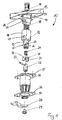
- einen Sicherheitsverschluss in einer Perspektivansicht seiner auseinandergezogen dargestellten Einzelteile,
- Fig. 2
- den Sicherheitsverschluss gemäß
Fig. 1 im Zustand einer Teilmontage seiner Einzelteile, - Fig. 3
- den Sicherheitsverschluss gemäß
Figuren 1 und2 in fertig montiertem Zustand.
- Fig. 1
- a safety lock in a perspective view of its exploded parts,
- Fig. 2
- the safety lock according to
Fig. 1 in a state of partial assembly of its parts, - Fig. 3
- the safety lock according to
FIGS. 1 and2 in ready assembled condition.
Wie sich aus
Die Drehspannhülse 12 weist einen ersten Lagerbereich 14 zur Lagerung und Führung des als T-Griff ausgebildeten Betätigungsgriffes 15 auf. Der Betätigungsgriff 15 steht mit einem Wellenansatz 16 in Richtung der Drehspannhülse 12 vor und greift in den ersten Lagerbereich 14 der Drehspannhülse derart ein, daß der Wellenansatz 16 in dem ersten Lagerbereich 14 sowohl drehbar als auch axial verschiebbar geführt ist. Zur Abdichtung des Betätigungsgriffes 15 gegen das die Drehspannhülse 12 aufnehmende Verschlussgehäuse 11 ist eine Dichtung 17 vorgesehen. In dem ersten Lagerbereich 14 ist eine Druckfeder 18 angeordnet, die sich im Tiefsten des ersten Lagerbereichs 14 abstützt und den Wellenansatz 16 des Betätigungsgriffes 15 nach Außen von dem Verschlussgehäuse weg in eine Betätigungsstellung vorspannt. In dem Wellenansatz 16 des Betätigungsgriffes 15 ist ein Zylinderschloss 19 als Schließorgan angeordnet, welches einen quer zur Achsrichtung des Wellenansatz 16 darin beweglichen Raststift 20 gegen die Wirkung einer nicht weiter dargestellten (inneren) Feder steuert. Der erste Lagerbereich 14 der Drehspannhülse 12 weist in seiner den Wellenansatz 16 des Betätigungsgriffes 15 umschließenden Wandung eine Ausnehmung 21 zur Aufnahme des Raststiftes 20 auf. Wie in der Darstellung der
Hinsichtlich des ersten Funktionsaspektes des Sicherheitsverschlusses 10 ist aus der vorstehenden Beschreibung einsehbar, daß der Betätigungsgriff 15 in die Drehspannhülse 12 gegen die Wirkung der Feder 18 eindrückbar ist, bis der federbelastete Raststift 20 in die Ausnehmung 21 der Drehspannhülse 12 eingreift. In dieser Raststellung ist dafür Sorge getragen, daß der Betätigungsgriff 15 mit einer an seiner Unterseite ausgebildeten Ausnehmung 37 den Flansch 35 des an der Tür oder Klappe festgelegten Verschlussgehäuses 11 formschlüssig übergreift, so daß in dieser Raststellung eine Betätigung des Betätigungsgriffes ausgeschlossen ist. Die Steuerung der Bewegung des Raststiftes 20 über das in dem Wellenansatz 16 untergebrachte Zylinderschloss 19 ist dabei so eingestellt, daß die Raststellung nur bei in der Schließstellung befindlichem Schlüssel des Zylinderschlosses 19 eingenommen wird. Wird das Zylinderschloss mit dem zugehörigen Schlüssel in die Öffnungsstellung gedreht, so steuert das Zylinderschloss 19 den Raststift 20 so, daß der Raststift 20 aus der Ausnehmung 21 der Drehspannhülse 12 freikommt, so daß die in der Raststellung gespannte Druckfeder 18 den Betätigungsgriff 15 in seine Betätigungsstellung herausdrückt, in welchem nun ein Abstand zwischen den Betätigungsgriff 15 und dem Flansch 35 des Verschlussgehäuses 11 gegeben ist; in dieser Stellung kann über den Betätigungsgriff 15 eine Betätigung des Sicherheitsverschlusses erfolgen.With regard to the first functional aspect of the
Im Hinblick auf die Ausbildung der Drehspannfunktion des Sicherheitsverschlusses 10 weist die Drehspannhülse 12 einen zweiten Lagerbereich 13 auf, in welchem eine Schließwelle 22 des Verschlusses sowohl drehbar als auch axial verschiebbar angeordnet ist. Die Schließwelle 22 trägt in formschlüssiger Verbindung mit ihr eine Schließzunge 28, die bei Anordnung eines Sicherungsringes 30 über eine axial in die Schließwelle 22 hineindrehbare Schraube 29 an der Schließwelle 22 festlegbar ist, und zwar aufgrund der Vierkantverbindung in einer drehfesten Verbindung miteinander.With regard to the formation of the rotational clamping function of the
Zur Steuerung der Schließwelle 22 bei ihrer Drehbewegung und Axialverschiebung in dem zweiten Lagerbereich 13 ist die Schließwelle mit einem sie quer durchsetzenden Stift 23 versehen, der in einer beidseitig an dem Lagerbereich 13 ausgebildeten Kulissenführung 25 geführt ist. Die Kulissenführung 25 besteht aus einem sich schraubenartig über die Längserstreckung des zweiten Lagerbereichs 13 der Drehspannhülse verlaufenden Schlitz 26, an dessen (oberem), dem zweiten Lagerbereich 13 zugewandten Ende ein in Umfangsrichtung ausgebildeter Halteabschnitt 23 anschließt. Weiterhin ist ein den zweiten Lagerbereich 13 außen umgreifender und die Kulissenführung 25 mit darin laufenden Enden des Stiftes 23 übergreifender Schaltring 31 angeordnet, der seinerseits in einer in der Zeichnung nicht dargestellten Weise drehfest im Inneren des Verschlussgehäuses 11 festgelegt ist. Der Schaltring 31 weist im Bereich der Kulissenführung 25 jeweils eine fensterartige Ausnehmung 33 auf, mittels derer Steuerkanten 32 zur Steuerung der in der Kulissenführung 25 laufenden Enden des Stiftes 23 gebildet sind.For controlling the
Die diesbezügliche Zusammenmontage von Drehspannhülse, Schließwelle und Schaltring ist
Wie im Stand der Technik hinsichtlich der Funktion eines Drehspannverschlusses an sich bekannt, erfolgt bei Drehung der Drehspannhülse 12 in dem Verschlussgehäuse 11 aufgrund der in dem zweiten Lagerbereich 13 der Drehspannhülse 12 angeordneten Schließwelle 22 eine Drehung der Schließzunge 28 in deren Schließstellung, in welcher die Schließzunge 28 einen zugeordneten fahrzeugfesten Rahmenteil hintergreift. Dabei liegt die Schließzunge 28 noch nicht gegen den Rahmen an, sondern wird erst durch eine Weiterdrehung der Drehspannhülse 12 über den Betätigungsgriff 15 aufgrund einer dadurch bewirkten Axialverschiebung in eine gespannte Anlage an dem Rahmenteil gebracht. Bei der diesbezüglichen Weiterdrehung nämlich wird der Stift 23 der Schließwelle 22 an den Steuerkanten 32 des Schaltringes 31 festgelegt, so daß sich bei einer weiteren Relativdrehung der Drehspannhülse 12 gegenüber der nunmehr festgelegten Schließwelle 22 die Schließwelle aufgrund von deren Führung über die Enden des Stiftes 23 in dem Gewindeschlitz 26 der Kulissenführung 25 axial verschoben, bis die Enden des Stiftes 23 in dem jeweiligen Halteabschnitt 27 der Kulissenführung 25 zu liegen kommen, so daß damit die Schließstellung der Schließzunge 28 erreicht ist, in welcher die Schließzunge 28 gegen das betreffende Rahmenteil vorgespannt ist. Bei der axialen Verschiebung wird die Feder 24 gespannt, die somit die Schließwelle 22 in deren Stellung mit von dem Rahmenteil abgehobener Schließzunge 28 vorspannt. Soll nun der Verschluss 10 wieder geöffnet werden, so führt eine Drehung des Betätigungsgriffes 15 mit Drehspannhülse 12 in die Öffnungsrichtung aufgrund des Anschlages der Enden des Stiftes 23 gegen die zugeordneten Steuerkanten 32 des drehfest mit dem Verschlussgehäuse 11 verbundenen Schaltringes 31 dazu, daß die Stiftenden aus dem Halteabschnitt 27 der Kulissenführung 25 heraustreten, so daß die gespannte Feder 24 die Schließwelle 22 nun bei gleichzeitiger Rückdrehung axial verschiebt und somit in eine Stellung verbringt, in welcher die von der Schließwelle 22 getragene Schließzunge 28 von dem zugeordneten Rahmenteil abgehoben ist. Durch eine weitere Drehung der Drehspannhülse 12 über den drehfest damit verbundenen Betätigungsgriff 15 wird die Schließzunge 28 in deren Öffnungsstellung verbracht.As known in the art with respect to the function of a rotary clamping closure per se, takes place during rotation of the
Die in der vorstehenden Beschreibung, den Patentansprüchen, der Zusammenfassung und der Zeichnung offenbarten Merkmale des Gegenstandes dieser Unterlagen können einzeln als auch in beliebigen Kombinationen untereinander für die Verwirklichung der Erfindung in ihren verschiedenen Ausführungsformen wesentlich sein.The features disclosed in the foregoing description, the claims, the abstract and the drawings of the subject matter of these documents may be essential individually as well as in any combination with each other for the realization of the invention in its various embodiments.
Claims (12)
- Safety closure for doors or flaps arranged on a vehicle, in particular motorhome or caravan, comprising a closure housing (11) which is fitted on a part mounted on the vehicle and in which a locking shaft (22), the free end of which bears a locking tongue (28), is arranged in a manner such that it can be rotated by means of an operating handle (15) between a locking position and an open position for the door or flap, in which the locking shaft (22) is part of a rotary clamping closure, wherein the locking shaft (22) is displaced by an axial distance during the rotation thereof between an open position and a locking position, and in which the operating handle (15) which is lockable via a cylinder lock (19) is arranged in a movable manner relative to the locking shaft (22) and is arranged in an axially displaceable manner between a latching position fixed in a form-fitting manner on a housing part (25) fitted on the outside of the door or flap and an operating position protruding from the housing part (35).
- Safety closure according to Claim 1, in which a rotary clamping sleeve (12) with a second bearing region (13) having a slotted guide (25) for the locking shaft (22), which is arranged rotatably therein and displaceably axially relative thereto, as a support for the closure tongue (28), is mounted rotatably in the closure housing (11), wherein the operating handle (15) is guided in the rotary clamping sleeve (12), by means of a shaft attachment (16) reaching into a first bearing region (14) of the rotary clamping sleeve (12), in a manner such that said operating handle is displaceable axially between the latching position thereof and the operating position thereof counter to the force of a spring (18) prestressing the operating handle (15) into the operating position thereof, and is coupled in a rotationally fixed manner to the rotary clamping sleeve (12).
- Safety closure according to Claim 1 or 2, in which a key-operated locking cylinder (19) is arranged in the shaft attachment (16) of the operating handle (15), said locking cylinder controlling a latching pin (20), which is movable transversely with respect to the shaft attachment, between an engagement position with the rotary clamping sleeve (12) and a sliding position.
- Safety closure according to Claim 3, in which the latching pin (20) is spring-loaded into the engagement position thereof with the rotary clamping sleeve (12).
- Safety closure according to one of Claims 1 to 4, in which a recess (21) for receiving the latching pin (20) in the engagement position thereof is arranged in the wall of the first bearing region (14) of the rotary clamping sleeve (12), which wall surrounds the shaft attachment (16) of the operating handle (15).
- Safety closure according to one of Claims 1 to 5, in which, in order to form the rotationally fixed connection, the shaft attachment (16) of the operating handle (15) is guided via a cam which protrudes radially from the said shaft extension and reaches through the wall of the first bearing region (14) of the rotary clamping sleeve (12) in a longitudinal slot formed therein, wherein the longitudinal slot ensures the axial displacement of the operating handle (15) relative to the rotary clamping sleeve (12).
- Safety closure according to one of Claims 1 to 6, in which the locking shaft (22) is guided rotatably and axially displaceably in the rotary clamping sleeve (12) in the second bearing region (13) of the rotary clamping sleeve (12) counter to the action of a spring (24), which prestresses the locking shaft (22) into the position thereof raised from the frame, by means of a pin (23) which reaches through the locking shaft (22) and is guided in the slotted guide (25) of the second bearing region (13) of the rotary clamping sleeve (12).
- Safety closure according to one of Claims 1 to 7, in which a switching ring (31) which engages over the slotted guide (25) and is intended for the pin (28) of the locking shaft (22) is arranged between the rotary clamping sleeve (12) and the inside of the closure housing (11) and is secured in a rotationally fixed manner on the inside of the closure housing (11).
- Safety closure according to Claim 8, in which the switching ring (31) has window-like recesses (33) which engage over the slotted guide (25) and are intended, with the incorporation of the stop edges (32) thereof, which are raised from the frame and are used in a position bearing against the frame, for forming the control of the pin (23) and therefore of the locking shaft (22) between the locking position and open position thereof.
- Safety closure according to one of Claims 1 to 9, in which the operating handle (15) is designed as a T handle.
- Safety closure according to Claim 10, characterized in that the lower side of the T handle (15) has a cutout (37) which, in the latching position of the T handle (15), engages in a form-fitting manner over a flange (35) of the closure housing (11), which flange rests on the outside of the door or flap.
- Safety closure according to Claim 10, characterized in that the closure housing (11) has a trough which rests on the outside of the door or flap and receives the operating handle (15) in a form-fitting manner therein in the latching position of said operating handle.
Applications Claiming Priority (2)
| Application Number | Priority Date | Filing Date | Title |
|---|---|---|---|
| DE202007013514U DE202007013514U1 (en) | 2007-09-27 | 2007-09-27 | Rotary clamping lock with operating handle safety |
| PCT/EP2008/007254 WO2009043420A1 (en) | 2007-09-27 | 2008-09-05 | Three-phase voltage closure with operating handle lock |
Publications (2)
| Publication Number | Publication Date |
|---|---|
| EP2106488A1 EP2106488A1 (en) | 2009-10-07 |
| EP2106488B1 true EP2106488B1 (en) | 2010-08-25 |
Family
ID=38806479
Family Applications (1)
| Application Number | Title | Priority Date | Filing Date |
|---|---|---|---|
| EP08801849A Active EP2106488B1 (en) | 2007-09-27 | 2008-09-05 | Three-phase voltage closure with operating handle lock |
Country Status (4)
| Country | Link |
|---|---|
| EP (1) | EP2106488B1 (en) |
| AT (1) | ATE479002T1 (en) |
| DE (2) | DE202007013514U1 (en) |
| WO (1) | WO2009043420A1 (en) |
Families Citing this family (13)
| Publication number | Priority date | Publication date | Assignee | Title |
|---|---|---|---|---|
| FR2944545B1 (en) * | 2009-04-20 | 2012-03-09 | Reel | DEVICE FOR ENABLING LOCK / UNLOCKING OF AN ELEMENT ON AND OUTSIDE A STRUCTURE. |
| FR2954591B1 (en) * | 2009-12-21 | 2012-01-13 | Renault Sa | TOOL FOR ASSEMBLING / DISASSEMBLING A BATTERY OF A MOTOR VEHICLE |
| GB2485190B (en) | 2010-11-04 | 2016-06-01 | Euro-Locks S A | Pull-up latch mechanism |
| DE102011116067A1 (en) * | 2011-07-22 | 2013-01-24 | Kiekert Ag | Tank flap lock with reduced number of components |
| DE202014100045U1 (en) | 2014-01-07 | 2014-04-28 | Emka Beschlagteile Gmbh & Co. Kg | Safety closure with a turnbuckle closure |
| IT201600076562A1 (en) * | 2016-09-02 | 2018-03-02 | Cev Lab S R L Con Unico Socio | LOCKING DEVICE |
| EP3473790B1 (en) | 2017-10-17 | 2021-05-19 | FAP S.r.l. | Rotatable closing device for doors and hatches provided with offset handle and latch |
| GB2580350A (en) * | 2019-01-03 | 2020-07-22 | Aanco Uk Ltd | Handle assembly |
| DE102019129440A1 (en) * | 2019-10-31 | 2021-05-06 | Emka Beschlagteile Gmbh & Co. Kg | Quarter turn for locking a door |
| CN111173367A (en) * | 2020-01-21 | 2020-05-19 | 江苏三乔智能科技有限公司 | Door and window lock with hidden handle |
| CN115038850A (en) * | 2020-01-31 | 2022-09-09 | 索斯科公司 | Modular latch system |
| CN111719951B (en) * | 2020-05-29 | 2024-01-05 | 宁波生久科技有限公司 | Pin tumbler lock core handle panel lock |
| US11584528B2 (en) | 2020-09-03 | 2023-02-21 | B/E Aerospace, Inc. | Aircraft trolley retention device |
Family Cites Families (5)
| Publication number | Priority date | Publication date | Assignee | Title |
|---|---|---|---|---|
| US5265454A (en) * | 1991-11-19 | 1993-11-30 | Eastern Company | Combined lock and latch |
| US5165738A (en) * | 1991-12-17 | 1992-11-24 | Southco | Latch assembly |
| US5961162A (en) * | 1997-09-17 | 1999-10-05 | Southco, Inc. | Apparatus and method for mounting latching devices |
| EP0905340A1 (en) * | 1997-09-24 | 1999-03-31 | Dzus Fastener Europe Limited | Double action pawl latch |
| DE29820711U1 (en) * | 1998-11-19 | 2000-03-30 | Ramsauer Dieter | Turn lock with pulling device |
-
2007
- 2007-09-27 DE DE202007013514U patent/DE202007013514U1/en not_active Expired - Lifetime
-
2008
- 2008-09-05 EP EP08801849A patent/EP2106488B1/en active Active
- 2008-09-05 DE DE502008001202T patent/DE502008001202D1/en active Active
- 2008-09-05 WO PCT/EP2008/007254 patent/WO2009043420A1/en active Application Filing
- 2008-09-05 AT AT08801849T patent/ATE479002T1/en active
Also Published As
| Publication number | Publication date |
|---|---|
| DE502008001202D1 (en) | 2010-10-07 |
| EP2106488A1 (en) | 2009-10-07 |
| DE202007013514U1 (en) | 2007-12-06 |
| WO2009043420A1 (en) | 2009-04-09 |
| ATE479002T1 (en) | 2010-09-15 |
Similar Documents
| Publication | Publication Date | Title |
|---|---|---|
| EP2106488B1 (en) | Three-phase voltage closure with operating handle lock | |
| EP2261066B1 (en) | Trailer device | |
| WO2012034860A1 (en) | Rotary clamping closure with perceptibility of the closure position | |
| EP1035286A2 (en) | Safety locking, particularly for doors in built-in furniture for caravans | |
| EP1712716A2 (en) | Vibration-proof rotary fastener | |
| EP3870786B1 (en) | Lock for a motor vehicle, in particular an electrically actuatable motor vehicle lock | |
| EP2877657B1 (en) | Tumbler for an access protection device with an emergency release | |
| EP3612697B1 (en) | Lock for a motor vehicle | |
| DE102007061055A1 (en) | door assembly | |
| DE102013010835A1 (en) | Retractable push-button element for sealable or lockable piece of furniture such as cabinet door, has disengageable blocking device e.g. link guide, and square arranged with lock housing that is arranged in geared connection with square | |
| DE3827418A1 (en) | LOCKING CYLINDER | |
| EP3784855B1 (en) | Motor vehicle lock | |
| DE102007011554B4 (en) | Coupling unit for electronic locking systems | |
| EP2699448A1 (en) | Locking device for a foldable backrest of a seat | |
| EP2317037A2 (en) | Swivel lever lock with split actuation shaft | |
| EP2733286B1 (en) | Pivoting lever closure with low installation depth | |
| DE19743962B4 (en) | Hinge for pivoting adjustment of a motor vehicle door | |
| WO2017103175A1 (en) | Closing device for a door, door assembly | |
| WO2008113467A1 (en) | Compression swivel lever closure | |
| EP2626490B1 (en) | Lock assembly | |
| DE102018131779A1 (en) | Locking device | |
| EP3517715A1 (en) | Holder with auxiliary unlock | |
| DE10331622A1 (en) | closure device | |
| DE102018133301A1 (en) | Lock for a motor vehicle | |
| DE102011110636B4 (en) | Locking device and portable container equipped therewith |
Legal Events
| Date | Code | Title | Description |
|---|---|---|---|
| PUAI | Public reference made under article 153(3) epc to a published international application that has entered the european phase |
Free format text: ORIGINAL CODE: 0009012 |
|
| 17P | Request for examination filed |
Effective date: 20090810 |
|
| AK | Designated contracting states |
Kind code of ref document: A1 Designated state(s): AT BE BG CH CY CZ DE DK EE ES FI FR GB GR HR HU IE IS IT LI LT LU LV MC MT NL NO PL PT RO SE SI SK TR |
|
| GRAP | Despatch of communication of intention to grant a patent |
Free format text: ORIGINAL CODE: EPIDOSNIGR1 |
|
| DAX | Request for extension of the european patent (deleted) | ||
| GRAS | Grant fee paid |
Free format text: ORIGINAL CODE: EPIDOSNIGR3 |
|
| GRAA | (expected) grant |
Free format text: ORIGINAL CODE: 0009210 |
|
| STAA | Information on the status of an ep patent application or granted ep patent |
Free format text: STATUS: THE PATENT HAS BEEN GRANTED |
|
| AK | Designated contracting states |
Kind code of ref document: B1 Designated state(s): AT BE BG CH CY CZ DE DK EE ES FI FR GB GR HR HU IE IS IT LI LT LU LV MC MT NL NO PL PT RO SE SI SK TR |
|
| REG | Reference to a national code |
Ref country code: GB Ref legal event code: FG4D Free format text: NOT ENGLISH |
|
| REG | Reference to a national code |
Ref country code: CH Ref legal event code: EP |
|
| REG | Reference to a national code |
Ref country code: IE Ref legal event code: FG4D Free format text: LANGUAGE OF EP DOCUMENT: GERMAN |
|
| REF | Corresponds to: |
Ref document number: 502008001202 Country of ref document: DE Date of ref document: 20101007 Kind code of ref document: P |
|
| REG | Reference to a national code |
Ref country code: NL Ref legal event code: VDEP Effective date: 20100825 |
|
| LTIE | Lt: invalidation of european patent or patent extension |
Effective date: 20100825 |
|
| PG25 | Lapsed in a contracting state [announced via postgrant information from national office to epo] |
Ref country code: LT Free format text: LAPSE BECAUSE OF FAILURE TO SUBMIT A TRANSLATION OF THE DESCRIPTION OR TO PAY THE FEE WITHIN THE PRESCRIBED TIME-LIMIT Effective date: 20100825 Ref country code: NO Free format text: LAPSE BECAUSE OF FAILURE TO SUBMIT A TRANSLATION OF THE DESCRIPTION OR TO PAY THE FEE WITHIN THE PRESCRIBED TIME-LIMIT Effective date: 20101125 Ref country code: FI Free format text: LAPSE BECAUSE OF FAILURE TO SUBMIT A TRANSLATION OF THE DESCRIPTION OR TO PAY THE FEE WITHIN THE PRESCRIBED TIME-LIMIT Effective date: 20100825 |
|
| PG25 | Lapsed in a contracting state [announced via postgrant information from national office to epo] |
Ref country code: HR Free format text: LAPSE BECAUSE OF FAILURE TO SUBMIT A TRANSLATION OF THE DESCRIPTION OR TO PAY THE FEE WITHIN THE PRESCRIBED TIME-LIMIT Effective date: 20100825 Ref country code: CY Free format text: LAPSE BECAUSE OF FAILURE TO SUBMIT A TRANSLATION OF THE DESCRIPTION OR TO PAY THE FEE WITHIN THE PRESCRIBED TIME-LIMIT Effective date: 20100825 Ref country code: SI Free format text: LAPSE BECAUSE OF FAILURE TO SUBMIT A TRANSLATION OF THE DESCRIPTION OR TO PAY THE FEE WITHIN THE PRESCRIBED TIME-LIMIT Effective date: 20100825 Ref country code: PL Free format text: LAPSE BECAUSE OF FAILURE TO SUBMIT A TRANSLATION OF THE DESCRIPTION OR TO PAY THE FEE WITHIN THE PRESCRIBED TIME-LIMIT Effective date: 20100825 Ref country code: IS Free format text: LAPSE BECAUSE OF FAILURE TO SUBMIT A TRANSLATION OF THE DESCRIPTION OR TO PAY THE FEE WITHIN THE PRESCRIBED TIME-LIMIT Effective date: 20101225 Ref country code: BG Free format text: LAPSE BECAUSE OF FAILURE TO SUBMIT A TRANSLATION OF THE DESCRIPTION OR TO PAY THE FEE WITHIN THE PRESCRIBED TIME-LIMIT Effective date: 20101125 |
|
| REG | Reference to a national code |
Ref country code: IE Ref legal event code: FD4D |
|
| BERE | Be: lapsed |
Owner name: OBERHOLZ-DUSSER, ISABEL Effective date: 20100930 |
|
| PG25 | Lapsed in a contracting state [announced via postgrant information from national office to epo] |
Ref country code: NL Free format text: LAPSE BECAUSE OF FAILURE TO SUBMIT A TRANSLATION OF THE DESCRIPTION OR TO PAY THE FEE WITHIN THE PRESCRIBED TIME-LIMIT Effective date: 20100825 Ref country code: SE Free format text: LAPSE BECAUSE OF FAILURE TO SUBMIT A TRANSLATION OF THE DESCRIPTION OR TO PAY THE FEE WITHIN THE PRESCRIBED TIME-LIMIT Effective date: 20100825 Ref country code: GR Free format text: LAPSE BECAUSE OF FAILURE TO SUBMIT A TRANSLATION OF THE DESCRIPTION OR TO PAY THE FEE WITHIN THE PRESCRIBED TIME-LIMIT Effective date: 20101126 Ref country code: LV Free format text: LAPSE BECAUSE OF FAILURE TO SUBMIT A TRANSLATION OF THE DESCRIPTION OR TO PAY THE FEE WITHIN THE PRESCRIBED TIME-LIMIT Effective date: 20100825 |
|
| PG25 | Lapsed in a contracting state [announced via postgrant information from national office to epo] |
Ref country code: DK Free format text: LAPSE BECAUSE OF FAILURE TO SUBMIT A TRANSLATION OF THE DESCRIPTION OR TO PAY THE FEE WITHIN THE PRESCRIBED TIME-LIMIT Effective date: 20100825 Ref country code: MC Free format text: LAPSE BECAUSE OF NON-PAYMENT OF DUE FEES Effective date: 20100930 Ref country code: IE Free format text: LAPSE BECAUSE OF FAILURE TO SUBMIT A TRANSLATION OF THE DESCRIPTION OR TO PAY THE FEE WITHIN THE PRESCRIBED TIME-LIMIT Effective date: 20100825 |
|
| PLBI | Opposition filed |
Free format text: ORIGINAL CODE: 0009260 |
|
| PG25 | Lapsed in a contracting state [announced via postgrant information from national office to epo] |
Ref country code: RO Free format text: LAPSE BECAUSE OF FAILURE TO SUBMIT A TRANSLATION OF THE DESCRIPTION OR TO PAY THE FEE WITHIN THE PRESCRIBED TIME-LIMIT Effective date: 20100825 Ref country code: EE Free format text: LAPSE BECAUSE OF FAILURE TO SUBMIT A TRANSLATION OF THE DESCRIPTION OR TO PAY THE FEE WITHIN THE PRESCRIBED TIME-LIMIT Effective date: 20100825 Ref country code: SK Free format text: LAPSE BECAUSE OF FAILURE TO SUBMIT A TRANSLATION OF THE DESCRIPTION OR TO PAY THE FEE WITHIN THE PRESCRIBED TIME-LIMIT Effective date: 20100825 Ref country code: IT Free format text: LAPSE BECAUSE OF FAILURE TO SUBMIT A TRANSLATION OF THE DESCRIPTION OR TO PAY THE FEE WITHIN THE PRESCRIBED TIME-LIMIT Effective date: 20100825 Ref country code: CZ Free format text: LAPSE BECAUSE OF FAILURE TO SUBMIT A TRANSLATION OF THE DESCRIPTION OR TO PAY THE FEE WITHIN THE PRESCRIBED TIME-LIMIT Effective date: 20100825 |
|
| 26 | Opposition filed |
Opponent name: RAMSAUER, DIETER Effective date: 20110510 |
|
| PG25 | Lapsed in a contracting state [announced via postgrant information from national office to epo] |
Ref country code: ES Free format text: LAPSE BECAUSE OF FAILURE TO SUBMIT A TRANSLATION OF THE DESCRIPTION OR TO PAY THE FEE WITHIN THE PRESCRIBED TIME-LIMIT Effective date: 20101206 |
|
| REG | Reference to a national code |
Ref country code: DE Ref legal event code: R026 Ref document number: 502008001202 Country of ref document: DE Effective date: 20110510 |
|
| PG25 | Lapsed in a contracting state [announced via postgrant information from national office to epo] |
Ref country code: BE Free format text: LAPSE BECAUSE OF NON-PAYMENT OF DUE FEES Effective date: 20100930 |
|
| PLBG | Opposition deemed not to have been filed |
Free format text: ORIGINAL CODE: 0009274 |
|
| 26D | Opposition deemed not to have been filed |
Opponent name: RAMSAUER, DIETER Effective date: 20110916 |
|
| PG25 | Lapsed in a contracting state [announced via postgrant information from national office to epo] |
Ref country code: MT Free format text: LAPSE BECAUSE OF FAILURE TO SUBMIT A TRANSLATION OF THE DESCRIPTION OR TO PAY THE FEE WITHIN THE PRESCRIBED TIME-LIMIT Effective date: 20100825 |
|
| PG25 | Lapsed in a contracting state [announced via postgrant information from national office to epo] |
Ref country code: HU Free format text: LAPSE BECAUSE OF FAILURE TO SUBMIT A TRANSLATION OF THE DESCRIPTION OR TO PAY THE FEE WITHIN THE PRESCRIBED TIME-LIMIT Effective date: 20110226 Ref country code: LU Free format text: LAPSE BECAUSE OF NON-PAYMENT OF DUE FEES Effective date: 20100905 |
|
| PG25 | Lapsed in a contracting state [announced via postgrant information from national office to epo] |
Ref country code: TR Free format text: LAPSE BECAUSE OF FAILURE TO SUBMIT A TRANSLATION OF THE DESCRIPTION OR TO PAY THE FEE WITHIN THE PRESCRIBED TIME-LIMIT Effective date: 20100825 |
|
| REG | Reference to a national code |
Ref country code: CH Ref legal event code: PL |
|
| PG25 | Lapsed in a contracting state [announced via postgrant information from national office to epo] |
Ref country code: PT Free format text: LAPSE BECAUSE OF NON-PAYMENT OF DUE FEES Effective date: 20100825 Ref country code: CH Free format text: LAPSE BECAUSE OF NON-PAYMENT OF DUE FEES Effective date: 20120930 Ref country code: LI Free format text: LAPSE BECAUSE OF NON-PAYMENT OF DUE FEES Effective date: 20120930 |
|
| REG | Reference to a national code |
Ref country code: AT Ref legal event code: MM01 Ref document number: 479002 Country of ref document: AT Kind code of ref document: T Effective date: 20130905 |
|
| PG25 | Lapsed in a contracting state [announced via postgrant information from national office to epo] |
Ref country code: AT Free format text: LAPSE BECAUSE OF NON-PAYMENT OF DUE FEES Effective date: 20130905 |
|
| REG | Reference to a national code |
Ref country code: FR Ref legal event code: PLFP Year of fee payment: 9 |
|
| REG | Reference to a national code |
Ref country code: FR Ref legal event code: PLFP Year of fee payment: 10 |
|
| REG | Reference to a national code |
Ref country code: FR Ref legal event code: PLFP Year of fee payment: 11 |
|
| PGFP | Annual fee paid to national office [announced via postgrant information from national office to epo] |
Ref country code: GB Payment date: 20230920 Year of fee payment: 16 |
|
| PGFP | Annual fee paid to national office [announced via postgrant information from national office to epo] |
Ref country code: FR Payment date: 20230928 Year of fee payment: 16 Ref country code: DE Payment date: 20230920 Year of fee payment: 16 |