EP2106355B1 - Structure de porte pour vehicule - Google Patents
Structure de porte pour vehicule Download PDFInfo
- Publication number
- EP2106355B1 EP2106355B1 EP08719280A EP08719280A EP2106355B1 EP 2106355 B1 EP2106355 B1 EP 2106355B1 EP 08719280 A EP08719280 A EP 08719280A EP 08719280 A EP08719280 A EP 08719280A EP 2106355 B1 EP2106355 B1 EP 2106355B1
- Authority
- EP
- European Patent Office
- Prior art keywords
- vehicle door
- impact beam
- vehicle
- wavy portion
- impact
- Prior art date
- Legal status (The legal status is an assumption and is not a legal conclusion. Google has not performed a legal analysis and makes no representation as to the accuracy of the status listed.)
- Not-in-force
Links
Images


Classifications
-
- B—PERFORMING OPERATIONS; TRANSPORTING
- B60—VEHICLES IN GENERAL
- B60J—WINDOWS, WINDSCREENS, NON-FIXED ROOFS, DOORS, OR SIMILAR DEVICES FOR VEHICLES; REMOVABLE EXTERNAL PROTECTIVE COVERINGS SPECIALLY ADAPTED FOR VEHICLES
- B60J5/00—Doors
- B60J5/04—Doors arranged at the vehicle sides
- B60J5/042—Reinforcement elements
- B60J5/0422—Elongated type elements, e.g. beams, cables, belts or wires
- B60J5/0423—Elongated type elements, e.g. beams, cables, belts or wires characterised by position in the lower door structure
- B60J5/0429—Elongated type elements, e.g. beams, cables, belts or wires characterised by position in the lower door structure the elements being arranged diagonally
-
- B—PERFORMING OPERATIONS; TRANSPORTING
- B60—VEHICLES IN GENERAL
- B60J—WINDOWS, WINDSCREENS, NON-FIXED ROOFS, DOORS, OR SIMILAR DEVICES FOR VEHICLES; REMOVABLE EXTERNAL PROTECTIVE COVERINGS SPECIALLY ADAPTED FOR VEHICLES
- B60J5/00—Doors
- B60J5/04—Doors arranged at the vehicle sides
- B60J5/042—Reinforcement elements
- B60J5/0422—Elongated type elements, e.g. beams, cables, belts or wires
- B60J5/0437—Elongated type elements, e.g. beams, cables, belts or wires characterised by the attachment means to the door, e.g. releasable attachment means
-
- B—PERFORMING OPERATIONS; TRANSPORTING
- B60—VEHICLES IN GENERAL
- B60J—WINDOWS, WINDSCREENS, NON-FIXED ROOFS, DOORS, OR SIMILAR DEVICES FOR VEHICLES; REMOVABLE EXTERNAL PROTECTIVE COVERINGS SPECIALLY ADAPTED FOR VEHICLES
- B60J5/00—Doors
- B60J5/04—Doors arranged at the vehicle sides
- B60J5/042—Reinforcement elements
- B60J5/0422—Elongated type elements, e.g. beams, cables, belts or wires
- B60J5/0438—Elongated type elements, e.g. beams, cables, belts or wires characterised by the type of elongated elements
- B60J5/0443—Beams
Definitions
- the invention relates to a vehicle door structure.
- a vehicle door is usually provided with an impact beam to protect occupants from an impact of a side collision.
- the impact beam extends along the longitudinal direction of a vehicle, and absorbs an impact load applied to a side portion of the vehicle.
- An example of the vehicle door provided with such an impact beam is described in Japanese Patent Application Publication No. 2003-211961 ( JP-A-2003-211961 ).
- the vehicle door is provided with a lateral beam, which extends along the width direction of the vehicle door (i.e. the longitudinal direction of the vehicle), and a branch beam.
- the lateral beam and the branch beam are fixed to fixing portions that are fixed to the main body of the vehicle door.
- the lateral beam and the branch beam are disposed at different positions in the height direction of the vehicle door. Therefore, the area in which the beams are present becomes wider in the height direction of the vehicle door. As a result, the protective area in the vehicle door, which is protected by the beams, is widened in the height direction of the vehicle door.
- the invention provides a vehicle door structure with which a protective area in a vehicle door is widened in the height direction of the vehicle door without increasing the number of vehicle door components and complexity in the structure of the vehicle door.
- An aspect of the invention relates to a vehicle door structure including an impact beam that is provided in a vehicle door and that absorbs an impact of a vehicle collision.
- the impact beam has a wavy portion that undulates in the height direction of the vehicle door.
- the impact beam may be disposed in such a manner that the center axis of the wavy portion extends along the longitudinal direction of the vehicle.
- the impact beam has the wavy portion described above, a protective area in the vehicle door, which is protected by the impact beam, is widened in the height direction of the vehicle door. Further, because the wavy portion is formed by, for example, bending the impact beam, neither the number of vehicle door components nor complexity in the structure of the vehicle door is increased. Accordingly, the protective area in the vehicle door is widened in the height direction of the vehicle door, without increasing the number of vehicle door components and complexity in the structure of the vehicle door.
- At least one end portion of the impact beam may be bent upward or downward with respect to the center axis of the wavy portion.
- At least one end portion of the impact beam is bent upward or downward with respect to the center axis of the wavy portion. Accordingly, even when a load produced at the time of a vehicle collision is applied to, for example, a top end of the wavy portion, the impact beam hardly rotates about the center axis of the wavy portion. As a result, the impact beam absorbs an impact of a vehicle collision more effectively.
- the protective area in the vehicle door is widened in the height direction of the vehicle door, without increasing the number of vehicle door components and complexity in the structure of the vehicle door.
- FIG. 1 is a front view of a vehicle door structure according to a first embodiment of the invention.
- FIG. 1 shows a left vehicle door 1 of a vehicle when viewed from the outside of the vehicle.
- the vehicle door 1 is shown with an outer panel removed.
- the vehicle door 1, shown in FIG..1 according to the first embodiment of the invention includes an inner panel 2 and an outer panel (not shown).
- An impact beam 3 is attached to the outer-side surface of the inner panel 2, and the outer panel covers the outer-side surface of the inner panel 2 to which the impact beam 3 is attached.
- the impact beam 3 is formed of a pipe member having a circular cross-section, and disposed along the longitudinal direction of the vehicle (i.e. the width direction of the vehicle door 1).
- the impact beam 3 is formed by processing a straight pipe member in such a manner that a wavy portion 11 is formed therein.
- the wavy portion 11 is formed by bending a portion of the pipe member up and down.
- the thus formed impact beam 3 is attached to the inner panel 2 in such a manner that the wavy portion 11 undulates in the height direction of the vehicle door 1 in a side view of the vehicle (i.e. in a front view of the vehicle door 1).
- a front-end portion 12 and a rear-end portion 13, which are contiguous with the wavy portion 11, are formed at respective end portions of the impact beam 3.
- a center axis of the wavy portion 11 extends along the longitudinal direction of the vehicle.
- the wavy portion 11 enables the impact beam 3 to protect a wider area in the inner panel 2 in the height direction of the vehicle door 1.
- the front-end portion 12 of the impact beam 3 is fixed by welding to a front bracket 4 disposed at the front-end portion of the inner panel 2.
- the rear-end portion 13 of the impact beam 3 is fixed by welding to a rear bracket 5 disposed at the rear-end portion of the inner panel 2.
- the impact beam 3 is attached to the inner panel 2 by the front bracket 4 and the rear bracket 5.
- the impact beam 3 provided in the vehicle door 1 has the wavy portion 11 that undulates in the height direction of the vehicle door 1.
- the wavy portion 11 provides the vehicle door 1 with a wider impact receiving surface that receives an impact of a collision between the vehicle door 1 (the side surface of the vehicle) and, for example, another vehicle.
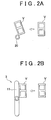
- FIG. 2A shows a manner in which a straight impact beam of the host vehicle contacts a bumper member of another vehicle when a side collision occurs.
- FIG. 2B shows a manner in which the impact beam of the host vehicle according to the first embodiment of the invention contacts a bumper member of another vehicle when a side collision occurs.
- FIG. 2A shows the case in which the other vehicle V collides with the vehicle door provided with the straight impact beam 20.
- the impact beam 3 according to the first embodiment has the wavy portion 11, and the impact beam 3 protects a wider area in the vehicle door 1 in the height direction of the vehicle door 1. Therefore, not only when the other vehicle V collides with the vehicle door 1 at a position near the center axis of the wavy portion 11, but also when the other vehicle V collides with the vehicle door 1 at a position higher than the center axis of the wavy portion 11 as shown in FIG. 2B , a reaction force by which the other vehicle V is pushed back is increased. Accordingly, the protective area in the vehicle door 1, which is protected by the impact beam 3, is widened in the height direction of the vehicle door 1.
- the protective area in the vehicle door 1 may also be widened in the height direction of the vehicle door 1 by, for example, providing a plurality of pipe members in the vehicle door 1.
- the impact beam 3 according to the first embodiment of the invention is formed by bending the straight pipe member. Therefore, the number of vehicle door components and the weight of the impact beam are both reduced, as compared with the configuration in which a plurality of pipe members are used. Accordingly, the protective area in the vehicle door is widened in the height direction of the vehicle door, without increasing the number of vehicle door components and complexity in the structure of the vehicle door.
- a vehicle door structure according to the second embodiment of the invention differs from the vehicle door structure according to the first embodiment of the invention in shape of the end portions of the impact beam.
- the other configurations are the same as those in the first embodiment of the invention.
- a vehicle door 10 according to the second embodiment is provided with the inner panel 2, and an impact beam 30 is attached to the inner panel 2.
- the impact beam 30 is formed of a pipe member, and disposed along the longitudinal direction of the vehicle (i.e. the width direction of the vehicle door).
- the impact beam 30 is formed by processing a straight pipe member in such a manner that a wavy portion 31 is formed therein.
- the wavy portion 31 is formed by bending a portion of the pipe member up and down.
- the thus formed impact beam 30 is attached to the inner panel 2 in such a manner that the wavy portion 31 undulates in the height direction of the vehicle door 10 in a side view of the vehicle (i.e. in a front view of the vehicle door 1).
- a front-end portion 32 and a rear-end portion 33, which are contiguous with the wavy portion 31, are formed at respective end portions of the impact beam 30.
- a center axis C of the wavy portion 31 extends along the longitudinal direction of the vehicle.
- the wavy portion 31 enables the impact beam 30 to protect a wider area in the inner panel 2 in the height direction of the vehicle door 10.
- the front-end portion 32 of the impact beam 30 is bent downward to form an angle ⁇ with the center axis C of the wavy portion 31.
- the rear-end portion 33 of the impact beam 30 is also bent downward to form the angle ⁇ with the center axis C of the wavy portion 31.
- the impact beam 30 having the wavy portion 31 and the bent end portions 32 and 33 is formed by bending a straight pipe member.
- the wavy portion 31, which widens the protective area in the vehicle door is in the height-direction of the vehicle door 1, is formed. Therefore, even when another vehicle collides with the vehicle door 1 at a position higher than the center axis of the wavy portion 31, a reaction force, by which the other vehicle is pushed back, is increased by the impact beam 30. Therefore, the protective area in the vehicle door 1 is widened in the height direction of the vehicle door 1. Further, the impact beam 30 according to the second embodiment is formed by bending a straight pipe member. Therefore, the number of vehicle door components and the weight of the impact beam are both reduced
- the vehicle door 10 according to the second embodiment is provided with the impact beam 30 of which the end portions 32 and 33 are bent downward. Due to this configuration, even when a load (shock) produced at the time of a vehicle collision acts on, for example, the top end of the wavy portion 31, the impact beam 30 hardly rotates about the center axis C of the wavy portion 31. As a result, the impact beam 30 absorbs the impact of a vehicle collision more effectively.
- the angle ⁇ formed between each of the bent end portions 32 and 33 of the impact beam 30 and the center axis C of the wavy portion 31 is not limited to a certain value, and may be, for example, 90 degrees, approximately 5 to 10 degrees, or a value larger than 90 degrees. It is preferable that the angle ⁇ be set to 90 degrees in order to effectively prevent the rotation of the impact beam 30 about the center axis C of the wavy portion 31. However, the angle ⁇ may be set to any appropriate value based on other factors, for example, based on how the impact beam 30 is arranged or the shape of the wavy portion 31.
- the impact beam is formed by bending one rod member (i.e. pipe member) in such a manner that the wavy portion is formed therein.
- the protective area in the vehicle door is widened in the height direction of the vehicle door, without increasing the number of vehicle door components and complexity in the structure of the vehicle door.
- both of the end portions 32 and 33 of the impact beam 30 are bent downward.
- both of the end portions 32 and 33 of the impact beam 30 may be bent upward.
- one of the end portions 32 and 33 may be bent upward, and the other of the end portions 32 and 33 may be bent downward.
Landscapes
- Engineering & Computer Science (AREA)
- Mechanical Engineering (AREA)
- Body Structure For Vehicles (AREA)
Claims (4)
- Structure de porte de véhicule comprenant une poutre d'impact (3, 30) qui est prévue dans une porte de véhicule et qui absorbe un impact d'une collision de véhicule, dans laquelle la poutre d'impact (3, 30) a une partie ondulée (11, 31), caractérisée en ce que la partie ondulée ondule dans une direction de hauteur de la porte de véhicule autour d'un axe de la poutre d'impact s'étendant entre ses extrémités.
- Structure de porte de véhicule selon la revendication 1, dans laquelle la poutre d'impact (3, 30) est disposée de sorte qu'un axe central de la partie ondulée s'étend le long d'une direction longitudinale du véhicule.
- Structure de porte de véhicule selon la revendication 1 ou 2, dans laquelle au moins une partie d'extrémité de la poutre d'impact (30) est courbée vers le haut ou vers le bas par rapport à l'axe central de la partie ondulée (31).
- Structure de porte de véhicule selon l'une quelconque des revendications 1 à 3, dans laquelle la poutre d'impact (30) est un élément de tuyau.
Applications Claiming Priority (2)
| Application Number | Priority Date | Filing Date | Title |
|---|---|---|---|
| JP2007023279A JP4265660B2 (ja) | 2007-02-01 | 2007-02-01 | 車両のドア構造 |
| PCT/IB2008/000572 WO2008093241A2 (fr) | 2007-02-01 | 2008-01-03 | Structure de porte pour véhicule |
Publications (2)
| Publication Number | Publication Date |
|---|---|
| EP2106355A2 EP2106355A2 (fr) | 2009-10-07 |
| EP2106355B1 true EP2106355B1 (fr) | 2012-02-22 |
Family
ID=39674572
Family Applications (1)
| Application Number | Title | Priority Date | Filing Date |
|---|---|---|---|
| EP08719280A Not-in-force EP2106355B1 (fr) | 2007-02-01 | 2008-01-03 | Structure de porte pour vehicule |
Country Status (6)
| Country | Link |
|---|---|
| US (1) | US8226154B2 (fr) |
| EP (1) | EP2106355B1 (fr) |
| JP (1) | JP4265660B2 (fr) |
| CN (1) | CN101600591B (fr) |
| AT (1) | ATE546308T1 (fr) |
| WO (1) | WO2008093241A2 (fr) |
Families Citing this family (8)
| Publication number | Priority date | Publication date | Assignee | Title |
|---|---|---|---|---|
| US20090025669A1 (en) * | 2007-07-25 | 2009-01-29 | Gerald Filipek | Heat source supplied glow plug/plasma torch and optional spark plasma torch for accomplishing more efficient piston combustion |
| JP5303211B2 (ja) * | 2008-04-08 | 2013-10-02 | 本田技研工業株式会社 | 車両用ドア構造体およびその製造方法 |
| JP6501508B2 (ja) * | 2014-12-08 | 2019-04-17 | キヤノン株式会社 | 画像形成装置 |
| US9487066B1 (en) | 2015-07-07 | 2016-11-08 | Toyota Motor Engineering & Manufacturing North America, Inc. | Deformable side impact bar |
| KR101896325B1 (ko) | 2016-11-15 | 2018-09-07 | 현대자동차 주식회사 | 차량용 cfrp 도어의 임팩트 빔 구조 |
| US10676055B2 (en) * | 2018-09-28 | 2020-06-09 | GM Global Technology Operations LLC | System for energy absorption and load transfer |
| JP6786650B2 (ja) * | 2019-03-15 | 2020-11-18 | キヤノン株式会社 | 除電ブラシ及び画像形成装置 |
| US11472270B2 (en) * | 2021-02-04 | 2022-10-18 | GM Global Technology Operations LLC | Impact absorbing reinforcement member |
Family Cites Families (32)
| Publication number | Priority date | Publication date | Assignee | Title |
|---|---|---|---|---|
| US1474949A (en) * | 1919-12-20 | 1923-11-20 | Sundh August | Flexible tubing |
| US3589687A (en) * | 1968-12-23 | 1971-06-29 | Monsanto Co | Packing element |
| GB1392710A (en) * | 1971-08-21 | 1975-04-30 | Gkn Sankey Ltd | Doors for vehicles |
| US4684166A (en) * | 1986-05-19 | 1987-08-04 | General Motors Corporation | Vehicle door impact beam and stabilizing assembly |
| JPS6361627A (ja) * | 1986-09-01 | 1988-03-17 | Nissan Motor Co Ltd | 自動車用ドアガ−ドバ− |
| JPH07115586B2 (ja) | 1986-10-27 | 1995-12-13 | 一仁 深澤 | 車体の衝撃吸収材 |
| DE4021235A1 (de) * | 1990-07-02 | 1992-01-16 | Mannesmann Ag | Tuerverstaerkerrohr |
| US5306068A (en) * | 1991-08-30 | 1994-04-26 | Toray Industries Inc. | Automobile door |
| SE502870C2 (sv) * | 1991-11-26 | 1996-02-05 | Volvo Ab | Föstärkningsbalk, exempelvis för fordonskarosseridetaljer |
| DE4244470A1 (de) | 1992-12-23 | 1994-06-30 | Porsche Ag | Tür, insbesondere für Kraftfahrzeuge |
| DE4308035C2 (de) * | 1993-03-13 | 1996-09-05 | Daimler Benz Ag | Karosserieschale für ein Kraftfahrzeugteil |
| US5536060A (en) * | 1995-02-17 | 1996-07-16 | General Motors Corporation | Reinforced vehicle door |
| US5580120A (en) * | 1995-02-23 | 1996-12-03 | Mascotech Tubular Products, Inc. | Vehicle door intrusion beam |
| DE29614488U1 (de) | 1996-08-21 | 1996-11-14 | Oehme Metallbearbeitung Kg | Fahrzeugtür mit Seitenaufprallschutz |
| DE19633637A1 (de) | 1996-08-21 | 1998-02-26 | Oehme Metallbearbeitung Kg | Fahrzeugtür mit Seitenaufprallschutz |
| AU5265098A (en) * | 1996-11-19 | 1998-06-10 | Alcoa Inc. | Safety door beam |
| DE19708215C2 (de) * | 1997-02-28 | 2001-06-28 | Audi Ag | Schweller eines Kraftfahrzeugs mit einer Verstärkungseinlage |
| DE19748970B4 (de) * | 1997-11-06 | 2005-12-08 | Ford Global Technologies, LLC (n.d.Ges.d. Staates Delaware), Dearborn | Integrale Türinnenverstärkung |
| US6135537A (en) * | 1997-12-22 | 2000-10-24 | Chrysler Corporation | Reinforced vehicle door assembly |
| EP1046772B1 (fr) * | 1999-04-22 | 2005-07-13 | Aisin Seiki Kabushiki Kaisha | Système de porte pour véhicule avec dispositif de serrure de porte et poignée extérieure |
| US6349521B1 (en) * | 1999-06-18 | 2002-02-26 | Shape Corporation | Vehicle bumper beam with non-uniform cross section |
| KR100405892B1 (ko) * | 2001-04-19 | 2003-11-14 | 기아자동차주식회사 | 측면 충돌에 대한 강성이 향상된 자동차의 플로어 패널조립체 |
| JP2003211961A (ja) | 2002-01-18 | 2003-07-30 | Aisin Takaoka Ltd | 車両用ドア及び車両用ドアビーム |
| US6779830B2 (en) * | 2002-04-09 | 2004-08-24 | Ford Global Technologies, Llc | Anti-intrusion beam for a vehicle door assembly |
| DE10223355B4 (de) * | 2002-05-25 | 2005-10-06 | Dr.Ing.H.C. F. Porsche Ag | Stoßauffangeinrichtung für Kraftfahrzeuge |
| JP4015896B2 (ja) | 2002-07-24 | 2007-11-28 | 株式会社神戸製鋼所 | 車体構造材および耐衝突補強材 |
| FR2846924B1 (fr) * | 2002-11-12 | 2006-12-15 | Arvinmeritor Light Vehicle Sys | Assemblage anti-intrusion |
| DE10341329B4 (de) * | 2003-09-08 | 2005-09-22 | Fraunhofer-Gesellschaft zur Förderung der angewandten Forschung e.V. | Vorrichtung und Verfahren zur Erhöhung des Insassenschutzes in einem Fahrzeug bei einem Seitenaufprall |
| JP4305149B2 (ja) | 2003-12-03 | 2009-07-29 | トヨタ自動車株式会社 | 車体側部構造 |
| WO2005058625A1 (fr) * | 2003-12-17 | 2005-06-30 | Sumitomo Metal Industries Ltd. | Tube metallique de renforcement pour le corps d'un vehicule et element de renforcement pour le corps d'un vehicule faisant intervenir ledit tube |
| DE102004020471B4 (de) * | 2004-04-26 | 2007-09-27 | Fraunhofer-Gesellschaft zur Förderung der angewandten Forschung e.V. | Vorrichtung zur Erhöhung des Insassenschutzes in einem Fahrzeug bei einem Seitenaufprall |
| US7819462B1 (en) * | 2009-04-21 | 2010-10-26 | Gm Global Technology Operations, Inc. | Anti-intrusion beam for vehicle door assembly |
-
2007
- 2007-02-01 JP JP2007023279A patent/JP4265660B2/ja not_active Expired - Fee Related
-
2008
- 2008-01-03 US US12/522,799 patent/US8226154B2/en not_active Expired - Fee Related
- 2008-01-03 CN CN2008800038482A patent/CN101600591B/zh not_active Expired - Fee Related
- 2008-01-03 EP EP08719280A patent/EP2106355B1/fr not_active Not-in-force
- 2008-01-03 WO PCT/IB2008/000572 patent/WO2008093241A2/fr active Application Filing
- 2008-01-03 AT AT08719280T patent/ATE546308T1/de active
Also Published As
| Publication number | Publication date |
|---|---|
| JP2008189056A (ja) | 2008-08-21 |
| JP4265660B2 (ja) | 2009-05-20 |
| EP2106355A2 (fr) | 2009-10-07 |
| US8226154B2 (en) | 2012-07-24 |
| CN101600591B (zh) | 2011-07-06 |
| WO2008093241A2 (fr) | 2008-08-07 |
| US20100013266A1 (en) | 2010-01-21 |
| CN101600591A (zh) | 2009-12-09 |
| ATE546308T1 (de) | 2012-03-15 |
| WO2008093241A3 (fr) | 2008-11-27 |
Similar Documents
| Publication | Publication Date | Title |
|---|---|---|
| EP2106355B1 (fr) | Structure de porte pour vehicule | |
| EP1609686B1 (fr) | Capot de véhicule | |
| CN106184382B (zh) | 车辆的连接结构 | |
| EP1972506B1 (fr) | Structure de montage de dispositif anti-encastrement sur un vehicule | |
| EP3461692B1 (fr) | Protecteur de capteur et véhicule en étant équipé | |
| EP2683566B1 (fr) | Dispositif de protection pour équipement électrique embarqué | |
| US20120119477A1 (en) | Combined structure of outer upper center pillar reinforcement and seat belt bracket | |
| JP2008049871A (ja) | 車両用ニープロテクタ構造 | |
| US9365240B2 (en) | Frontal collision impact absorbing device for vehicle | |
| JP2009001199A (ja) | バンパービーム構造 | |
| US7832764B2 (en) | Knee protector structure for vehicle | |
| US7472948B2 (en) | Vehicle body structure | |
| JP2005145224A (ja) | 車両用フード構造 | |
| JP2007223414A (ja) | 車両用フード構造 | |
| JP2009023638A (ja) | 車体前部構造 | |
| EP3386847B1 (fr) | Structure de soubassement de carrosserie de véhicule comprenant un élément de renforcement entre une poutre longitudinale et une partie fixe de face inférieure | |
| CN108177695B (zh) | 车辆侧部结构 | |
| JP4200941B2 (ja) | 車両用フード構造 | |
| JP2007320380A (ja) | 車両用ニープロテクタ構造 | |
| JP2005096604A (ja) | 車両用フード構造 | |
| JP2019137157A (ja) | 取付部材 | |
| JP7202240B2 (ja) | 車両前部構造 | |
| JP7338647B2 (ja) | アンダランプロテクタ固定構造 | |
| CN113613958B (zh) | 保险杠支承结构 | |
| US20030067190A1 (en) | Structural member for a motor vehicle |
Legal Events
| Date | Code | Title | Description |
|---|---|---|---|
| PUAI | Public reference made under article 153(3) epc to a published international application that has entered the european phase |
Free format text: ORIGINAL CODE: 0009012 |
|
| 17P | Request for examination filed |
Effective date: 20090709 |
|
| AK | Designated contracting states |
Kind code of ref document: A2 Designated state(s): AT BE BG CH CY CZ DE DK EE ES FI FR GB GR HR HU IE IS IT LI LT LU LV MC MT NL NO PL PT RO SE SI SK TR |
|
| DAX | Request for extension of the european patent (deleted) | ||
| GRAP | Despatch of communication of intention to grant a patent |
Free format text: ORIGINAL CODE: EPIDOSNIGR1 |
|
| GRAS | Grant fee paid |
Free format text: ORIGINAL CODE: EPIDOSNIGR3 |
|
| GRAA | (expected) grant |
Free format text: ORIGINAL CODE: 0009210 |
|
| AK | Designated contracting states |
Kind code of ref document: B1 Designated state(s): AT BE BG CH CY CZ DE DK EE ES FI FR GB GR HR HU IE IS IT LI LT LU LV MC MT NL NO PL PT RO SE SI SK TR |
|
| REG | Reference to a national code |
Ref country code: GB Ref legal event code: FG4D |
|
| REG | Reference to a national code |
Ref country code: CH Ref legal event code: EP |
|
| REG | Reference to a national code |
Ref country code: AT Ref legal event code: REF Ref document number: 546308 Country of ref document: AT Kind code of ref document: T Effective date: 20120315 |
|
| REG | Reference to a national code |
Ref country code: IE Ref legal event code: FG4D |
|
| REG | Reference to a national code |
Ref country code: DE Ref legal event code: R096 Ref document number: 602008013588 Country of ref document: DE Effective date: 20120426 |
|
| REG | Reference to a national code |
Ref country code: NL Ref legal event code: VDEP Effective date: 20120222 |
|
| LTIE | Lt: invalidation of european patent or patent extension |
Effective date: 20120222 |
|
| PG25 | Lapsed in a contracting state [announced via postgrant information from national office to epo] |
Ref country code: HR Free format text: LAPSE BECAUSE OF FAILURE TO SUBMIT A TRANSLATION OF THE DESCRIPTION OR TO PAY THE FEE WITHIN THE PRESCRIBED TIME-LIMIT Effective date: 20120222 Ref country code: NO Free format text: LAPSE BECAUSE OF FAILURE TO SUBMIT A TRANSLATION OF THE DESCRIPTION OR TO PAY THE FEE WITHIN THE PRESCRIBED TIME-LIMIT Effective date: 20120522 Ref country code: LT Free format text: LAPSE BECAUSE OF FAILURE TO SUBMIT A TRANSLATION OF THE DESCRIPTION OR TO PAY THE FEE WITHIN THE PRESCRIBED TIME-LIMIT Effective date: 20120222 Ref country code: NL Free format text: LAPSE BECAUSE OF FAILURE TO SUBMIT A TRANSLATION OF THE DESCRIPTION OR TO PAY THE FEE WITHIN THE PRESCRIBED TIME-LIMIT Effective date: 20120222 Ref country code: IS Free format text: LAPSE BECAUSE OF FAILURE TO SUBMIT A TRANSLATION OF THE DESCRIPTION OR TO PAY THE FEE WITHIN THE PRESCRIBED TIME-LIMIT Effective date: 20120622 |
|
| PG25 | Lapsed in a contracting state [announced via postgrant information from national office to epo] |
Ref country code: FI Free format text: LAPSE BECAUSE OF FAILURE TO SUBMIT A TRANSLATION OF THE DESCRIPTION OR TO PAY THE FEE WITHIN THE PRESCRIBED TIME-LIMIT Effective date: 20120222 Ref country code: PT Free format text: LAPSE BECAUSE OF FAILURE TO SUBMIT A TRANSLATION OF THE DESCRIPTION OR TO PAY THE FEE WITHIN THE PRESCRIBED TIME-LIMIT Effective date: 20120622 Ref country code: GR Free format text: LAPSE BECAUSE OF FAILURE TO SUBMIT A TRANSLATION OF THE DESCRIPTION OR TO PAY THE FEE WITHIN THE PRESCRIBED TIME-LIMIT Effective date: 20120523 Ref country code: BE Free format text: LAPSE BECAUSE OF FAILURE TO SUBMIT A TRANSLATION OF THE DESCRIPTION OR TO PAY THE FEE WITHIN THE PRESCRIBED TIME-LIMIT Effective date: 20120222 Ref country code: LV Free format text: LAPSE BECAUSE OF FAILURE TO SUBMIT A TRANSLATION OF THE DESCRIPTION OR TO PAY THE FEE WITHIN THE PRESCRIBED TIME-LIMIT Effective date: 20120222 |
|
| REG | Reference to a national code |
Ref country code: AT Ref legal event code: MK05 Ref document number: 546308 Country of ref document: AT Kind code of ref document: T Effective date: 20120222 |
|
| PG25 | Lapsed in a contracting state [announced via postgrant information from national office to epo] |
Ref country code: CY Free format text: LAPSE BECAUSE OF FAILURE TO SUBMIT A TRANSLATION OF THE DESCRIPTION OR TO PAY THE FEE WITHIN THE PRESCRIBED TIME-LIMIT Effective date: 20120222 |
|
| PG25 | Lapsed in a contracting state [announced via postgrant information from national office to epo] |
Ref country code: EE Free format text: LAPSE BECAUSE OF FAILURE TO SUBMIT A TRANSLATION OF THE DESCRIPTION OR TO PAY THE FEE WITHIN THE PRESCRIBED TIME-LIMIT Effective date: 20120222 Ref country code: CZ Free format text: LAPSE BECAUSE OF FAILURE TO SUBMIT A TRANSLATION OF THE DESCRIPTION OR TO PAY THE FEE WITHIN THE PRESCRIBED TIME-LIMIT Effective date: 20120222 Ref country code: RO Free format text: LAPSE BECAUSE OF FAILURE TO SUBMIT A TRANSLATION OF THE DESCRIPTION OR TO PAY THE FEE WITHIN THE PRESCRIBED TIME-LIMIT Effective date: 20120222 Ref country code: DK Free format text: LAPSE BECAUSE OF FAILURE TO SUBMIT A TRANSLATION OF THE DESCRIPTION OR TO PAY THE FEE WITHIN THE PRESCRIBED TIME-LIMIT Effective date: 20120222 Ref country code: SI Free format text: LAPSE BECAUSE OF FAILURE TO SUBMIT A TRANSLATION OF THE DESCRIPTION OR TO PAY THE FEE WITHIN THE PRESCRIBED TIME-LIMIT Effective date: 20120222 Ref country code: PL Free format text: LAPSE BECAUSE OF FAILURE TO SUBMIT A TRANSLATION OF THE DESCRIPTION OR TO PAY THE FEE WITHIN THE PRESCRIBED TIME-LIMIT Effective date: 20120222 Ref country code: SE Free format text: LAPSE BECAUSE OF FAILURE TO SUBMIT A TRANSLATION OF THE DESCRIPTION OR TO PAY THE FEE WITHIN THE PRESCRIBED TIME-LIMIT Effective date: 20120222 |
|
| REG | Reference to a national code |
Ref country code: GB Ref legal event code: 746 Effective date: 20121012 |
|
| PG25 | Lapsed in a contracting state [announced via postgrant information from national office to epo] |
Ref country code: SK Free format text: LAPSE BECAUSE OF FAILURE TO SUBMIT A TRANSLATION OF THE DESCRIPTION OR TO PAY THE FEE WITHIN THE PRESCRIBED TIME-LIMIT Effective date: 20120222 |
|
| REG | Reference to a national code |
Ref country code: DE Ref legal event code: R084 Ref document number: 602008013588 Country of ref document: DE Effective date: 20121015 |
|
| PLBE | No opposition filed within time limit |
Free format text: ORIGINAL CODE: 0009261 |
|
| STAA | Information on the status of an ep patent application or granted ep patent |
Free format text: STATUS: NO OPPOSITION FILED WITHIN TIME LIMIT |
|
| 26N | No opposition filed |
Effective date: 20121123 |
|
| PG25 | Lapsed in a contracting state [announced via postgrant information from national office to epo] |
Ref country code: AT Free format text: LAPSE BECAUSE OF FAILURE TO SUBMIT A TRANSLATION OF THE DESCRIPTION OR TO PAY THE FEE WITHIN THE PRESCRIBED TIME-LIMIT Effective date: 20120222 |
|
| REG | Reference to a national code |
Ref country code: DE Ref legal event code: R097 Ref document number: 602008013588 Country of ref document: DE Effective date: 20121123 |
|
| PG25 | Lapsed in a contracting state [announced via postgrant information from national office to epo] |
Ref country code: ES Free format text: LAPSE BECAUSE OF FAILURE TO SUBMIT A TRANSLATION OF THE DESCRIPTION OR TO PAY THE FEE WITHIN THE PRESCRIBED TIME-LIMIT Effective date: 20120602 |
|
| PG25 | Lapsed in a contracting state [announced via postgrant information from national office to epo] |
Ref country code: BG Free format text: LAPSE BECAUSE OF FAILURE TO SUBMIT A TRANSLATION OF THE DESCRIPTION OR TO PAY THE FEE WITHIN THE PRESCRIBED TIME-LIMIT Effective date: 20120522 |
|
| PG25 | Lapsed in a contracting state [announced via postgrant information from national office to epo] |
Ref country code: MC Free format text: LAPSE BECAUSE OF NON-PAYMENT OF DUE FEES Effective date: 20130131 |
|
| REG | Reference to a national code |
Ref country code: CH Ref legal event code: PL |
|
| REG | Reference to a national code |
Ref country code: IE Ref legal event code: MM4A |
|
| PG25 | Lapsed in a contracting state [announced via postgrant information from national office to epo] |
Ref country code: CH Free format text: LAPSE BECAUSE OF NON-PAYMENT OF DUE FEES Effective date: 20130131 Ref country code: LI Free format text: LAPSE BECAUSE OF NON-PAYMENT OF DUE FEES Effective date: 20130131 |
|
| PG25 | Lapsed in a contracting state [announced via postgrant information from national office to epo] |
Ref country code: IE Free format text: LAPSE BECAUSE OF NON-PAYMENT OF DUE FEES Effective date: 20130103 |
|
| PG25 | Lapsed in a contracting state [announced via postgrant information from national office to epo] |
Ref country code: MT Free format text: LAPSE BECAUSE OF FAILURE TO SUBMIT A TRANSLATION OF THE DESCRIPTION OR TO PAY THE FEE WITHIN THE PRESCRIBED TIME-LIMIT Effective date: 20120222 |
|
| REG | Reference to a national code |
Ref country code: FR Ref legal event code: PLFP Year of fee payment: 8 |
|
| PGFP | Annual fee paid to national office [announced via postgrant information from national office to epo] |
Ref country code: GB Payment date: 20141231 Year of fee payment: 8 |
|
| PGFP | Annual fee paid to national office [announced via postgrant information from national office to epo] |
Ref country code: DE Payment date: 20141231 Year of fee payment: 8 Ref country code: IT Payment date: 20150109 Year of fee payment: 8 |
|
| PGFP | Annual fee paid to national office [announced via postgrant information from national office to epo] |
Ref country code: FR Payment date: 20150108 Year of fee payment: 8 |
|
| PG25 | Lapsed in a contracting state [announced via postgrant information from national office to epo] |
Ref country code: TR Free format text: LAPSE BECAUSE OF FAILURE TO SUBMIT A TRANSLATION OF THE DESCRIPTION OR TO PAY THE FEE WITHIN THE PRESCRIBED TIME-LIMIT Effective date: 20120222 |
|
| PG25 | Lapsed in a contracting state [announced via postgrant information from national office to epo] |
Ref country code: LU Free format text: LAPSE BECAUSE OF NON-PAYMENT OF DUE FEES Effective date: 20130103 Ref country code: HU Free format text: LAPSE BECAUSE OF FAILURE TO SUBMIT A TRANSLATION OF THE DESCRIPTION OR TO PAY THE FEE WITHIN THE PRESCRIBED TIME-LIMIT; INVALID AB INITIO Effective date: 20080103 |
|
| REG | Reference to a national code |
Ref country code: DE Ref legal event code: R119 Ref document number: 602008013588 Country of ref document: DE |
|
| GBPC | Gb: european patent ceased through non-payment of renewal fee |
Effective date: 20160103 |
|
| REG | Reference to a national code |
Ref country code: FR Ref legal event code: ST Effective date: 20160930 |
|
| PG25 | Lapsed in a contracting state [announced via postgrant information from national office to epo] |
Ref country code: DE Free format text: LAPSE BECAUSE OF NON-PAYMENT OF DUE FEES Effective date: 20160802 Ref country code: GB Free format text: LAPSE BECAUSE OF NON-PAYMENT OF DUE FEES Effective date: 20160103 |
|
| PG25 | Lapsed in a contracting state [announced via postgrant information from national office to epo] |
Ref country code: FR Free format text: LAPSE BECAUSE OF NON-PAYMENT OF DUE FEES Effective date: 20160201 |
|
| PG25 | Lapsed in a contracting state [announced via postgrant information from national office to epo] |
Ref country code: IT Free format text: LAPSE BECAUSE OF NON-PAYMENT OF DUE FEES Effective date: 20160103 |