EP2106322B1 - Protective hood anti-rotation lock - Google Patents
Protective hood anti-rotation lock Download PDFInfo
- Publication number
- EP2106322B1 EP2106322B1 EP20070822423 EP07822423A EP2106322B1 EP 2106322 B1 EP2106322 B1 EP 2106322B1 EP 20070822423 EP20070822423 EP 20070822423 EP 07822423 A EP07822423 A EP 07822423A EP 2106322 B1 EP2106322 B1 EP 2106322B1
- Authority
- EP
- European Patent Office
- Prior art keywords
- unit
- protective hood
- force
- power tool
- tool
- Prior art date
- Legal status (The legal status is an assumption and is not a legal conclusion. Google has not performed a legal analysis and makes no representation as to the accuracy of the status listed.)
- Active
Links
Images


Classifications
-
- B—PERFORMING OPERATIONS; TRANSPORTING
- B24—GRINDING; POLISHING
- B24B—MACHINES, DEVICES, OR PROCESSES FOR GRINDING OR POLISHING; DRESSING OR CONDITIONING OF ABRADING SURFACES; FEEDING OF GRINDING, POLISHING, OR LAPPING AGENTS
- B24B55/00—Safety devices for grinding or polishing machines; Accessories fitted to grinding or polishing machines for keeping tools or parts of the machine in good working condition
- B24B55/04—Protective covers for the grinding wheel
- B24B55/05—Protective covers for the grinding wheel specially designed for portable grinding machines
- B24B55/052—Protective covers for the grinding wheel specially designed for portable grinding machines with rotating tools
-
- B—PERFORMING OPERATIONS; TRANSPORTING
- B24—GRINDING; POLISHING
- B24B—MACHINES, DEVICES, OR PROCESSES FOR GRINDING OR POLISHING; DRESSING OR CONDITIONING OF ABRADING SURFACES; FEEDING OF GRINDING, POLISHING, OR LAPPING AGENTS
- B24B23/00—Portable grinding machines, e.g. hand-guided; Accessories therefor
-
- Y—GENERAL TAGGING OF NEW TECHNOLOGICAL DEVELOPMENTS; GENERAL TAGGING OF CROSS-SECTIONAL TECHNOLOGIES SPANNING OVER SEVERAL SECTIONS OF THE IPC; TECHNICAL SUBJECTS COVERED BY FORMER USPC CROSS-REFERENCE ART COLLECTIONS [XRACs] AND DIGESTS
- Y10—TECHNICAL SUBJECTS COVERED BY FORMER USPC
- Y10T—TECHNICAL SUBJECTS COVERED BY FORMER US CLASSIFICATION
- Y10T70/00—Locks
- Y10T70/50—Special application
- Y10T70/5009—For portable articles
- Y10T70/5022—Tools
-
- Y—GENERAL TAGGING OF NEW TECHNOLOGICAL DEVELOPMENTS; GENERAL TAGGING OF CROSS-SECTIONAL TECHNOLOGIES SPANNING OVER SEVERAL SECTIONS OF THE IPC; TECHNICAL SUBJECTS COVERED BY FORMER USPC CROSS-REFERENCE ART COLLECTIONS [XRACs] AND DIGESTS
- Y10—TECHNICAL SUBJECTS COVERED BY FORMER USPC
- Y10T—TECHNICAL SUBJECTS COVERED BY FORMER US CLASSIFICATION
- Y10T70/00—Locks
- Y10T70/50—Special application
- Y10T70/5611—For control and machine elements
Landscapes
- Engineering & Computer Science (AREA)
- Mechanical Engineering (AREA)
- Grinding-Machine Dressing And Accessory Apparatuses (AREA)
- Finish Polishing, Edge Sharpening, And Grinding By Specific Grinding Devices (AREA)
- Portable Power Tools In General (AREA)
- Sawing (AREA)
- Harvester Elements (AREA)
- Auxiliary Devices For Machine Tools (AREA)
Description
Die Erfindung geht aus von einer Schutzhaubenverdrehsicherungsvorrichtung nach dem Oberbegriff des Anspruchs 1.The invention is based on a guard anti-rotation device according to the preamble of claim 1.
Aus der
Die Erfindung geht aus von einer Schutzhaubenverdrehsicherungsvorrichtung für eine Handwerkzeugmaschine, insbesondere für eine Winkelschleifmaschine, die zu einer Verdrehsicherung zwischen der Handwerkzeugmaschine (12a-f) und einer Schutzhaubeneinheit (14a-f) vorgesehen ist. Eine Kraftschlusseinheit (16a-f), ist zu einer Verdrehsicherung zwischen der Handwerkzeugmaschine und der Schutzhaubeneinheit im Falle eines berstenden Werkzeugs vorgesehen. Die Kraftschlusseinheit (16a-f) weist mindestens ein Kraftschlusselement auf, das zu einer Änderung eines Formparameters der Handwerkzeugmaschine und/oder der Schutzhaubeneinheit vorgesehen ist. Erfindungsgemäß wird vorgeschlagen, dass die Kraftschlusseinheit mindestens ein Kraftschlusselement aufweist, das bewegbar an der Handwerkzeugmaschine und/oder an der Schutzhaubeneinheit gelagert ist, wobei das Kraftschlusselement durch einen auf die Schutzhaubeneinheit übertragenen Impuls eines Werkzeugsteils des berstenden Werkzeugs aus einer Ruhelage auslenkbar ist und in eine Verdrehsicherungsposition bewegbar ist.The invention relates to a guard anti-rotation device for a hand tool, in particular for an angle grinder, which is provided for a rotation between the hand tool (12a-f) and a protective hood unit (14a-f). A force-locking unit (16a-f) is provided for preventing rotation between the hand-held power tool and the protective hood unit in the case of a bursting tool. The force-locking unit (16a-f) has at least one frictional connection element which is provided for a change of a shape parameter of the hand-held power tool and / or the protective hood unit. According to the invention, it is proposed that the force-locking unit has at least one frictional connection element which is movably mounted on the handheld power tool and / or on the protective hood unit, wherein the frictional connection element can be deflected from a rest position by an impulse transmitted to the protective hood unit of a tool part of the bursting tool and into an anti-rotation position is movable.
Es wird vorgeschlagen, dass die Schutzhaubenverdrehsicherungsvorrichtung eine Kraftschlusseinheit aufweist, die zu einer Verdrehsicherung zwischen der Handwerkzeugmaschine und der Schutzhaubeneinheit im Falle eines berstenden Werkzeugs vorgesehen ist. Vorzugsweise ist die Schutzhaubeneinheit in einem regulären Betrieb der Handwerkzeugmaschine zu einem Schutz eines Bedieners vor einem Werkzeug, insbesondere vor einem scheibenförmigen, rotierend antreibbaren Werkzeug, und/oder vor in Richtung des Bedieners geschleuderten Bearbeitungsresten vorgesehen und an der Handwerkzeugmaschine in einer Arbeitsposition befestigt. Des Weiteren soll unter einer "Kraftschlusseinheit" insbesondere eine Einheit verstanden werden, die zu einem in Umfangsrichtung wirkenden Kraftschluss zwischen der Schutzhaubeneinheit und der Handwerkzeugmaschine vorgesehen ist und die dazu ausgelegt ist, in einer Verdrehsicherungsposition zwischen der Schutzhaubeneinheit und der Handwerkzeugmaschine Kräfte eines nach außen geschleuderten Werkzeugteils im Falle eines geborstenen Werkzeugs aufzunehmen. Zur Erreichung einer Verdrehsicherung der Schutzhaubeneinheit an der Handwerkzeugmaschine kann die an der Handwerkzeugmaschine befestigte Schutzhaubeneinheit durch eine Aufnahme von Impulsen bzw. Kräften von nach außen geschleuderten Werkzeugteilen des geborstenen Werkzeugs in die Verdrehsicherungsposition bewegt werden. Zudem soll unter "vorgesehen" insbesondere speziell ausgestattet und/oder speziell ausgelegt verstanden werden. Durch die erfindungsgemäße Ausgestaltung der Schutzhaubenverdrehsicherungsvorrichtung kann ein effektiver Schutz eines Bedieners der Handwerkzeugmaschine vor dem im Betrieb der Handwerkzeugmaschine rotierenden Werkzeug und/oder insbesondere in einem Schadensfall des Werkzeugs, wie beispielsweise im Falle des berstenden Werkzeugs, vor in Richtung des Bedieners umherfliegenden Teilen des Werkzeugs erreicht werden.It is proposed that the guard anti-rotation device has a force-locking unit, which is provided for a rotation between the hand tool and the guard unit in the event of a bursting tool. In a regular operation of the handheld power tool, the protective hood unit is preferably provided in front of a tool, in particular in front of a disc-shaped, rotatably drivable tool, and / or in front of the operator tossed machining residues and fixed to the handheld power tool in a working position. Furthermore, a "force-locking unit" should be understood to mean, in particular, a unit which is provided for a circumferentially acting frictional connection between the protective hood unit and the handheld power tool and which is adapted, in an anti-rotation position between the protective hood unit and the handheld power tool, forces of a tool part thrown outwards in the case of a broken tool. To achieve an anti-rotation of the guard unit on the hand tool, the guard unit attached to the power tool can be moved by receiving pulses or forces of outwardly thrown tool parts of the ruptured tool in the anti-rotation. In addition, the term "intended" should be understood to mean in particular specially equipped and / or specially designed. Due to the inventive design of the guard anti-rotation device, an effective protection of an operator of the power tool before the rotating tool during operation of the power tool and / or in particular in case of damage of the tool, such as in the case of bursting tool, before in the direction of the operator flying parts of the tool achieved become.
Des Weiteren wird vorgeschlagen, dass die Kraftschlusseinheit dazu vorgesehen ist, durch Änderung zumindest eines Formparameters eines Bauteils der Handwerkzeugmaschine und/oder der Schutzhaubeneinheit einen Kraftschluss zwischen der Handwerkzeugmaschine und der Schutzhaubeneinheit zu bewirken. Hierdurch kann vorteilhaft eine erhöhte Reibungskraft zwischen der Schutzhaubeneinheit und der Handwerkzeugmaschine, insbesondere entlang von Kontaktflächen zur Befestigung der Schutzhaubeneinheit an der Handwerkzeugmaschine, im Falle des berstenden Werkzeugs erreicht und damit eine zusätzliche Kraft zu einer Fixierung der Schutzhaubeneinheit erzeugt werden. Besonders vorteilhaft kann dies erreicht werden, wenn die Kraftschlusseinheit zumindest ein Kraftschlusselement aufweist, das zur Änderung des Formparameters der Handwerkzeugmaschine und/oder der Schutzhaubeneinheit vorgesehen ist. Vorzugsweise umfasst der Formparameter dabei eine Querschnittsfläche einer Aufnahmeeinheit der Handwerkzeugmaschine und/oder einen Durchmesser eines Spamibands der Schutzhaubeneinheit und/oder weitere, dem Fachmann als sinnvoll erscheinende Formparameter. Hierbei soll unter einer "Querschnittsfläche einer Aufnahmeeinheit" insbesondere eine von dem Spannband in eine Umfangsrichtung zu umspannende Fläche zur Erreichung eines Kraftschlusses zwischen der Handwerkzeugmaschine und der Schutzhaubeneinheit verstanden werden.Furthermore, it is proposed that the force-locking unit is provided to effect a frictional connection between the hand-held power tool and the protective hood unit by changing at least one shape parameter of a component of the hand-held power tool and / or the guard unit. In this way, an increased frictional force between the protective hood unit and the portable power tool, in particular along contact surfaces for fastening the protective hood unit to the hand tool, can be achieved in the case of the bursting tool and thus an additional force can be generated for fixing the protective hood unit. This can be achieved particularly advantageously if the force-locking unit has at least one frictional connection element which is provided for changing the shape parameter of the handheld power tool and / or the protective hood unit. In this case, the shape parameter preferably comprises a cross-sectional area of a receiving unit of the handheld power tool and / or a diameter of a spam band of the protective hood unit and / or further form parameters that appear appropriate to the person skilled in the art. In this case, a "cross-sectional area of a receiving unit" is to be understood in particular as meaning a surface to be spanned by the tensioning band in a circumferential direction in order to achieve a frictional connection between the handheld power tool and the protective hood unit.
Es wird zudem vorgeschlagen, dass das Kraftschlusselement bewegbar an der Handwerkzeugmaschine und/oder an der Schutzhaubeneinheit gelagert ist, wodurch konstruktiv einfach eine Änderung des Formparameters, insbesondere im Falle eines berstenden Werkzeugs, erzielt werden kann.It is also proposed that the frictional element is movably mounted on the hand tool and / or on the guard unit, whereby structurally simple change of the shape parameter, in particular in the case of a bursting tool, can be achieved.
Ist ferner das Kraftschlusselement zusammen mit der Schutzhaubeneinheit in eine Verdrehsicherungsposition im Falle eines berstenden Werkzeugs bewegbar, kann vorteilhaft eine Änderung des Formparameters durch eine Positionsänderung, insbesondere in der Verdrehsicherungsposition, des Kraftschlusselements erreicht werden. Zudem kann vorteilhaft eine auf die Schutzhaube übertragene Energie eines geborstenen Werkzeugteils zur Positionsänderung des Kraftschlusselements genutzt werden. Dabei soll unter einer "Verdrehsicherungsposition" insbesondere eine Position der Schutzhaubeneinheit bezüglich der Handwerkzeugmaschine verstanden werden, in der die Schutzhaubeneinheit gegen eine Verdrehung, insbesondere in eine Rotationsrichtung des Werkzeugs, an der Handwerkzeugmaschine, insbesondere an einem Aufnahmeflansch, angeordnet ist.Furthermore, if the frictional connection element together with the protective hood unit can be moved into an anti-rotation position in the case of a bursting tool, a change of the shape parameter can advantageously be achieved by a change in position, in particular in the anti-rotation position of the frictional connection element. In addition, an energy of a burst tool part transferred to the protective hood can advantageously be used to change the position of the force-locking element. In this case, a "Verdrehsicherungsposition" should be understood in particular a position of the guard unit with respect to the power tool, in which the guard unit against rotation, in particular in a rotational direction of the tool on the hand tool, in particular on a receiving flange, is arranged.
In einer vorteilhaften Weiterbildung der Erfindung wird vorgeschlagen, dass die Kraftschlusseinheit ein Führungselement aufweist, in der das Kraftschlusselement bewegbar gelagert ist, wodurch eine besonders gezielte Bewegung in eine Verdrehsicherungsposition erreicht und zudem eine verschleißarme Bewegung des Kraftschlusselements erzielt werden kann.In an advantageous development of the invention, it is proposed that the force-locking unit has a guide element in which the frictional element is movably mounted, whereby a particularly targeted movement in a Verdrehsicherungsposition achieved and also a low-wear movement of the frictional element can be achieved.
Besonders vorteilhaft kann das Kraftschlusselement zusammen mit der Schutzhaubeneinheit in eine Verdrehsicherungsposition gebracht bzw. bewegt werden, wenn das Kraftschlusselement dazu vorgesehen ist, zumindest teilweise formschlüssig und/oder kraftschlüssig an die Schutzhaubeneinheit zu koppeln. In diesem Zusammenhang soll unter "koppelbar" insbesondere eine auf einen zumindest teilweisen Formschluss und/oder Kraftschluss beruhende Mitnalume des Kraftschlusselements bei einer Drehung der an der Handwerkzeugmaschine befestigten Schutzhaubeneinheit von einer Arbeitsposition in die Verdrehsicherungsposition verstanden werden, wobei die Drehung der Schutzhaubeneinheit von der Arbeitsposition in die Verdrehsicherungsposition aufgrund einer Kraftübertragung bzw. einer Impulsübertragung von einem geborstenen Werkzeugteil auf die Schutzhaubeneinheit erfolgt.Particularly advantageously, the non-positive element can be brought or moved together with the protective hood unit in a Verdrehsicherungsposition when the adhesion element is intended to at least partially positively and / or non-positively coupled to the protective hood unit. In this context, the term "couplable" should be understood to mean a position of the frictional element based on an at least partial positive locking and / or frictional connection upon rotation of the protective hood unit secured to the handheld power tool from a working position to the anti-rotation position, the rotation of the protective hood unit starting from the working position the anti-rotation position due to a Power transmission or an impulse transmission from a ruptured tool part to the protective hood unit.
Besonders vorteilhaft ist das Kraftschlusselement von einem Wälzkörper und/oder einem Exzenterelement und/oder einem Keilelement und/oder einem in eine Umfangsrichtung rampenartig ausgebildeten Kraftschlusselement und/oder weiteren, dem Fachmann als sinnvoll erscheinenden Kraftschlusselementen gebildet. Hierdurch können vorteilhaft eine Drehmitnahme mit der Schutzhaubeneinheit und/oder eine konstruktiv einfache Änderung eines Formparameters erzielt werden. Dabei soll unter einer "Umfangsrichtung" insbesondere eine Richtung verstanden werden, die in einem Betrieb der Handwerkzeugmaschine bzw. in einem montierten Zustand der Schutzhaubeneinheit an der Handwerkzeugmaschine im Wesentlichen parallel zu einer Rotationsrichtung des Werkzeugs ausgerichtet ist.Particularly advantageously, the traction element is formed by a rolling element and / or an eccentric element and / or a wedge element and / or a force-locking element which is ramp-shaped in a circumferential direction and / or further non-positive elements which appear appropriate to the person skilled in the art. As a result, rotational drive with the protective hood unit and / or structurally simple modification of a mold parameter can advantageously be achieved. In this case, a "circumferential direction" should be understood to mean, in particular, a direction which, in an operation of the handheld power tool or in an assembled state of the guard unit, is aligned substantially parallel to a direction of rotation of the tool on the handheld power tool.
Weist das Keilelement zudem ein Gewinde zur Anordnung an einer Aufnahmeeinheit der Handwerkzeugmaschine auf, kann konstruktiv einfach eine Formänderung der Aufnahmeeinheit, insbesondere eines Aufnahmeflansches der Aufnahmeeinheit, an dem die Schutzhaubeneinheit in einem an der Handwerkzeugmaschine befestigten Zustand anliegt, durch eine Aufweitung der Aufnahmeeinheit zur Erreichung einer Verdrehsicherungsposition im Falle eines berstenden Werkzeugs aufgrund eines Kraftschlusses erreicht werden.If the wedge element additionally has a thread for arranging on a receiving unit of the handheld power tool, a change in shape of the receiving unit, in particular a receiving flange of the receiving unit, against which the protective hood unit rests in a state fastened to the handheld power tool, can be achieved simply by widening the receiving unit to achieve a Anti-rotation position can be achieved in the case of a bursting tool due to a frictional connection.
In einer alternativen Ausgestaltung der Erfindung wird ein Handwerkzeugmaschinensystem mit einer Handwerkzeugmaschine, insbesondere einer Winkelschleifmaschine, einer Schutzhaubeneinheit und einer Schulzhaubenverdrehsicherunegsvorrichtung gemäß Anspruch 1 vorgeschlagen, wobei die Schutzhaubenverdrehsicherungsvorrichtung eine Kraftschlusseinheit aufweist, die zu einer Verdrehsicherung zwischen der Handwerkzeugmaschine und der Schutzhaubeneinheit im Falle eines berstenden Werkzeugs vorgesehen ist. Hierdurch kann ein effektiver Schutz eines Bedieners der Handwerkzeugmaschine vor dem im Betrieb der Handwerkzeugmaschine rotierenden Werkzeug und/oder insbesondere in einem Schadensfall des Werkzeugs, wie beispielsweise im Falle des berstenden Werkzeugs, vor in Richtung des Bedieners umherfliegenden Teilen des Werkzeugs erreicht werden. Zur Erreichung einer Verdrehsicherung der Schutzhaubeneinheit an der Handwerkzeugmaschine kann die an der Handwerkzeugmaschine befestigte Schutzhaubeneinheit durch eine Aufnahme von Impulsen bzw. Kräften von nach außen geschleuderten Werkzeugteilen des geborstenen Werkzeugs in die Verdrehsicherungsposition bewegt werden.In an alternative embodiment of the invention, a power tool system is provided with a hand tool, in particular an angle grinder, a guard unit and a Schulzhaubenverdrehsicherunegsvorrichtung according to claim 1, wherein the guard anti-rotation device comprises a power-locking unit, which provided for a rotation between the hand tool and the guard unit in the event of a bursting tool is. In this way, an effective protection of an operator of the power tool in front of the rotating tool during operation of the power tool and / or in particular in a case of damage of the tool, such as in the case of bursting tool, can be achieved in front of the operator flying parts of the tool. To achieve an anti-rotation of the guard unit on the hand tool, the guard unit attached to the power tool can be moved by receiving pulses or forces of outwardly thrown tool parts of the ruptured tool in the anti-rotation.
Weiterhin wird vorgeschlagen, dass die Kraftschlusseinheit zumindest ein Kraftschlusselement aufweist, das zu einer Änderung eines Formparameters der Handwerkzeugmaschine und/oder der Schutzhaubeneinheit vorgesehen ist. Hierdurch kann vorteilhaft eine erhöhte Reibungskraft mittels des Kraftschlusselements zwischen der Schutzhaubeneinheit und der Handwerkzeugmaschine, insbesondere entlang von Kontaktflächen zur Befestigung der Schutzhaubeneinheit an der Handwerkzeugmaschine, im Falle des berstenden Werkzeugs erreicht und damit eine zusätzliche Kraft zur Fixierung der Schutzhaubeneinheit erzeugt werden. Vorzugsweise umfasst der Formparameter dabei eine Querschnittsfläche einer Aufnahmeeinheit der Handwerkzeugmaschine und/oder einen Durchmesser eines Spannbands der Schutzhaubeneinheit und/oder weitere, dem Fachmann als sinnvoll erscheinende Formparameter.Furthermore, it is proposed that the force-locking unit has at least one frictional connection element which is provided for a change of a shape parameter of the hand-held power tool and / or the protective hood unit. As a result, an increased frictional force can advantageously be achieved by means of the frictional connection element between the protective hood unit and the handheld power tool, in particular along contact surfaces for fastening the protective hood unit to the handheld power tool, in the case of the bursting tool, and thus an additional force for fixing the protective hood unit can be generated. In this case, the shape parameter preferably comprises a cross-sectional area of a receiving unit of the handheld power tool and / or a diameter of a clamping band of the protective hood unit and / or further shape parameters that appear appropriate to the person skilled in the art.
Weist ferner die Handwerkzeugmaschine eine Aufnahmeeinheit auf, in der zumindest teilweise das Kraftschlusselement gelagert ist, kann eine insbesondere kompakte Anordnung der Kraftschlusseinheit zumindest teilweise erreicht werden und/oder es kann bei einer Deformation des Kraftschlusselements aufgrund eines Kraftschlusses zwischen der Schutzhaubeneinheit und der Handwerkzeugmaschine im Falle eines berstenden Werkzeugs das Kraftschlusselement besonders einfach ersetzt werden.Furthermore, if the handheld power tool has a receiving unit in which at least partially the frictional connection element is mounted, a particularly compact arrangement of the frictional connection unit can be at least partially achieved and / or deformation of the frictional connection element can occur due to a frictional connection between the protective hood unit and the handheld power tool in the case of Bursting tool the traction element are particularly easy to replace.
Des Weiteren wird vorgeschlagen, dass die Aufnahmeeinheit zumindest teilweise entlang einer Umfangsrichtung geschlitzt ausgeführt ist, wodurch besonders vorteilhaft eine reversible Formänderung der Aufnahmeeinheit, insbesondere eine Änderung einer Querschnittsfläche der Aufnahmeeinheit, erreicht werden kann. Vorzugsweise sind schlitzartige Öffnungen der Aufnahmeeinheit senkrecht zur Umfangsrichtung an der Aufnahmeeinheit angeordnet.Furthermore, it is proposed that the receiving unit is designed slotted at least partially along a circumferential direction, whereby a reversible change in shape of the receiving unit, in particular a change in a cross-sectional area of the receiving unit can be achieved particularly advantageous. Slit-like openings of the receiving unit are preferably arranged perpendicular to the circumferential direction on the receiving unit.
Zudem wird vorgeschlagen, dass die Aufnahmeeinheit ein Zwischenring aufweist, an dem das Kraftschlusselement zumindest teilweise angeordnet ist, wodurch das Kraftschlusselement bei einer Deformation nach einem Kraftschluss zwischen der Schutzhaubeneinheit und der Handwerkzeugmaschine im Falle eines berstenden Werkzeugs konstruktiv einfach ausgetauscht werden kann.In addition, it is proposed that the receiving unit has an intermediate ring, on which the adhesion element is at least partially arranged, whereby the adhesion element can be easily replaced structurally in a deformation after a frictional connection between the guard unit and the power tool in the case of a bursting tool.
Eine konstruktiv einfache Anordnung des Kraftschlusselements zur Änderung eines Formparameters, insbesondere zur Verkleinerung eines Durchmessers eines Spannbands der Schutzhaubeneinheit im Falle eines berstenden Werkzeugs kann erreicht werden, wenn die Schutzhaubeneinheit zumindest eine Verschlusseinheit aufweist, an der zumindest teilweise das Kraftschlusselement angeordnet ist. Vorzugsweise ist die Verschlusseinheit von einer Spannverschlusseinheit gebildet und zur Befestigung der Schutzhaubeneinheit an der Handwerkzeugmaschine vorgesehen, wobei eine Befestigung vorteilhafterweise mittels eines Reibschlusses zwischen dem Spannband und der Handwerkzeugmaschine erfolgt. Besonders vorteilhaft ist das Kraftschlusselement dabei im Bereich eines Verschlusselements angeordnet, wie beispielsweise im Bereich einer Spannschraube, eines Spannhebels und/oder weiteren, dem Fachmann als sinnvoll erscheinenden Verschlusselementen.A structurally simple arrangement of the frictional connection element for changing a shape parameter, in particular for reducing a diameter of a tension band of the protective hood unit in the case of a bursting tool, can be achieved if the protective hood unit has at least one closure unit on which at least partially the frictional connection element is arranged. Preferably, the closure unit is formed by a clamping closure unit and for attachment of the protective hood unit provided on the power tool, wherein a fastening is advantageously carried out by means of a frictional engagement between the clamping band and the power tool. Particularly advantageously, the frictional connection element is arranged in the region of a closure element, such as in the region of a clamping screw, a clamping lever and / or further, the expert appear useful as closure elements.
Weitere Vorteile ergeben sich aus der folgenden Zeichnungsbeschreibung. In der Zeichnung sind Ausführungsbeispiele der Erfindung dargestellt. Die Zeichnung, die Beschreibung und die Ansprüche enthalten zahlreiche Merkmale in Kombination. Der Fachmann wird die Merkmale zweckmäßigerweise auch einzeln betrachten und zu sinnvollen weiteren Kombinationen zusammenfassen.Further advantages emerge from the following description of the drawing. In the drawings, embodiments of the invention are shown. The drawing, the description and the claims contain numerous features in combination. The person skilled in the art will expediently also consider the features individually and combine them into meaningful further combinations.
Es zeigen:
- Fig. 1
- eine Explosionsdarstellung eines erfindungsgemäßen Handwerkzeugmaschinesystems,
- Fig. 2
- eine Schutzhaubenverdrehsicherungsvorrichtung mit einem als Exzenterelement ausgebildeten Kraftschlusselement in einem schematischen Teilschnitt,
- Fig. 3
- eine Schutzhaubenverdrehsicherungsvorrichtung mit einem innerhalb eines Führungselements bewegbar gelagerten Kraftschlusselement in einem schematischen Teilschnitt,
- Fig. 4
- eine Schutzhaubenverdrehsicherungsvorrichtung mit einem als Exzenterelement ausgebildeten Kraftschlusselement im Bereich einer Verschlusseinheit einer Schutzhaubeneinheit in einem schematischen Teilschnitt,
- Fig. 5
- eine Schutzhaubenverdrehsicherungsvorrichtung mit einem als Keilelement ausgebildeten Kraftschlusselement in einem schematischen Teilschnitt,
- Fig. 6a, 6b
- eine Schutzhaubenverdrehsicherungsvorrichtung mit einem zu
Fig. 5 alternativ ausgestalteten Keilelement in einer schematischen Ansicht von oben (Fig. 6a ) und einer Schnittdarstellung (Fig. 6b ) und - Fig. 7a, 7b
- eine Schutzhaubenverdrehsicherungsvorrichtung mit einem als Zwischenring ausgebildeten Kraftschlusselement, das kraftschlüssig (
Fig. 7a ) bzw. formschlüssig (Fig. 7b ) an eine Schutzhaubeneinheit koppelt in einem schematischen Teilschnitt.
- Fig. 1
- an exploded view of a hand tool machine system according to the invention,
- Fig. 2
- a guard anti-rotation device with a designed as an eccentric frictional element in a schematic partial section,
- Fig. 3
- a guard anti-rotation device with a movably mounted within a guide element frictional element in a schematic partial section,
- Fig. 4
- a protective hood anti-rotation device with a force-locking element designed as an eccentric element in the region of a closure unit of a protective hood unit in a schematic partial section,
- Fig. 5
- a guard anti-rotation device with a traction element designed as a wedge element in a schematic partial section,
- Fig. 6a, 6b
- a guard anti-rotation device with one to
Fig. 5 alternatively configured wedge element in a schematic view from above (Fig. 6a ) and a sectional view (Fig. 6b ) and - Fig. 7a, 7b
- a guard anti-rotation device with a designed as an intermediate ring frictional element, the non-positively (
Fig. 7a ) or positively (Fig. 7b ) to a protective hood unit couples in a schematic partial section.
In
Die Schutzhaube 56a weist zudem einen Schutzhaubenkragen 64a auf, der im Wesentlichen senkrecht zum halbscheibenförmigen Schutzhaubenkörper 58a ausgerichtet ist. Der Schutzhaubenkragen 64a ist in radialer Richtung 62a nach außen von einem Spannband 28a der Verschlusseinheit 44a umgeben, wobei der Schutzhaubenkragen 64a und das Spannband 28a miteinander mittels einer Schweißverbindung verbunden sind. Zusammen mit dem Spannband 28a ist der Schutzhaubenkragen 64a zur Befestigung der Schutzhaubeneinheit 14a mit der Handwerkzeugmaschine 12a bzw. mit der Aufnahmeeinheit 24a vorgesehen, die hierzu einen zylinderförmigen Aufnahmeflansch 66a aufweist. Entlang einer Umfangsrichtung 38a, 68a des Spannbands 28a weist dieses in einem der Schutzhaube 56a abgewandten Bereich zwei Endbereiche 70a, 72a auf, die sich in radialer Richtung 62a nach außen erstrecken. Die beiden Endbereiche 70a, 72a weisen jeweils eine Ausnehmung 74a auf, durch die ein von einer Spannschraube gebildetes Verschlusselement 76a der Verschlusseinheit 44a greift (vgl.
Zudem weist das Handwerkzeugmaschinensystem 40a eine Kodierungsvorrichtung 78a auf, die dazu vorgesehen ist, eine Montage von Werkzeugen 18a bzw. von Werkzeugen 18a zusammen mit der Schutzhaubeneinheit 14a an dafür ungeeigneten Handwerkzeugmaschinen 12a zu verhindern. Hierzu weist das Spannband 28a ein Kodierungselement 80a der Kodierungsvorrichtung 78a auf, das einstückig mit dem Spannband 28a ausgebildet ist. Das Kodierungselement 80a ist von einer sich in radialer Richtung 62a nach innen erstreckende Ausprägung gebildet und weist eine rechteckige Form auf. Korrespondierend hierzu weist der Aufnahmeflansch 66a ein Kodierungselement 82a der Kodierungsvorrichtung 78a auf, das von einer Aussparung gebildet ist, in die das Kodierungselement 80a des Spannbands 28a bei einer Montage der Schutzhaubeneinheit 14a mit der Handwerkzeugmaschine 12a einfuhrbar ist. Nach einem Einführen der Schutzhaubeneinheit 14a an der Aufnahmeeinheit 24a kann die Schutzhaubeneinheit 14a in eine Arbeitsposition gedreht werden. Hierzu weist der Aufnahmeflansch 66a eine in Umfangsrichtung 38a, 68a umlaufende Nut 84a auf, in der bei einer Drehung der Schutzhaubeneinheit 14a in die Arbeitsposition das Kodierungselement 80a geführt ist.In addition, the hand-held
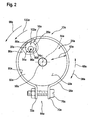
In
Zu Änderung der Querschnittsfläche 22a ist das Kraftschlusselement 20a von einem zylinderförmigen Wälzkörper 32a gebildet und in einem in radialer Richtung 62a nach außen angeordneten Randbereich 86a des Aufnahmeflansches 66a bewegbar in diesem gelagert. Das Kraftschlusselement 20a koppelt dabei kraftschlüssig an das Spannband 28a und/oder den Schutzhaubenkragen 64a der Schutzhaubeneinheit 14a, wobei eine in radialer Richtung 62a nach außen weisende Seite 88a des Wälzkörpers 32a in einer montierten Arbeitsposition der Schutzhaubeneinheit 14a an der Handwerkzeugmaschine 12a an einer in radialer Richtung 62a nach innen gerichteten Oberfläche 90a des Spannbands 28a und/oder des Schutzhaubenkragens 64a der Schutzhaubeneinheit 14a anliegt. Zudem ist das Kraftschlusselement 20a von einem Exzenterelement 34a gebildet und um eine Drehachse 92a, die im Wesentlichen parallel zur Achse 54a der Antriebswelle 50a ausgerichtet ist, drehbar in dem Aufnahmeflansch 66a gelagert. Dabei liegt ein Teilbereich 94a des Exzenterelements 34a in einem regulären Betrieb des Handwerkzeugmaschinensystems 40a an dem Spannband 28a und/oder dem Schutzhaubenkragen 64a an, der einen kürzesten Abstand 96a zur Drehachse 92a aufweist.To change the
Im Falle eines berstenden Werkzeugs 18a im Betrieb der Handwerkzeugmaschine 12a werden Werkzeugteile in einer Rotationsrichtung 98a des Werkzeugs 18a nach außen geschleudert. Trifft eines dieser Werkzeugteile auf die Schutzhaubeneinheit 14a, übersteigt eine auf die Schutzhaubeneinheit 14a übertragene Bewegungsenergie des Werkzeugteils eine Befestigungsenergie der Reibschlussverbindung der Verschlusseinheit 44a zwischen der Schutzhaubeneinheit 14a und der Handwerkzeugmaschine 12a. Die Schutzhaubeneinheit 14a wird daraufhin aus ihrer Arbeitsposition heraus in Rotationsrichtung 98a des Werkzeugs 18a gedreht. Dabei wird das Exzenterelement 34a, das an der in radialer Richtung 62a nach innen gewandten Oberfläche 90a des Spannbands 28a und/oder des Schutzhaubenkragens 64a kraftschlüssig koppelt, um die Drehachse 92a in eine Richtung 100a gedreht, die in Rotationsrichtung 98a des Werkzeugs 18a gerichtet ist, wobei sich das Exzenterelement 34a aufgrund einer Bewegung der Schutzhaubeneinheit 14a an dem Spannband 28a und/oder dem Schutzhaubenkragen 64a abwälzt, so dass das Exzenterelement 34a zusammen mit der Schutzhaubeneinheit 14a bewegt wird. Zusätzlich hierzu ist auch denkbar, dass die in radialer Richtung 62a nach innen gewandte Oberfläche 90a des Spannbands 28a und/oder des Schutzhaubenkragens 64a bzw. eine Außenfläche des Exzenterelements 34a zur Erhöhung eines Kraftschlusses zwischen dem Exzenterelement 34a und dem Spannband 28a und/oder dem Schutzhaubenkragen 64a aufgrund einer speziellen Materialwahl und/oder einer speziellen Oberflächenbearbeitung einen erhöhten Reibungskoeffizienten aufweisen.In the case of a
Aufgrund der Drehung des Exzenterelements 34a wird ein Teilbereich 102a des Exzenterelements 34a, der einen größeren Abstand 96a zur Drehachse 92a aufweist als der Teilbereich 94a mit dem kürzesten Abstand 96a, nach außen gedreht, so dass sich die Querschnittsfläche 22a des Aufnahmeflansches 66a vergrößert und dabei eine Reibungskraft zwischen dem Aufnahmeflansch 66a und dem Spannband 28a zusammen mit dem Schutzhaubenkragen 64a erhöht wird. Dabei wird eine von dem Werkzeugteil auf die Schutzhaubeneinheit 14a übertragene Bewegungsenergie durch die wirkende Reibungskraft teilweise absorbiert und sobald die Reibungskraft gleich einem Restimpuls der Schutzhaubeneinheit 14a entlang der Rotationsrichtung 98a entspricht, in einer verdrehsicheren Verdrehsicherungsposition gehalten.Due to the rotation of the
In einer weiteren Ausgestaltung der Erfindung ist es jederzeit denkbar, eine Anzahl der Exzenterelemente 34a zu erhöhen und/oder eine Anordnung des Exzenterelements 34a innerhalb des Aufnahmeflansches 66a in einer dem Fachmann als sinnvoll erscheinenden Weise zu verändern.In a further embodiment of the invention, it is always conceivable to increase a number of the
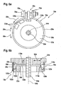
In den
In
In
In
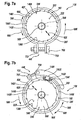
In den
In den
In
Claims (16)
- Protective hood rotation prevention device for a portable power tool (12a - f), in particular for an angle grinder, which is provided to prevent rotation between the portable power tool (12a - f) and a protective hood unit (14a - f), with a force-fitting unit (16a - f), wherein the force-fitting unit (16a - f) is provided to prevent rotation between the portable power tool (12a - f) and the protective hood unit (14a - f) in the event of a rupturing tool (18a - f), wherein the force-fitting unit (16a - f) has at least one force-fitting element (20a - f) which is provided for a change in a shape parameter of the portable power tool (12a - f) and/or the protective hood unit (14a - f), characterized in that the force-fitting unit (16a - f) has at least one force-fitting element (20a - f) which is mounted moveably on the portable power tool (12a - b; 12d - f) and/or on the protective hood unit (14c), wherein the force-fitting element (20a - f) is deflectable out of a rest position by a pulse, transmitted to the protective hood unit, of a tool part of the rupturing tool, and is moveable into a rotation prevention position.
- Protective hood rotation prevention device according to Claim 1, characterized in that the shape parameter comprises a cross-sectional area (22a - b, 22d - f) of a receiving unit (24a - b; 24d - f) of the portable power tool (12a - b; 12d - f) and/or a diameter (26c) of a clamping strap (28c) of the protective hood unit (14c).
- Protective hood rotation prevention device according to Claim 1, characterized in the force-fitting unit (16b) has a guide element (30b) in which the force-fitting element (20b) is mounted in a moveable manner.
- Protective hood rotation prevention device according to Claim 3, characterized in that the force-fitting element (20a; 20b; 20d; 20f) is provided to be coupled at least partially in a form-fitting manner to the protective hood unit (14a; 14b; 14d; 14f).
- Protective hood rotation prevention device according to Claim 3, characterized in that the force-fitting element (20c; 20e; 20f) is provided to be coupled at least partially in a force-fitting manner to the protective hood unit (14e; 14f).
- Protective hood rotation prevention device according to Claim 1, characterized in that the force-fitting element (20a; 20b) is formed by a rolling body (32a; 32b).
- Protective hood rotation prevention device according to Claim 1, characterized in that the force-fitting element (20a; 20c) is formed by an eccentric element (34a; 34c).
- Protective hood rotation prevention device according to Claim 1, characterized in that the force-fitting element (20d; 20e) is formed by a wedge element (36d; 36e).
- Protective hood rotation prevention device according to Claim 8, characterized in that the wedge element (36d; 36e) has a thread for arrangement on a receiving unit (24d; 24e) of the portable power tool (12d; 12e).
- Protective hood rotation prevention device according to Claim 1, characterized in that the force-fitting element (20f) is formed in the manner of a ramp in a circumferential direction (38f).
- Portable power tool system having a portable power tool (12a - f), in particular an angle grinder, a protective hood unit (14a - f) and a protective hood rotation prevention device (10a - f) according to one of the preceding claims, with a force-fitting unit (16a - f), wherein the force-fitting unit (16a - f) is provided to prevent rotation between the portable power tool (12a - f) and the protective hood unit (14a - f) in the event of a rupturing tool (18a - f), and the force-fitting unit (16a - f) has at least one force-fitting element (20a - f) which is deflectable out of a rest position by a pulse, transmitted to the protective hood unit, of a tool part of the rupturing tool, and is moveable into a rotation prevention position.
- Portable power tool system according to Claim 11, characterized in that the force-fitting unit (16a - f) has at least one force-fitting element (20a - f) which is provided for a change in a shape parameter of the portable power tool (12a - f) and/or of the protective hood unit (14a - f).
- Portable power tool system according to Claim 11 or 12, characterized in that the portable power tool (12a - b, 12d - f) has a receiving unit (24a - b; 24d-f) in which the force-fitting element (20a - b; 20d - f) is at least partially mounted.
- Portable power tool system according to Claim 13, characterized in that the receiving unit (24d; 24e) is designed so as to be at least partially slit along a circumferential direction (38d; 38e).
- Portable power tool system according to Claim 13, characterized in that the receiving unit (38f) has an intermediate ring (42f) on which the force-fitting element (20f) is at least partially arranged.
- Portable power tool system according to Claim 15, characterized in that the protective hood unit (14c) has at least one closure unit (44c) on which the force-fitting element (20c) is at least partially arranged.
Applications Claiming Priority (2)
| Application Number | Priority Date | Filing Date | Title |
|---|---|---|---|
| DE200610053305 DE102006053305A1 (en) | 2006-11-13 | 2006-11-13 | Hand tool with protective hood, in particular angle grinder |
| PCT/EP2007/062134 WO2008058909A1 (en) | 2006-11-13 | 2007-11-09 | Protective hood anti-rotation lock |
Publications (2)
| Publication Number | Publication Date |
|---|---|
| EP2106322A1 EP2106322A1 (en) | 2009-10-07 |
| EP2106322B1 true EP2106322B1 (en) | 2014-08-06 |
Family
ID=39004838
Family Applications (5)
| Application Number | Title | Priority Date | Filing Date |
|---|---|---|---|
| EP20070822423 Active EP2106322B1 (en) | 2006-11-13 | 2007-11-09 | Protective hood anti-rotation lock |
| EP07822405.2A Active EP2104590B1 (en) | 2006-11-13 | 2007-11-09 | Protective hood anti-rotation lock |
| EP07822409.4A Active EP2106326B1 (en) | 2006-11-13 | 2007-11-09 | Protective hood securing device |
| EP20070822417 Not-in-force EP2106321B1 (en) | 2006-11-13 | 2007-11-09 | Protective hood anti-rotation lock |
| EP07822425.0A Active EP2106323B1 (en) | 2006-11-13 | 2007-11-09 | Portable power tool system |
Family Applications After (4)
| Application Number | Title | Priority Date | Filing Date |
|---|---|---|---|
| EP07822405.2A Active EP2104590B1 (en) | 2006-11-13 | 2007-11-09 | Protective hood anti-rotation lock |
| EP07822409.4A Active EP2106326B1 (en) | 2006-11-13 | 2007-11-09 | Protective hood securing device |
| EP20070822417 Not-in-force EP2106321B1 (en) | 2006-11-13 | 2007-11-09 | Protective hood anti-rotation lock |
| EP07822425.0A Active EP2106323B1 (en) | 2006-11-13 | 2007-11-09 | Portable power tool system |
Country Status (6)
| Country | Link |
|---|---|
| US (7) | US8465348B2 (en) |
| EP (5) | EP2106322B1 (en) |
| CN (5) | CN101534997B (en) |
| DE (1) | DE102006053305A1 (en) |
| RU (5) | RU2465118C2 (en) |
| WO (5) | WO2008058901A1 (en) |
Families Citing this family (41)
| Publication number | Priority date | Publication date | Assignee | Title |
|---|---|---|---|---|
| DE102006053305A1 (en) * | 2006-11-13 | 2008-05-15 | Robert Bosch Gmbh | Hand tool with protective hood, in particular angle grinder |
| DE102007052684A1 (en) * | 2007-11-05 | 2009-05-07 | Robert Bosch Gmbh | Hand tool |
| DE102009017299A1 (en) * | 2009-04-11 | 2010-10-21 | Metabowerke Gmbh | Protective cover for electric hand tools and electric hand tool |
| JP2010274404A (en) * | 2009-06-01 | 2010-12-09 | Makita Corp | Fixture fall preventing structure for grinding wheel cover in disc grinder |
| DE102009048357A1 (en) * | 2009-10-06 | 2011-04-21 | Metabowerke Gmbh | Electric hand tool |
| JP5544867B2 (en) | 2009-12-21 | 2014-07-09 | 日立工機株式会社 | Grinder |
| JP5587079B2 (en) * | 2010-07-22 | 2014-09-10 | 株式会社マキタ | Movable cover mounting structure and cutting machine |
| JP5684056B2 (en) * | 2010-08-16 | 2015-03-11 | 株式会社マキタ | Hand tool |
| JP5579575B2 (en) * | 2010-11-02 | 2014-08-27 | 株式会社マキタ | Disc grinder |
| US9120202B2 (en) | 2011-06-30 | 2015-09-01 | Black & Decker Inc. | Shield assembly for a power tool |
| JP5959421B2 (en) * | 2011-12-14 | 2016-08-02 | 株式会社マキタ | Grinder |
| DE102011089758A1 (en) * | 2011-12-23 | 2013-06-27 | Robert Bosch Gmbh | Guard anti |
| DE102011089754A1 (en) | 2011-12-23 | 2013-06-27 | Robert Bosch Gmbh | Guard anti |
| DE102012210771A1 (en) * | 2012-06-25 | 2014-01-02 | Robert Bosch Gmbh | Guard device |
| DE102012210767A1 (en) * | 2012-06-25 | 2014-01-02 | Robert Bosch Gmbh | Guard device |
| DE102012210766A1 (en) * | 2012-06-25 | 2014-01-02 | Robert Bosch Gmbh | system |
| US8939816B2 (en) * | 2012-07-02 | 2015-01-27 | Sunmatch Industrial Co., Ltd. | Handheld pneumatic grinder with adjustable wheel guard structure |
| DE102012214834A1 (en) * | 2012-08-21 | 2014-02-27 | Robert Bosch Gmbh | Guard device |
| US10011009B2 (en) * | 2013-11-01 | 2018-07-03 | Robert Bosch Tool Corporation | Guide foot for an oscillating power tool |
| US9475172B2 (en) | 2014-07-15 | 2016-10-25 | Milwaukee Electric Tool Corporation | Adjustable guard for power tool |
| USD744800S1 (en) | 2014-07-16 | 2015-12-08 | Milwaukee Electric Tool Corporation | Power tool blade guard |
| US10201889B2 (en) * | 2014-08-06 | 2019-02-12 | Sparky Guard, LLC | Fully rotatable grinder guard assembly and method for making same |
| CN104568427A (en) * | 2014-11-18 | 2015-04-29 | 中国航空动力机械研究所 | Conical gear shaft twisting-stopping simulation structure device and application |
| US11072052B2 (en) | 2015-04-13 | 2021-07-27 | Black & Decker Inc. | Guard assembly for a power tool |
| US11338426B2 (en) | 2015-11-02 | 2022-05-24 | Black & Decker, Inc. | Cordless power cutter |
| USD800456S1 (en) | 2016-03-04 | 2017-10-24 | The Libman Company | Brush handle |
| CA2959779C (en) | 2016-03-04 | 2019-06-11 | The Libman Company | Scissor-style toilet brush |
| EP3251791B1 (en) | 2016-05-06 | 2019-03-27 | Black & Decker Inc. | Reversible lever for a guard assembly for a power tool |
| EP3300839A1 (en) * | 2016-09-28 | 2018-04-04 | Hilti Aktiengesellschaft | Dust hood for a grinding machine |
| DE102016220343A1 (en) * | 2016-10-18 | 2018-04-19 | Robert Bosch Gmbh | Quick-clamping device for a portable power tool having at least one output shaft which can be driven in rotation, in particular an angle grinder |
| TWI611865B (en) * | 2017-02-23 | 2018-01-21 | Safety cover for grinder | |
| DE102017213746A1 (en) * | 2017-08-08 | 2019-02-14 | Robert Bosch Gmbh | Protective device for a hand tool machine |
| CN107553416B (en) * | 2017-10-25 | 2024-03-15 | 锐奇控股股份有限公司 | Electric tool protection casing adjusting device and electric tool |
| US11077535B2 (en) | 2018-02-14 | 2021-08-03 | Samsung Electronics Co., Ltd. | Process system having locking pin and locking pin |
| DE102018203179A1 (en) * | 2018-03-02 | 2019-09-05 | Robert Bosch Gmbh | Device, in particular handheld power tool management device, and method for monitoring and / or managing a plurality of objects |
| EP3546124A1 (en) * | 2018-03-29 | 2019-10-02 | HILTI Aktiengesellschaft | Angle grinder |
| CN110052933B (en) * | 2018-06-05 | 2021-04-13 | 弗兰克温特 | Grinding disc assembling and locking system containing glass fiber and angle grinder |
| JP7110025B2 (en) * | 2018-08-07 | 2022-08-01 | 株式会社マキタ | Electric tool |
| CN111791129B (en) * | 2019-04-03 | 2023-04-21 | 南京泉峰科技有限公司 | Multifunctional electric tool |
| US11685017B2 (en) | 2020-02-07 | 2023-06-27 | West Bufkin Industries, Llc | Storage shield for angle grinding disc |
| DE202020101891U1 (en) | 2020-04-06 | 2021-07-12 | C. & E. Fein Gmbh | Power tool |
Family Cites Families (60)
| Publication number | Priority date | Publication date | Assignee | Title |
|---|---|---|---|---|
| US2384243A (en) * | 1944-02-16 | 1945-09-04 | Flohr Andrew | Guard for emery wheels and the like |
| US2819570A (en) * | 1957-01-10 | 1958-01-14 | Berne Tocci Guilbert | Safety device for grinding machines |
| US2922261A (en) * | 1957-04-24 | 1960-01-26 | Samuel J Rabkin | Apparatus for removing surface coatings |
| US3068620A (en) * | 1961-02-06 | 1962-12-18 | Tocci-Guilbert Berne | Safety guard for grinding machine |
| DE7028588U (en) * | 1970-07-29 | 1970-12-17 | Fritz Jetzt Fa | PROTECTIVE DEVICE FOR THE CUT-OFF DISC OF A MANUAL CUT-OFF MACHINE. |
| SU495192A1 (en) | 1973-04-11 | 1975-12-15 | В Есоюзный Научно-Исследовательский Институт По Монтажным И Специальным Строительным Работам | Manual machine |
| US4060940A (en) * | 1976-01-13 | 1977-12-06 | The Black And Decker Manufacturing Company | Adjustable guard construction for cut-off machine |
| SU1121131A1 (en) * | 1978-11-09 | 1984-10-30 | Предприятие П/Я Г-4572 | Protective guard for rotors of machines working with shot |
| CS222119B1 (en) * | 1981-03-10 | 1983-04-29 | Borivoj Prazsky | Protective cover of the grinding disc |
| DE3338917A1 (en) * | 1983-10-27 | 1985-05-09 | C. & E. Fein Gmbh & Co, 7000 Stuttgart | PROTECTIVE HOOD FASTENING FOR PORTABLE ANGLE GRINDERS |
| SE443532B (en) * | 1985-02-25 | 1986-03-03 | Kaj Mickos | REMOVABLE PROTECTION FOR CRAFT CRAFTS, ROTABLE TOOLS |
| DE3636601A1 (en) * | 1986-10-28 | 1988-05-05 | Bosch Gmbh Robert | PROTECTIVE COVER FOR GRINDING MACHINES, ESPECIALLY ANGLE GRINDERS, AND THE FASTENING MOUNTING THAT MATCH THEM |
| US4791541A (en) * | 1987-08-28 | 1988-12-13 | Mc Gill Manufacturing Company, Inc. | Protective cage for a lamp |
| SU1611615A1 (en) | 1987-10-13 | 1990-12-07 | Всесоюзный Научно-Исследовательский Инструментальный Институт | Chuck for securing screw taps |
| DE3742430A1 (en) | 1987-12-15 | 1989-06-29 | Waldmann Mechthild | Tool-clamping device for hand-held angle grinding machine (angle grinder) |
| DE3744219A1 (en) * | 1987-12-24 | 1989-07-06 | Fein C & E | HAND GRINDING MACHINE WITH ADJUSTABLE PROTECTIVE COVER |
| DE3940584A1 (en) * | 1989-12-08 | 1991-06-13 | Bosch Gmbh Robert | Adjustable guard for portable grinder - has encircling metal band with tensioning lever to clamp rim of guard onto neck of grinder |
| CN2080440U (en) | 1990-06-14 | 1991-07-10 | 姜会仁 | Safety dust-catching grinding wheel |
| DE9010138U1 (en) | 1990-07-04 | 1990-09-13 | Hu, Cheng Te, Kuan Tien Hsiang, Tainan, Tw | |
| RU2032520C1 (en) * | 1990-10-01 | 1995-04-10 | Казанский Авиационный Институт Им.А.Н.Туполева | Polishing manually-operated machine |
| US5537748A (en) * | 1991-07-09 | 1996-07-23 | Ryobi Limited | Cover structure for electric circular saw |
| US5167215A (en) * | 1991-10-11 | 1992-12-01 | Equipment Development Co., Inc. | Dust removal apparatus for a concrete saw |
| US5440815A (en) * | 1992-04-13 | 1995-08-15 | Inkster; Kevin R. | Guide for rotary cutter tools |
| SE9201990L (en) * | 1992-06-29 | 1993-12-30 | Atlas Copco Tools Ab | Pneumatic rotary grinder |
| US5545082A (en) * | 1994-05-02 | 1996-08-13 | Courson; Michael W. | Dust control system for rotary hand tools |
| DE4422247A1 (en) | 1994-06-24 | 1996-01-04 | Fraunhofer Ges Forschung | Guide and handle for hand=held appliance |
| DE29601002U1 (en) | 1996-01-20 | 1997-05-15 | Bosch Gmbh Robert | Electric hand machine tool |
| SE507264C2 (en) * | 1996-06-13 | 1998-05-04 | Atlas Copco Tools Ab | Handheld power tool |
| DE19834839C2 (en) | 1998-08-01 | 2002-04-11 | C & E Fein Gmbh & Co Kg | Grinder with a removable protective hood |
| RU2152862C2 (en) * | 1998-08-10 | 2000-07-20 | Закрытое Акционерное Общество "Энерпред" | Hand-grinding machine |
| DE10000701A1 (en) * | 2000-01-10 | 2001-07-12 | Bosch Gmbh Robert | Angle grinder protection hood |
| CN1124185C (en) * | 2000-01-27 | 2003-10-15 | 宁波经济技术开发区中强电动工具有限公司 | Automatic locking unit of guard hood for bench of combined saw |
| US6464573B1 (en) * | 2000-06-30 | 2002-10-15 | Porter-Cable Corporation | Guard attachment system with knurled clamp ring |
| WO2002070201A1 (en) * | 2001-03-07 | 2002-09-12 | Sparky Eltos | Safety guard for angle grinders |
| DE10115635C1 (en) * | 2001-03-23 | 2002-10-24 | Flex Elektrowerkzeuge Gmbh | Protective hood for grinding wheel set at right-angles to axis of hand tool is shaped as semicircle and covers arc of circle under motor and has ratchet system to help hold it in place |
| JP3983997B2 (en) * | 2001-04-26 | 2007-09-26 | 株式会社マキタ | Marnoco |
| DE10124439A1 (en) * | 2001-05-18 | 2002-11-21 | Bosch Gmbh Robert | Protective hood of an electric angle grinder has an expanding clamp band held around a shaped housing collar about which it may be turned and clamped |
| DE10158334C1 (en) * | 2001-11-28 | 2003-02-20 | Metabowerke Gmbh | Electric angle grinder has protective hood adjusted relative to spindle neck of angle grinder via releasable cam mechanism |
| US6893334B1 (en) * | 2002-01-24 | 2005-05-17 | J. David Stivers | Rotating guard for angle grinder |
| US6699114B1 (en) * | 2002-04-26 | 2004-03-02 | Benedict Engineering Company, Inc. | Pivotal guards for power hand tools with rotating discs |
| CN2557286Y (en) * | 2002-07-30 | 2003-06-25 | 阿特拉斯·科普柯长春电动工具有限公司 | Universal directional grinding machine |
| DE10259520A1 (en) * | 2002-12-19 | 2004-07-01 | Robert Bosch Gmbh | Electric hand tool |
| SE525836C2 (en) | 2003-03-31 | 2005-05-10 | Atlas Copco Tools Ab | Grinding machine with explosion protection and spindle lock |
| DE10316182A1 (en) * | 2003-04-09 | 2004-10-28 | Robert Bosch Gmbh | Hand grinder with protective hood |
| CN100519064C (en) * | 2003-11-05 | 2009-07-29 | 胡桂强 | Flexible protective cover apparatus of cutter |
| DE10336873B4 (en) * | 2003-08-11 | 2007-09-20 | Hilti Ag | Guard assembly |
| DE10343060A1 (en) * | 2003-09-16 | 2005-04-07 | Robert Bosch Gmbh | Protective cowl for hand power tool especially for angle grinder has an adjustable fitting with a finger pressure ratchet lever engaging ratchet holes in cowl mounting |
| DE10346744A1 (en) | 2003-10-08 | 2005-05-12 | Kippes Gmbh | cutter |
| DE10348395A1 (en) * | 2003-10-17 | 2005-05-19 | Robert Bosch Gmbh | Protective cover for a power tool, power tool and system with protective hood and power tool |
| CN2726843Y (en) * | 2004-06-02 | 2005-09-21 | 墩丰机械工业股份有限公司 | Full sealing type eye protecting cover device of cut-off machine |
| DE102004034441A1 (en) * | 2004-07-16 | 2006-02-16 | Narex Česká Lípa a.s. | Hand tool, in particular angle grinder |
| DE102004047278A1 (en) * | 2004-09-29 | 2006-04-06 | Hilti Ag | Covering device for a tool device |
| DK176122B1 (en) * | 2005-01-21 | 2006-09-11 | Flex Trim As | Apparatus, preferably for grinding a floor surface |
| AU308238S (en) * | 2005-09-30 | 2006-08-01 | Bosch Gmbh Robert | Protection hood for angle grinder |
| DE102005061867A1 (en) * | 2005-12-23 | 2007-07-05 | Robert Bosch Gmbh | Protective hood with clamping device for hand-held tool has turning lock element acting with turn lock counter-element on machine neck of tool |
| EP1908549B1 (en) * | 2006-10-07 | 2010-02-17 | Metabowerke GmbH | Power tool, especially an angle grinder, with a protective cover |
| DE102006053301A1 (en) * | 2006-11-13 | 2008-05-15 | Robert Bosch Gmbh | Hand tool for a rotating tool with protective cover |
| DE102006053303A1 (en) * | 2006-11-13 | 2008-05-15 | Robert Bosch Gmbh | Hand tool for a rotating tool with protective cover |
| DE102007041840A1 (en) * | 2006-11-13 | 2008-05-15 | Robert Bosch Gmbh | Hand tool with protective hood, in particular angle grinder |
| DE102006053305A1 (en) * | 2006-11-13 | 2008-05-15 | Robert Bosch Gmbh | Hand tool with protective hood, in particular angle grinder |
-
2006
- 2006-11-13 DE DE200610053305 patent/DE102006053305A1/en not_active Withdrawn
-
2007
- 2007-11-09 RU RU2009122230/02A patent/RU2465118C2/en not_active IP Right Cessation
- 2007-11-09 EP EP20070822423 patent/EP2106322B1/en active Active
- 2007-11-09 WO PCT/EP2007/062108 patent/WO2008058901A1/en active Application Filing
- 2007-11-09 RU RU2009122232/02A patent/RU2463151C2/en not_active IP Right Cessation
- 2007-11-09 WO PCT/EP2007/062134 patent/WO2008058909A1/en active Application Filing
- 2007-11-09 CN CN2007800421403A patent/CN101534997B/en not_active Expired - Fee Related
- 2007-11-09 RU RU2009122235/02A patent/RU2466848C2/en not_active IP Right Cessation
- 2007-11-09 WO PCT/EP2007/062120 patent/WO2008058904A1/en active Application Filing
- 2007-11-09 CN CNA2007800421121A patent/CN101534995A/en active Pending
- 2007-11-09 CN CN2007800421526A patent/CN101534998B/en active Active
- 2007-11-09 WO PCT/EP2007/062136 patent/WO2008058910A1/en active Application Filing
- 2007-11-09 EP EP07822405.2A patent/EP2104590B1/en active Active
- 2007-11-09 US US12/280,009 patent/US8465348B2/en active Active
- 2007-11-09 EP EP07822409.4A patent/EP2106326B1/en active Active
- 2007-11-09 RU RU2009122212/02A patent/RU2465117C2/en not_active IP Right Cessation
- 2007-11-09 CN CN2007800421140A patent/CN101534996B/en active Active
- 2007-11-09 US US12/282,828 patent/US8562395B2/en not_active Expired - Fee Related
- 2007-11-09 WO PCT/EP2007/062104 patent/WO2008058900A1/en active Application Filing
- 2007-11-09 EP EP20070822417 patent/EP2106321B1/en not_active Not-in-force
- 2007-11-09 CN CN200780042189.9A patent/CN101535002B/en not_active Expired - Fee Related
- 2007-11-09 US US12/293,386 patent/US7955162B2/en not_active Expired - Fee Related
- 2007-11-09 EP EP07822425.0A patent/EP2106323B1/en active Active
- 2007-11-09 US US12/280,850 patent/US8460070B2/en not_active Expired - Fee Related
- 2007-11-09 US US12/293,850 patent/US8221197B2/en active Active
- 2007-11-09 RU RU2009122216/02A patent/RU2464150C2/en not_active IP Right Cessation
-
2011
- 2011-10-17 US US13/274,884 patent/US8231436B2/en active Active
-
2012
- 2012-05-29 US US13/482,121 patent/US8454411B2/en not_active Expired - Fee Related
Also Published As
Similar Documents
| Publication | Publication Date | Title |
|---|---|---|
| EP2106322B1 (en) | Protective hood anti-rotation lock | |
| EP2106325B1 (en) | Portable power tool, especially angle grinder, comprising a protective hood | |
| EP2097220B1 (en) | Portable power tool for a rotating tool comprising a protective hood | |
| EP1908549B1 (en) | Power tool, especially an angle grinder, with a protective cover | |
| EP0339027B1 (en) | Clamping device for releasably holding a tool, in particular a disk | |
| EP2464494B1 (en) | Machine tool having a protective cover | |
| EP1965949B1 (en) | Protective hood with clamping device | |
| EP2897515B1 (en) | Extraction connection system | |
| EP3500401B1 (en) | Power tool | |
| EP2962809B1 (en) | Guard for an electric machine tool, electric machine tool, and system comprising a guard and electric machine tool | |
| EP3500402B1 (en) | Quick tensioning device for a portable machine tool, in particular for an angle grinding machine | |
| EP3383585B1 (en) | Hand-held power tool having at least one machine-side contact element | |
| WO2009059838A1 (en) | Hand-held power tool | |
| DE102010013102A1 (en) | Discharge safety device | |
| EP2548697A2 (en) | Tool holding device, tool holding device-tool combination and machine tool | |
| DE102017213747A1 (en) | Protective device for a hand tool machine | |
| DE10021339A1 (en) | Gear head | |
| EP2794188B1 (en) | Protective hood rotation prevention device | |
| DE202014009916U1 (en) | Hand tool | |
| EP2189244B1 (en) | Angle grinder with protective covering | |
| EP3736093B1 (en) | Fixing device for fixing a chainsaw blade | |
| EP3664964A1 (en) | Protective device for a hand-held power tool | |
| EP3246128A1 (en) | Hand-held machine tool device for mobile positioning of a shaft in a guiding rail | |
| WO2021013628A1 (en) | Machine tool | |
| WO2023099083A1 (en) | Tool interface device, in particular insertion tool hub |
Legal Events
| Date | Code | Title | Description |
|---|---|---|---|
| PUAI | Public reference made under article 153(3) epc to a published international application that has entered the european phase |
Free format text: ORIGINAL CODE: 0009012 |
|
| 17P | Request for examination filed |
Effective date: 20090615 |
|
| AK | Designated contracting states |
Kind code of ref document: A1 Designated state(s): AT BE BG CH CY CZ DE DK EE ES FI FR GB GR HU IE IS IT LI LT LU LV MC MT NL PL PT RO SE SI SK TR |
|
| 17Q | First examination report despatched |
Effective date: 20091102 |
|
| DAX | Request for extension of the european patent (deleted) | ||
| GRAP | Despatch of communication of intention to grant a patent |
Free format text: ORIGINAL CODE: EPIDOSNIGR1 |
|
| INTG | Intention to grant announced |
Effective date: 20140513 |
|
| GRAS | Grant fee paid |
Free format text: ORIGINAL CODE: EPIDOSNIGR3 |
|
| GRAA | (expected) grant |
Free format text: ORIGINAL CODE: 0009210 |
|
| AK | Designated contracting states |
Kind code of ref document: B1 Designated state(s): AT BE BG CH CY CZ DE DK EE ES FI FR GB GR HU IE IS IT LI LT LU LV MC MT NL PL PT RO SE SI SK TR |
|
| REG | Reference to a national code |
Ref country code: GB Ref legal event code: FG4D Free format text: NOT ENGLISH |
|
| REG | Reference to a national code |
Ref country code: CH Ref legal event code: EP Ref country code: AT Ref legal event code: REF Ref document number: 680778 Country of ref document: AT Kind code of ref document: T Effective date: 20140815 |
|
| REG | Reference to a national code |
Ref country code: IE Ref legal event code: FG4D Free format text: LANGUAGE OF EP DOCUMENT: GERMAN |
|
| REG | Reference to a national code |
Ref country code: DE Ref legal event code: R096 Ref document number: 502007013342 Country of ref document: DE Effective date: 20140918 |
|
| REG | Reference to a national code |
Ref country code: NL Ref legal event code: VDEP Effective date: 20140806 |
|
| REG | Reference to a national code |
Ref country code: LT Ref legal event code: MG4D |
|
| PG25 | Lapsed in a contracting state [announced via postgrant information from national office to epo] |
Ref country code: BG Free format text: LAPSE BECAUSE OF FAILURE TO SUBMIT A TRANSLATION OF THE DESCRIPTION OR TO PAY THE FEE WITHIN THE PRESCRIBED TIME-LIMIT Effective date: 20141106 Ref country code: LT Free format text: LAPSE BECAUSE OF FAILURE TO SUBMIT A TRANSLATION OF THE DESCRIPTION OR TO PAY THE FEE WITHIN THE PRESCRIBED TIME-LIMIT Effective date: 20140806 Ref country code: FI Free format text: LAPSE BECAUSE OF FAILURE TO SUBMIT A TRANSLATION OF THE DESCRIPTION OR TO PAY THE FEE WITHIN THE PRESCRIBED TIME-LIMIT Effective date: 20140806 Ref country code: PT Free format text: LAPSE BECAUSE OF FAILURE TO SUBMIT A TRANSLATION OF THE DESCRIPTION OR TO PAY THE FEE WITHIN THE PRESCRIBED TIME-LIMIT Effective date: 20141209 Ref country code: GR Free format text: LAPSE BECAUSE OF FAILURE TO SUBMIT A TRANSLATION OF THE DESCRIPTION OR TO PAY THE FEE WITHIN THE PRESCRIBED TIME-LIMIT Effective date: 20141107 Ref country code: SE Free format text: LAPSE BECAUSE OF FAILURE TO SUBMIT A TRANSLATION OF THE DESCRIPTION OR TO PAY THE FEE WITHIN THE PRESCRIBED TIME-LIMIT Effective date: 20140806 Ref country code: ES Free format text: LAPSE BECAUSE OF FAILURE TO SUBMIT A TRANSLATION OF THE DESCRIPTION OR TO PAY THE FEE WITHIN THE PRESCRIBED TIME-LIMIT Effective date: 20140806 |
|
| PG25 | Lapsed in a contracting state [announced via postgrant information from national office to epo] |
Ref country code: NL Free format text: LAPSE BECAUSE OF FAILURE TO SUBMIT A TRANSLATION OF THE DESCRIPTION OR TO PAY THE FEE WITHIN THE PRESCRIBED TIME-LIMIT Effective date: 20140806 Ref country code: PL Free format text: LAPSE BECAUSE OF FAILURE TO SUBMIT A TRANSLATION OF THE DESCRIPTION OR TO PAY THE FEE WITHIN THE PRESCRIBED TIME-LIMIT Effective date: 20140806 Ref country code: IS Free format text: LAPSE BECAUSE OF FAILURE TO SUBMIT A TRANSLATION OF THE DESCRIPTION OR TO PAY THE FEE WITHIN THE PRESCRIBED TIME-LIMIT Effective date: 20141206 Ref country code: LV Free format text: LAPSE BECAUSE OF FAILURE TO SUBMIT A TRANSLATION OF THE DESCRIPTION OR TO PAY THE FEE WITHIN THE PRESCRIBED TIME-LIMIT Effective date: 20140806 Ref country code: CY Free format text: LAPSE BECAUSE OF FAILURE TO SUBMIT A TRANSLATION OF THE DESCRIPTION OR TO PAY THE FEE WITHIN THE PRESCRIBED TIME-LIMIT Effective date: 20140806 |
|
| PG25 | Lapsed in a contracting state [announced via postgrant information from national office to epo] |
Ref country code: IT Free format text: LAPSE BECAUSE OF FAILURE TO SUBMIT A TRANSLATION OF THE DESCRIPTION OR TO PAY THE FEE WITHIN THE PRESCRIBED TIME-LIMIT Effective date: 20140806 Ref country code: DK Free format text: LAPSE BECAUSE OF FAILURE TO SUBMIT A TRANSLATION OF THE DESCRIPTION OR TO PAY THE FEE WITHIN THE PRESCRIBED TIME-LIMIT Effective date: 20140806 Ref country code: EE Free format text: LAPSE BECAUSE OF FAILURE TO SUBMIT A TRANSLATION OF THE DESCRIPTION OR TO PAY THE FEE WITHIN THE PRESCRIBED TIME-LIMIT Effective date: 20140806 Ref country code: SK Free format text: LAPSE BECAUSE OF FAILURE TO SUBMIT A TRANSLATION OF THE DESCRIPTION OR TO PAY THE FEE WITHIN THE PRESCRIBED TIME-LIMIT Effective date: 20140806 Ref country code: RO Free format text: LAPSE BECAUSE OF FAILURE TO SUBMIT A TRANSLATION OF THE DESCRIPTION OR TO PAY THE FEE WITHIN THE PRESCRIBED TIME-LIMIT Effective date: 20140806 Ref country code: CZ Free format text: LAPSE BECAUSE OF FAILURE TO SUBMIT A TRANSLATION OF THE DESCRIPTION OR TO PAY THE FEE WITHIN THE PRESCRIBED TIME-LIMIT Effective date: 20140806 |
|
| REG | Reference to a national code |
Ref country code: DE Ref legal event code: R097 Ref document number: 502007013342 Country of ref document: DE |
|
| PLBE | No opposition filed within time limit |
Free format text: ORIGINAL CODE: 0009261 |
|
| STAA | Information on the status of an ep patent application or granted ep patent |
Free format text: STATUS: NO OPPOSITION FILED WITHIN TIME LIMIT |
|
| PG25 | Lapsed in a contracting state [announced via postgrant information from national office to epo] |
Ref country code: LU Free format text: LAPSE BECAUSE OF FAILURE TO SUBMIT A TRANSLATION OF THE DESCRIPTION OR TO PAY THE FEE WITHIN THE PRESCRIBED TIME-LIMIT Effective date: 20141109 Ref country code: BE Free format text: LAPSE BECAUSE OF NON-PAYMENT OF DUE FEES Effective date: 20141130 Ref country code: MC Free format text: LAPSE BECAUSE OF FAILURE TO SUBMIT A TRANSLATION OF THE DESCRIPTION OR TO PAY THE FEE WITHIN THE PRESCRIBED TIME-LIMIT Effective date: 20140806 |
|
| REG | Reference to a national code |
Ref country code: CH Ref legal event code: PL |
|
| 26N | No opposition filed |
Effective date: 20150507 |
|
| PG25 | Lapsed in a contracting state [announced via postgrant information from national office to epo] |
Ref country code: LI Free format text: LAPSE BECAUSE OF NON-PAYMENT OF DUE FEES Effective date: 20141130 Ref country code: CH Free format text: LAPSE BECAUSE OF NON-PAYMENT OF DUE FEES Effective date: 20141130 |
|
| REG | Reference to a national code |
Ref country code: IE Ref legal event code: MM4A |
|
| PG25 | Lapsed in a contracting state [announced via postgrant information from national office to epo] |
Ref country code: IE Free format text: LAPSE BECAUSE OF NON-PAYMENT OF DUE FEES Effective date: 20141109 |
|
| REG | Reference to a national code |
Ref country code: FR Ref legal event code: PLFP Year of fee payment: 9 |
|
| PG25 | Lapsed in a contracting state [announced via postgrant information from national office to epo] |
Ref country code: SI Free format text: LAPSE BECAUSE OF FAILURE TO SUBMIT A TRANSLATION OF THE DESCRIPTION OR TO PAY THE FEE WITHIN THE PRESCRIBED TIME-LIMIT Effective date: 20140806 |
|
| REG | Reference to a national code |
Ref country code: AT Ref legal event code: MM01 Ref document number: 680778 Country of ref document: AT Kind code of ref document: T Effective date: 20141109 |
|
| PG25 | Lapsed in a contracting state [announced via postgrant information from national office to epo] |
Ref country code: AT Free format text: LAPSE BECAUSE OF NON-PAYMENT OF DUE FEES Effective date: 20141109 |
|
| PG25 | Lapsed in a contracting state [announced via postgrant information from national office to epo] |
Ref country code: MT Free format text: LAPSE BECAUSE OF FAILURE TO SUBMIT A TRANSLATION OF THE DESCRIPTION OR TO PAY THE FEE WITHIN THE PRESCRIBED TIME-LIMIT Effective date: 20140806 Ref country code: HU Free format text: LAPSE BECAUSE OF FAILURE TO SUBMIT A TRANSLATION OF THE DESCRIPTION OR TO PAY THE FEE WITHIN THE PRESCRIBED TIME-LIMIT; INVALID AB INITIO Effective date: 20071109 Ref country code: TR Free format text: LAPSE BECAUSE OF FAILURE TO SUBMIT A TRANSLATION OF THE DESCRIPTION OR TO PAY THE FEE WITHIN THE PRESCRIBED TIME-LIMIT Effective date: 20140806 |
|
| REG | Reference to a national code |
Ref country code: FR Ref legal event code: PLFP Year of fee payment: 10 |
|
| PGFP | Annual fee paid to national office [announced via postgrant information from national office to epo] |
Ref country code: FR Payment date: 20161124 Year of fee payment: 10 |
|
| PGFP | Annual fee paid to national office [announced via postgrant information from national office to epo] |
Ref country code: GB Payment date: 20171124 Year of fee payment: 11 |
|
| REG | Reference to a national code |
Ref country code: FR Ref legal event code: ST Effective date: 20180731 |
|
| PG25 | Lapsed in a contracting state [announced via postgrant information from national office to epo] |
Ref country code: FR Free format text: LAPSE BECAUSE OF NON-PAYMENT OF DUE FEES Effective date: 20171130 |
|
| GBPC | Gb: european patent ceased through non-payment of renewal fee |
Effective date: 20181109 |
|
| PG25 | Lapsed in a contracting state [announced via postgrant information from national office to epo] |
Ref country code: GB Free format text: LAPSE BECAUSE OF NON-PAYMENT OF DUE FEES Effective date: 20181109 |
|
| REG | Reference to a national code |
Ref country code: DE Ref legal event code: R084 Ref document number: 502007013342 Country of ref document: DE |
|
| PGFP | Annual fee paid to national office [announced via postgrant information from national office to epo] |
Ref country code: DE Payment date: 20230124 Year of fee payment: 16 |
|
| P01 | Opt-out of the competence of the unified patent court (upc) registered |
Effective date: 20230509 |