EP2103992B1 - Informationsaufzeichnungsmedium und Verfahren zu dessen Herstellung - Google Patents
Informationsaufzeichnungsmedium und Verfahren zu dessen Herstellung Download PDFInfo
- Publication number
- EP2103992B1 EP2103992B1 EP09003389.5A EP09003389A EP2103992B1 EP 2103992 B1 EP2103992 B1 EP 2103992B1 EP 09003389 A EP09003389 A EP 09003389A EP 2103992 B1 EP2103992 B1 EP 2103992B1
- Authority
- EP
- European Patent Office
- Prior art keywords
- light
- recording layer
- information
- hologram
- information recording
- Prior art date
- Legal status (The legal status is an assumption and is not a legal conclusion. Google has not performed a legal analysis and makes no representation as to the accuracy of the status listed.)
- Ceased
Links
Images


Classifications
-
- B—PERFORMING OPERATIONS; TRANSPORTING
- B42—BOOKBINDING; ALBUMS; FILES; SPECIAL PRINTED MATTER
- B42D—BOOKS; BOOK COVERS; LOOSE LEAVES; PRINTED MATTER CHARACTERISED BY IDENTIFICATION OR SECURITY FEATURES; PRINTED MATTER OF SPECIAL FORMAT OR STYLE NOT OTHERWISE PROVIDED FOR; DEVICES FOR USE THEREWITH AND NOT OTHERWISE PROVIDED FOR; MOVABLE-STRIP WRITING OR READING APPARATUS
- B42D25/00—Information-bearing cards or sheet-like structures characterised by identification or security features; Manufacture thereof
- B42D25/20—Information-bearing cards or sheet-like structures characterised by identification or security features; Manufacture thereof characterised by a particular use or purpose
-
- B—PERFORMING OPERATIONS; TRANSPORTING
- B42—BOOKBINDING; ALBUMS; FILES; SPECIAL PRINTED MATTER
- B42D—BOOKS; BOOK COVERS; LOOSE LEAVES; PRINTED MATTER CHARACTERISED BY IDENTIFICATION OR SECURITY FEATURES; PRINTED MATTER OF SPECIAL FORMAT OR STYLE NOT OTHERWISE PROVIDED FOR; DEVICES FOR USE THEREWITH AND NOT OTHERWISE PROVIDED FOR; MOVABLE-STRIP WRITING OR READING APPARATUS
- B42D25/00—Information-bearing cards or sheet-like structures characterised by identification or security features; Manufacture thereof
- B42D25/30—Identification or security features, e.g. for preventing forgery
- B42D25/324—Reliefs
-
- B—PERFORMING OPERATIONS; TRANSPORTING
- B42—BOOKBINDING; ALBUMS; FILES; SPECIAL PRINTED MATTER
- B42D—BOOKS; BOOK COVERS; LOOSE LEAVES; PRINTED MATTER CHARACTERISED BY IDENTIFICATION OR SECURITY FEATURES; PRINTED MATTER OF SPECIAL FORMAT OR STYLE NOT OTHERWISE PROVIDED FOR; DEVICES FOR USE THEREWITH AND NOT OTHERWISE PROVIDED FOR; MOVABLE-STRIP WRITING OR READING APPARATUS
- B42D25/00—Information-bearing cards or sheet-like structures characterised by identification or security features; Manufacture thereof
- B42D25/20—Information-bearing cards or sheet-like structures characterised by identification or security features; Manufacture thereof characterised by a particular use or purpose
- B42D25/21—Information-bearing cards or sheet-like structures characterised by identification or security features; Manufacture thereof characterised by a particular use or purpose for multiple purposes
-
- B—PERFORMING OPERATIONS; TRANSPORTING
- B42—BOOKBINDING; ALBUMS; FILES; SPECIAL PRINTED MATTER
- B42D—BOOKS; BOOK COVERS; LOOSE LEAVES; PRINTED MATTER CHARACTERISED BY IDENTIFICATION OR SECURITY FEATURES; PRINTED MATTER OF SPECIAL FORMAT OR STYLE NOT OTHERWISE PROVIDED FOR; DEVICES FOR USE THEREWITH AND NOT OTHERWISE PROVIDED FOR; MOVABLE-STRIP WRITING OR READING APPARATUS
- B42D25/00—Information-bearing cards or sheet-like structures characterised by identification or security features; Manufacture thereof
- B42D25/30—Identification or security features, e.g. for preventing forgery
- B42D25/328—Diffraction gratings; Holograms
-
- B—PERFORMING OPERATIONS; TRANSPORTING
- B42—BOOKBINDING; ALBUMS; FILES; SPECIAL PRINTED MATTER
- B42D—BOOKS; BOOK COVERS; LOOSE LEAVES; PRINTED MATTER CHARACTERISED BY IDENTIFICATION OR SECURITY FEATURES; PRINTED MATTER OF SPECIAL FORMAT OR STYLE NOT OTHERWISE PROVIDED FOR; DEVICES FOR USE THEREWITH AND NOT OTHERWISE PROVIDED FOR; MOVABLE-STRIP WRITING OR READING APPARATUS
- B42D25/00—Information-bearing cards or sheet-like structures characterised by identification or security features; Manufacture thereof
- B42D25/40—Manufacture
- B42D25/405—Marking
- B42D25/415—Marking using chemicals
-
- G—PHYSICS
- G03—PHOTOGRAPHY; CINEMATOGRAPHY; ANALOGOUS TECHNIQUES USING WAVES OTHER THAN OPTICAL WAVES; ELECTROGRAPHY; HOLOGRAPHY
- G03F—PHOTOMECHANICAL PRODUCTION OF TEXTURED OR PATTERNED SURFACES, e.g. FOR PRINTING, FOR PROCESSING OF SEMICONDUCTOR DEVICES; MATERIALS THEREFOR; ORIGINALS THEREFOR; APPARATUS SPECIALLY ADAPTED THEREFOR
- G03F7/00—Photomechanical, e.g. photolithographic, production of textured or patterned surfaces, e.g. printing surfaces; Materials therefor, e.g. comprising photoresists; Apparatus specially adapted therefor
- G03F7/004—Photosensitive materials
- G03F7/008—Azides
- G03F7/012—Macromolecular azides; Macromolecular additives, e.g. binders
-
- G—PHYSICS
- G03—PHOTOGRAPHY; CINEMATOGRAPHY; ANALOGOUS TECHNIQUES USING WAVES OTHER THAN OPTICAL WAVES; ELECTROGRAPHY; HOLOGRAPHY
- G03H—HOLOGRAPHIC PROCESSES OR APPARATUS
- G03H1/00—Holographic processes or apparatus using light, infrared or ultraviolet waves for obtaining holograms or for obtaining an image from them; Details peculiar thereto
- G03H1/0005—Adaptation of holography to specific applications
- G03H1/0011—Adaptation of holography to specific applications for security or authentication
-
- G—PHYSICS
- G03—PHOTOGRAPHY; CINEMATOGRAPHY; ANALOGOUS TECHNIQUES USING WAVES OTHER THAN OPTICAL WAVES; ELECTROGRAPHY; HOLOGRAPHY
- G03H—HOLOGRAPHIC PROCESSES OR APPARATUS
- G03H1/00—Holographic processes or apparatus using light, infrared or ultraviolet waves for obtaining holograms or for obtaining an image from them; Details peculiar thereto
- G03H1/26—Processes or apparatus specially adapted to produce multiple sub- holograms or to obtain images from them, e.g. multicolour technique
-
- G—PHYSICS
- G06—COMPUTING OR CALCULATING; COUNTING
- G06K—GRAPHICAL DATA READING; PRESENTATION OF DATA; RECORD CARRIERS; HANDLING RECORD CARRIERS
- G06K19/00—Record carriers for use with machines and with at least a part designed to carry digital markings
- G06K19/02—Record carriers for use with machines and with at least a part designed to carry digital markings characterised by the selection of materials, e.g. to avoid wear during transport through the machine
-
- G—PHYSICS
- G06—COMPUTING OR CALCULATING; COUNTING
- G06K—GRAPHICAL DATA READING; PRESENTATION OF DATA; RECORD CARRIERS; HANDLING RECORD CARRIERS
- G06K19/00—Record carriers for use with machines and with at least a part designed to carry digital markings
- G06K19/06—Record carriers for use with machines and with at least a part designed to carry digital markings characterised by the kind of the digital marking, e.g. shape, nature, code
- G06K19/08—Record carriers for use with machines and with at least a part designed to carry digital markings characterised by the kind of the digital marking, e.g. shape, nature, code using markings of different kinds or more than one marking of the same kind in the same record carrier, e.g. one marking being sensed by optical and the other by magnetic means
- G06K19/10—Record carriers for use with machines and with at least a part designed to carry digital markings characterised by the kind of the digital marking, e.g. shape, nature, code using markings of different kinds or more than one marking of the same kind in the same record carrier, e.g. one marking being sensed by optical and the other by magnetic means at least one kind of marking being used for authentication, e.g. of credit or identity cards
- G06K19/16—Record carriers for use with machines and with at least a part designed to carry digital markings characterised by the kind of the digital marking, e.g. shape, nature, code using markings of different kinds or more than one marking of the same kind in the same record carrier, e.g. one marking being sensed by optical and the other by magnetic means at least one kind of marking being used for authentication, e.g. of credit or identity cards the marking being a hologram or diffraction grating
-
- B42D2033/14—
-
- B42D2035/50—
-
- G—PHYSICS
- G03—PHOTOGRAPHY; CINEMATOGRAPHY; ANALOGOUS TECHNIQUES USING WAVES OTHER THAN OPTICAL WAVES; ELECTROGRAPHY; HOLOGRAPHY
- G03H—HOLOGRAPHIC PROCESSES OR APPARATUS
- G03H1/00—Holographic processes or apparatus using light, infrared or ultraviolet waves for obtaining holograms or for obtaining an image from them; Details peculiar thereto
- G03H1/02—Details of features involved during the holographic process; Replication of holograms without interference recording
- G03H1/024—Hologram nature or properties
- G03H1/0244—Surface relief holograms
-
- G—PHYSICS
- G03—PHOTOGRAPHY; CINEMATOGRAPHY; ANALOGOUS TECHNIQUES USING WAVES OTHER THAN OPTICAL WAVES; ELECTROGRAPHY; HOLOGRAPHY
- G03H—HOLOGRAPHIC PROCESSES OR APPARATUS
- G03H1/00—Holographic processes or apparatus using light, infrared or ultraviolet waves for obtaining holograms or for obtaining an image from them; Details peculiar thereto
- G03H1/0005—Adaptation of holography to specific applications
- G03H1/0011—Adaptation of holography to specific applications for security or authentication
- G03H2001/0016—Covert holograms or holobjects requiring additional knowledge to be perceived, e.g. holobject reconstructed only under IR illumination
-
- G—PHYSICS
- G03—PHOTOGRAPHY; CINEMATOGRAPHY; ANALOGOUS TECHNIQUES USING WAVES OTHER THAN OPTICAL WAVES; ELECTROGRAPHY; HOLOGRAPHY
- G03H—HOLOGRAPHIC PROCESSES OR APPARATUS
- G03H1/00—Holographic processes or apparatus using light, infrared or ultraviolet waves for obtaining holograms or for obtaining an image from them; Details peculiar thereto
- G03H1/02—Details of features involved during the holographic process; Replication of holograms without interference recording
- G03H2001/026—Recording materials or recording processes
- G03H2001/0264—Organic recording material
-
- G—PHYSICS
- G03—PHOTOGRAPHY; CINEMATOGRAPHY; ANALOGOUS TECHNIQUES USING WAVES OTHER THAN OPTICAL WAVES; ELECTROGRAPHY; HOLOGRAPHY
- G03H—HOLOGRAPHIC PROCESSES OR APPARATUS
- G03H1/00—Holographic processes or apparatus using light, infrared or ultraviolet waves for obtaining holograms or for obtaining an image from them; Details peculiar thereto
- G03H1/26—Processes or apparatus specially adapted to produce multiple sub- holograms or to obtain images from them, e.g. multicolour technique
- G03H2001/2625—Nature of the sub-holograms
- G03H2001/2635—Mixed volume and surface relief holograms
-
- G—PHYSICS
- G03—PHOTOGRAPHY; CINEMATOGRAPHY; ANALOGOUS TECHNIQUES USING WAVES OTHER THAN OPTICAL WAVES; ELECTROGRAPHY; HOLOGRAPHY
- G03H—HOLOGRAPHIC PROCESSES OR APPARATUS
- G03H2210/00—Object characteristics
- G03H2210/20—2D object
- G03H2210/22—2D SLM object wherein the object beam is formed of the light modulated by the SLM
-
- G—PHYSICS
- G03—PHOTOGRAPHY; CINEMATOGRAPHY; ANALOGOUS TECHNIQUES USING WAVES OTHER THAN OPTICAL WAVES; ELECTROGRAPHY; HOLOGRAPHY
- G03H—HOLOGRAPHIC PROCESSES OR APPARATUS
- G03H2250/00—Laminate comprising a hologram layer
- G03H2250/39—Protective layer
-
- G—PHYSICS
- G03—PHOTOGRAPHY; CINEMATOGRAPHY; ANALOGOUS TECHNIQUES USING WAVES OTHER THAN OPTICAL WAVES; ELECTROGRAPHY; HOLOGRAPHY
- G03H—HOLOGRAPHIC PROCESSES OR APPARATUS
- G03H2260/00—Recording materials or recording processes
- G03H2260/30—Details of photosensitive recording material not otherwise provided for
- G03H2260/35—Rewritable material allowing several record and erase cycles
Definitions
- the present invention relates to an information recording medium usable as a personal authentication medium such as a license, credit card, or membership card, and a method of manufacturing the same.
- Various forgery/alteration preventing means are conventionally used in personal authentication media such as a license, credit card, and membership card.
- a rainbow hologram that is a relief hologram having a metal reflecting layer is formed on the surface of a credit card as a structure for visually determining the authenticity of the card. Since this rainbow hologram formed on the card can optically be forged, demands have arisen for an advanced technique as a forgery preventing means.
- Japanese Patent No. 3563774 has disclosed an information recording medium in which a region having a first light-diffracting structure from which recorded information can mechanically be read and a region having a second light-diffracting structure from which recorded information can visually be read are alternately formed in a single light-diffracting structure formation layer so as not to superpose each other.
- the first light-diffracting structure is a hologram from which recorded information can be read with only highly coherent light, it is visually difficult to perceive that optically readable information is recorded. This makes forgery difficult.
- the second light-diffracting structure is a hologram from which recorded information can visually be read with white-light illumination, no special apparatus is necessary in visual authentication.
- both the first and second light-diffracting structures do not superpose each other, no cloudiness occurs due to superposition of the two light-diffracting structures. Accordingly, operation errors hardly occur during mechanical reading.
- both the first and second light-diffracting structures contain permanent information, so the medium can easily be duplicated if the recorded information is revealed.
- variable information can be recorded instead of permanent information. This can make duplication difficult. Since information is rewritable, however, if visually readable information is rewritten, the information cannot visually be distinguished from authentic information. This makes the medium vulnerable to alteration.
- US 2005/0208387 A1 discloses an optical recording material which includes at least one of a polymer and an oligomer, the at least one of a polymer and an oligomer comprising a photoresponsive group.
- the optical recording material records, information through change in at least one of absorption, refractive index and shape due to irradiation of light thereto.
- a main chain of the at least one of a polymer and an oligomer has a side chain comprising a mesogenic unit linked thereto.
- the side chain comprises a least two flexible spacer groups introduced thereto, the spacer groups having lengths different from each other.
- the present invention has been made in consideration of the above situation, and has as its object to provide an information recording medium that is hardly forged and altered.
- An information recording medium manufacturing method of the present invention comprising:
- An information recording medium of the present invention comprises a support, a recording layer formed on the support and containing a polymer compound having an azobenzene structure, a first light-diffracting structure having a three-dimensional shape being formed on a surface of the recording layer, and a second light-diffracting structure having a refractive index change being formed inside the recording layer, and a deformation preventing layer formed on the recording layer to fix the three-dimensional shape.
- An information recording medium that is hardly forged or altered can be obtained by using the present invention.
- An information recording medium manufacturing method of the present invention includes steps of forming, on a support, a recording layer containing a polymer compound having an azobenzene structure, irradiating the recording layer with first writing light to deform the recording layer by moving molecules of the polymer compound having an azobenzene structure, thereby forming a first light-diffracting structure having a three-dimensional shape on the surface of the recording layer, and forming a second light-diffracting structure by irradiating the recording layer with second writing light, wherein the three-dimensional shape as the first light-diffracting structure is fixed by forming a deformation preventing layer on the surface of the recording layer before the recording layer is irradiated with the second writing light, so the second light-diffracting structure having a refractive index change can be formed inside the recording layer by inhibiting deformation caused by the movement of molecules of the polymer compound having an azobenzene structure when the second writing light is applied.
- a polymer compound having an azobenzene structure represented by formula (1) below is used as the recording layer. Also, the present invention uses the characteristics of this compound. (wherein R1 is an electron releasing group, R3 is an electron withdrawing group, each of X and Y is another constituent element that forms a single bond or polymer chain, and each of m and n is an integer of 1 or more).
- This phenomenon is as follows.
- the surface portion senses the intensity of the light, and molecules move from a high-intensity portion to a low-intensity portion, thereby forming a three-dimensional shape.
- the three-dimensional shape thus formed on the surface can be erased by applying light having another wavelength or by heating. It also possible to accurately record the shape and polarized state of a beam on the three-dimensional structure, and reproduce them from it.
- the refractive index change formed as the second light-diffracting structure inside the recording layer occurs when those molecules of the polymer compound having an azobenzene structure, which are forcedly inhibited from moving, point in the direction of an electric field.
- the information recording medium of the present invention is one information recording medium formed by the above manufacturing method, and includes a support, a recording layer formed on the support and containing a polymer compound having an azobenzene structure, and a deformation preventing layer formed on the recording layer.
- the recording layer has a first light-diffracting structure on the surface, and a second light-diffracting structure in the interior.
- the "surface” herein mentioned is a surface opposite to a surface facing the support. In other words, this surface is the interface between the deformation preventing layer and recording layer.
- the first light-diffracting structure is characterized by a shape, i.e., a relief pattern. This relief pattern is obtained by moving molecules in the polymer compound having an azobenzene structure by irradiating the compound with first writing light, thereby deforming the recording layer.
- the first light-diffracting structure is unrewritable as it is fixed by the deformation preventing layer.
- the second light-diffracting structure is characterized by a physical property, i.e., a refractive index change.
- This refractive index change is produced by forcedly inhibiting the movement of molecules in the polymer compound having an azobenzene structure by irradiating the compound with second writing light, thereby changing the direction of the molecules in the recording layer in accordance with the second writing light. Accordingly, the second light-diffracting structure has no shape feature. The second light-diffracting structure can be rewritten by further applying the second writing light.
- the polymer compound having an azobenzene structure is used as the recording layer and irradiated with the first writing light, thereby forming the relief pattern on the surface of the recording layer by using the physical property of the polymer compound having an azobenzene structure.
- the deformation preventing layer is formed on the relief pattern to fix the shape, and the second writing light is applied to forcedly inhibit the movement of molecules and deformation caused by the molecular movement, thereby changing only the direction of the molecules. This makes it possible to produce a refractive index change corresponding to the second writing light in the recording layer.
- the relief pattern can be used as visually readable unrewritable information, and the refractive index change can be used as readable rewritable information.
- the information recording medium thus obtained is hardly forged or altered.
- Highly coherent light can be used as the first writing light.
- Hologram recording can be performed on the recording layer by using coherent light.
- the first light-diffracting structure can be a hologram or diffraction grating that can visually be read when irradiated with white light.
- Highly coherent light can be used as the second writing light.
- Hologram recording can be performed on the recording layer by using coherent light.
- the second light-diffracting structure can be a hologram or diffraction grating that can be read with highly coherent light.
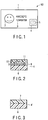
- FIG. 1 is a front view of an ID card as an example of a personal authentication medium to which the information recording medium according to the present invention is applicable.
- a color face image 2 of the holder of the ID card and character information 3 such as the name, date of birth, and ID number of the holder are printed on a card substrate 1 of an ID card 50, and an information recording medium 4 according to the present invention is adhered to a portion of a region except for the region where the color face image 2 and character information 3 are recorded.
- the information recording medium 4 is adhered as a seal on the card substrate 1 in this embodiment, but the recording layer, deformation preventing layer, and the like used in the present invention may also be directly formed by using the card substrate as a support.
- the information recording medium 4 has an image obtained by downsizing the face image of the holder, as a visually readable hologram 5.
- the visually readable hologram 5 is a hologram formed by a relief pattern.
- the color face image 2 is formed by, e.g., a sublimation heat transfer printing method.
- the color face image 2 may also be formed by various printing methods such as an inkjet printing method.
- the character information 3 can be formed by, e.g., a melting heat transfer printing method.
- the character information 3 may also be formed by various printing methods such as an inkjet printing method.
- FIG. 2 is a schematic sectional view showing an example of the information recording medium of the present invention.
- a recording layer 8 containing a polymer compound having an azobenzene structure and a deformation preventing layer 11 are sequentially formed on a substrate 6.
- the recording layer 8 containing the polymer compound having an azobenzene structure has a hologram 10 that is a visually readable three-dimensional relief pattern.
- the recording layer 8 also has a hologram 9 that is a visually unreadable, but readable refractive index change pattern.
- the relief pattern hologram 10 is unrewritable because it is fixed by the deformation preventing layer 11, so azobenzene molecules cannot move even when irradiated with light. This makes alteration difficult.
- the refractive index change pattern hologram 9 is rewritable because it is formed inside the recording layer 8, so nothing interferes with the formation of the hologram 9. For example, if the name of the holder or the valid period of the ID card has changed, the information of the refractive index change pattern hologram 9 can be rewritten.
- a magnetic memory, IC memory or the like is formed in the ID card, the authenticity of the ID card can be determined by collating information stored in the memory with the information recorded in the hologram 9.
- the second writing light can be applied not only from the side of the relief pattern hologram 10 but also from the side of the substrate 6. Therefore, the substrate 6 can be transparent in order to well transmit the second writing light.
- the information recording medium 4 can be formed on the ID card 50 by applying, for example, an adhesive or the like on the surface of the substrate 6, and adhering the substrate 6 on the card substrate 1.
- the information recording medium 4 can be formed by using the card substrate 1 as the substrate 6.
- a material usable as the deformation preventing layer 11 is required to be applicable on the relief pattern, and have hardness that can well inhibit the movement of molecules of the azobenzene polymer compound.
- the material can also have transparency with which it is well possible to visually recognize the relief pattern on the surface of the recording layer 8.
- a liquid material can be selected in order to apply the material on the relief pattern. As a liquid material that can readily be set after being applied, it is possible to use, e.g., a photo-setting resin or thermosetting resin.
- thermosetting resin are an alkyd resin, amino-alkyd resin, epoxy resin-fatty acid ester, epoxy resin, polyurethane family, acrylic resin family, acrylic-urethane resin, vinyl resin family, fluorine resin family, polysiloxane family, and acryl-siloxane-based resin.
- the photo-setting resin it is possible to use a resin which is made of a photo-setting oligomer, monomer, photoreaction initiator, body pigment, and other additives, and in which the photo-setting oligomer and monomer react with each other by photo-setting, thereby forming a three-dimensional network structure.
- the photo-setting resin it is possible to use, e.g., an ultraviolet-curing resin.
- An example of the ultraviolet-curing resin is (meta)acrylic ester of trifunctional or higher alcohol.
- Examples of this (meta)acrylic ester are pentaerythritol triacrylate, pentaerythritol trimethacrylate, pentaerythritol tetraacrylate, pentaerythritol tetramethacrylate, trimethylolpropane triacrylate, trimethylolpropane trimethacrylate, dipentaerythritol triacrylate, dipentaerythritol hexaacrylate, dipentaerythritol hexamethacrylate, dipentaerythritol pentamethacrylate, pentaerythritol polyacrylate, and dipentaerythritol polyacrylate.
- a photoreaction initiator can be added to the ultraviolet-curing resin.
- photoreaction initiator examples include benzophenones, acetophenones, benzoins, thioxantons, azo compounds, Michler's ketone, benzyl, benzoinalkylether, benzyldimethylketal, and tetramethylthiuram monosulfide.
- FIG. 3 is a schematic sectional view showing the state in which the information recording medium shown in FIG. 2 is unrecorded.
- An unrecorded information recording medium 4' has a substrate 6 as a resin sheet, and an organic compound recording layer 7 formed on the substrate 6 and containing an azobenzene structure.
- the substrate 6 may be the ID card substrate 1 or another resin sheet.
- a refractive index change pattern (to be described later)
- writing light can be applied not from the surface on which the relief pattern hologram is formed but from the opposite surface. Therefore, the substrate 6 can be transparent.
- the substrate 6 it is possible to use a resin sheet made of, e.g., polyvinyl chloride or a polyethyleneterephthalate resin. In this embodiment, a 50- ⁇ m thick polyethyleneterephthalate resin sheet was used.
- the recording layer 7 can be formed by dissolving a polymer compound containing an azobenzene structure in a solvent such as chloroform or dichloromethane at a concentration of 1 to 30 mass%, and forming a thin film of the solution by, e.g., gravure printing, roll printing, or inkjet printing.
- the thickness of the recording layer 7 can properly be changed in accordance with the relief pattern, and can be set to, e.g., 1 to 5 ⁇ m.
- the pattern pitch of the relief pattern hologram 10 is 1 ⁇ m. Since the refractive index change pattern must be formed inside the recording layer, the thickness of the recording layer 7 can be set at 3 ⁇ m, i.e., a value three times as large as the pitch.
- Examples of the polymer compound containing an azobenzene structure usable in the present invention are a compound represented by formula (2) below, and PVA (PolyVinyl Alcohol) formed by dispersing methyl orange.
- PVA PolyVinyl Alcohol
- FIG. 4 is a schematic view of an example of an information recording apparatus to which the present invention is applicable.
- FIG. 5 is a schematic view of an example of an information recording method using the information recording apparatus shown in FIG. 4 .
- an information recording apparatus 60 has rollers 15a to 15d for conveying, e.g., the information recording medium 4' as shown in FIG. 2 to each means, a relief formation mechanism 12 for forming a relief pattern hologram, a resin film formation mechanism 13 for forming a resin film on the surface on which the relief pattern hologram is formed, and a refractive index change formation mechanism 14 for forming a refractive index change pattern hologram.
- the information recording medium 4' is first inserted into a tray (not shown), and conveyed to the relief formation mechanism 12 by the conveyor roller 15a.
- the relief formation mechanism 12 forms, e.g., a relief pattern hologram (S1).
- the conveyor roller 15b conveys the information recording medium to the deformation preventing layer formation mechanism 13.
- the deformation preventing layer formation mechanism 13 coats the relief pattern hologram formation surface with a deformation preventing layer made of, e.g., a photo-setting resin (S2).
- S2 photo-setting resin
- the deformation preventing layer is then set by light irradiation (S3).
- the conveyor roller 15c conveys the information recording medium to the refractive index change formation mechanism 14.
- the refractive index change formation mechanism 14 forms a refractive index change pattern hologram (S4). After that, the conveyor roller 15d discharges the information recording medium to a tray (not shown). In this manner, the unrewritable relief pattern hologram 10 and rewritable refractive index change pattern hologram 9 are formed in the information recording medium 4.
- FIG. 6 is a schematic view showing an example of the relief pattern formation mechanism shown in FIG. 4 .
- a light source 16 need only emit coherent light having a wavelength sensitive to an organic compound containing an azobenzene structure.
- an oscillation line of 515 nm of an argon ion laser was used as highly coherent light.
- the laser beam from the light source 16 is transmitted through a half mirror 17, reflected by a mirror 18, converted into parallel light by a lens 19, and applied to a spatial optical modulator 20.
- a voltage address type liquid-crystal panel or the like can be used as the spatial optical modulator 20.
- a liquid-crystal layer of the spatial optical modulator can modulate the amplitude or intensity of incident light.
- a computer 23 converts information to be recorded in a relief hologram into a binary image made up of black and white dots.
- the image is output from the computer 23 to the spatial optical modulator 20, and displayed.
- the intensity of light entering the spatial optical modulator 20 is two-dimensionally modulated.
- the information to be recorded was an image obtained by downsizing the face image of the holder of the ID card. Then, the information recording medium 4 is irradiated with signal light that is the light whose intensity is two-dimensionally modulated in accordance with the information to be recorded.
- the laser beam from the light source 16 is reflected by the half mirror 17 and a mirror 21, converted into parallel light by a lens 22, and applied as reference light to the information recording medium 4.
- the signal light and reference light interfere with each other, and the signal light holding the face image data is recorded as the relief pattern hologram 10.
- the image information is displayed on the spatial optical modulator and the hologram is formed by using the information in this embodiment, but the present invention is not limited to this.
- An example is a computer generated hologram. That is, it is also possible to calculate interference fringes of light by a computer, and directly write the fringe pattern by a laser beam.
- FIG. 7 is a schematic view showing an example of the refractive index change formation mechanism shown in FIG. 4 .
- a light source 24 need only emit coherent light having a wavelength sensitive to an organic compound containing an azobenzene structure.
- An oscillation line of 515 nm of an argon ion laser was used as highly coherent light in this mechanism as well.
- the laser beam from the light source 24 is transmitted through a half mirror 25, reflected by a mirror 26, converted into parallel light by a lens 27, and applied to a spatial optical modulator 28.
- a voltage address type liquid-crystal panel was used as the spatial optical modulator 28 as in the configuration shown in FIG. 6 .
- a computer 23 converts information to be recorded in a refractive index change pattern hologram into a binary image made up of black and white dots. The image is output from the computer 23 to the spatial optical modulator 28, and displayed.
- the intensity of light entering the spatial optical modulator 28 is two-dimensionally modulated.
- the information to be recorded was a QR code image as a two-dimensional barcode obtained by converting the name, birth year/date, and ID number of the holder of the ID card into code information.
- the information recording medium 4 is irradiated with signal light obtained by performing Fourier transform, by a Fourier transform lens 29, on the light whose intensity is two-dimensionally modulated in accordance with the information to be recorded.
- the laser beam from the light source 24 is reflected by the half mirror 25 and a mirror 30, converted into parallel light by a lens 31, Fourier-transformed by a Fourier transform lens 32, and applied as reference light to the information recording medium 4.
- the signal light and reference light interfere with each other, and the signal light holding the QR code data is recorded as the refractive index change pattern hologram 9.
- the image information is displayed on the spatial optical modulator and the hologram is formed by using the information in this embodiment, but the present invention is not limited to this.
- An example is a computer generated hologram. That is, it is also possible to calculate interference fringes of light by a computer, and directly write the fringe pattern by a laser beam.
- the signal light and reference light described above can be applied from the surface opposite to the relief pattern hologram formation surface.
- the signal light and reference light may also be applied from the relief pattern hologram formation surface, the relief pattern may diffract the light and decrease the information recording efficiency.
- FIG. 8 is a schematic view showing an example of the deformation preventing layer formation mechanism shown in FIG. 4 .
- Examples of the method of forming the deformation preventing layer on the surface of the relief pattern hologram 10 are flat screen printing, inkjet printing, and rubber roller printing. In this embodiment, inkjet printing was used.
- FIG. 8 is a schematic view showing an example of the deformation preventing layer formation mechanism shown in FIG. 4 .
- An ink tank 34 is connected to an inkjet printing head 33, and a liquid prepared by dispersing an ultraviolet-curing resin in a solvent is placed in the ink tank 34.
- the inkjet printing head sprays droplets made of the ultraviolet-curing resin onto the relief pattern hologram 10 formation surface of the information recording medium, thereby forming a deformation preventing layer.
- This deformation preventing layer need only have a thickness with which the relief pattern is completely buried. In this embodiment, the thickness was 2 ⁇ m.
- An ultraviolet lamp 35 irradiates the ultraviolet-curing resin solution coating layer formation surface with ultraviolet radiation, thereby curing the ultraviolet-curing resin solution. In this way, the relief pattern hologram 10 can be fixed by the deformation preventing layer 11, and made unrewritable.
- FIG. 9 is a schematic view of another example of the deformation preventing layer formation mechanism shown in FIG. 4 .
- This deformation preventing layer formation mechanism uses a thermosetting resin.
- An ink tank 34 is connected to an inkjet printing head 33, and a liquid prepared by dispersing a thermosetting resin in a solvent is placed in the ink tank 34.
- the inkjet printing head 33 sprays droplets made of the ultraviolet-curing resin onto the relief pattern hologram 10 formation surface of the information recording medium, thereby forming a deformation preventing layer.
- This deformation preventing layer need only have a thickness with which the relief pattern 10 is completely buried. In this embodiment, the thickness was 2 ⁇ m.
- the information recording medium 4 is sandwiched between a counter roller 37 and heat roller 36 such that the heat roller 36 comes in contact with the thermosetting resin coating layer formation surface, and the thermosetting resin coating layer is thermally set. In this manner, the relief pattern hologram 10 can be fixed by the deformation preventing layer 11, and made unrewritable.
Landscapes
- Physics & Mathematics (AREA)
- General Physics & Mathematics (AREA)
- Engineering & Computer Science (AREA)
- Theoretical Computer Science (AREA)
- Spectroscopy & Molecular Physics (AREA)
- Computer Security & Cryptography (AREA)
- Chemical & Material Sciences (AREA)
- Chemical Kinetics & Catalysis (AREA)
- General Chemical & Material Sciences (AREA)
- Manufacturing & Machinery (AREA)
- Holo Graphy (AREA)
- Credit Cards Or The Like (AREA)
- Manufacturing Optical Record Carriers (AREA)
Claims (8)
- Verfahren zur Herstellung eines Informationsaufzeichnungsmediums, umfassend:Ausbilden einer Aufzeichnungsschicht (8), die eine Polymerverbindung mit einer Azobenzolstruktur enthält, auf einem Träger (6);Bestrahlen der Aufzeichnungsschicht (8) mit einem ersten Schreiblicht, um zur Verformung der Aufzeichnungsschicht (8) Moleküle der Polymerverbindung mit der Azobenzolstruktur zu bewegen, und Ausbilden einer ersten lichtbeugenden Struktur (10) mit einer dreidimensionalen Form auf einer Oberfläche der Aufzeichnungsschicht (8);Fixieren der dreidimensionalen Form durch Ausbilden einer Verformungspräventionsschicht (11) auf der Oberfläche der Aufzeichnungsschicht (8); undBestrahlen der Aufzeichnungsschicht (8), die die fixierte dreidimensionale Form aufweist, mit einem linear polarisierten zweiten Schreiblicht, wodurch eine zweite lichtbeugende Struktur (9) mit einer Brechungsindexänderung innerhalb der Aufzeichnungsschicht (8) ausgebildet wird.
- Verfahren nach Anspruch 1, dadurch gekennzeichnet, dass die erste lichtbeugende Struktur (10) visuell lesbar ist.
- Verfahren nach Anspruch 1 oder 2, dadurch gekennzeichnet, dass die zweite lichtbeugende Struktur (9) mit stark kohärentem Licht lesbar ist.
- Verfahren nach einem der Ansprüche 1 bis 3, dadurch gekennzeichnet, dass die Verformungspräventionsschicht (11) ein fotohärtbares Harz enthält.
- Informationsaufzeichnungsmedium, umfassend einen Träger (6), eine Aufzeichnungsschicht (8), die auf dem Träger (6) ausgebildet ist und eine Polymerverbindung mit einer Azobenzolstruktur enthält, eine erste lichtbeugende Struktur (10) mit einer dreidimensionalen Form, die auf einer Oberfläche der Aufzeichnungsschicht (8) ausgebildet ist,
dadurch gekennzeichnet, dass es weiter Folgendes umfasst:eine zweite lichtbeugende Struktur (9) mit einer Brechungsindexänderung, die innerhalb der Aufzeichnungsschicht ausgebildet ist, und eine Verformungspräventionsschicht (11), die auf der Ausbildungsschicht (8) ausgebildet ist, um die dreidimensionale Form zu fixieren. - Medium nach Anspruch 5, dadurch gekennzeichnet, dass die erste lichtbeugende Struktur (10) visuell lesbar ist.
- Medium nach Anspruch 5 oder 6, dadurch gekennzeichnet, dass die zweite lichtbeugende Struktur (9) mit stark kohärentem Licht lesbar ist.
- Medium nach einem der Ansprüche 5 bis 7, dadurch gekennzeichnet, dass die Verformungspräventionsschicht (11) ein fotohärtbares Harz enthält.
Applications Claiming Priority (1)
| Application Number | Priority Date | Filing Date | Title |
|---|---|---|---|
| JP2008070047A JP4937169B2 (ja) | 2008-03-18 | 2008-03-18 | 情報記録媒体及びその製造方法 |
Publications (3)
| Publication Number | Publication Date |
|---|---|
| EP2103992A2 EP2103992A2 (de) | 2009-09-23 |
| EP2103992A3 EP2103992A3 (de) | 2015-05-06 |
| EP2103992B1 true EP2103992B1 (de) | 2018-02-07 |
Family
ID=40712518
Family Applications (1)
| Application Number | Title | Priority Date | Filing Date |
|---|---|---|---|
| EP09003389.5A Ceased EP2103992B1 (de) | 2008-03-18 | 2009-03-09 | Informationsaufzeichnungsmedium und Verfahren zu dessen Herstellung |
Country Status (4)
| Country | Link |
|---|---|
| US (1) | US9104103B2 (de) |
| EP (1) | EP2103992B1 (de) |
| JP (1) | JP4937169B2 (de) |
| KR (1) | KR101027901B1 (de) |
Families Citing this family (6)
| Publication number | Priority date | Publication date | Assignee | Title |
|---|---|---|---|---|
| JP5404368B2 (ja) * | 2009-12-17 | 2014-01-29 | 株式会社東芝 | 個人認証媒体、その製造方法、及びこれを用いた真偽判定方法 |
| JP5640505B2 (ja) * | 2010-07-08 | 2014-12-17 | 凸版印刷株式会社 | 画像形成体および情報認証媒体 |
| JP5685876B2 (ja) * | 2010-09-28 | 2015-03-18 | 凸版印刷株式会社 | 画像形成体、個人認証媒体及びその製造方法 |
| US9811706B2 (en) * | 2015-04-23 | 2017-11-07 | Vatche PAPAZIAN | System for anonymous communication from a user to the publisher of a scannable label |
| JP6973550B2 (ja) * | 2015-10-06 | 2021-12-01 | 大日本印刷株式会社 | ホログラム構造体 |
| KR102797591B1 (ko) * | 2019-07-23 | 2025-04-17 | 도판 홀딩스 가부시키가이샤 | 광학 구조체 및 광학 구조체의 제조 방법 |
Family Cites Families (11)
| Publication number | Priority date | Publication date | Assignee | Title |
|---|---|---|---|---|
| JPS62118379A (ja) * | 1985-11-19 | 1987-05-29 | Fujitsu Ltd | ホログラムの作成方法 |
| JP3563774B2 (ja) | 1994-05-27 | 2004-09-08 | 大日本印刷株式会社 | 情報記録媒体 |
| JP2001265199A (ja) * | 2000-03-21 | 2001-09-28 | Rikogaku Shinkokai | ホログラム記録媒体 |
| EP1195758B1 (de) * | 2000-03-29 | 2007-05-30 | Teijin Limited | Schutzschicht für optisches aufzeichnungsmedium und optisches aufzeichnungsmedium |
| JP3876281B2 (ja) | 2000-08-31 | 2007-01-31 | 独立行政法人産業技術総合研究所 | 情報記録方法 |
| JP4600711B2 (ja) * | 2000-12-14 | 2010-12-15 | 国立大学法人 筑波大学 | ホログラム及びその作製方法 |
| US7507504B2 (en) * | 2002-02-15 | 2009-03-24 | University Of Massachusetts | Optical storage system |
| JP4649821B2 (ja) * | 2002-06-07 | 2011-03-16 | 富士ゼロックス株式会社 | ポリエステル、光記録媒体、及び光記録再生装置 |
| JP4139892B2 (ja) * | 2002-08-02 | 2008-08-27 | 独立行政法人産業技術総合研究所 | 光誘起表面レリーフに基づく情報記録方法 |
| JP4348446B2 (ja) * | 2003-02-21 | 2009-10-21 | 国立大学法人東京工業大学 | ホログラム記録媒体 |
| JP2005274628A (ja) * | 2004-03-22 | 2005-10-06 | Fuji Xerox Co Ltd | 光記録材料、光記録媒体、及び光記録再生装置 |
-
2008
- 2008-03-18 JP JP2008070047A patent/JP4937169B2/ja not_active Expired - Fee Related
-
2009
- 2009-03-09 EP EP09003389.5A patent/EP2103992B1/de not_active Ceased
- 2009-03-12 KR KR1020090021182A patent/KR101027901B1/ko not_active Expired - Fee Related
- 2009-03-12 US US12/402,749 patent/US9104103B2/en active Active
Non-Patent Citations (1)
| Title |
|---|
| None * |
Also Published As
| Publication number | Publication date |
|---|---|
| KR101027901B1 (ko) | 2011-04-07 |
| KR20090100255A (ko) | 2009-09-23 |
| US20090236546A1 (en) | 2009-09-24 |
| EP2103992A2 (de) | 2009-09-23 |
| JP2009223211A (ja) | 2009-10-01 |
| EP2103992A3 (de) | 2015-05-06 |
| JP4937169B2 (ja) | 2012-05-23 |
| US9104103B2 (en) | 2015-08-11 |
Similar Documents
| Publication | Publication Date | Title |
|---|---|---|
| US9104103B2 (en) | Information recording medium and method of manufacturing the same | |
| US8562025B2 (en) | Secure data protection optically variable labels and foils | |
| Vather et al. | Serialized holography for brand protection and authentication | |
| CN101807037B (zh) | 全息图记录介质 | |
| US6695213B2 (en) | Holographic card formats for presentation and security | |
| RU96269U1 (ru) | Комбинированная марка | |
| JP4989651B2 (ja) | 秘密情報用記憶媒体 | |
| EP1708044B1 (de) | Verfahren zur Herstellung eines laminierten holographischen Mediums und Verfahren zur Herstellung einer Authenfizierungsplatte | |
| JP5674471B2 (ja) | 回折表面構造を有するセキュリティ文書 | |
| GB2456596A (en) | Holographic security marker | |
| AU2011243050A1 (en) | Optically writable holographic media | |
| RU2431193C2 (ru) | Комбинированная марка | |
| US20050248817A1 (en) | Covert hologram design, fabrication and optical reconstruction for security applications | |
| JP5369335B2 (ja) | ホログラフィック記録可能フィルム内に2種類の異なるパターンを有する安全要素および製造方法ならびに読み取り装置 | |
| US20060082850A1 (en) | Covert surface relief hologram design, fabrication and optical reconstruction for security applications | |
| JP2012064060A (ja) | 個人認証媒体 | |
| JP3440334B2 (ja) | 記録媒体、記録媒体の使用方法 | |
| JP4200774B2 (ja) | カード状情報記録媒体及び体積ホログラム記録方法 | |
| JP5404368B2 (ja) | 個人認証媒体、その製造方法、及びこれを用いた真偽判定方法 | |
| WO2017108993A1 (en) | Optical devices for authentication and methods of making same | |
| JP4561206B2 (ja) | ホログラム記録装置、記録媒体、記録媒体保持部材、及びホログラム記録方法 | |
| JPH05266274A (ja) | 情報記録媒体 | |
| UA61822A (en) | Protecting mark (variants), the method for producing the protecting mark, and the method for recording a latent image on the mark | |
| JPH1139881A (ja) | 情報記録媒体および情報記録システム | |
| JP2010145672A (ja) | 真正性識別体 |
Legal Events
| Date | Code | Title | Description |
|---|---|---|---|
| PUAI | Public reference made under article 153(3) epc to a published international application that has entered the european phase |
Free format text: ORIGINAL CODE: 0009012 |
|
| 17P | Request for examination filed |
Effective date: 20090309 |
|
| AK | Designated contracting states |
Kind code of ref document: A2 Designated state(s): AT BE BG CH CY CZ DE DK EE ES FI FR GB GR HR HU IE IS IT LI LT LU LV MC MK MT NL NO PL PT RO SE SI SK TR |
|
| AX | Request for extension of the european patent |
Extension state: AL BA RS |
|
| PUAL | Search report despatched |
Free format text: ORIGINAL CODE: 0009013 |
|
| AK | Designated contracting states |
Kind code of ref document: A3 Designated state(s): AT BE BG CH CY CZ DE DK EE ES FI FR GB GR HR HU IE IS IT LI LT LU LV MC MK MT NL NO PL PT RO SE SI SK TR |
|
| AX | Request for extension of the european patent |
Extension state: AL BA RS |
|
| RIC1 | Information provided on ipc code assigned before grant |
Ipc: B42D 15/10 00000000ALI20150405BHEP Ipc: G06K 19/16 20060101ALI20150405BHEP Ipc: G03F 7/012 20060101AFI20150405BHEP |
|
| AKX | Designation fees paid |
Designated state(s): DE FR |
|
| AXX | Extension fees paid |
Extension state: BA Extension state: RS Extension state: AL |
|
| REG | Reference to a national code |
Ref country code: DE Ref legal event code: R079 Ref document number: 602009050668 Country of ref document: DE Free format text: PREVIOUS MAIN CLASS: G03F0007012000 Ipc: G06K0019160000 |
|
| RIC1 | Information provided on ipc code assigned before grant |
Ipc: B42D 25/324 20140101ALN20170712BHEP Ipc: B42D 25/328 20140101ALI20170712BHEP Ipc: B42D 25/415 20140101ALN20170712BHEP Ipc: B42D 25/21 20140101ALN20170712BHEP Ipc: G03F 7/012 20060101ALI20170712BHEP Ipc: G06K 19/16 20060101AFI20170712BHEP Ipc: G03H 1/00 20060101ALI20170712BHEP Ipc: G03H 1/02 20060101ALN20170712BHEP Ipc: G03H 1/26 20060101ALI20170712BHEP |
|
| GRAP | Despatch of communication of intention to grant a patent |
Free format text: ORIGINAL CODE: EPIDOSNIGR1 |
|
| INTG | Intention to grant announced |
Effective date: 20170907 |
|
| GRAS | Grant fee paid |
Free format text: ORIGINAL CODE: EPIDOSNIGR3 |
|
| GRAA | (expected) grant |
Free format text: ORIGINAL CODE: 0009210 |
|
| AK | Designated contracting states |
Kind code of ref document: B1 Designated state(s): DE FR |
|
| REG | Reference to a national code |
Ref country code: FR Ref legal event code: PLFP Year of fee payment: 10 |
|
| REG | Reference to a national code |
Ref country code: DE Ref legal event code: R096 Ref document number: 602009050668 Country of ref document: DE |
|
| REG | Reference to a national code |
Ref country code: DE Ref legal event code: R097 Ref document number: 602009050668 Country of ref document: DE |
|
| PLBE | No opposition filed within time limit |
Free format text: ORIGINAL CODE: 0009261 |
|
| STAA | Information on the status of an ep patent application or granted ep patent |
Free format text: STATUS: NO OPPOSITION FILED WITHIN TIME LIMIT |
|
| 26N | No opposition filed |
Effective date: 20181108 |
|
| PGFP | Annual fee paid to national office [announced via postgrant information from national office to epo] |
Ref country code: FR Payment date: 20231229 Year of fee payment: 16 |
|
| PGFP | Annual fee paid to national office [announced via postgrant information from national office to epo] |
Ref country code: DE Payment date: 20231229 Year of fee payment: 16 |
|
| REG | Reference to a national code |
Ref country code: DE Ref legal event code: R119 Ref document number: 602009050668 Country of ref document: DE |
|
| PG25 | Lapsed in a contracting state [announced via postgrant information from national office to epo] |
Ref country code: DE Free format text: LAPSE BECAUSE OF NON-PAYMENT OF DUE FEES Effective date: 20251001 |
|
| PG25 | Lapsed in a contracting state [announced via postgrant information from national office to epo] |
Ref country code: FR Free format text: LAPSE BECAUSE OF NON-PAYMENT OF DUE FEES Effective date: 20250331 |