EP2103912A1 - Mesure de l'écoulement à ultrasons - Google Patents
Mesure de l'écoulement à ultrasons Download PDFInfo
- Publication number
- EP2103912A1 EP2103912A1 EP08102712A EP08102712A EP2103912A1 EP 2103912 A1 EP2103912 A1 EP 2103912A1 EP 08102712 A EP08102712 A EP 08102712A EP 08102712 A EP08102712 A EP 08102712A EP 2103912 A1 EP2103912 A1 EP 2103912A1
- Authority
- EP
- European Patent Office
- Prior art keywords
- flow
- ultrasound
- measuring
- ultrasonic
- measurement
- Prior art date
- Legal status (The legal status is an assumption and is not a legal conclusion. Google has not performed a legal analysis and makes no representation as to the accuracy of the status listed.)
- Granted
Links
- 238000005259 measurement Methods 0.000 title claims description 49
- 238000002604 ultrasonography Methods 0.000 title claims description 33
- 239000012530 fluid Substances 0.000 claims abstract description 20
- 238000000034 method Methods 0.000 claims abstract description 12
- 230000001419 dependent effect Effects 0.000 claims description 3
- 238000006073 displacement reaction Methods 0.000 claims 1
- 239000007789 gas Substances 0.000 abstract description 12
- 230000000694 effects Effects 0.000 description 9
- 230000008901 benefit Effects 0.000 description 4
- 230000005855 radiation Effects 0.000 description 4
- 230000006870 function Effects 0.000 description 3
- 239000012528 membrane Substances 0.000 description 3
- 241000196324 Embryophyta Species 0.000 description 2
- 230000002411 adverse Effects 0.000 description 2
- 230000015572 biosynthetic process Effects 0.000 description 2
- 230000008859 change Effects 0.000 description 2
- 238000010586 diagram Methods 0.000 description 2
- 238000005516 engineering process Methods 0.000 description 2
- 230000001771 impaired effect Effects 0.000 description 2
- 230000006872 improvement Effects 0.000 description 2
- 238000004519 manufacturing process Methods 0.000 description 2
- 230000000644 propagated effect Effects 0.000 description 2
- 230000001629 suppression Effects 0.000 description 2
- 238000013519 translation Methods 0.000 description 2
- UGFAIRIUMAVXCW-UHFFFAOYSA-N Carbon monoxide Chemical compound [O+]#[C-] UGFAIRIUMAVXCW-UHFFFAOYSA-N 0.000 description 1
- 241001295925 Gegenes Species 0.000 description 1
- 235000010678 Paulownia tomentosa Nutrition 0.000 description 1
- 240000002834 Paulownia tomentosa Species 0.000 description 1
- 238000004458 analytical method Methods 0.000 description 1
- 238000013459 approach Methods 0.000 description 1
- 230000005540 biological transmission Effects 0.000 description 1
- 230000000052 comparative effect Effects 0.000 description 1
- 238000009795 derivation Methods 0.000 description 1
- 230000006866 deterioration Effects 0.000 description 1
- 238000011161 development Methods 0.000 description 1
- 238000011156 evaluation Methods 0.000 description 1
- 239000003546 flue gas Substances 0.000 description 1
- 238000003780 insertion Methods 0.000 description 1
- 230000037431 insertion Effects 0.000 description 1
- 230000003993 interaction Effects 0.000 description 1
- 238000012423 maintenance Methods 0.000 description 1
- 238000000691 measurement method Methods 0.000 description 1
- 238000005457 optimization Methods 0.000 description 1
- 230000008092 positive effect Effects 0.000 description 1
- 230000002265 prevention Effects 0.000 description 1
- 238000011160 research Methods 0.000 description 1
- 238000004092 self-diagnosis Methods 0.000 description 1
- 230000002123 temporal effect Effects 0.000 description 1
- 238000003466 welding Methods 0.000 description 1
Images


Classifications
-
- G—PHYSICS
- G01—MEASURING; TESTING
- G01F—MEASURING VOLUME, VOLUME FLOW, MASS FLOW OR LIQUID LEVEL; METERING BY VOLUME
- G01F1/00—Measuring the volume flow or mass flow of fluid or fluent solid material wherein the fluid passes through a meter in a continuous flow
- G01F1/66—Measuring the volume flow or mass flow of fluid or fluent solid material wherein the fluid passes through a meter in a continuous flow by measuring frequency, phase shift or propagation time of electromagnetic or other waves, e.g. using ultrasonic flowmeters
- G01F1/662—Constructional details
Definitions
- the invention relates to a measuring device and a method for determining a flow velocity and / or a flow rate of a fluid flowing in a line according to the preamble of claims 1 and 8, respectively.
- the ultrasonic measuring technique can be used according to the differential transit time method.
- ultrasonic pulses are emitted and received by a pair of ultrasonic transducers, which are arranged opposite each other on a wall of the conduit and from the transit time difference between a measuring path with the flow and the measuring path in the opposite direction against the flow, the flow rate is determined.
- ultrasound measurement technology it is often the language used to refer to the two directions in summary as a measuring path. Since especially at high speeds, the conditions with and against the flow velocity can differ greatly from one another, deliberately deviated from this usage.
- a particularly demanding application is the flow measurement of gases moving at very high speed in pipes.
- gases moving at very high speed in pipes An example of this are flue gas lines, which lead to torch towers in petrochemical plants and in which residual gases of the production process or, in the event of a fault, large quantities of gas are brought out of the plant at high speed.
- the conventional ultrasonic measurement is not readily suitable and leads to only unsatisfactorily accurate measurement results.
- alternative measuring methods are dependent on other parameters such as pressure, temperature and gas composition.
- a measure used in the prior art to improve the measurement results with ultrasound is to make both ultrasonic transducers an additional lead angle of a few degrees against the flow, so that emitted ultrasound with ideal straight measurement paths would miss the respective counterpart and because of the drift respectively with the Flow is driven to the opposite ultrasonic receiver. This should compensate for effects of high gas velocity. In addition, complex signal evaluations are made to compensate for flow effects. However, this measure is not sufficient to achieve satisfactory measurement accuracy, because the actual cause of the disturbances is not recognized and therefore not compensated.
- a device for determining the volume or mass flow with ultrasonic transducers is known.
- deformations are mounted in a wall of the pipeline in order to achieve improved linearity of the measuring device, ie to achieve that the flow velocity in the measuring paths at least approximately corresponds to the averaged over a cross-sectional area flow velocity.
- the Reynolds number within a certain interval according to this prior art, however, the signal quality of the ultrasonic signal itself can not be improved, which is massively impaired by the conventionally completely disregarded sharp edges of the ultrasonic transducers. Higher signal quality is neither desired nor achieved, but the linearity of the measuring instrument is improved.
- the required deformations of the pipe section also significantly increase the production cost.
- the solution according to the invention is based on the recognition that the essential reason for poor measured values at high flow velocities are demolition vortices on the edges of the ultrasonic transducers projecting into the interior of the conduit, which cause considerable noise pollution, which can disturb ultrasonic signals. This results in a strong signal distortion and thus deterioration of the signal / noise ratio when a signal packet is sent through such a demolition vortex to the opposite ultrasonic transducer. In addition, the radiated signal is also blown by the flow. Therefore, the basic idea of the invention is to suppress demolition vertebrae.
- the invention has the advantage of reducing the influence of the radiation behavior and especially an increase in the emission angle of the sound beam by demolition vortices, which could not be compensated to a sufficient extent by the Vorhaltewinkel described in the introduction.
- By suppressing demolition the signal quality increases because the wavefront of the signal is preserved.
- the wavefront according to the invention meets in spite of the high flow rate under approximately 90 ° to the membrane of the receiving ultrasonic transducer, whereby the force input and the signal amplitude remain high.
- the conduit is preferably a conduit of cylindrical or rectangular cross-section, which is designed for high flow velocities of at least 40 m / s or even at least 70 m / s, and is in particular a flare gas conduit.
- the prevention of demolition vortices according to the invention opens up the ultrasonic measurement of these new applications.
- pipelines of a different cross-section are included in the invention, provided that high flow velocities can be achieved therein without too much turbulence.
- additional ultrasonic transducers are provided, which are designed to determine the flow velocity and / or the flow on at least one further measurement path.
- These additional ultrasonic transducers preferably also have the flow-optimized contour according to the invention.
- Additional measurement paths can be used to find a better measure of the volume flow in disturbed flows, which is not or is falsified by local speed differences of the flow.
- the ultrasonic transducers are advantageously arranged on a wall of the conduit, in particular mounted in each case a perpendicular to the line arranged nozzle or welded and protrude at least with a partial area in the flowed through by the fluid interior, in particular a surrounding the respective ultrasonic transducer line portion of the wall together forms the flow-optimized contour with the protruding into the interior portion of the ultrasonic transducer.
- the turbulence on the ultrasonic transducers would be lower if they were withdrawn into a connecting piece of the wall.
- problematic wall reflections and a change of the radiation characteristic arise.
- the flow-optimized contour according to the invention makes it possible to dispense with this retraction without causing high noise disturbances on the ultrasonic transducers and by using the ultrasound transducers to use a reflection-free ultrasound signal obtained in its emission characteristic. If the regions of the wall surrounding the ultrasonic transducers are part of the flow-optimized contour, demolition vortices can be avoided to an even more improved extent because the flow can be offered over a larger area and therefore smoother outlines.
- the ultrasonic transducers are preferably accommodated in a housing which has the flow-optimized contour, wherein the housing has a smooth, convex outer contour on at least one side.
- This housing may also be larger than the actual ultrasonic transducers and their diaphragms and thus provides degrees of freedom of translation and tilt of the ultrasonic transducers with respect to their housing, as required by the optimum measurement paths, without altering the flow offered contour passing through the housing is predetermined.
- the housing is inserted vertically into the conduit and each ultrasonic transducer is tilted with its emission surface at an angle, so that the first and the second measurement path with respect to a cross-sectional plane of the conduit are inclined.
- the measuring paths thus run obliquely both to the flow direction as well as to a perpendicular to the flow direction.
- the vertical insertion facilitates mounting and alignment, because an oblique, stable welding of the socket on site to achieve an exact alignment, requires increased technical complexity, is complicated and error-prone.
- the tilting of the ultrasonic transducer relative to the housing allows for easier vertical mounting and at the same time the free, predetermined by measurement requirements alignment of the ultrasonic transducer.
- the tilt angle can be chosen so that the ultrasonic transducers are aligned with each other, but it can also be provided an additional Vorhaltewinkel in the opposite direction of the flow. Without altering the flow-optimized outer contour, the ultrasound transducers can be aligned so that their direction of radiation, especially with respect to drifts, leads to the most accurate measurement results possible.
- first and the second ultrasonic transducer are arranged parallel to each other in parallel, so that the first measuring path and the second measuring path to each other by an offset in the flow direction are spaced.
- the sound axes of the opposing ultrasonic transducers to each other have the offset. It has been shown that the quality of the signal on the measurement path against the flow direction suffers particularly severely under demolition and drift. Due to the offset, the ultrasound impinges on this measuring path the opposite ultrasonic transducer in an improved manner. Although the measurement result on the measuring path with the flow direction is at the same time somewhat impaired, since this measuring path is inevitably somewhat less well aligned with the associated ultrasonic receiver.
- the signal-to-noise ratio for example, at 80 m / s can be improved by the offset by at least another 2 dB.
- FIG. 1 shows in longitudinal section a first embodiment of a measuring device 10 according to the invention, which is mounted on a pipe 12 in which a fluid 14 flows in the direction indicated by the arrow 16 direction.
- the pipe 12 is cylindrical, but could also have a different cross-section.
- a pair of ultrasonic transducers 18, 20 are aligned with each other so that ultrasound emitted from the one ultrasonic transducer 18 can be received by the other ultrasonic transducer 20, and vice versa.
- FIG. 2 shows the measuring device 10 in a schematic block diagram, in which case as in the following like reference numerals denote the same features.
- a controller 22 such as a microprocessor or other logic, such as an FPGA, a DSP, an ASIC, controls the transmission of ultrasonic signals through the ultrasonic transducers 18, 20, for example, as a pulse train at an ultrasonic frequency of 80 kHz and larger and evaluates the maturity of the at the opposite ultrasonic transducer 20, 18 received signals. From this, the controller 22 with the introductory in connection with the FIG. 7 described or another method, the flow rate and the flow rate. The measurement results can then be further processed by being stored, displayed via a display 24 or by means of an interface 26 wired or wireless, such as serial, Ethernet, WLAN, Bluetooth, mobile or other standard output. Conversely, a computer, a notebook, a PDA, or the like can be connected to configure the controller 22, play firmware, or the like.
- Each ultrasonic transducer 18, 20 is arranged in a housing 28, which is fastened in each case in a perpendicular to the pipe-oriented nozzle 30 by vertical flange mounting.
- the housing 28 In the area of the membranes of the ultrasonic transducers 18, 20 for emitting and receiving ultrasound, the housing 28 is permeable to ultrasound, has an opening, or the membranes are integrated into the housing 28 at the location of the radiation and the reception.
- the ultrasonic transducers 18, 20 are tilted relative to their housing 28 by an angle of, for example, 15 °, so that the measuring path runs in one direction with the flow and in the other direction against the flow. This angle can be different than in FIG. 1 are intentionally turned against the flow direction, so that only the blown by the flow of ultrasound in each case on the opposite ultrasonic transducer 18, 20 is directed.
- Each housing 28 protrudes from the associated nozzle 30 a piece into the interior of the pipe 12 and thus into the flow of the fluid 14 into it.
- that outer contour 32 of the housing 28, which projects into the flow designed to optimize flow, in order to suppress the formation of demolition vortices in the flow to the housing 28.
- the outer contour 32 is therefore preferably smooth and convex, so the flow provides no edges, corners and inward or outward bulges in which turbulence and vortex arise or could be amplified.
- the shape of the outer contour 32 can be determined experimentally or theoretically as a function of the intended application, that is to say in particular the type of fluid to be measured and the flow velocities to be expected, and be guided by aerodynamic forms, as are known from aviation technology, for example.
- FIG. 1 exemplified presented outer contour 32 is similar to the profile of a wing.
- ultrasonic transducer 18, 20 may itself have a flow-optimized outer contour. This ultrasonic transducer is then mounted at an angle and its outer contour will usually be optimized only for certain Verkippungswinkel.
- the embodiment with a housing 28 is thus more flexible in that the tilt angle and, to a certain extent, also a translation of the ultrasonic transducer 18, 20 relative to the housing 28 can be selected independently.
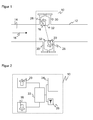
- FIG. 3 shows a further longitudinal section of a pipeline 12 with a fluid 14 flowing therein as well as a pair of ultrasonic transducers 18, 20.
- the ultrasonic signal is deviated from an ideal propagation direction on a measuring path 34 as a function of the flow velocity, as indicated by the dashed lines 36. Not only does the propagation direction of the ultrasound change, but also the shape of the sound lobe.
- tear-off vertebrae 38 form, which can also assume a much greater extent than shown. These lead to a strong signal distortion, namely a disturbing noise level to the ultrasonic transducers 18, 20, which significantly affects the quality of the speed measurement and makes a measurement of ultrasound from a certain speed of the fluid 14 in practice unsuitable.
- the flow-optimized outer contour 32 according to the invention thus makes it possible to first apply an ultrasonic measurement at flow speeds even above a limit of about 70 m / s, for example in a flare gas line.
- the Abrissturbulenzen or demolition swirls 38 but also reinforce the drift effect in addition to the disturbing noise level.
- FIG. 4 With triangular data points and a solid line, the theoretical dependence of the drift angle on the flow velocity calculated with a vector approach is plotted. Experimental studies show that the maximum amplitude of the transmitted ultrasound signal is significantly more forgiving than the theoretical derivation predicts. The curve of the actual drift angles would therefore be in FIG. 4 clearly above the illustrated theoretical prediction and a suppression of demolition vortices 38 can therefore as a second improvement effect Reducing the noise level also limits the negative effects of drift.
- FIG. 5 a further embodiment of the measuring device 10 according to the invention is shown. It differs from the measuring device according to FIG. 1 in that the ultrasonic transducers 18, 20 have a parallel offset 40 relative to each other. Thus, if the ultrasound propagated in a simple straight line 42, then the main propagation direction missed the opposite ultrasonic transducer 18, 20.
- the sound beam 36 is blown. Due to the parallel offset 40, the sound lobe emitted from the ultrasonic transducer 20 on the measurement path against the flow direction due to the drift hits the ultrasonic transducer 18 better than if no parallel offset 40 is provided. Conversely, on the measuring path with the flow direction of the adverse effect of the drift is only slightly amplified. Reason is the different temporal influence of the flow on the two opposite ultrasonic signals. In other words, the adverse effect on the measurement path with the flow direction is overcompensated by the positive effect on the measurement path against the flow direction.
- the parallel offset 40 is chosen to be so large that the signal / noise ratio is equally good on both measurement paths and thus the overall system achieves its optimum.
- FIG. 6 shows a further embodiment of the measuring device 10 according to the invention, which differs from the measuring device according to FIG. 1 differs in that in addition to a flow-optimized outer contour 32 of the ultrasonic transducer 18, 20 or from the housing 28 and the wall of the pipe 12 is optimized flow.
- deformations 44 are attached to the inner wall of the pipeline 12, which preferably continue the flow-optimized outer contour 32.
- the fluid 14 is already directed at the ultrasound transducers 18, 20 during flow, so that the demolition vortices 38 are even more strongly suppressed on the housing 28 than by the outer contour 32 alone.
- the deformations 44 make it possible to better adapt a flow-optimized contour and, in particular, provide it over a larger area than the housing 28 or the cross-section of the connecting piece 30 Incident surfaces of the incoming and outflowing fluid 14 for an additional improvement of the measurement accuracy even better to optimize the flow.
- a rectifier can be provided in the interior of the pipeline 12, which linearizes the flow of the fluid 12 for the region of the measuring device 10 or at least reduces turbulence and which is arranged in or in front of this region.
- the outer contour 32, the deformations 44 and / or the rectifier can be optimized to cooperate for the suppression of demolition swirls 38 as far as possible.
- ultrasonic transducers 18, 20 to use further individual or pairs of ultrasonic transducers in order to obtain further measuring paths.
- a particular position for such an additional ultrasound transducer is downstream in a region in which more strongly propagated signal portions are received so as to obtain better overall information by receiving the same signal at different locations.
- further pairs of ultrasonic transducers can be used in order to measure a locally different proportion of the flow velocity in the manner of a conventional multipath system.
- Each measuring path provides information about the flow velocity in its local environment. If the flow is disturbed, this need not necessarily correspond to the mean flow velocity and it may also result in an inaccurate determination of the volume flow rate. Further measurement paths across the cross-section of the pipeline 12 broaden the base of information about the flow profile and thus allow a more accurate measurement.
Priority Applications (3)
| Application Number | Priority Date | Filing Date | Title |
|---|---|---|---|
| PL08102712T PL2103912T3 (pl) | 2008-03-18 | 2008-03-18 | Pomiar przepływu za pomocą ultradźwięku |
| EP08102712.0A EP2103912B1 (fr) | 2008-03-18 | 2008-03-18 | Mesure de l'écoulement à ultrasons |
| EP20090100168 EP2103911B1 (fr) | 2008-03-18 | 2009-03-06 | Mesure de l'écoulement à ultrasons |
Applications Claiming Priority (1)
| Application Number | Priority Date | Filing Date | Title |
|---|---|---|---|
| EP08102712.0A EP2103912B1 (fr) | 2008-03-18 | 2008-03-18 | Mesure de l'écoulement à ultrasons |
Publications (2)
| Publication Number | Publication Date |
|---|---|
| EP2103912A1 true EP2103912A1 (fr) | 2009-09-23 |
| EP2103912B1 EP2103912B1 (fr) | 2016-09-07 |
Family
ID=39712670
Family Applications (2)
| Application Number | Title | Priority Date | Filing Date |
|---|---|---|---|
| EP08102712.0A Active EP2103912B1 (fr) | 2008-03-18 | 2008-03-18 | Mesure de l'écoulement à ultrasons |
| EP20090100168 Active EP2103911B1 (fr) | 2008-03-18 | 2009-03-06 | Mesure de l'écoulement à ultrasons |
Family Applications After (1)
| Application Number | Title | Priority Date | Filing Date |
|---|---|---|---|
| EP20090100168 Active EP2103911B1 (fr) | 2008-03-18 | 2009-03-06 | Mesure de l'écoulement à ultrasons |
Country Status (2)
| Country | Link |
|---|---|
| EP (2) | EP2103912B1 (fr) |
| PL (1) | PL2103912T3 (fr) |
Cited By (5)
| Publication number | Priority date | Publication date | Assignee | Title |
|---|---|---|---|---|
| DE102014106429A1 (de) | 2013-07-10 | 2015-01-15 | Sick Ag | Durchflussmessvorrichtung und Verfahren zum Messen der Strömungsgeschwindigkeit eines Fluids |
| EP3855134A1 (fr) | 2020-01-21 | 2021-07-28 | SICK Engineering GmbH | Dispositif de mesure du débit d'écoulement d'un fluide |
| DE202020104105U1 (de) | 2020-07-16 | 2021-10-20 | Sick Engineering Gmbh | Durchflussmessgerät zur Messung des Durchflusses eines Fluids |
| EP3940346A1 (fr) | 2020-07-16 | 2022-01-19 | SICK Engineering GmbH | Débitmètre et procédé de mesure du débit d'un fluide |
| CN115905961A (zh) * | 2023-03-09 | 2023-04-04 | 广东广宇科技发展有限公司 | 一种基于多源数据的管道缺陷分析方法 |
Families Citing this family (5)
| Publication number | Priority date | Publication date | Assignee | Title |
|---|---|---|---|---|
| NL2005886C2 (en) | 2010-12-21 | 2012-06-25 | Nest Internat N V | Device and method for determining a flow velocity of a fluid or a fluid component in a pipeline. |
| DE102014006743A1 (de) * | 2014-05-12 | 2015-11-12 | Wilo Se | Volumenstromsensor |
| DE102016103419A1 (de) | 2016-02-26 | 2017-08-31 | Krohne Messtechnik Gmbh | Messstab für den Nachweis eines strömenden Mediums in einem Rohr und diesbezügliche Messanordnung |
| EP3367072B1 (fr) | 2017-02-24 | 2019-01-02 | SICK Engineering GmbH | Mesure de l'écoulement à ultrasons |
| DE102018126613B4 (de) * | 2018-10-25 | 2022-08-11 | Sensus Spectrum Llc | Messvorrichtung zur Bestimmung des Durchflusses eines durch einen Rohrabschnitt hindurchströmenden Fluids |
Citations (7)
| Publication number | Priority date | Publication date | Assignee | Title |
|---|---|---|---|---|
| US5251490A (en) | 1992-02-07 | 1993-10-12 | Kronberg James W | Ultrasonic fluid flow measurement method and apparatus |
| EP0580099A2 (fr) | 1992-07-23 | 1994-01-26 | G. Kromschröder AG | Compteur de gaz à ultrasons |
| EP0622614A1 (fr) | 1993-04-27 | 1994-11-02 | NUOVOPIGNONE INDUSTRIE MECCANICHE E FONDERIA S.p.A. | Débitmètre à ultra-sons et régulateur d'écoulement |
| WO1996036852A1 (fr) | 1995-05-17 | 1996-11-21 | Schlumberger Industries S.A. | Dispositif pour la mesure de la vitesse d'ecoulement d'un fluide par ultrasons |
| US6647804B1 (en) | 1999-02-10 | 2003-11-18 | Rd Instruments, Inc. | System and method for flow measurement in a pipe |
| DE102004060118A1 (de) | 2004-12-13 | 2006-06-14 | Endress + Hauser Flowtec Ag | Vorrichtung zur Bestimmung und/oder Überwachung des Volumen- und/oder Massendurchflusses |
| DE102004060064A1 (de) | 2004-12-14 | 2006-06-29 | Robert Bosch Gmbh | Ultraschall-Durchflussmesser mit Turbulatoren |
Family Cites Families (6)
| Publication number | Priority date | Publication date | Assignee | Title |
|---|---|---|---|---|
| DE2823497C3 (de) * | 1978-05-30 | 1982-01-21 | Drägerwerk AG, 2400 Lübeck | Verfahren zur Messung der Strömungsgeschwindigkeit von Gasen oder Flüssigkeiten sowie Vorrichtung hierzu |
| US4754650A (en) | 1983-07-29 | 1988-07-05 | Panametrics, Inc. | Apparatus and methods for measuring fluid flow parameters |
| US5728948A (en) * | 1993-03-09 | 1998-03-17 | Commonwealth Scientific And Industrial Research Organisation | Fluid meter construction |
| DE19859572A1 (de) * | 1998-12-22 | 2000-06-29 | Sick Ag | Ultraschallmeßanordnung |
| DE102004060065B4 (de) * | 2004-12-14 | 2016-10-20 | Robert Bosch Gmbh | Ultraschall Durchflussmesser mit Leitelementen |
| DE102004060062A1 (de) * | 2004-12-14 | 2006-06-29 | Robert Bosch Gmbh | Ultraschallmesseinrichtung |
-
2008
- 2008-03-18 EP EP08102712.0A patent/EP2103912B1/fr active Active
- 2008-03-18 PL PL08102712T patent/PL2103912T3/pl unknown
-
2009
- 2009-03-06 EP EP20090100168 patent/EP2103911B1/fr active Active
Patent Citations (7)
| Publication number | Priority date | Publication date | Assignee | Title |
|---|---|---|---|---|
| US5251490A (en) | 1992-02-07 | 1993-10-12 | Kronberg James W | Ultrasonic fluid flow measurement method and apparatus |
| EP0580099A2 (fr) | 1992-07-23 | 1994-01-26 | G. Kromschröder AG | Compteur de gaz à ultrasons |
| EP0622614A1 (fr) | 1993-04-27 | 1994-11-02 | NUOVOPIGNONE INDUSTRIE MECCANICHE E FONDERIA S.p.A. | Débitmètre à ultra-sons et régulateur d'écoulement |
| WO1996036852A1 (fr) | 1995-05-17 | 1996-11-21 | Schlumberger Industries S.A. | Dispositif pour la mesure de la vitesse d'ecoulement d'un fluide par ultrasons |
| US6647804B1 (en) | 1999-02-10 | 2003-11-18 | Rd Instruments, Inc. | System and method for flow measurement in a pipe |
| DE102004060118A1 (de) | 2004-12-13 | 2006-06-14 | Endress + Hauser Flowtec Ag | Vorrichtung zur Bestimmung und/oder Überwachung des Volumen- und/oder Massendurchflusses |
| DE102004060064A1 (de) | 2004-12-14 | 2006-06-29 | Robert Bosch Gmbh | Ultraschall-Durchflussmesser mit Turbulatoren |
Cited By (7)
| Publication number | Priority date | Publication date | Assignee | Title |
|---|---|---|---|---|
| DE102014106429A1 (de) | 2013-07-10 | 2015-01-15 | Sick Ag | Durchflussmessvorrichtung und Verfahren zum Messen der Strömungsgeschwindigkeit eines Fluids |
| EP3855134A1 (fr) | 2020-01-21 | 2021-07-28 | SICK Engineering GmbH | Dispositif de mesure du débit d'écoulement d'un fluide |
| US11619528B2 (en) | 2020-01-21 | 2023-04-04 | Sick Engineering Gmbh | Ultrasonic flow measuring device having a wall thickness being less in the area of the phased array ultrasonic transducer contact area |
| DE202020104105U1 (de) | 2020-07-16 | 2021-10-20 | Sick Engineering Gmbh | Durchflussmessgerät zur Messung des Durchflusses eines Fluids |
| EP3940346A1 (fr) | 2020-07-16 | 2022-01-19 | SICK Engineering GmbH | Débitmètre et procédé de mesure du débit d'un fluide |
| WO2022013653A1 (fr) | 2020-07-16 | 2022-01-20 | Sick Engineering Gmbh | Débitmètre et procédé de mesure du débit d'un fluide |
| CN115905961A (zh) * | 2023-03-09 | 2023-04-04 | 广东广宇科技发展有限公司 | 一种基于多源数据的管道缺陷分析方法 |
Also Published As
| Publication number | Publication date |
|---|---|
| EP2103911A1 (fr) | 2009-09-23 |
| EP2103912B1 (fr) | 2016-09-07 |
| EP2103911B1 (fr) | 2014-09-03 |
| PL2103912T3 (pl) | 2017-02-28 |
Similar Documents
| Publication | Publication Date | Title |
|---|---|---|
| EP2103912B1 (fr) | Mesure de l'écoulement à ultrasons | |
| EP3004812B1 (fr) | Débitmètre ultrasonique | |
| EP2044392B1 (fr) | Système de mesure pour un milieu s'écoulant dans un conduit de traitement | |
| EP1831649B1 (fr) | Debitmetre a ultrasons et procede de mesure de debit par ultrasons | |
| EP2386835B1 (fr) | Mesure par ultrasons de la vitesse d'écoulement d'un fluide dans une conduite | |
| DE102013114475B4 (de) | Ultraschallmessvorrichtung und Verfahren zum Bestimmen der Strömungsgeschwindigkeit | |
| EP2710337B1 (fr) | Débitmètre à ultrasons | |
| EP2872857B1 (fr) | Débitmètre à ultrasons | |
| EP3230696B1 (fr) | Débitmètre ultrasonique | |
| EP2818874B1 (fr) | Dispositif de mesure des ultrasons | |
| EP2656017B1 (fr) | Élément de couplage d'un transducteur ultrasonique pour un débitmètre à ultrasons | |
| EP3209976B1 (fr) | Procédé de mesure de débit par ultrasons directement sur un tuyau et ensemble formant un circuit pour la commande d'une mesure de débit par ultrasons directement sur un tuyau | |
| EP2710336A1 (fr) | Débitmètre à ultrasons | |
| EP4182703A1 (fr) | Débitmètre et procédé de mesure du débit d'un fluide | |
| DE102008013224A1 (de) | Messsystem und Verfahren zur Bestimmung und/oder Überwachung eines Durchflusses eines Messmediums durch ein Messrohr | |
| EP3343185B1 (fr) | Débitmètre à ultrasons et procédé de mesure du débit | |
| EP2656018A1 (fr) | Débitmètre à ultrasons | |
| EP3273205A1 (fr) | Procede et systeme de debitmetre a ultrasons a pince et corps destine a realiser la mesure | |
| EP3748308A1 (fr) | Débitmètre à ultrasons, utilisation d'un débitmètre à ultrasons dans un organe d'arrêt et organe d'arrêt | |
| EP3855134B1 (fr) | Dispositif de mesure du débit d'écoulement d'un fluide | |
| DE4341542C2 (de) | Durchflussmessvorrichtung | |
| EP3367072A1 (fr) | Mesure de l'écoulement à ultrasons | |
| EP0504304B1 (fr) | Fluxmetre ultrasonique pour courants de gaz et de liquides | |
| EP3715797A2 (fr) | Débitmètre à ultrasons, procédé de fonctionnement d'un débitmètre à ultrasons, ensemble de mesure et procédé de fonctionnement d'un ensemble de mesure | |
| WO2005031369A2 (fr) | Capteur a ultrasons, et procede pour mesurer des vitesses d'ecoulement |
Legal Events
| Date | Code | Title | Description |
|---|---|---|---|
| PUAI | Public reference made under article 153(3) epc to a published international application that has entered the european phase |
Free format text: ORIGINAL CODE: 0009012 |
|
| 17P | Request for examination filed |
Effective date: 20081204 |
|
| AK | Designated contracting states |
Kind code of ref document: A1 Designated state(s): AT BE BG CH CY CZ DE DK EE ES FI FR GB GR HR HU IE IS IT LI LT LU LV MC MT NL NO PL PT RO SE SI SK TR |
|
| AX | Request for extension of the european patent |
Extension state: AL BA MK RS |
|
| AKX | Designation fees paid |
Designated state(s): AT BE BG CH CY CZ DE DK EE ES FI FR GB GR HR HU IE IS IT LI LT LU LV MC MT NL NO PL PT RO SE SI SK TR |
|
| 17Q | First examination report despatched |
Effective date: 20110503 |
|
| GRAP | Despatch of communication of intention to grant a patent |
Free format text: ORIGINAL CODE: EPIDOSNIGR1 |
|
| INTG | Intention to grant announced |
Effective date: 20160503 |
|
| GRAS | Grant fee paid |
Free format text: ORIGINAL CODE: EPIDOSNIGR3 |
|
| GRAA | (expected) grant |
Free format text: ORIGINAL CODE: 0009210 |
|
| AK | Designated contracting states |
Kind code of ref document: B1 Designated state(s): AT BE BG CH CY CZ DE DK EE ES FI FR GB GR HR HU IE IS IT LI LT LU LV MC MT NL NO PL PT RO SE SI SK TR |
|
| REG | Reference to a national code |
Ref country code: GB Ref legal event code: FG4D Free format text: NOT ENGLISH |
|
| REG | Reference to a national code |
Ref country code: CH Ref legal event code: EP |
|
| REG | Reference to a national code |
Ref country code: IE Ref legal event code: FG4D Free format text: LANGUAGE OF EP DOCUMENT: GERMAN |
|
| REG | Reference to a national code |
Ref country code: AT Ref legal event code: REF Ref document number: 827284 Country of ref document: AT Kind code of ref document: T Effective date: 20161015 |
|
| REG | Reference to a national code |
Ref country code: DE Ref legal event code: R096 Ref document number: 502008014604 Country of ref document: DE |
|
| REG | Reference to a national code |
Ref country code: NO Ref legal event code: T2 Effective date: 20160907 |
|
| REG | Reference to a national code |
Ref country code: LT Ref legal event code: MG4D |
|
| REG | Reference to a national code |
Ref country code: NL Ref legal event code: MP Effective date: 20160907 |
|
| PG25 | Lapsed in a contracting state [announced via postgrant information from national office to epo] |
Ref country code: LT Free format text: LAPSE BECAUSE OF FAILURE TO SUBMIT A TRANSLATION OF THE DESCRIPTION OR TO PAY THE FEE WITHIN THE PRESCRIBED TIME-LIMIT Effective date: 20160907 Ref country code: HR Free format text: LAPSE BECAUSE OF FAILURE TO SUBMIT A TRANSLATION OF THE DESCRIPTION OR TO PAY THE FEE WITHIN THE PRESCRIBED TIME-LIMIT Effective date: 20160907 Ref country code: FI Free format text: LAPSE BECAUSE OF FAILURE TO SUBMIT A TRANSLATION OF THE DESCRIPTION OR TO PAY THE FEE WITHIN THE PRESCRIBED TIME-LIMIT Effective date: 20160907 |
|
| PG25 | Lapsed in a contracting state [announced via postgrant information from national office to epo] |
Ref country code: LV Free format text: LAPSE BECAUSE OF FAILURE TO SUBMIT A TRANSLATION OF THE DESCRIPTION OR TO PAY THE FEE WITHIN THE PRESCRIBED TIME-LIMIT Effective date: 20160907 Ref country code: SE Free format text: LAPSE BECAUSE OF FAILURE TO SUBMIT A TRANSLATION OF THE DESCRIPTION OR TO PAY THE FEE WITHIN THE PRESCRIBED TIME-LIMIT Effective date: 20160907 Ref country code: GR Free format text: LAPSE BECAUSE OF FAILURE TO SUBMIT A TRANSLATION OF THE DESCRIPTION OR TO PAY THE FEE WITHIN THE PRESCRIBED TIME-LIMIT Effective date: 20161208 Ref country code: ES Free format text: LAPSE BECAUSE OF FAILURE TO SUBMIT A TRANSLATION OF THE DESCRIPTION OR TO PAY THE FEE WITHIN THE PRESCRIBED TIME-LIMIT Effective date: 20160907 Ref country code: NL Free format text: LAPSE BECAUSE OF FAILURE TO SUBMIT A TRANSLATION OF THE DESCRIPTION OR TO PAY THE FEE WITHIN THE PRESCRIBED TIME-LIMIT Effective date: 20160907 |
|
| PG25 | Lapsed in a contracting state [announced via postgrant information from national office to epo] |
Ref country code: RO Free format text: LAPSE BECAUSE OF FAILURE TO SUBMIT A TRANSLATION OF THE DESCRIPTION OR TO PAY THE FEE WITHIN THE PRESCRIBED TIME-LIMIT Effective date: 20160907 Ref country code: EE Free format text: LAPSE BECAUSE OF FAILURE TO SUBMIT A TRANSLATION OF THE DESCRIPTION OR TO PAY THE FEE WITHIN THE PRESCRIBED TIME-LIMIT Effective date: 20160907 |
|
| PG25 | Lapsed in a contracting state [announced via postgrant information from national office to epo] |
Ref country code: IS Free format text: LAPSE BECAUSE OF FAILURE TO SUBMIT A TRANSLATION OF THE DESCRIPTION OR TO PAY THE FEE WITHIN THE PRESCRIBED TIME-LIMIT Effective date: 20170107 Ref country code: BG Free format text: LAPSE BECAUSE OF FAILURE TO SUBMIT A TRANSLATION OF THE DESCRIPTION OR TO PAY THE FEE WITHIN THE PRESCRIBED TIME-LIMIT Effective date: 20161207 Ref country code: CZ Free format text: LAPSE BECAUSE OF FAILURE TO SUBMIT A TRANSLATION OF THE DESCRIPTION OR TO PAY THE FEE WITHIN THE PRESCRIBED TIME-LIMIT Effective date: 20160907 Ref country code: PT Free format text: LAPSE BECAUSE OF FAILURE TO SUBMIT A TRANSLATION OF THE DESCRIPTION OR TO PAY THE FEE WITHIN THE PRESCRIBED TIME-LIMIT Effective date: 20170109 Ref country code: SK Free format text: LAPSE BECAUSE OF FAILURE TO SUBMIT A TRANSLATION OF THE DESCRIPTION OR TO PAY THE FEE WITHIN THE PRESCRIBED TIME-LIMIT Effective date: 20160907 |
|
| REG | Reference to a national code |
Ref country code: DE Ref legal event code: R097 Ref document number: 502008014604 Country of ref document: DE |
|
| PG25 | Lapsed in a contracting state [announced via postgrant information from national office to epo] |
Ref country code: IT Free format text: LAPSE BECAUSE OF FAILURE TO SUBMIT A TRANSLATION OF THE DESCRIPTION OR TO PAY THE FEE WITHIN THE PRESCRIBED TIME-LIMIT Effective date: 20160907 |
|
| PLBE | No opposition filed within time limit |
Free format text: ORIGINAL CODE: 0009261 |
|
| STAA | Information on the status of an ep patent application or granted ep patent |
Free format text: STATUS: NO OPPOSITION FILED WITHIN TIME LIMIT |
|
| PG25 | Lapsed in a contracting state [announced via postgrant information from national office to epo] |
Ref country code: DK Free format text: LAPSE BECAUSE OF FAILURE TO SUBMIT A TRANSLATION OF THE DESCRIPTION OR TO PAY THE FEE WITHIN THE PRESCRIBED TIME-LIMIT Effective date: 20160907 |
|
| 26N | No opposition filed |
Effective date: 20170608 |
|
| PG25 | Lapsed in a contracting state [announced via postgrant information from national office to epo] |
Ref country code: SI Free format text: LAPSE BECAUSE OF FAILURE TO SUBMIT A TRANSLATION OF THE DESCRIPTION OR TO PAY THE FEE WITHIN THE PRESCRIBED TIME-LIMIT Effective date: 20160907 |
|
| REG | Reference to a national code |
Ref country code: CH Ref legal event code: PL |
|
| PG25 | Lapsed in a contracting state [announced via postgrant information from national office to epo] |
Ref country code: MC Free format text: LAPSE BECAUSE OF FAILURE TO SUBMIT A TRANSLATION OF THE DESCRIPTION OR TO PAY THE FEE WITHIN THE PRESCRIBED TIME-LIMIT Effective date: 20160907 |
|
| REG | Reference to a national code |
Ref country code: IE Ref legal event code: MM4A |
|
| REG | Reference to a national code |
Ref country code: FR Ref legal event code: ST Effective date: 20171130 |
|
| PG25 | Lapsed in a contracting state [announced via postgrant information from national office to epo] |
Ref country code: LU Free format text: LAPSE BECAUSE OF NON-PAYMENT OF DUE FEES Effective date: 20170318 Ref country code: FR Free format text: LAPSE BECAUSE OF NON-PAYMENT OF DUE FEES Effective date: 20170331 |
|
| PG25 | Lapsed in a contracting state [announced via postgrant information from national office to epo] |
Ref country code: LI Free format text: LAPSE BECAUSE OF NON-PAYMENT OF DUE FEES Effective date: 20170331 Ref country code: CH Free format text: LAPSE BECAUSE OF NON-PAYMENT OF DUE FEES Effective date: 20170331 Ref country code: IE Free format text: LAPSE BECAUSE OF NON-PAYMENT OF DUE FEES Effective date: 20170318 |
|
| REG | Reference to a national code |
Ref country code: BE Ref legal event code: MM Effective date: 20170331 |
|
| REG | Reference to a national code |
Ref country code: AT Ref legal event code: MM01 Ref document number: 827284 Country of ref document: AT Kind code of ref document: T Effective date: 20170318 |
|
| PG25 | Lapsed in a contracting state [announced via postgrant information from national office to epo] |
Ref country code: BE Free format text: LAPSE BECAUSE OF NON-PAYMENT OF DUE FEES Effective date: 20170331 |
|
| PG25 | Lapsed in a contracting state [announced via postgrant information from national office to epo] |
Ref country code: AT Free format text: LAPSE BECAUSE OF NON-PAYMENT OF DUE FEES Effective date: 20170318 |
|
| PG25 | Lapsed in a contracting state [announced via postgrant information from national office to epo] |
Ref country code: MT Free format text: LAPSE BECAUSE OF FAILURE TO SUBMIT A TRANSLATION OF THE DESCRIPTION OR TO PAY THE FEE WITHIN THE PRESCRIBED TIME-LIMIT Effective date: 20160907 |
|
| PG25 | Lapsed in a contracting state [announced via postgrant information from national office to epo] |
Ref country code: HU Free format text: LAPSE BECAUSE OF FAILURE TO SUBMIT A TRANSLATION OF THE DESCRIPTION OR TO PAY THE FEE WITHIN THE PRESCRIBED TIME-LIMIT; INVALID AB INITIO Effective date: 20080318 |
|
| PG25 | Lapsed in a contracting state [announced via postgrant information from national office to epo] |
Ref country code: CY Free format text: LAPSE BECAUSE OF NON-PAYMENT OF DUE FEES Effective date: 20160907 |
|
| PG25 | Lapsed in a contracting state [announced via postgrant information from national office to epo] |
Ref country code: TR Free format text: LAPSE BECAUSE OF FAILURE TO SUBMIT A TRANSLATION OF THE DESCRIPTION OR TO PAY THE FEE WITHIN THE PRESCRIBED TIME-LIMIT Effective date: 20160907 |
|
| PGFP | Annual fee paid to national office [announced via postgrant information from national office to epo] |
Ref country code: GB Payment date: 20220324 Year of fee payment: 15 |
|
| PGFP | Annual fee paid to national office [announced via postgrant information from national office to epo] |
Ref country code: NO Payment date: 20230321 Year of fee payment: 16 |
|
| PGFP | Annual fee paid to national office [announced via postgrant information from national office to epo] |
Ref country code: PL Payment date: 20230309 Year of fee payment: 16 |
|
| GBPC | Gb: european patent ceased through non-payment of renewal fee |
Effective date: 20230318 |
|
| PG25 | Lapsed in a contracting state [announced via postgrant information from national office to epo] |
Ref country code: GB Free format text: LAPSE BECAUSE OF NON-PAYMENT OF DUE FEES Effective date: 20230318 |
|
| PG25 | Lapsed in a contracting state [announced via postgrant information from national office to epo] |
Ref country code: GB Free format text: LAPSE BECAUSE OF NON-PAYMENT OF DUE FEES Effective date: 20230318 |
|
| PGFP | Annual fee paid to national office [announced via postgrant information from national office to epo] |
Ref country code: DE Payment date: 20240321 Year of fee payment: 17 |