EP3230696B1 - Débitmètre ultrasonique - Google Patents
Débitmètre ultrasonique Download PDFInfo
- Publication number
- EP3230696B1 EP3230696B1 EP15794854.8A EP15794854A EP3230696B1 EP 3230696 B1 EP3230696 B1 EP 3230696B1 EP 15794854 A EP15794854 A EP 15794854A EP 3230696 B1 EP3230696 B1 EP 3230696B1
- Authority
- EP
- European Patent Office
- Prior art keywords
- measuring tube
- reflector
- function
- ultrasonic
- signal path
- Prior art date
- Legal status (The legal status is an assumption and is not a legal conclusion. Google has not performed a legal analysis and makes no representation as to the accuracy of the status listed.)
- Active
Links
- 238000000034 method Methods 0.000 claims description 28
- 230000008569 process Effects 0.000 claims description 17
- 238000004519 manufacturing process Methods 0.000 claims description 15
- 239000002184 metal Substances 0.000 claims description 10
- 230000000295 complement effect Effects 0.000 claims description 5
- 230000007704 transition Effects 0.000 claims description 4
- 239000013598 vector Substances 0.000 claims description 4
- 238000007493 shaping process Methods 0.000 claims description 2
- 238000002604 ultrasonography Methods 0.000 description 22
- 238000005259 measurement Methods 0.000 description 13
- 230000008878 coupling Effects 0.000 description 12
- 238000010168 coupling process Methods 0.000 description 12
- 238000005859 coupling reaction Methods 0.000 description 12
- 238000005516 engineering process Methods 0.000 description 7
- 239000000463 material Substances 0.000 description 7
- 238000003466 welding Methods 0.000 description 5
- 230000006978 adaptation Effects 0.000 description 4
- 230000008901 benefit Effects 0.000 description 4
- 230000005540 biological transmission Effects 0.000 description 4
- 239000007788 liquid Substances 0.000 description 3
- 230000009467 reduction Effects 0.000 description 3
- 238000005266 casting Methods 0.000 description 2
- 230000008859 change Effects 0.000 description 2
- 238000006243 chemical reaction Methods 0.000 description 2
- 238000010276 construction Methods 0.000 description 2
- 238000005553 drilling Methods 0.000 description 2
- 238000011156 evaluation Methods 0.000 description 2
- 238000001000 micrograph Methods 0.000 description 2
- 238000006479 redox reaction Methods 0.000 description 2
- 230000004913 activation Effects 0.000 description 1
- 238000004026 adhesive bonding Methods 0.000 description 1
- 238000006073 displacement reaction Methods 0.000 description 1
- 230000000694 effects Effects 0.000 description 1
- 230000002349 favourable effect Effects 0.000 description 1
- 239000012530 fluid Substances 0.000 description 1
- 239000011888 foil Substances 0.000 description 1
- 238000009434 installation Methods 0.000 description 1
- 230000010354 integration Effects 0.000 description 1
- 230000003993 interaction Effects 0.000 description 1
- 239000012528 membrane Substances 0.000 description 1
- 238000000465 moulding Methods 0.000 description 1
- 230000000717 retained effect Effects 0.000 description 1
- 239000003566 sealing material Substances 0.000 description 1
- 238000005476 soldering Methods 0.000 description 1
- 239000003832 thermite Substances 0.000 description 1
Images


Classifications
-
- G—PHYSICS
- G01—MEASURING; TESTING
- G01F—MEASURING VOLUME, VOLUME FLOW, MASS FLOW OR LIQUID LEVEL; METERING BY VOLUME
- G01F1/00—Measuring the volume flow or mass flow of fluid or fluent solid material wherein the fluid passes through a meter in a continuous flow
- G01F1/66—Measuring the volume flow or mass flow of fluid or fluent solid material wherein the fluid passes through a meter in a continuous flow by measuring frequency, phase shift or propagation time of electromagnetic or other waves, e.g. using ultrasonic flowmeters
- G01F1/662—Constructional details
-
- G—PHYSICS
- G01—MEASURING; TESTING
- G01F—MEASURING VOLUME, VOLUME FLOW, MASS FLOW OR LIQUID LEVEL; METERING BY VOLUME
- G01F1/00—Measuring the volume flow or mass flow of fluid or fluent solid material wherein the fluid passes through a meter in a continuous flow
- G01F1/66—Measuring the volume flow or mass flow of fluid or fluent solid material wherein the fluid passes through a meter in a continuous flow by measuring frequency, phase shift or propagation time of electromagnetic or other waves, e.g. using ultrasonic flowmeters
- G01F1/667—Arrangements of transducers for ultrasonic flowmeters; Circuits for operating ultrasonic flowmeters
Definitions
- the present invention relates to a measuring tube designed for use in an ultrasonic flow measuring device according to the preamble of claim 1, an ultrasonic flow measuring device with a measuring tube according to claim 6 and a method for producing a measuring tube according to claim 9.
- Ultrasonic flowmeters are widely used in process and automation technology. They allow the volume flow and / or mass flow in a pipeline to be determined in a simple manner.
- the known ultrasonic flowmeters often work according to the time difference principle.
- the different transit times of ultrasonic waves in particular ultrasonic pulses, so-called bursts, are evaluated relative to the direction of flow of the liquid.
- ultrasonic pulses are sent at a certain angle to the pipe axis both with and against the flow. From the transit time difference, the flow velocity and thus the volume flow rate can be determined if the diameter of the pipe section is known.
- the ultrasonic waves are generated or received using so-called ultrasonic transducers.
- ultrasonic transducers are firmly attached in the pipe wall of the relevant pipe section.
- Clamp-on ultrasonic flowmeters are also available. In these systems, the ultrasonic transducers are pressed from outside the measuring tube onto the tube wall.
- clamp-on ultrasonic flow measurement systems is that they do not touch the measuring medium and are attached to an existing pipe.
- the ultrasonic transducers usually consist of an electromechanical transducer element, e.g. a piezoelectric element, and a coupling layer.
- the ultrasonic waves are generated as acoustic signals and guided to the pipe wall via the coupling layer and from there into the liquid, in the case of clamp-on systems, or they are coupled into the measurement medium via the coupling layer in inline systems. Then the coupling layer is also called the membrane less often.
- a further coupling layer a so-called adaptation layer, can be arranged between the piezoelectric element and the coupling layer.
- the adaptation layer takes on the function of the transmission of the ultrasound signal and at the same time the reduction of a reflection at boundary layers between two materials caused by different acoustic impedances.
- the ultrasonic transducers are arranged in a common plane on the measuring tube, either on opposite sides of the measuring tube, then the acoustic signal, projected onto a tube cross-section, runs once along a secant through the measuring tube , or on the same side of the measuring tube, then the acoustic signal is reflected on the opposite side of the measuring tube, whereby the acoustic signal twice along the measuring tube on the cross section through the measuring tube projected secant.
- the US 4,103,551 and the US 4,610,167 show ultrasonic flowmeters with reflections on reflection surfaces provided for this purpose in the measuring tube.
- Multi-path systems are now also known which have a plurality of pairs of ultrasonic transducers, each of which forms a signal path along which the acoustic signals run through the measuring tube.
- the respective signal paths and the associated ultrasound transducers lie in planes that are parallel to one another and parallel to the measuring tube axis.
- the US 4,024,760 or the US 7,706,986 show examples of such multi-path systems.
- One advantage of multi-path systems is that they measure the profile of the flow of the measuring medium in the measuring tube at several points and can therefore provide highly precise measured values for the flow. This is achieved, among other things, by weighting the individual transit times differently along the different signal paths.
- a disadvantage of multi-path systems is their manufacturing costs, since several ultrasonic transducers and possibly complex evaluation electronics are installed.
- the EP 0 715 155 A1 has a measuring arrangement with multiple refraction, the subsections of the signal path only forming a plane that runs parallel to the measuring tube axis.
- the reflection surfaces at which a first section of the signal path ends and a second section of the signal path follows are shown in FIG EP 0 715 155 A1 shown as a flat shaped body, which are attached to the inside of the tube.
- the DE 10 2008 055 030 A1 describes a connection piece formed by hydroforming in an ultrasonic flow meter.
- An ultrasonic transducer is used in this connector.
- the signal is transmitted along a straight signal path without the signal being reflected on the pipe wall.
- the measuring tube of the flow meter has a flat shape, so that - unlike round cross-sections - less disturbances in the flow profile can occur due to turbulence.
- the DE 102 49 542 A1 describes a coupling surface for coupling an ultrasonic signal from an ultrasonic transducer into a measuring tube, the coupling surface being inclined from the measuring tube is molded out.
- the measuring tube also has a shaped body 10 which provides a reflection surface.
- the EP 0 303 255 A1 describes a measuring tube of an ultrasonic flow measuring device, in which a reflection surface is formed integrally with the measuring tube. This leads to an average widening of the measuring tube over a wide range, which is unfavorable for the exact determination of the measurement data.
- a connection piece with a thread is formed in which a reflector can then be used.
- This manufacturing variant has proven itself for all measuring tubes, regardless of their nominal size. However, production requires exact adherence to the specified drilling patterns and each connection piece must be processed separately before the reflector is inserted.
- an ultrasonic flow meter which has two reflectors which are oriented in such a way that the sound waves emitted by the ultrasonic transducer are guided back to the ultrasonic transducer by the flowing fluid.
- the reflectors are incorporated into the measuring tube wall or arranged in the measuring channel in the form of reflector bodies.
- reflector bodies arranged in the measuring channel disturb the flow profile of the medium.
- the DE 10 2011 079250 A1 and the WO 02/44662 A1 each teach an ultrasonic flow meter that has reflection points in the inner wall of the measuring tube. These are either attached to the inner wall or sunk into a recess in the inner wall. They therefore have no influence on the flow profile, but cannot be fully adjusted during installation.
- the object of the invention is to provide an ultrasonic flow measuring device with a plurality of reflection surfaces in the measuring tube, the measuring tube being able to be manufactured with a reduced manufacturing time, but including the possibility of defining highly precisely aligned reflection surfaces for specifying an optimal signal path.
- the object is achieved by a measuring tube with the features of claim 1 and by an ultrasonic flow meter with the features of claim 6.
- a measuring tube according to the invention designed for use in an ultrasonic flow measuring device, comprises a measuring tube wall and at least in some areas a basic shape with a rotationally symmetrical or polygonal cross section. It has a straight measuring tube axis (M).
- the measuring tube has at least one functional surface for positioning a reflector, on which an acoustic signal is reflected on a signal path.
- a functional surface for positioning a single reflector can suffice. This enables the fine adjustment and fine alignment of the reflector and the associated reflection surface.
- a measuring tube which is analogous to DE 10 2013 105 922 A1 designed for multiple reflection, several functional surfaces and reflectors are of course necessary.
- At least one functional surface is integrally formed from the measuring tube wall. It is not cast.
- the measuring tube wall is preferably made of a metal. As is known, metal is ductile and can be deformed. As is also known, the person skilled in the art recognizes a deformation process compared to a casting on the basis of the orientation of the metal structure in the micrograph. Any functional surfaces that are subsequently welded or glued on are not based on any deformation process, as the person skilled in the art can also immediately recognize from a micrograph.
- the aforementioned functional surface is a partial spherical surface and is used to support a reflector. At least one functional surface is oriented such that a measuring tube section with at least one functional surface protrudes outwards from the basic shape of the measuring tube.
- the measuring tube has a closed measuring tube wall in the area of at least one functional surface. Avoiding holes is an important aspect of flow measurement. Each individual hole must be checked for leaks at the medium pressures. Various media can also attack the sealing material. Therefore, the measuring tube should only have a minimum of holes.
- the measuring tube has a plurality of functional surfaces for positioning one reflector each, the ultrasound signal being reflected several times on the signal path.
- the measuring tube has a metal microstructure in the transition area between the basic shape of the measuring tube wall and at least one functional surface, which metal microstructure has an orientation in the direction of the contour of the measuring tube.
- the at least one functional surface is formed from the measuring tube by an internal high-pressure forming process.
- An ultrasonic flow measuring device comprises a measuring tube according to the invention designed for use in an ultrasonic flow measuring device, a transmitter for transmitting an acoustic signal on a signal path and a receiver for receiving the acoustic signal on the signal path.
- the measuring tube according to the invention has at least one reflector, each with at least one reflection surface.
- the reflector has a connection surface which defines a segment of a circle in at least one sectional view.
- the circular segment is complementary to the circular partial surface of the functional surface of the measuring tube. That means it has approximately the same radian measure.
- the reflector is arranged on the functional surface of the measuring tube.
- the interaction of the reflectors with the functional surfaces ensures a fine adjustment of the reflective surfaces to align them with an ideal signal path.
- the measuring tube has a plurality of reflectors, the acoustic signal being reflected several times on a signal path, in particular by the acoustic signal being reflected at least once on a reflection surface of each reflector.
- the ultrasonic flow meter takes into account a rotation compensation of rotating flows.
- Such a method is simple and safe to handle in terms of production technology and, if the signal path is precisely set, can improve the manufacturing time and the quality of the measuring device.
- the reflectors prefferably be fixed by introducing a film-like intermediate layer between one of the functional surfaces of a measuring tube and a connection surface of a reflector and by reactive bonding.
- the measuring tube according to the invention can be subdivided into individual measuring tube sections or partial areas, which are welded to one another or connected to one another integrally without any seams, that is to say without welding seams.
- the latter is preferred because the seamless transitions of the measuring tube sections or partial areas can be produced particularly inexpensively and in a time-saving manner.
- an additional manufacturing step and an additional component can be saved.
- the basic shape can only be formed in sections, in particular over only one measuring tube section or a first partial region of the measuring tube, or can extend over the entire course of the measuring tube.
- Known basic shapes with a rotationally symmetrical or polygonal cross section in the area of pipe construction are, for example, cylindrical shapes or often used in gas pipes, pipes with a cuboidal lateral surface.
- the ultrasonic flow meter also has a transmitter for transmitting an acoustic signal on a signal path and a receiver for receiving the acoustic signal on the signal path.
- the terms transmitter and receiver are to be understood in the context of the present invention in such a way that the transmitter and the receiver can be set by one and the same ultrasound transducer.
- the corresponding ultrasound transducer has an operating mode for the transmission mode and functions as a transmitter in this operating mode. It also has an operating mode for the receive mode and acts as a receiver in this operating mode. After an ultrasound signal has been emitted, the ultrasound transducer can switch from the transmit mode to the receive mode while the ultrasound signal passes through a signal path in the measuring tube.
- the ultrasonic signal can be guided vertically onto a reflection surface and can be returned to the ultrasonic transducer on the signal path that has already been passed. If the ultrasound signal is fed back to the ultrasound transducer, the latter is in the receive mode and represents a receiver.
- the transmitter and the receiver are implemented in one and the same ultrasound transducer by two circuit arrangements (a circuit for the transmit mode and a circuit for the receive mode).
- an arrangement of at least two ultrasound transducers as transmitters and receivers, each of which can be switched between the transmit and receive operating modes is significantly more frequently and primarily covered by the subject matter of the invention.
- the measurement to determine the flow rate or the volume flow is carried out using the known transit time difference method.
- the measurement is preferably based on multiple reflection of the ultrasound signal in the measuring tube.
- the ultrasound signal preferably propagates in the axial direction through the measuring tube without, however, being parallel to the measuring tube axis.
- the multiple reflection has in particular the aim to compensate for measurement disturbances which are caused by the rotation of the flow.
- the measuring tube has a plurality of reflectors, on which the acoustic signal on the signal path is reflected multiple times, preferably at least once on each reflection surface.
- a large number of measuring devices are known which implement a single reflection on the measuring tube wall - a so-called two-beam arrangement.
- the present invention can also be applied to this two-beam arrangement.
- the application is particularly preferably aimed at multiple reflection, in which the ultrasonic signal is reflected several times in succession in the measuring tube on partial signal paths.
- the functional surfaces for receiving the reflectors are integrally formed from the measuring tube wall.
- integrally formed means that the functional surfaces are not welded as a separate component to or in the measuring tube but are provided by the measuring tube wall.
- the measuring tube wall is deformed in the area of the functional surfaces and deviates from its basic shape in this area.
- Integrally shaped reflection surfaces are from the DE 198 61 073 A1 or also from the US 5,090,252 A known. However, these reflective surfaces lead to a narrowing or widening of the measuring tube cross section and thus change the flow profile to a considerable extent.
- the functional surfaces can be pre-aligned and aligned such that several of the functional surfaces protrude outwards at least from the basic shape of the measuring tube. With this arrangement, optimized signal path profiles can be implemented very easily.
- the functional surfaces are molded into the measuring tube wall in such a way that multiple reflection takes place in the measuring tube, the signal path being reflected by at least three reflecting surfaces arranged one behind the other in the axial direction by reflectors.
- the reflectors arranged one behind the other can at least partially detect and compensate for a change in the flow profile which develops over the measurement range defined by the signal path.
- the ultrasound signal can deviate from the ideal point of impact on the respective reflection surface. This deviation continues on the subsequent reflection surface and, in the worst case, can lead to signal loss in the case of multiple reflections.
- This error is defined as drift in the context of the present invention.
- the reflection surface or the reflection surfaces of the reflectors are preferably convex with a reflection surface curvature.
- the tube wall of a cylindrical tube itself is also convex, the contour of the differs Reflection surface curvature in the present reflection surface from a curvature of the measuring tube wall. This difference can arise, in particular, in the different circular arc length with the circular angle remaining the same, or can result from a central angle which has a vertex which is not on the measuring tube axis.
- the at least one functional surface is advantageously formed from the measuring tube by an internal high-pressure forming process.
- the hydroforming process is also known as hydroforming.
- An outer contour is deformed by an internal pressure. Smooth rounded transitions between the measuring tube elements is an essential feature of this technique. Since the inner tube space of the measuring tube does not have any sharp edges that obstruct the flow, this technique is particularly preferred. In addition, the production time of a measuring tube is particularly short with this forming technology.
- the connecting piece can be formed from the flat functional surface using a flow drilling process.
- the connecting piece is integrally formed from the measuring tube wall by material displacement.
- a separate component for the connection piece therefore does not have to be manufactured and welded in a separate production step, which means working time and cost reduction.
- a thread can particularly preferably be formed in this connecting piece.
- the measuring tube has one or more further measuring tube sections or partial areas of the measuring tube which have a larger measuring tube cross-section than the first partial area of the measuring tube, the enlargement of these measuring tube sections being effected by an internal high-pressure forming process of the measuring tube.
- the first partial area with a smaller measuring tube cross section increases the measuring effect. This is done by increasing the flow rate and thereby increasing the ⁇ t when measuring using the transit time difference method.
- the functional surfaces are in particular molded into the measuring tube and the reflectors are aligned such that the signal path is deflected in such a way that at least three successive partial paths of the signal path each have no intersection with the measuring tube axis.
- the flow profile is recorded at different levels. Symmetrical and asymmetrical eddies in the flow profile can be better averaged out.
- Ultrasonic flowmeters such as the ultrasonic flowmeter according to the invention, are widely used in process and automation technology. They allow the volume flow and / or mass flow in a pipeline to be determined in a simple manner.
- the known ultrasonic flowmeters often work according to the transit time difference principle.
- the transit time difference principle the different transit times of ultrasonic waves, in particular ultrasonic pulses, so-called bursts, are evaluated relative to the direction of flow of the liquid.
- ultrasonic pulses are sent at a certain angle to the pipe axis both with and against the flow. From the transit time difference, the flow velocity and thus the volume flow rate can be determined if the diameter of the pipe section is known.
- the ultrasonic waves are generated or received using so-called ultrasonic transducers.
- ultrasonic transducers are firmly attached in the pipe wall of the relevant pipe section.
- Clamp-on ultrasonic flowmeters are also available.
- the ultrasonic transducers are pressed from outside the measuring tube onto the tube wall.
- it is preferably a so-called inline flow meter, in which the ultrasound transducers are firmly integrated in the measuring tube and the ultrasound signal enters the medium directly through a so-called ultrasound window from the ultrasound transducer.
- the ultrasonic transducers are usually used in the flow measuring device according to the invention. These ultrasonic transducers usually consist of an electromechanical transducer element, e.g. a piezoelectric element and a coupling layer. A further layer, a so-called adaptation layer, can be arranged between the piezoelectric element and the coupling layer.
- the adaptation layer takes on the function of the transmission of the ultrasound signal and at the same time the reduction of a reflection at boundary layers between two materials caused by different acoustic impedances. Further so-called coupling and / or matching layers, as well as metallic disks and / or layers for better temperature conduction can be provided.
- the ultrasonic transducers are arranged in a common plane on the measuring tube, either on opposite side of the measuring tube, then the acoustic signal is projected onto a tube cross-section, once along a secant through the measuring tube, or on the same side of the measuring tube, then the acoustic signal is reflected on the opposite side of the measuring tube, whereby the acoustic signal twice that Crosses measuring tube along the secant projected on the cross section through the measuring tube.
- the ultrasound signal is reflected multiple times on reflection surfaces within the measuring tube.
- the flow profile of the ultrasonic flow meter can be better captured.
- flow rotations and flow swirls can be compensated for by a particularly favorable routing of the signal path on several partial signal paths within the measuring tube.
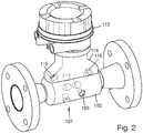
- Fig. 2 shows a structure of an ultrasonic flow meter 101, as it is already from the DE 10 2012 013 916 A1 and the DE 10 2013 105 922 A1 is known, to which reference is made in full within the scope of the present invention.
- How to get out Fig. 2 reflectors 103 are recognized in a measuring tube 102 of this ultrasonic flow meter 101. This is done by screwing the reflectors 103 into connections provided for this purpose. These screwed reflectors 103 are in Fig. 3 shown again in detail
- FIG. 1 Design variant shown in simplified form shows a Fig. 2 and 3 Modified embodiment variant according to the invention. To simplify matters, however, only a simplified section of a measuring tube 1 is shown here.
- This measuring tube 1 has a measuring tube wall 2.
- Fig. 1 shows the measuring tube wall 2 an integrally formed surface which deviates from the basic shape of the measuring tube wall, here in the form of a cylinder. This area is referred to below as functional area 4.
- a curved functional surface 4 is created instead of a flat one.
- This curved functional surface 4 is part of the measuring tube wall 2 serves to receive and guide a reflector element 3.
- a sectional view of the functional surface 4 describes a segment of a circle.
- the functional surface 4 is pressed into the measuring tube wall 2 from the inside and protrudes from the cylindrical basic shape of the measuring tube 1 on the outer circumference of the measuring tube 1.
- the shaping of the measuring tube can particularly preferably be carried out using an internal high-pressure forming process, also known as hydroforming.
- the contour of the measuring tube is deformed in some areas by an internal pressure. Since the inner tube space of the measuring tube does not have any sharp edges that obstruct the flow, this technique is particularly preferred.
- the production time of a measuring tube is particularly short with this forming technology.
- the curved functional surface primarily serves to guide and align the reflectors 3 in the measuring tube.
- a corresponding reflector 3 has a body with a partial cylinder surface, an ellipsoidal surface or, according to the invention, a partial spherical surface. This can, for example, as in Fig. 1 , shown to be connected directly to a reflection surface 5 or a separate body can be provided which is connected to the partial cylinder surface.
- the partial cylinder surface, ellipsoidal surface or spherical partial surface according to the invention assigned to the reflector preferably lies positively on the partial cylindrical surface, ellipsoidal surface or partial spherical surface according to the invention of the functional surface of the measuring tube wall.
- either the reflector or the functional surface may have webs and / or projections, the distal ends of which all end in at least one sectional view on the same circular segment.
- the reflector can then be aligned in the interior of the measuring tube in order to achieve the optimal sound path and then fixed on the measuring tube wall.
- Different technologies e.g. Gluing or soldering are used.
- welding the reflector to the measuring tube is particularly ideal, particularly in the area of the circle segment.
- the intermediate layer can particularly preferably also be a metal foil which, as a redox reaction, enables a material bond between the reflector and the measuring tube wall.
- a possible redox reaction is the thermite reaction.
- the reflectors can preferably be positioned and aligned using tools and tools and the angle can be preset.
- Fixation can then take place, for example, by means of a current surge.
- the particular advantage of this type of attachment is that the measuring tube does not require an opening for fixing at the location of the reflectors, and the measuring tube is therefore retained as a closed unit.
Landscapes
- Physics & Mathematics (AREA)
- Electromagnetism (AREA)
- Fluid Mechanics (AREA)
- General Physics & Mathematics (AREA)
- Measuring Volume Flow (AREA)
Claims (10)
- Tube de mesure (1) destiné à une utilisation dans un débitmètre à ultrasons,
lequel tube de mesure (1) présente une paroi de tube de mesure (2) et
lequel tube de mesure (1) présente au moins partiellement une forme de base avec une section à symétrie de révolution ou polygonale et un axe de tube de mesure droit,
le tube de mesure (1) présentant au moins une surface fonctionnelle (4) pour la réflexion d'un signal acoustique sur un trajet de signal, et
l'au moins une surface fonctionnelle (4) étant formée intégralement sur la paroi de tube de mesure (2)
caractérisé
en ce que l'au moins une surface fonctionnelle (4) est une surface partielle de sphère, laquelle est prévue pour le positionnement d'un réflecteur (3) et sert de support au réflecteur (3),
l'au moins une surface fonctionnelle (4) étant alignée de telle sorte qu'une partie du tube de mesure avec l'au moins une surface fonctionnelle (4) dépasse de la forme de base du tube de mesure vers l'extérieur. - Tube de mesure selon la revendication 1, caractérisé en ce que le tube de mesure (2) présente dans la zone de l'au moins une surface fonctionnelle (4) une paroi de tube de mesure (2) fermée.
- Tube de mesure selon la revendication 1 ou 2, caractérisé en ce que le tube de mesure (1) présente plusieurs surfaces fonctionnelles (4) pour le positionnement de chaque réflecteur (3), le signal ultrasonore étant réfléchi plusieurs fois sur le trajet de signal.
- Tube de mesure selon l'une des revendications précédentes, caractérisé en ce que le tube de mesure (1) présente, dans la zone de transition entre la forme de base de la paroi de tube de mesure (2) et l'au moins une surface fonctionnelle (4) une structure métallique, laquelle structure métallique présente une orientation dans la direction de l'extension du contour du tube de mesure (1).
- Tube de mesure selon l'une des revendications précédentes, caractérisé en ce que la paroi de tube de mesure (2) est constituée d'une tôle métallique, de préférence avec une épaisseur de tôle de 1 à 5 mm.
- Débitmètre à ultrasons, avec
un tube de mesure (1) selon l'une des revendications précédentes, comprenant un émetteur destiné à l'émission d'un signal acoustique sur un trajet de signal et un récepteur destiné à la réception du signal acoustique sur le trajet de signal,
le tube de mesure (1) comportant au moins un réflecteur (3) avec chacun au moins une surface de réflexion (5) et
le réflecteur (3) présentant une surface de liaison (4), laquelle définit au moins dans une vue en coupe un segment de cercle, lequel segment de cercle est complémentaire à la surface partielle de sphère de l'au moins une surface fonctionnelle (4) du tube de mesure (1) et
le réflecteur (3) étant disposé sur l'au moins une surface fonctionnelle (4) du tube de mesure (1). - Débitmètre à ultrasons selon la revendication 6, caractérisé en ce que le tube de mesure (1) comporte plusieurs réflecteurs (3), le signal acoustique étant réfléchi plusieurs fois sur le trajet du signal, notamment en ce que le signal acoustique est réfléchi au moins une fois sur une surface de réflexion (5) de chacun des réflecteurs (3).
- Débitmètre à ultrasons selon l'une des revendications précédentes 6 ou 7, caractérisé en ce que le trajet de signal se compose de segments droits, caractérisé en ce quea) les distances minimales respectives d'au moins trois segments présentent une valeur de 0,4 à 0,6 r par rapport à l'axe de tube de mesure, r étant le rayon intérieur du tube de mesure (1) ;b) un premier segment, lequel définit un premier plan parallèle à l'axe, comportant un deuxième segment directement correspondant, lequel deuxième segment définit un deuxième plan parallèle à l'axe, les deux plans passant par une surface de réflexion d'un premier réflecteur et les vecteurs normaux définissant un angle de moins de 10°,c) un troisième segment, lequel définit un troisième plan parallèle à l'axe, comportant un quatrième segment directement correspondant, lequel quatrième segment définit un quatrième plan parallèle à l'axe,les deux plans passant à travers un deuxième réflecteur avec une surface de réflexion et les vecteurs normaux définissant un angle de moins de 10°.
- Procédé destiné à la fabrication d'un tube de mesure exécuté en vue d'une utilisation dans un débitmètre selon l'une des revendications 1 à 5, la fabrication comprenant au moins les étapes suivantes :a. Formage d'un tube de mesure (2) par un procédé de formage à haute pression interne, avec l'introduction de plusieurs surfaces fonctionnelles (4), parmi lesquelles chacune des surfaces fonctionnelles (4) décrit une surface partielle de sphère ;b. Positionnement de réflecteurs (3) sur les surfaces fonctionnelles (4), pour lesquelles chaque réflecteur (3) présente une surface de liaison complémentaire à la surface fonctionnelle (4), le positionnement intervenant de préférence de telle sorte à obtenir une complémentarité de forme entre la paroi de tube de mesure (2) et le réflecteur (3),c. Alignement des réflecteurs (3) afin de régler un trajet de signal ultrasonore prédéfini, etd. Fixation des réflecteurs (3) sur la paroi de tube de mesure (2).
- Procédé selon la revendication 9, caractérisé en ce que la fixation des réflecteurs (3) est réalisée par l'application d'une couche intermédiaire en forme de film entre l'une des surfaces fonctionnelles (4) d'un tube de mesure (1) et une surface de liaison d'un réflecteur (3) et par liaison réactive.
Applications Claiming Priority (2)
| Application Number | Priority Date | Filing Date | Title |
|---|---|---|---|
| DE102014118187.5A DE102014118187A1 (de) | 2014-12-09 | 2014-12-09 | Ultraschall-Durchflussmessgerät |
| PCT/EP2015/075527 WO2016091477A1 (fr) | 2014-12-09 | 2015-11-03 | Débitmètre à ultrasons |
Publications (2)
| Publication Number | Publication Date |
|---|---|
| EP3230696A1 EP3230696A1 (fr) | 2017-10-18 |
| EP3230696B1 true EP3230696B1 (fr) | 2020-02-05 |
Family
ID=54545092
Family Applications (1)
| Application Number | Title | Priority Date | Filing Date |
|---|---|---|---|
| EP15794854.8A Active EP3230696B1 (fr) | 2014-12-09 | 2015-11-03 | Débitmètre ultrasonique |
Country Status (5)
| Country | Link |
|---|---|
| US (1) | US10634531B2 (fr) |
| EP (1) | EP3230696B1 (fr) |
| CN (1) | CN107110680B (fr) |
| DE (1) | DE102014118187A1 (fr) |
| WO (1) | WO2016091477A1 (fr) |
Families Citing this family (9)
| Publication number | Priority date | Publication date | Assignee | Title |
|---|---|---|---|---|
| US20150315666A1 (en) * | 2014-04-30 | 2015-11-05 | Ford Global Technologies, Llc | Induction annealing as a method for expanded hydroformed tube formability |
| DE102014118187A1 (de) | 2014-12-09 | 2016-06-09 | Endress + Hauser Flowtec Ag | Ultraschall-Durchflussmessgerät |
| FI129728B (fi) * | 2016-06-27 | 2022-08-15 | Flaekt Woods Ab | Laitteisto ja menetelmä ilmanvirtauksen mittaukseen |
| DE102017110308A1 (de) | 2017-05-12 | 2018-11-15 | Krohne Ag | Ultraschalldurchflussmessgerät |
| WO2019030229A1 (fr) * | 2017-08-08 | 2019-02-14 | Gwf Messsysteme Ag | Débitmètre et canal de mesure |
| CN111670342B (zh) * | 2017-12-03 | 2023-11-24 | 尤金·菲力 | 流量计 |
| EP3537112A1 (fr) * | 2018-03-08 | 2019-09-11 | Energoflow AG | Débitmètre d'écoulement fluide |
| JP6894863B2 (ja) * | 2018-03-14 | 2021-06-30 | 株式会社キーエンス | クランプオン式超音波流量センサ |
| CN113295222A (zh) * | 2020-02-21 | 2021-08-24 | 北京昌民技术有限公司 | 超声波流量计 |
Citations (1)
| Publication number | Priority date | Publication date | Assignee | Title |
|---|---|---|---|---|
| US20140083202A1 (en) * | 2011-05-17 | 2014-03-27 | Endress + Hauser Flowtec Ag | Ultrasonic, Flow Measuring Device |
Family Cites Families (28)
| Publication number | Priority date | Publication date | Assignee | Title |
|---|---|---|---|---|
| US4024760A (en) | 1975-07-25 | 1977-05-24 | Westinghouse Electric Corporation | Fluid flow measurement apparatus |
| US4103551A (en) | 1977-01-31 | 1978-08-01 | Panametrics, Inc. | Ultrasonic measuring system for differing flow conditions |
| US4610167A (en) | 1984-07-23 | 1986-09-09 | Westinghouse Electric Corp. | Apparatus for measuring flow velocity of fluids |
| WO1989001609A1 (fr) | 1987-08-10 | 1989-02-23 | Siemens Aktiengesellschaft | Installation de mesure de debit aux ultra-sons |
| DE8904673U1 (de) | 1989-04-13 | 1989-06-08 | Siemens AG, 1000 Berlin und 8000 München | Durchflußmeßeinrichtung für flüssige Medien nach dem Ultraschall-Laufzeitprinzip |
| EP0392294A1 (fr) * | 1989-04-13 | 1990-10-17 | Siemens Aktiengesellschaft | Dispositif de mesure de débit de milieux fluides fonctionnant selon le principe de la mesure de parcours d'ultrasons |
| DK0715155T3 (da) | 1994-12-02 | 2001-08-13 | Siemens Ag | Ultralyd-flowmåleindretning |
| DK171569B1 (da) * | 1995-01-31 | 1997-01-13 | Danfoss As | Ultralydsflowmåler "W" |
| DE19861075C2 (de) | 1998-03-02 | 2001-11-29 | Schubert & Salzer Control Syst | Durchflussmessvorrichtung |
| DE19808701C2 (de) * | 1998-03-02 | 2000-01-20 | Georg F Wagner | Durchflussmessvorrichtung |
| EP1337810B1 (fr) * | 2000-11-30 | 2007-01-10 | Landis+Gyr GmbH | Debitmetre par ultrasons |
| DE10249542A1 (de) | 2002-10-23 | 2004-05-06 | Endress + Hauser Flowtec Ag, Reinach | Vorrichtung zur Bestimmung und/oder Überwachung des Volumen- und/oder Massenstroms eines Mediums |
| US20040129088A1 (en) * | 2002-12-30 | 2004-07-08 | D.C. Tigwell & Associates | Single-body dual-chip orthogonal sensing transit-time flow device using a parabolic reflecting surface |
| JP2004219290A (ja) * | 2003-01-16 | 2004-08-05 | Nissan Motor Co Ltd | 超音波流量計 |
| DE10344893A1 (de) * | 2003-09-26 | 2005-04-21 | Bosch Gmbh Robert | Ultraschallsensor und Verfahren zur Messung von Strömungsgeschwindigkeiten |
| DE10361763A1 (de) * | 2003-12-29 | 2005-07-28 | Robert Bosch Gmbh | Ultraschallströmungssensor mit verschränkten Sende- und Empfangselementen |
| DE102004053673A1 (de) | 2004-11-03 | 2006-05-04 | Endress + Hauser Flowtec Ag | Vorrichtung zur Bestimmung und/oder Überwachung des Volumen- und/oder Massendurchflusses eines Mediums |
| DE102004060063B4 (de) | 2004-12-14 | 2016-10-20 | Robert Bosch Gmbh | Einrichtung zur Strömungsmessung mittels Ultraschall |
| DE102005022048A1 (de) | 2005-05-09 | 2006-11-16 | Endress + Hauser Flowtec Ag | Vorrichtung zur Bestimmung und/oder Überwachung des Volumen- und/oder Massendurchflusses eines Messmediums |
| GB0816823D0 (en) * | 2008-09-13 | 2008-10-22 | Cxr Ltd | X-ray tubes |
| DE102008055030A1 (de) | 2008-12-19 | 2010-07-01 | Endress + Hauser Flowtec Ag | Messrohr eines Ultraschall-Durchfluss-Messsystems |
| CN102288328A (zh) * | 2011-05-12 | 2011-12-21 | 铜陵德瑞曼电子科技有限公司 | 一种超声波热量表基管 |
| DE102011079250A1 (de) | 2011-07-15 | 2013-01-17 | Endress + Hauser Flowtec Ag | Ultraschall-Durchflussmessgerät |
| DE102012101098A1 (de) * | 2012-02-10 | 2013-08-14 | Endress + Hauser Flowtec Ag | Ultraschall-Durchflussmessgerät und Verfahren zur Ermittlung der Fließgeschwindigkeit bzw. des Volumendurchflusses eines Fluids |
| DE102012013916A1 (de) | 2012-07-16 | 2014-01-16 | Endress + Hauser Flowtec Ag | Ultraschall-Durchflussmessgerät |
| DE102013105407A1 (de) | 2013-05-27 | 2014-11-27 | Endress + Hauser Flowtec Ag | Vorrichtung zur Bestimmung und/oder Überwachung des Volumen- und/oder Massedurchflusses eines Mediums |
| DE102013105922A1 (de) | 2013-06-07 | 2014-12-11 | Endress + Hauser Flowtec Ag | Ultraschall-Durchflussmessgerät |
| DE102014118187A1 (de) | 2014-12-09 | 2016-06-09 | Endress + Hauser Flowtec Ag | Ultraschall-Durchflussmessgerät |
-
2014
- 2014-12-09 DE DE102014118187.5A patent/DE102014118187A1/de not_active Withdrawn
-
2015
- 2015-11-03 US US15/528,903 patent/US10634531B2/en active Active
- 2015-11-03 WO PCT/EP2015/075527 patent/WO2016091477A1/fr active Application Filing
- 2015-11-03 EP EP15794854.8A patent/EP3230696B1/fr active Active
- 2015-11-03 CN CN201580067482.5A patent/CN107110680B/zh active Active
Patent Citations (1)
| Publication number | Priority date | Publication date | Assignee | Title |
|---|---|---|---|---|
| US20140083202A1 (en) * | 2011-05-17 | 2014-03-27 | Endress + Hauser Flowtec Ag | Ultrasonic, Flow Measuring Device |
Also Published As
| Publication number | Publication date |
|---|---|
| WO2016091477A1 (fr) | 2016-06-16 |
| CN107110680B (zh) | 2020-10-23 |
| CN107110680A (zh) | 2017-08-29 |
| US10634531B2 (en) | 2020-04-28 |
| EP3230696A1 (fr) | 2017-10-18 |
| US20170314977A1 (en) | 2017-11-02 |
| DE102014118187A1 (de) | 2016-06-09 |
Similar Documents
| Publication | Publication Date | Title |
|---|---|---|
| EP3230696B1 (fr) | Débitmètre ultrasonique | |
| EP3004812B1 (fr) | Débitmètre ultrasonique | |
| EP2732248B1 (fr) | Débitmètre à ultrasons | |
| EP2172657B1 (fr) | Guide d'écoulement pour un appareil de mesure du débit, notamment un appareil de mesure à ultrasons | |
| EP1975575B1 (fr) | Débitmètre | |
| DE2458901C3 (de) | Strömungsmesser | |
| EP2386835B1 (fr) | Mesure par ultrasons de la vitesse d'écoulement d'un fluide dans une conduite | |
| EP2370795B1 (fr) | Système de mesure pour déterminer et/ou surveiller par ultrasons le débit d'un milieu de mesure dans le tube de mesure | |
| EP2103911B1 (fr) | Mesure de l'écoulement à ultrasons | |
| DE102014107697A1 (de) | Ultraschallströmungsmesser | |
| EP2710336B1 (fr) | Débitmètre à ultrasons | |
| EP2306160A1 (fr) | Organe de mesure et compteur de débit | |
| DE102012013916A1 (de) | Ultraschall-Durchflussmessgerät | |
| DE102008029772A1 (de) | Verfahren und Messsystem zur Bestimmung und/oder Überwachung des Durchflusses eines Messmediums durch ein Messrohr | |
| EP1993742A2 (fr) | Dispositif pour déterminer et/ou surveiller le débit volumique ou massique d'une substance dans une conduite tubulaire | |
| DE10254053B4 (de) | Verfahren und Vorrichtung zur Bestimmung und/oder Überwachung eines Volumen- und/oder Massenstroms | |
| DE102006038620A1 (de) | Durchflussmesser | |
| WO2012156197A1 (fr) | Débitmètre à ultrasons | |
| DE102008013224A1 (de) | Messsystem und Verfahren zur Bestimmung und/oder Überwachung eines Durchflusses eines Messmediums durch ein Messrohr | |
| WO2013117457A1 (fr) | Débitmètre à ultrasons et procédé destinés à déterminer la vitesse d'écoulement ou encore le débit volumique d'un fluide | |
| EP2898239A2 (fr) | Robinet de régulation de canalisation | |
| EP2179253A1 (fr) | Element de couplage pour debitmetre a ultrasons | |
| DE102010063789A1 (de) | Ultraschall-Durchflussmessgerät | |
| DE19503714A1 (de) | Anordnung zur Bestimmung der Strömungsgeschwindigkeit eines Fluides in Rohren mit kreisförmigem Querschnitt mittels Ultraschall | |
| EP3612802B1 (fr) | Débitmètre du type ultrasonore |
Legal Events
| Date | Code | Title | Description |
|---|---|---|---|
| STAA | Information on the status of an ep patent application or granted ep patent |
Free format text: STATUS: THE INTERNATIONAL PUBLICATION HAS BEEN MADE |
|
| PUAI | Public reference made under article 153(3) epc to a published international application that has entered the european phase |
Free format text: ORIGINAL CODE: 0009012 |
|
| STAA | Information on the status of an ep patent application or granted ep patent |
Free format text: STATUS: REQUEST FOR EXAMINATION WAS MADE |
|
| 17P | Request for examination filed |
Effective date: 20170517 |
|
| AK | Designated contracting states |
Kind code of ref document: A1 Designated state(s): AL AT BE BG CH CY CZ DE DK EE ES FI FR GB GR HR HU IE IS IT LI LT LU LV MC MK MT NL NO PL PT RO RS SE SI SK SM TR |
|
| AX | Request for extension of the european patent |
Extension state: BA ME |
|
| DAV | Request for validation of the european patent (deleted) | ||
| DAX | Request for extension of the european patent (deleted) | ||
| STAA | Information on the status of an ep patent application or granted ep patent |
Free format text: STATUS: EXAMINATION IS IN PROGRESS |
|
| 17Q | First examination report despatched |
Effective date: 20180709 |
|
| GRAP | Despatch of communication of intention to grant a patent |
Free format text: ORIGINAL CODE: EPIDOSNIGR1 |
|
| STAA | Information on the status of an ep patent application or granted ep patent |
Free format text: STATUS: GRANT OF PATENT IS INTENDED |
|
| INTG | Intention to grant announced |
Effective date: 20190917 |
|
| GRAS | Grant fee paid |
Free format text: ORIGINAL CODE: EPIDOSNIGR3 |
|
| GRAA | (expected) grant |
Free format text: ORIGINAL CODE: 0009210 |
|
| STAA | Information on the status of an ep patent application or granted ep patent |
Free format text: STATUS: THE PATENT HAS BEEN GRANTED |
|
| AK | Designated contracting states |
Kind code of ref document: B1 Designated state(s): AL AT BE BG CH CY CZ DE DK EE ES FI FR GB GR HR HU IE IS IT LI LT LU LV MC MK MT NL NO PL PT RO RS SE SI SK SM TR |
|
| REG | Reference to a national code |
Ref country code: GB Ref legal event code: FG4D Free format text: NOT ENGLISH |
|
| REG | Reference to a national code |
Ref country code: AT Ref legal event code: REF Ref document number: 1230245 Country of ref document: AT Kind code of ref document: T Effective date: 20200215 |
|
| REG | Reference to a national code |
Ref country code: DE Ref legal event code: R096 Ref document number: 502015011646 Country of ref document: DE |
|
| REG | Reference to a national code |
Ref country code: IE Ref legal event code: FG4D Free format text: LANGUAGE OF EP DOCUMENT: GERMAN |
|
| REG | Reference to a national code |
Ref country code: CH Ref legal event code: EP |
|
| REG | Reference to a national code |
Ref country code: NL Ref legal event code: MP Effective date: 20200205 |
|
| PG25 | Lapsed in a contracting state [announced via postgrant information from national office to epo] |
Ref country code: NO Free format text: LAPSE BECAUSE OF FAILURE TO SUBMIT A TRANSLATION OF THE DESCRIPTION OR TO PAY THE FEE WITHIN THE PRESCRIBED TIME-LIMIT Effective date: 20200505 Ref country code: PT Free format text: LAPSE BECAUSE OF FAILURE TO SUBMIT A TRANSLATION OF THE DESCRIPTION OR TO PAY THE FEE WITHIN THE PRESCRIBED TIME-LIMIT Effective date: 20200628 Ref country code: RS Free format text: LAPSE BECAUSE OF FAILURE TO SUBMIT A TRANSLATION OF THE DESCRIPTION OR TO PAY THE FEE WITHIN THE PRESCRIBED TIME-LIMIT Effective date: 20200205 Ref country code: FI Free format text: LAPSE BECAUSE OF FAILURE TO SUBMIT A TRANSLATION OF THE DESCRIPTION OR TO PAY THE FEE WITHIN THE PRESCRIBED TIME-LIMIT Effective date: 20200205 |
|
| REG | Reference to a national code |
Ref country code: LT Ref legal event code: MG4D |
|
| PG25 | Lapsed in a contracting state [announced via postgrant information from national office to epo] |
Ref country code: GR Free format text: LAPSE BECAUSE OF FAILURE TO SUBMIT A TRANSLATION OF THE DESCRIPTION OR TO PAY THE FEE WITHIN THE PRESCRIBED TIME-LIMIT Effective date: 20200506 Ref country code: HR Free format text: LAPSE BECAUSE OF FAILURE TO SUBMIT A TRANSLATION OF THE DESCRIPTION OR TO PAY THE FEE WITHIN THE PRESCRIBED TIME-LIMIT Effective date: 20200205 Ref country code: BG Free format text: LAPSE BECAUSE OF FAILURE TO SUBMIT A TRANSLATION OF THE DESCRIPTION OR TO PAY THE FEE WITHIN THE PRESCRIBED TIME-LIMIT Effective date: 20200505 Ref country code: LV Free format text: LAPSE BECAUSE OF FAILURE TO SUBMIT A TRANSLATION OF THE DESCRIPTION OR TO PAY THE FEE WITHIN THE PRESCRIBED TIME-LIMIT Effective date: 20200205 Ref country code: IS Free format text: LAPSE BECAUSE OF FAILURE TO SUBMIT A TRANSLATION OF THE DESCRIPTION OR TO PAY THE FEE WITHIN THE PRESCRIBED TIME-LIMIT Effective date: 20200605 Ref country code: SE Free format text: LAPSE BECAUSE OF FAILURE TO SUBMIT A TRANSLATION OF THE DESCRIPTION OR TO PAY THE FEE WITHIN THE PRESCRIBED TIME-LIMIT Effective date: 20200205 |
|
| PG25 | Lapsed in a contracting state [announced via postgrant information from national office to epo] |
Ref country code: NL Free format text: LAPSE BECAUSE OF FAILURE TO SUBMIT A TRANSLATION OF THE DESCRIPTION OR TO PAY THE FEE WITHIN THE PRESCRIBED TIME-LIMIT Effective date: 20200205 |
|
| PG25 | Lapsed in a contracting state [announced via postgrant information from national office to epo] |
Ref country code: CZ Free format text: LAPSE BECAUSE OF FAILURE TO SUBMIT A TRANSLATION OF THE DESCRIPTION OR TO PAY THE FEE WITHIN THE PRESCRIBED TIME-LIMIT Effective date: 20200205 Ref country code: RO Free format text: LAPSE BECAUSE OF FAILURE TO SUBMIT A TRANSLATION OF THE DESCRIPTION OR TO PAY THE FEE WITHIN THE PRESCRIBED TIME-LIMIT Effective date: 20200205 Ref country code: ES Free format text: LAPSE BECAUSE OF FAILURE TO SUBMIT A TRANSLATION OF THE DESCRIPTION OR TO PAY THE FEE WITHIN THE PRESCRIBED TIME-LIMIT Effective date: 20200205 Ref country code: SK Free format text: LAPSE BECAUSE OF FAILURE TO SUBMIT A TRANSLATION OF THE DESCRIPTION OR TO PAY THE FEE WITHIN THE PRESCRIBED TIME-LIMIT Effective date: 20200205 Ref country code: DK Free format text: LAPSE BECAUSE OF FAILURE TO SUBMIT A TRANSLATION OF THE DESCRIPTION OR TO PAY THE FEE WITHIN THE PRESCRIBED TIME-LIMIT Effective date: 20200205 Ref country code: LT Free format text: LAPSE BECAUSE OF FAILURE TO SUBMIT A TRANSLATION OF THE DESCRIPTION OR TO PAY THE FEE WITHIN THE PRESCRIBED TIME-LIMIT Effective date: 20200205 Ref country code: SM Free format text: LAPSE BECAUSE OF FAILURE TO SUBMIT A TRANSLATION OF THE DESCRIPTION OR TO PAY THE FEE WITHIN THE PRESCRIBED TIME-LIMIT Effective date: 20200205 Ref country code: EE Free format text: LAPSE BECAUSE OF FAILURE TO SUBMIT A TRANSLATION OF THE DESCRIPTION OR TO PAY THE FEE WITHIN THE PRESCRIBED TIME-LIMIT Effective date: 20200205 |
|
| REG | Reference to a national code |
Ref country code: DE Ref legal event code: R097 Ref document number: 502015011646 Country of ref document: DE |
|
| PLBE | No opposition filed within time limit |
Free format text: ORIGINAL CODE: 0009261 |
|
| STAA | Information on the status of an ep patent application or granted ep patent |
Free format text: STATUS: NO OPPOSITION FILED WITHIN TIME LIMIT |
|
| 26N | No opposition filed |
Effective date: 20201106 |
|
| PG25 | Lapsed in a contracting state [announced via postgrant information from national office to epo] |
Ref country code: IT Free format text: LAPSE BECAUSE OF FAILURE TO SUBMIT A TRANSLATION OF THE DESCRIPTION OR TO PAY THE FEE WITHIN THE PRESCRIBED TIME-LIMIT Effective date: 20200205 |
|
| PG25 | Lapsed in a contracting state [announced via postgrant information from national office to epo] |
Ref country code: PL Free format text: LAPSE BECAUSE OF FAILURE TO SUBMIT A TRANSLATION OF THE DESCRIPTION OR TO PAY THE FEE WITHIN THE PRESCRIBED TIME-LIMIT Effective date: 20200205 Ref country code: SI Free format text: LAPSE BECAUSE OF FAILURE TO SUBMIT A TRANSLATION OF THE DESCRIPTION OR TO PAY THE FEE WITHIN THE PRESCRIBED TIME-LIMIT Effective date: 20200205 |
|
| PG25 | Lapsed in a contracting state [announced via postgrant information from national office to epo] |
Ref country code: MC Free format text: LAPSE BECAUSE OF FAILURE TO SUBMIT A TRANSLATION OF THE DESCRIPTION OR TO PAY THE FEE WITHIN THE PRESCRIBED TIME-LIMIT Effective date: 20200205 |
|
| REG | Reference to a national code |
Ref country code: CH Ref legal event code: PL |
|
| GBPC | Gb: european patent ceased through non-payment of renewal fee |
Effective date: 20201103 |
|
| PG25 | Lapsed in a contracting state [announced via postgrant information from national office to epo] |
Ref country code: LU Free format text: LAPSE BECAUSE OF NON-PAYMENT OF DUE FEES Effective date: 20201103 |
|
| REG | Reference to a national code |
Ref country code: BE Ref legal event code: MM Effective date: 20201130 |
|
| PG25 | Lapsed in a contracting state [announced via postgrant information from national office to epo] |
Ref country code: LI Free format text: LAPSE BECAUSE OF NON-PAYMENT OF DUE FEES Effective date: 20201130 Ref country code: CH Free format text: LAPSE BECAUSE OF NON-PAYMENT OF DUE FEES Effective date: 20201130 |
|
| PG25 | Lapsed in a contracting state [announced via postgrant information from national office to epo] |
Ref country code: FR Free format text: LAPSE BECAUSE OF NON-PAYMENT OF DUE FEES Effective date: 20201130 Ref country code: IE Free format text: LAPSE BECAUSE OF NON-PAYMENT OF DUE FEES Effective date: 20201103 |
|
| PG25 | Lapsed in a contracting state [announced via postgrant information from national office to epo] |
Ref country code: GB Free format text: LAPSE BECAUSE OF NON-PAYMENT OF DUE FEES Effective date: 20201103 |
|
| REG | Reference to a national code |
Ref country code: AT Ref legal event code: MM01 Ref document number: 1230245 Country of ref document: AT Kind code of ref document: T Effective date: 20201103 |
|
| PG25 | Lapsed in a contracting state [announced via postgrant information from national office to epo] |
Ref country code: AT Free format text: LAPSE BECAUSE OF NON-PAYMENT OF DUE FEES Effective date: 20201103 |
|
| PG25 | Lapsed in a contracting state [announced via postgrant information from national office to epo] |
Ref country code: TR Free format text: LAPSE BECAUSE OF FAILURE TO SUBMIT A TRANSLATION OF THE DESCRIPTION OR TO PAY THE FEE WITHIN THE PRESCRIBED TIME-LIMIT Effective date: 20200205 Ref country code: MT Free format text: LAPSE BECAUSE OF FAILURE TO SUBMIT A TRANSLATION OF THE DESCRIPTION OR TO PAY THE FEE WITHIN THE PRESCRIBED TIME-LIMIT Effective date: 20200205 Ref country code: CY Free format text: LAPSE BECAUSE OF FAILURE TO SUBMIT A TRANSLATION OF THE DESCRIPTION OR TO PAY THE FEE WITHIN THE PRESCRIBED TIME-LIMIT Effective date: 20200205 |
|
| PG25 | Lapsed in a contracting state [announced via postgrant information from national office to epo] |
Ref country code: MK Free format text: LAPSE BECAUSE OF FAILURE TO SUBMIT A TRANSLATION OF THE DESCRIPTION OR TO PAY THE FEE WITHIN THE PRESCRIBED TIME-LIMIT Effective date: 20200205 Ref country code: AL Free format text: LAPSE BECAUSE OF FAILURE TO SUBMIT A TRANSLATION OF THE DESCRIPTION OR TO PAY THE FEE WITHIN THE PRESCRIBED TIME-LIMIT Effective date: 20200205 |
|
| PG25 | Lapsed in a contracting state [announced via postgrant information from national office to epo] |
Ref country code: BE Free format text: LAPSE BECAUSE OF NON-PAYMENT OF DUE FEES Effective date: 20201130 |
|
| P01 | Opt-out of the competence of the unified patent court (upc) registered |
Effective date: 20230601 |
|
| PGFP | Annual fee paid to national office [announced via postgrant information from national office to epo] |
Ref country code: DE Payment date: 20231121 Year of fee payment: 9 |