EP3230696B1 - Ultrasonic flow meter - Google Patents
Ultrasonic flow meter Download PDFInfo
- Publication number
- EP3230696B1 EP3230696B1 EP15794854.8A EP15794854A EP3230696B1 EP 3230696 B1 EP3230696 B1 EP 3230696B1 EP 15794854 A EP15794854 A EP 15794854A EP 3230696 B1 EP3230696 B1 EP 3230696B1
- Authority
- EP
- European Patent Office
- Prior art keywords
- measuring tube
- reflector
- function
- ultrasonic
- signal path
- Prior art date
- Legal status (The legal status is an assumption and is not a legal conclusion. Google has not performed a legal analysis and makes no representation as to the accuracy of the status listed.)
- Active
Links
- 238000000034 method Methods 0.000 claims description 28
- 230000008569 process Effects 0.000 claims description 17
- 238000004519 manufacturing process Methods 0.000 claims description 15
- 239000002184 metal Substances 0.000 claims description 10
- 230000000295 complement effect Effects 0.000 claims description 5
- 230000007704 transition Effects 0.000 claims description 4
- 239000013598 vector Substances 0.000 claims description 4
- 238000007493 shaping process Methods 0.000 claims description 2
- 238000002604 ultrasonography Methods 0.000 description 22
- 238000005259 measurement Methods 0.000 description 13
- 230000008878 coupling Effects 0.000 description 12
- 238000010168 coupling process Methods 0.000 description 12
- 238000005859 coupling reaction Methods 0.000 description 12
- 238000005516 engineering process Methods 0.000 description 7
- 239000000463 material Substances 0.000 description 7
- 238000003466 welding Methods 0.000 description 5
- 230000006978 adaptation Effects 0.000 description 4
- 230000008901 benefit Effects 0.000 description 4
- 230000005540 biological transmission Effects 0.000 description 4
- 239000007788 liquid Substances 0.000 description 3
- 230000009467 reduction Effects 0.000 description 3
- 238000005266 casting Methods 0.000 description 2
- 230000008859 change Effects 0.000 description 2
- 238000006243 chemical reaction Methods 0.000 description 2
- 238000010276 construction Methods 0.000 description 2
- 238000005553 drilling Methods 0.000 description 2
- 238000011156 evaluation Methods 0.000 description 2
- 238000001000 micrograph Methods 0.000 description 2
- 238000006479 redox reaction Methods 0.000 description 2
- 230000004913 activation Effects 0.000 description 1
- 238000004026 adhesive bonding Methods 0.000 description 1
- 238000006073 displacement reaction Methods 0.000 description 1
- 230000000694 effects Effects 0.000 description 1
- 230000002349 favourable effect Effects 0.000 description 1
- 239000012530 fluid Substances 0.000 description 1
- 239000011888 foil Substances 0.000 description 1
- 238000009434 installation Methods 0.000 description 1
- 230000010354 integration Effects 0.000 description 1
- 230000003993 interaction Effects 0.000 description 1
- 239000012528 membrane Substances 0.000 description 1
- 238000000465 moulding Methods 0.000 description 1
- 230000000717 retained effect Effects 0.000 description 1
- 239000003566 sealing material Substances 0.000 description 1
- 238000005476 soldering Methods 0.000 description 1
- 239000003832 thermite Substances 0.000 description 1
Images


Classifications
-
- G—PHYSICS
- G01—MEASURING; TESTING
- G01F—MEASURING VOLUME, VOLUME FLOW, MASS FLOW OR LIQUID LEVEL; METERING BY VOLUME
- G01F1/00—Measuring the volume flow or mass flow of fluid or fluent solid material wherein the fluid passes through a meter in a continuous flow
- G01F1/66—Measuring the volume flow or mass flow of fluid or fluent solid material wherein the fluid passes through a meter in a continuous flow by measuring frequency, phase shift or propagation time of electromagnetic or other waves, e.g. using ultrasonic flowmeters
- G01F1/662—Constructional details
-
- G—PHYSICS
- G01—MEASURING; TESTING
- G01F—MEASURING VOLUME, VOLUME FLOW, MASS FLOW OR LIQUID LEVEL; METERING BY VOLUME
- G01F1/00—Measuring the volume flow or mass flow of fluid or fluent solid material wherein the fluid passes through a meter in a continuous flow
- G01F1/66—Measuring the volume flow or mass flow of fluid or fluent solid material wherein the fluid passes through a meter in a continuous flow by measuring frequency, phase shift or propagation time of electromagnetic or other waves, e.g. using ultrasonic flowmeters
- G01F1/667—Arrangements of transducers for ultrasonic flowmeters; Circuits for operating ultrasonic flowmeters
Definitions
- the present invention relates to a measuring tube designed for use in an ultrasonic flow measuring device according to the preamble of claim 1, an ultrasonic flow measuring device with a measuring tube according to claim 6 and a method for producing a measuring tube according to claim 9.
- Ultrasonic flowmeters are widely used in process and automation technology. They allow the volume flow and / or mass flow in a pipeline to be determined in a simple manner.
- the known ultrasonic flowmeters often work according to the time difference principle.
- the different transit times of ultrasonic waves in particular ultrasonic pulses, so-called bursts, are evaluated relative to the direction of flow of the liquid.
- ultrasonic pulses are sent at a certain angle to the pipe axis both with and against the flow. From the transit time difference, the flow velocity and thus the volume flow rate can be determined if the diameter of the pipe section is known.
- the ultrasonic waves are generated or received using so-called ultrasonic transducers.
- ultrasonic transducers are firmly attached in the pipe wall of the relevant pipe section.
- Clamp-on ultrasonic flowmeters are also available. In these systems, the ultrasonic transducers are pressed from outside the measuring tube onto the tube wall.
- clamp-on ultrasonic flow measurement systems is that they do not touch the measuring medium and are attached to an existing pipe.
- the ultrasonic transducers usually consist of an electromechanical transducer element, e.g. a piezoelectric element, and a coupling layer.
- the ultrasonic waves are generated as acoustic signals and guided to the pipe wall via the coupling layer and from there into the liquid, in the case of clamp-on systems, or they are coupled into the measurement medium via the coupling layer in inline systems. Then the coupling layer is also called the membrane less often.
- a further coupling layer a so-called adaptation layer, can be arranged between the piezoelectric element and the coupling layer.
- the adaptation layer takes on the function of the transmission of the ultrasound signal and at the same time the reduction of a reflection at boundary layers between two materials caused by different acoustic impedances.
- the ultrasonic transducers are arranged in a common plane on the measuring tube, either on opposite sides of the measuring tube, then the acoustic signal, projected onto a tube cross-section, runs once along a secant through the measuring tube , or on the same side of the measuring tube, then the acoustic signal is reflected on the opposite side of the measuring tube, whereby the acoustic signal twice along the measuring tube on the cross section through the measuring tube projected secant.
- the US 4,103,551 and the US 4,610,167 show ultrasonic flowmeters with reflections on reflection surfaces provided for this purpose in the measuring tube.
- Multi-path systems are now also known which have a plurality of pairs of ultrasonic transducers, each of which forms a signal path along which the acoustic signals run through the measuring tube.
- the respective signal paths and the associated ultrasound transducers lie in planes that are parallel to one another and parallel to the measuring tube axis.
- the US 4,024,760 or the US 7,706,986 show examples of such multi-path systems.
- One advantage of multi-path systems is that they measure the profile of the flow of the measuring medium in the measuring tube at several points and can therefore provide highly precise measured values for the flow. This is achieved, among other things, by weighting the individual transit times differently along the different signal paths.
- a disadvantage of multi-path systems is their manufacturing costs, since several ultrasonic transducers and possibly complex evaluation electronics are installed.
- the EP 0 715 155 A1 has a measuring arrangement with multiple refraction, the subsections of the signal path only forming a plane that runs parallel to the measuring tube axis.
- the reflection surfaces at which a first section of the signal path ends and a second section of the signal path follows are shown in FIG EP 0 715 155 A1 shown as a flat shaped body, which are attached to the inside of the tube.
- the DE 10 2008 055 030 A1 describes a connection piece formed by hydroforming in an ultrasonic flow meter.
- An ultrasonic transducer is used in this connector.
- the signal is transmitted along a straight signal path without the signal being reflected on the pipe wall.
- the measuring tube of the flow meter has a flat shape, so that - unlike round cross-sections - less disturbances in the flow profile can occur due to turbulence.
- the DE 102 49 542 A1 describes a coupling surface for coupling an ultrasonic signal from an ultrasonic transducer into a measuring tube, the coupling surface being inclined from the measuring tube is molded out.
- the measuring tube also has a shaped body 10 which provides a reflection surface.
- the EP 0 303 255 A1 describes a measuring tube of an ultrasonic flow measuring device, in which a reflection surface is formed integrally with the measuring tube. This leads to an average widening of the measuring tube over a wide range, which is unfavorable for the exact determination of the measurement data.
- a connection piece with a thread is formed in which a reflector can then be used.
- This manufacturing variant has proven itself for all measuring tubes, regardless of their nominal size. However, production requires exact adherence to the specified drilling patterns and each connection piece must be processed separately before the reflector is inserted.
- an ultrasonic flow meter which has two reflectors which are oriented in such a way that the sound waves emitted by the ultrasonic transducer are guided back to the ultrasonic transducer by the flowing fluid.
- the reflectors are incorporated into the measuring tube wall or arranged in the measuring channel in the form of reflector bodies.
- reflector bodies arranged in the measuring channel disturb the flow profile of the medium.
- the DE 10 2011 079250 A1 and the WO 02/44662 A1 each teach an ultrasonic flow meter that has reflection points in the inner wall of the measuring tube. These are either attached to the inner wall or sunk into a recess in the inner wall. They therefore have no influence on the flow profile, but cannot be fully adjusted during installation.
- the object of the invention is to provide an ultrasonic flow measuring device with a plurality of reflection surfaces in the measuring tube, the measuring tube being able to be manufactured with a reduced manufacturing time, but including the possibility of defining highly precisely aligned reflection surfaces for specifying an optimal signal path.
- the object is achieved by a measuring tube with the features of claim 1 and by an ultrasonic flow meter with the features of claim 6.
- a measuring tube according to the invention designed for use in an ultrasonic flow measuring device, comprises a measuring tube wall and at least in some areas a basic shape with a rotationally symmetrical or polygonal cross section. It has a straight measuring tube axis (M).
- the measuring tube has at least one functional surface for positioning a reflector, on which an acoustic signal is reflected on a signal path.
- a functional surface for positioning a single reflector can suffice. This enables the fine adjustment and fine alignment of the reflector and the associated reflection surface.
- a measuring tube which is analogous to DE 10 2013 105 922 A1 designed for multiple reflection, several functional surfaces and reflectors are of course necessary.
- At least one functional surface is integrally formed from the measuring tube wall. It is not cast.
- the measuring tube wall is preferably made of a metal. As is known, metal is ductile and can be deformed. As is also known, the person skilled in the art recognizes a deformation process compared to a casting on the basis of the orientation of the metal structure in the micrograph. Any functional surfaces that are subsequently welded or glued on are not based on any deformation process, as the person skilled in the art can also immediately recognize from a micrograph.
- the aforementioned functional surface is a partial spherical surface and is used to support a reflector. At least one functional surface is oriented such that a measuring tube section with at least one functional surface protrudes outwards from the basic shape of the measuring tube.
- the measuring tube has a closed measuring tube wall in the area of at least one functional surface. Avoiding holes is an important aspect of flow measurement. Each individual hole must be checked for leaks at the medium pressures. Various media can also attack the sealing material. Therefore, the measuring tube should only have a minimum of holes.
- the measuring tube has a plurality of functional surfaces for positioning one reflector each, the ultrasound signal being reflected several times on the signal path.
- the measuring tube has a metal microstructure in the transition area between the basic shape of the measuring tube wall and at least one functional surface, which metal microstructure has an orientation in the direction of the contour of the measuring tube.
- the at least one functional surface is formed from the measuring tube by an internal high-pressure forming process.
- An ultrasonic flow measuring device comprises a measuring tube according to the invention designed for use in an ultrasonic flow measuring device, a transmitter for transmitting an acoustic signal on a signal path and a receiver for receiving the acoustic signal on the signal path.
- the measuring tube according to the invention has at least one reflector, each with at least one reflection surface.
- the reflector has a connection surface which defines a segment of a circle in at least one sectional view.
- the circular segment is complementary to the circular partial surface of the functional surface of the measuring tube. That means it has approximately the same radian measure.
- the reflector is arranged on the functional surface of the measuring tube.
- the interaction of the reflectors with the functional surfaces ensures a fine adjustment of the reflective surfaces to align them with an ideal signal path.
- the measuring tube has a plurality of reflectors, the acoustic signal being reflected several times on a signal path, in particular by the acoustic signal being reflected at least once on a reflection surface of each reflector.
- the ultrasonic flow meter takes into account a rotation compensation of rotating flows.
- Such a method is simple and safe to handle in terms of production technology and, if the signal path is precisely set, can improve the manufacturing time and the quality of the measuring device.
- the reflectors prefferably be fixed by introducing a film-like intermediate layer between one of the functional surfaces of a measuring tube and a connection surface of a reflector and by reactive bonding.
- the measuring tube according to the invention can be subdivided into individual measuring tube sections or partial areas, which are welded to one another or connected to one another integrally without any seams, that is to say without welding seams.
- the latter is preferred because the seamless transitions of the measuring tube sections or partial areas can be produced particularly inexpensively and in a time-saving manner.
- an additional manufacturing step and an additional component can be saved.
- the basic shape can only be formed in sections, in particular over only one measuring tube section or a first partial region of the measuring tube, or can extend over the entire course of the measuring tube.
- Known basic shapes with a rotationally symmetrical or polygonal cross section in the area of pipe construction are, for example, cylindrical shapes or often used in gas pipes, pipes with a cuboidal lateral surface.
- the ultrasonic flow meter also has a transmitter for transmitting an acoustic signal on a signal path and a receiver for receiving the acoustic signal on the signal path.
- the terms transmitter and receiver are to be understood in the context of the present invention in such a way that the transmitter and the receiver can be set by one and the same ultrasound transducer.
- the corresponding ultrasound transducer has an operating mode for the transmission mode and functions as a transmitter in this operating mode. It also has an operating mode for the receive mode and acts as a receiver in this operating mode. After an ultrasound signal has been emitted, the ultrasound transducer can switch from the transmit mode to the receive mode while the ultrasound signal passes through a signal path in the measuring tube.
- the ultrasonic signal can be guided vertically onto a reflection surface and can be returned to the ultrasonic transducer on the signal path that has already been passed. If the ultrasound signal is fed back to the ultrasound transducer, the latter is in the receive mode and represents a receiver.
- the transmitter and the receiver are implemented in one and the same ultrasound transducer by two circuit arrangements (a circuit for the transmit mode and a circuit for the receive mode).
- an arrangement of at least two ultrasound transducers as transmitters and receivers, each of which can be switched between the transmit and receive operating modes is significantly more frequently and primarily covered by the subject matter of the invention.
- the measurement to determine the flow rate or the volume flow is carried out using the known transit time difference method.
- the measurement is preferably based on multiple reflection of the ultrasound signal in the measuring tube.
- the ultrasound signal preferably propagates in the axial direction through the measuring tube without, however, being parallel to the measuring tube axis.
- the multiple reflection has in particular the aim to compensate for measurement disturbances which are caused by the rotation of the flow.
- the measuring tube has a plurality of reflectors, on which the acoustic signal on the signal path is reflected multiple times, preferably at least once on each reflection surface.
- a large number of measuring devices are known which implement a single reflection on the measuring tube wall - a so-called two-beam arrangement.
- the present invention can also be applied to this two-beam arrangement.
- the application is particularly preferably aimed at multiple reflection, in which the ultrasonic signal is reflected several times in succession in the measuring tube on partial signal paths.
- the functional surfaces for receiving the reflectors are integrally formed from the measuring tube wall.
- integrally formed means that the functional surfaces are not welded as a separate component to or in the measuring tube but are provided by the measuring tube wall.
- the measuring tube wall is deformed in the area of the functional surfaces and deviates from its basic shape in this area.
- Integrally shaped reflection surfaces are from the DE 198 61 073 A1 or also from the US 5,090,252 A known. However, these reflective surfaces lead to a narrowing or widening of the measuring tube cross section and thus change the flow profile to a considerable extent.
- the functional surfaces can be pre-aligned and aligned such that several of the functional surfaces protrude outwards at least from the basic shape of the measuring tube. With this arrangement, optimized signal path profiles can be implemented very easily.
- the functional surfaces are molded into the measuring tube wall in such a way that multiple reflection takes place in the measuring tube, the signal path being reflected by at least three reflecting surfaces arranged one behind the other in the axial direction by reflectors.
- the reflectors arranged one behind the other can at least partially detect and compensate for a change in the flow profile which develops over the measurement range defined by the signal path.
- the ultrasound signal can deviate from the ideal point of impact on the respective reflection surface. This deviation continues on the subsequent reflection surface and, in the worst case, can lead to signal loss in the case of multiple reflections.
- This error is defined as drift in the context of the present invention.
- the reflection surface or the reflection surfaces of the reflectors are preferably convex with a reflection surface curvature.
- the tube wall of a cylindrical tube itself is also convex, the contour of the differs Reflection surface curvature in the present reflection surface from a curvature of the measuring tube wall. This difference can arise, in particular, in the different circular arc length with the circular angle remaining the same, or can result from a central angle which has a vertex which is not on the measuring tube axis.
- the at least one functional surface is advantageously formed from the measuring tube by an internal high-pressure forming process.
- the hydroforming process is also known as hydroforming.
- An outer contour is deformed by an internal pressure. Smooth rounded transitions between the measuring tube elements is an essential feature of this technique. Since the inner tube space of the measuring tube does not have any sharp edges that obstruct the flow, this technique is particularly preferred. In addition, the production time of a measuring tube is particularly short with this forming technology.
- the connecting piece can be formed from the flat functional surface using a flow drilling process.
- the connecting piece is integrally formed from the measuring tube wall by material displacement.
- a separate component for the connection piece therefore does not have to be manufactured and welded in a separate production step, which means working time and cost reduction.
- a thread can particularly preferably be formed in this connecting piece.
- the measuring tube has one or more further measuring tube sections or partial areas of the measuring tube which have a larger measuring tube cross-section than the first partial area of the measuring tube, the enlargement of these measuring tube sections being effected by an internal high-pressure forming process of the measuring tube.
- the first partial area with a smaller measuring tube cross section increases the measuring effect. This is done by increasing the flow rate and thereby increasing the ⁇ t when measuring using the transit time difference method.
- the functional surfaces are in particular molded into the measuring tube and the reflectors are aligned such that the signal path is deflected in such a way that at least three successive partial paths of the signal path each have no intersection with the measuring tube axis.
- the flow profile is recorded at different levels. Symmetrical and asymmetrical eddies in the flow profile can be better averaged out.
- Ultrasonic flowmeters such as the ultrasonic flowmeter according to the invention, are widely used in process and automation technology. They allow the volume flow and / or mass flow in a pipeline to be determined in a simple manner.
- the known ultrasonic flowmeters often work according to the transit time difference principle.
- the transit time difference principle the different transit times of ultrasonic waves, in particular ultrasonic pulses, so-called bursts, are evaluated relative to the direction of flow of the liquid.
- ultrasonic pulses are sent at a certain angle to the pipe axis both with and against the flow. From the transit time difference, the flow velocity and thus the volume flow rate can be determined if the diameter of the pipe section is known.
- the ultrasonic waves are generated or received using so-called ultrasonic transducers.
- ultrasonic transducers are firmly attached in the pipe wall of the relevant pipe section.
- Clamp-on ultrasonic flowmeters are also available.
- the ultrasonic transducers are pressed from outside the measuring tube onto the tube wall.
- it is preferably a so-called inline flow meter, in which the ultrasound transducers are firmly integrated in the measuring tube and the ultrasound signal enters the medium directly through a so-called ultrasound window from the ultrasound transducer.
- the ultrasonic transducers are usually used in the flow measuring device according to the invention. These ultrasonic transducers usually consist of an electromechanical transducer element, e.g. a piezoelectric element and a coupling layer. A further layer, a so-called adaptation layer, can be arranged between the piezoelectric element and the coupling layer.
- the adaptation layer takes on the function of the transmission of the ultrasound signal and at the same time the reduction of a reflection at boundary layers between two materials caused by different acoustic impedances. Further so-called coupling and / or matching layers, as well as metallic disks and / or layers for better temperature conduction can be provided.
- the ultrasonic transducers are arranged in a common plane on the measuring tube, either on opposite side of the measuring tube, then the acoustic signal is projected onto a tube cross-section, once along a secant through the measuring tube, or on the same side of the measuring tube, then the acoustic signal is reflected on the opposite side of the measuring tube, whereby the acoustic signal twice that Crosses measuring tube along the secant projected on the cross section through the measuring tube.
- the ultrasound signal is reflected multiple times on reflection surfaces within the measuring tube.
- the flow profile of the ultrasonic flow meter can be better captured.
- flow rotations and flow swirls can be compensated for by a particularly favorable routing of the signal path on several partial signal paths within the measuring tube.
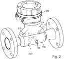
- Fig. 2 shows a structure of an ultrasonic flow meter 101, as it is already from the DE 10 2012 013 916 A1 and the DE 10 2013 105 922 A1 is known, to which reference is made in full within the scope of the present invention.
- How to get out Fig. 2 reflectors 103 are recognized in a measuring tube 102 of this ultrasonic flow meter 101. This is done by screwing the reflectors 103 into connections provided for this purpose. These screwed reflectors 103 are in Fig. 3 shown again in detail
- FIG. 1 Design variant shown in simplified form shows a Fig. 2 and 3 Modified embodiment variant according to the invention. To simplify matters, however, only a simplified section of a measuring tube 1 is shown here.
- This measuring tube 1 has a measuring tube wall 2.
- Fig. 1 shows the measuring tube wall 2 an integrally formed surface which deviates from the basic shape of the measuring tube wall, here in the form of a cylinder. This area is referred to below as functional area 4.
- a curved functional surface 4 is created instead of a flat one.
- This curved functional surface 4 is part of the measuring tube wall 2 serves to receive and guide a reflector element 3.
- a sectional view of the functional surface 4 describes a segment of a circle.
- the functional surface 4 is pressed into the measuring tube wall 2 from the inside and protrudes from the cylindrical basic shape of the measuring tube 1 on the outer circumference of the measuring tube 1.
- the shaping of the measuring tube can particularly preferably be carried out using an internal high-pressure forming process, also known as hydroforming.
- the contour of the measuring tube is deformed in some areas by an internal pressure. Since the inner tube space of the measuring tube does not have any sharp edges that obstruct the flow, this technique is particularly preferred.
- the production time of a measuring tube is particularly short with this forming technology.
- the curved functional surface primarily serves to guide and align the reflectors 3 in the measuring tube.
- a corresponding reflector 3 has a body with a partial cylinder surface, an ellipsoidal surface or, according to the invention, a partial spherical surface. This can, for example, as in Fig. 1 , shown to be connected directly to a reflection surface 5 or a separate body can be provided which is connected to the partial cylinder surface.
- the partial cylinder surface, ellipsoidal surface or spherical partial surface according to the invention assigned to the reflector preferably lies positively on the partial cylindrical surface, ellipsoidal surface or partial spherical surface according to the invention of the functional surface of the measuring tube wall.
- either the reflector or the functional surface may have webs and / or projections, the distal ends of which all end in at least one sectional view on the same circular segment.
- the reflector can then be aligned in the interior of the measuring tube in order to achieve the optimal sound path and then fixed on the measuring tube wall.
- Different technologies e.g. Gluing or soldering are used.
- welding the reflector to the measuring tube is particularly ideal, particularly in the area of the circle segment.
- the intermediate layer can particularly preferably also be a metal foil which, as a redox reaction, enables a material bond between the reflector and the measuring tube wall.
- a possible redox reaction is the thermite reaction.
- the reflectors can preferably be positioned and aligned using tools and tools and the angle can be preset.
- Fixation can then take place, for example, by means of a current surge.
- the particular advantage of this type of attachment is that the measuring tube does not require an opening for fixing at the location of the reflectors, and the measuring tube is therefore retained as a closed unit.
Landscapes
- Physics & Mathematics (AREA)
- Electromagnetism (AREA)
- Fluid Mechanics (AREA)
- General Physics & Mathematics (AREA)
- Measuring Volume Flow (AREA)
Description
Die vorliegende Erfindung betrifft ein Messrohr ausgeführt zum Einsatz in einem Ultraschall-Durchflussmessgerät nach dem Oberbegriff des Anspruchs 1, ein Ultraschall-Durchflussmessgerät mit einem Messrohr nach Anspruch 6 sowie ein Verfahren zur Herstellung eines Messrohres nach Anspruch 9.The present invention relates to a measuring tube designed for use in an ultrasonic flow measuring device according to the preamble of
Ultraschall-Durchflussmessgeräte werden vielfach in der Prozess- und Automatisierungstechnik eingesetzt. Sie erlauben in einfacher Weise, den Volumendurchfluss und/oder Massendurchfluss in einer Rohrleitung zu bestimmen.Ultrasonic flowmeters are widely used in process and automation technology. They allow the volume flow and / or mass flow in a pipeline to be determined in a simple manner.
Die bekannten Ultraschall-Durchflussmessgeräte arbeiten häufig nach dem Laufzeitdifferenz-Prinzip. Beim Laufzeitdifferenz-Prinzip werden die unterschiedlichen Laufzeiten von Ultraschallwellen, insbesondere Ultraschallimpulsen, so genannten Bursts, relativ zur Strömungsrichtung der Flüssigkeit ausgewertet. Hierzu werden Ultraschallimpulse in einem bestimmten Winkel zur Rohrachse sowohl mit als auch entgegen der Strömung gesendet. Aus der Laufzeitdifferenz lässt sich die Fließgeschwindigkeit und damit bei bekanntem Durchmesser des Rohrleitungsabschnitts der Volumendurchfluss bestimmen.The known ultrasonic flowmeters often work according to the time difference principle. In the transit time difference principle, the different transit times of ultrasonic waves, in particular ultrasonic pulses, so-called bursts, are evaluated relative to the direction of flow of the liquid. For this purpose, ultrasonic pulses are sent at a certain angle to the pipe axis both with and against the flow. From the transit time difference, the flow velocity and thus the volume flow rate can be determined if the diameter of the pipe section is known.
Die Ultraschallwellen werden mit Hilfe so genannter Ultraschallwandler erzeugt bzw. empfangen. Hierfür sind Ultraschallwandler in der Rohrwandung des betreffenden Rohrleitungsabschnitts fest angebracht. Es sind auch Clamp-on-Ultraschall-Durchflussmesssysteme erhältlich. Bei diesen Systemen werden die Ultraschallwandler von außerhalb des Messrohrs an dessen Rohrwand gepresst. Ein großer Vorteil von Clamp-On-Ultraschall-Durchflussmesssystemen ist, dass sie das Messmedium nicht berühren und auf eine bereits bestehende Rohrleitung angebracht werden. Die Ultraschallwandler bestehen normalerweise aus einem elektromechanischen Wandlerelement, z.B. ein piezoelektrisches Element, und einer Koppelschicht. Im elektromechanischen Wandlerelement werden die Ultraschallwellen als akustische Signale erzeugt und über die Koppelschicht zur Rohrwandung geführt und von dort in die Flüssigkeit geleitet, bei Clamp-On-Systemen, oder sie werden bei Inline-Systemen über die Koppelschicht in das Messmedium eingekoppelt. Dann wird die Koppelschicht auch seltener Membran genannt. Zwischen dem piezoelektrischen Element und der Koppelschicht kann eine weitere Koppelschicht angeordnet sein, eine so genannte Anpassungsschicht. Die Anpassungsschicht übernimmt dabei die Funktion der Transmission des Ultraschallsignals und gleichzeitig die Reduktion einer durch unterschiedliche akustische Impedanzen verursachte Reflexion an Grenzschichten zwischen zwei Materialen.The ultrasonic waves are generated or received using so-called ultrasonic transducers. For this purpose, ultrasonic transducers are firmly attached in the pipe wall of the relevant pipe section. Clamp-on ultrasonic flowmeters are also available. In these systems, the ultrasonic transducers are pressed from outside the measuring tube onto the tube wall. A great advantage of clamp-on ultrasonic flow measurement systems is that they do not touch the measuring medium and are attached to an existing pipe. The ultrasonic transducers usually consist of an electromechanical transducer element, e.g. a piezoelectric element, and a coupling layer. In the electromechanical transducer element, the ultrasonic waves are generated as acoustic signals and guided to the pipe wall via the coupling layer and from there into the liquid, in the case of clamp-on systems, or they are coupled into the measurement medium via the coupling layer in inline systems. Then the coupling layer is also called the membrane less often. A further coupling layer, a so-called adaptation layer, can be arranged between the piezoelectric element and the coupling layer. The adaptation layer takes on the function of the transmission of the ultrasound signal and at the same time the reduction of a reflection at boundary layers between two materials caused by different acoustic impedances.
Sowohl bei Clamp-On-Systemen, als auch bei Inline-Systemen sind die Ultraschallwandler in einer gemeinsamen Ebene am Messrohr angeordnet, entweder auf gegenüberliegenden Seiten des Messrohrs, dann verläuft das akustische Signal, projiziert auf einen Rohrquerschnitt, einmal entlang einer Sekante durch das Messrohr, oder auf derselben Seite des Messrohrs, dann wird das akustische Signal an der gegenüberliegenden Seite des Messrohrs reflektiert, wodurch das akustische Signal zweimal das Messrohr entlang der auf den Querschnitt durch das Messrohr projizierten Sekante durchquert. Die
Zur Gewichtung der Signalpfade gibt es verschiedene Arbeiten. Der Aufsatz "
Die
Die
Die
Die
Die
Eine Alternative bereits bekannte Variante ist das Gießen des Rohres und das Anschweißen von Stutzen am Messrohr und das anschließende Verschrauben oder Anschweißen einer Reflexionsfläche.An alternative variant that is already known is the casting of the tube and the welding of the sockets to the measuring tube and the subsequent screwing or welding of a reflection surface.
Aus der
Aus der
Aus der
Die
Die Aufgabe der Erfindung besteht darin, ein Ultraschall-Durchflussmessgerät mit mehreren Reflexionsflächen im Messrohr bereitzustellen, wobei das Messrohr mit verringerter Herstellzeit gefertigt werden kann, jedoch die Möglichkeit zur Festlegung hochgenau ausgerichteter Reflexionsflächen zur Vorgabe eines optimalen Signalpfades umfasst.The object of the invention is to provide an ultrasonic flow measuring device with a plurality of reflection surfaces in the measuring tube, the measuring tube being able to be manufactured with a reduced manufacturing time, but including the possibility of defining highly precisely aligned reflection surfaces for specifying an optimal signal path.
Die Aufgabe wird durch ein Messrohr mit den Merkmalen des Anspruchs 1 und durch ein Ultraschall-Durchflussmessgerät mit den Merkmalen des Anspruchs 6 gelöst.The object is achieved by a measuring tube with the features of
Ein erfindungsgemäßes Messrohr, ausgeführt zum Einsatz in einem Ultraschall-Durchflussmessgerät, umfasst eine Messrohrwandung und zumindest bereichsweise eine Grundform mit rotationssymmetrischem oder polygonalem Querschnitt. Es weist eine gerade Messrohrachse (M) auf.A measuring tube according to the invention, designed for use in an ultrasonic flow measuring device, comprises a measuring tube wall and at least in some areas a basic shape with a rotationally symmetrical or polygonal cross section. It has a straight measuring tube axis (M).
Das Messrohr weist zumindest eine Funktionsfläche zur Positionierung eines Reflektors auf, an welchem ein akustisches Signal auf einem Signalpfad reflektiert wird. Selbstverständlich kann im Fall eines sogenannten Zweitraversensystems bereits eine Funktionsfläche zur Positionierung eines einzigen Reflektors genügen. Dieser ermöglicht die Feineinstellung und die Feinausrichtung des Reflektors und der dazugehörigen Reflexionsfläche. Bei einem Messrohr, welches analog zur
Zumindest eine Funktionsfläche ist integral aus der Messrohrwandung ausgeformt. Sie ist nicht gegossen. Die Messrohrwandung ist vorzugsweise aus einem Metall gefertigt. Bekannterweise ist Metall duktil und lässt sich verformen. Ebenfalls bekannterweise erkennt der Fachmann einen Verformungsprozesse gegenüber einem Guss anhand der Ausrichtung des Metallgefüges im Schliffbild. Irgendwelche nachträglich angeschweißte oder angeklebte Funktionsflächen beruhen auch auf keinem Verformungsprozess, wie der Fachmann ebenfalls sofort an einem Schliffbild erkennen kann.At least one functional surface is integrally formed from the measuring tube wall. It is not cast. The measuring tube wall is preferably made of a metal. As is known, metal is ductile and can be deformed. As is also known, the person skilled in the art recognizes a deformation process compared to a casting on the basis of the orientation of the metal structure in the micrograph. Any functional surfaces that are subsequently welded or glued on are not based on any deformation process, as the person skilled in the art can also immediately recognize from a micrograph.
Die vorgenannte Funktionsfläche ist eine Kugelteilfläche und dient der Auflage eines Reflektors. Zumindest eine Funktionsfläche ist derart ausgerichtet, dass ein Messrohrabschnitt mit zumindest einer Funktionsfläche aus der Grundform des Messrohres nach außen hervorsteht.The aforementioned functional surface is a partial spherical surface and is used to support a reflector. At least one functional surface is oriented such that a measuring tube section with at least one functional surface protrudes outwards from the basic shape of the measuring tube.
Vorteilhafte Ausgestaltungen des erfindungsgemäßen Messrohres sind Gegenstand der entsprechenden Unteransprüche.Advantageous embodiments of the measuring tube according to the invention are the subject of the corresponding subclaims.
Es ist von Vorteil, wenn das Messrohr im Bereich zumindest einer Funktionsfläche eine geschlossene Messrohrwandung aufweist. Bei der Durchflussmessung ist eine Vermeidung von Bohrungen ein wichtiger Aspekt, Jede einzelne Bohrung muss auf Dichtigkeit bei den Mediumsdrücken geprüft werden. Zudem können verschiedene Medien das Dichtungsmaterial angreifen. Daher sollte das Messrohr lediglich ein Minimum an Bohrungen aufweisen.It is advantageous if the measuring tube has a closed measuring tube wall in the area of at least one functional surface. Avoiding holes is an important aspect of flow measurement. Each individual hole must be checked for leaks at the medium pressures. Various media can also attack the sealing material. Therefore, the measuring tube should only have a minimum of holes.
Es ist weiterhin von Vorteil, wenn das Messrohr mehrere Funktionsflächen zur Positionierung jeweils eines Reflektors aufweist, wobei das Ultraschallsignal auf dem Signalpfad mehrfach reflektiert wird. Dies betrifft insbesondere eine Mehrfachreflexion mit einem Signalverlauf, analog zur
Es ist von Vorteil, wenn das Messrohr im Übergangsbereich zwischen der Grundform der Messrohrwandung und zumindest einer Funktionsfläche eine Metallgefügestruktur aufweist, welche Metallgefügestruktur eine Orientierung in Verlaufsrichtung der Kontur des Messrohres aufweist. Das ist ein eindeutiger Nachweis auf das Herstellungsverfahren eines Umformverfahrens, mit welchem auch Messrohre geringer Blechstärke fertigbar sind. Dies betrifft insbesondere Messrohre mit einer Messrohrwandung aus Metallblech, vorzugsweise mit einer Blechdicke von 1-5 mm.It is advantageous if the measuring tube has a metal microstructure in the transition area between the basic shape of the measuring tube wall and at least one functional surface, which metal microstructure has an orientation in the direction of the contour of the measuring tube. This is clear evidence of the manufacturing process of a forming process with which measuring tubes of thin sheet thickness can also be manufactured. This applies in particular to measuring tubes with a measuring tube wall made of sheet metal, preferably with a sheet thickness of 1-5 mm.
Besonders von Vorteil ist es wenn die zumindest eine Funktionsfläche durch ein Innenhochdruck-Umformverfahren aus dem Messrohr ausgeformt ist.It is particularly advantageous if the at least one functional surface is formed from the measuring tube by an internal high-pressure forming process.
Ein erfindungsgemäßes Ultraschall-Durchflussmessgerät umfasst ein erfindungsgemäßes Messrohr ausgeführt zum Einsatz in einem Ultraschall-Durchflussmessgerät, einen Sender zum Senden eines akustischen Signals auf einem Signalpfad und einen Empfänger zum Empfangen des akustischen Signals auf dem Signalpfad.An ultrasonic flow measuring device according to the invention comprises a measuring tube according to the invention designed for use in an ultrasonic flow measuring device, a transmitter for transmitting an acoustic signal on a signal path and a receiver for receiving the acoustic signal on the signal path.
Das erfindungsgemäße Messrohr weist zumindest einen Reflektor mit jeweils zumindest einer Reflexionsfläche auf.The measuring tube according to the invention has at least one reflector, each with at least one reflection surface.
In einer ersten Ausführungsvariante der Erfindung weist der Reflektor eine Anbindungsfläche auf, welche in zumindest einer Schnittansicht ein Kreissegment definiert.In a first embodiment of the invention, the reflector has a connection surface which defines a segment of a circle in at least one sectional view.
Das Kreissegment ist komplementär zur Kreisteilfläche der Funktionsfläche des Messrohres ausgebildet ist. Das heißt es weist annähern das gleiche Bogenmaß auf. Der Reflektor ist auf der Funktionsfläche des Messrohres angeordnet.The circular segment is complementary to the circular partial surface of the functional surface of the measuring tube. That means it has approximately the same radian measure. The reflector is arranged on the functional surface of the measuring tube.
Durch das Zusammenspiel der Reflektoren mit den Funktionsflächen wird eine Feineinstellung der Reflexionsflächen zur Ausrichtung auf einen idealen Signalpfad gewährleistet.The interaction of the reflectors with the functional surfaces ensures a fine adjustment of the reflective surfaces to align them with an ideal signal path.
Vorteilhafte Ausgestaltungsvarianten eines Ultraschall-Durchflussmessgerätes sind Gegenstand der entsprechenden Unteransprüche Es ist von Vorteil das Messrohr mehrere Reflektoren aufweist, wobei das akustische Signal auf einem Signalpfad mehrfach reflektiert wird, insbesondere indem das akustische Signal jeweils an einer Reflexionsfläche eines jeden Reflektors zumindest einmal reflektiert wird.Advantageous design variants of an ultrasonic flow measuring device are the subject of the corresponding subclaims. It is advantageous that the measuring tube has a plurality of reflectors, the acoustic signal being reflected several times on a signal path, in particular by the acoustic signal being reflected at least once on a reflection surface of each reflector.
Zur Erfassung eines möglichst umfassenden Strömungsprofils ist es von Vorteil, wenn sich der Signalpfad aus geraden Teilabschnitten zusammensetzt, wobei
- a) jeweils die minimalen Abstände von mindestens drei Teilabschnitten
einen Abstand von 0,4-0,6 r zur Messrohrachse aufweisen, wobei r der Innenradius des Messrohres ist; - b) wobei ein erster Teilabschnitt, welcher eine erste achsparallele Ebene definiert, einen unmittelbar korrespondierenden zweiten Teilabschnitt aufweist, welcher eine zweite achsparallele Ebene definiert, beide Ebenen durch eine Reflexionsfläche eines ersten Reflektors verlaufen und die Normalvektoren einen Winkel von weniger als 10° einschließen,
- c) wobei ein dritter Teilabschnitt, welcher eine dritte achsparallele Ebene definiert, einen unmittelbar korrespondierenden vierten Teilabschnitt aufweist, welcher eine vierte achsparallele Ebene definiert,
- a) the minimum distances of at least three sections each have a distance of 0.4-0.6 r from the measuring tube axis, where r is the inner radius of the measuring tube;
- b) wherein a first section, which defines a first axis-parallel plane, has a directly corresponding second section, which defines a second axis-parallel plane, both planes run through a reflection surface of a first reflector and the normal vectors enclose an angle of less than 10 °,
- c) a third subsection, which defines a third axially parallel plane, has a directly corresponding fourth subsection, which defines a fourth axially parallel plane,
Es ist zudem von Vorteil, wenn das Ultraschall-Durchflussmessgerät einen Rotationsausgleich von rotierenden Strömungen berücksichtigt.It is also advantageous if the ultrasonic flow meter takes into account a rotation compensation of rotating flows.
Ein erfindungsgemäßes Verfahren zur Herstellung eines Messrohres ausgeführt zum Einsatz in einem Ultraschall-Durchflussmessgerät, umfasst die folgenden Schritte:
- a. Umformen eines Messrohr durch ein Umformverfahren, insbesondere durch ein Hochdruckumformverfahren, unter Einbringung von mehreren Funktionsflächen, eine Kreisteilfläche beschreibt;
- b. Positionieren von Reflektoren auf den Funktionsflächen, wobei der Reflektor eine zur Funktionsfläche komplementäre Fläche aufweist, wobei das Positionieren vorzugsweise derart erfolgt, dass ein Formenschluss mit zwischen Messrohrwand und Reflektor erreicht wird,
- c. Ausrichten der Reflektoren um einen vordefinierten Ultraschallsignalpfad einzustellen, und
- d. Festlegen der Reflektoren an der Messrohrwand.
- a. Forming a measuring tube by a forming process, in particular by a high-pressure forming process, with the introduction of several functional surfaces, describes a circular partial surface;
- b. Positioning of reflectors on the functional surfaces, the reflector having a surface complementary to the functional surface, the positioning preferably taking place in such a way that a positive fit is achieved with between the measuring tube wall and the reflector,
- c. Aligning the reflectors to set a predefined ultrasonic signal path, and
- d. Define the reflectors on the measuring tube wall.
Ein solches Verfahren ist produktionstechnisch einfach und sicher zu handhaben und kann bei exakter Einstellung des Signalpfades die Herstellungszeit und die Qualität des Messgerätes verbessern.Such a method is simple and safe to handle in terms of production technology and, if the signal path is precisely set, can improve the manufacturing time and the quality of the measuring device.
Besonders vorteilhaft kann das Festlegen der Reflektoren durch Einbringen einer folienartigen Zwischenschicht zwischen einer der Funktionsflächen eines Messrohres und einer Anbindungsfläche eines Reflektors erfolgt und durch Reactive Bonding erfolgen.It is particularly advantageous for the reflectors to be fixed by introducing a film-like intermediate layer between one of the functional surfaces of a measuring tube and a connection surface of a reflector and by reactive bonding.
Nachfolgend sind weitere vorteilhafte Ausgestaltungen eines erfindungsgemäßen Ultraschall-Durchflussmessgerätes beschrieben.Further advantageous configurations of an ultrasonic flow measuring device according to the invention are described below.
Das erfindungsgemäße Messrohr kann in einzelne Messrohrabschnitte bzw. Teilbereiche unterteilt sein, welche miteinander verschweißt oder miteinander integral nahtstellenfrei, also ohne Schweißnähte, verbunden sind. Letzteres ist bevorzugt, da die nahtlosen Übergänge der Messrohrabschnitte bzw. Teilbereiche besonders kostengünstig und zeitsparend herstellbar sind. Darüber hinaus kann ein zusätzlicher Fertigungsschritt und ein zusätzliches Bauteil eingespart werden. Die Grundform kann lediglich abschnittsweise, insbesondere über lediglich einen Messrohrabschnitt bzw. einen ersten Teilbereich des Messrohres, ausgebildet sein oder sich über den gesamten Messrohrverlauf erstrecken. Bekannte Grundformen mit rotationssymmetrischem oder polygonalem Querschnitt im Bereich des Rohrbaus sind beispielsweise Zylinderformen oder oftmals in Gasleitung eingesetzt Rohrleitungen mit quaderförmiger Mantelfläche. Selbstverständlich sind auch andere eher unübliche Rohrgeometrien, wie z.B. Rohre mit prismaförmigen Mantelflächen vom Gegenstand der Erfindung erfasst.The measuring tube according to the invention can be subdivided into individual measuring tube sections or partial areas, which are welded to one another or connected to one another integrally without any seams, that is to say without welding seams. The latter is preferred because the seamless transitions of the measuring tube sections or partial areas can be produced particularly inexpensively and in a time-saving manner. In addition, an additional manufacturing step and an additional component can be saved. The basic shape can only be formed in sections, in particular over only one measuring tube section or a first partial region of the measuring tube, or can extend over the entire course of the measuring tube. Known basic shapes with a rotationally symmetrical or polygonal cross section in the area of pipe construction are, for example, cylindrical shapes or often used in gas pipes, pipes with a cuboidal lateral surface. Of course, other rather unusual pipe geometries, such as Pipes with prism-shaped outer surfaces covered by the subject of the invention.
Das Ultraschall-Durchflussmessgerät weist darüber hinaus einen Sender zum Senden eines akustischen Signals auf einen Signalpfad und einen Empfänger zum Empfangen des akustischen Signals auf dem Signalpfad auf. Die Begriffe Sender und Empfänger sind im Rahmen der vorliegenden Erfindung derart zu verstehen, dass der Sender und der Empfänger durch ein- und denselben Ultraschallwandler gestellt werden können. Der entsprechende Ultraschallwandler weist in diesem Fall einen Betriebsmodus für den Sendebetrieb auf und fungiert in diesem Betriebsmodus als Sender. Er weist zudem einen Betriebsmodus für den Empfangsmodus auf und fungiert in diesem Betriebsmodus als Empfänger. Nach dem Aussenden eines Ultraschallsignals kann der Ultraschallwandler vom Sende- in den Empfangsmodus umschalten, während das Ultraschallsignal einen Signalpfad im Messrohr durchläuft. Das Ultraschallsignal kann beim Durchlauf auf senkrecht auf eine Reflexionsfläche geführt werden und auf dem bereits durchlaufenen Signalpfad bis zum Ultraschallwandler rückgeführt werden. Wenn das Ultraschallsignal auf den Ultraschallwandler rückgeführt wird, befindet sich dieser im Empfangsmodus und stellt einen Empfänger dar. Insofern wird der Sender und der Empfänger durch zwei Schaltungsanordnungen (eine Schaltung für den Sendemodus und eine Schaltung für den Empfangsmodus) in ein und demselben Ultraschallwandler realisiert. Wesentlich häufiger und vorrangig durch den Gegenstand der Erfindung erfasst ist jedoch eine Anordnung aus zumindest zwei Ultraschallwandlern als Sender und Empfänger, welche jeweils zwischen dem Sende- und Empfangsbetriebsmodus umschaltbar sind. Die Messung zur Ermittlung der Durchflussgeschwindigkeit oder des Volumenstromes wird mittels der an sich bekannten Laufzeitdifferenzmethode durchgeführt.The ultrasonic flow meter also has a transmitter for transmitting an acoustic signal on a signal path and a receiver for receiving the acoustic signal on the signal path. The terms transmitter and receiver are to be understood in the context of the present invention in such a way that the transmitter and the receiver can be set by one and the same ultrasound transducer. In this case, the corresponding ultrasound transducer has an operating mode for the transmission mode and functions as a transmitter in this operating mode. It also has an operating mode for the receive mode and acts as a receiver in this operating mode. After an ultrasound signal has been emitted, the ultrasound transducer can switch from the transmit mode to the receive mode while the ultrasound signal passes through a signal path in the measuring tube. During the passage, the ultrasonic signal can be guided vertically onto a reflection surface and can be returned to the ultrasonic transducer on the signal path that has already been passed. If the ultrasound signal is fed back to the ultrasound transducer, the latter is in the receive mode and represents a receiver. In this respect, the transmitter and the receiver are implemented in one and the same ultrasound transducer by two circuit arrangements (a circuit for the transmit mode and a circuit for the receive mode). However, an arrangement of at least two ultrasound transducers as transmitters and receivers, each of which can be switched between the transmit and receive operating modes, is significantly more frequently and primarily covered by the subject matter of the invention. The measurement to determine the flow rate or the volume flow is carried out using the known transit time difference method.
Die Messung beruht vorzugsweise auf einer Mehrfachreflexion des Ultraschallsignals im Messrohr. Vorzugsweise propagiert dabei das Ultraschallsignal in axialer Richtung durch das Messrohr ohne jedoch einen parallelen Verlauf zur Messrohrachse aufzuweisen. Die Mehrfachreflexion hat dabei insbesondere das Ziel Messstörungen, welche durch die Rotation der Strömung hervorgerufen werden, zu kompensieren.The measurement is preferably based on multiple reflection of the ultrasound signal in the measuring tube. The ultrasound signal preferably propagates in the axial direction through the measuring tube without, however, being parallel to the measuring tube axis. The multiple reflection has in particular the aim to compensate for measurement disturbances which are caused by the rotation of the flow.
Zur Realisierung der Mehrfachreflexion weist das Messrohr mehrere Reflektoren auf, an welchen das akustische Signal auf dem Signalpfad mehrfach reflektiert wird, vorzugsweise zumindest einmal an jeder Reflexionsfläche. Es eine Vielzahl von Messgeräten bekannt, welche eine Einfachreflexion an der Messrohrwandung - eine sogenannte Zweitraversenanordnung realisiert. Auch auf diese Zweitraversenanordnung kann die vorliegende Erfindung angewandt werden. Im vorliegenden Fall zielt die Anmeldung allerdings besonders bevorzugt auf eine Mehrfachreflexion ab, bei der das Ultraschallsignal mehrfach hintereinander im Messrohr auf Teilsignalpfaden reflektiert wird.To implement multiple reflection, the measuring tube has a plurality of reflectors, on which the acoustic signal on the signal path is reflected multiple times, preferably at least once on each reflection surface. A large number of measuring devices are known which implement a single reflection on the measuring tube wall - a so-called two-beam arrangement. The present invention can also be applied to this two-beam arrangement. In the present case, however, the application is particularly preferably aimed at multiple reflection, in which the ultrasonic signal is reflected several times in succession in the measuring tube on partial signal paths.
Die Funktionsflächen zur Aufnahme der Reflektoren sind dabei integral aus der Messrohrwandung ausgeformt. Integral ausgeformt bedeutet in diesem Zusammenhang, dass die Funktionsflächen nicht als gesondertes Bauteil an oder im Messrohr angeschweißt sind sondern durch die Messrohrwandung bereitgestellt werden. Die Messrohrwandung ist dabei im Bereich der Funktionsflächen verformt und weicht in diesem Bereich von seiner Grundform ab. Integral ausgeformte Reflexionsflächen sind aus der
Durch diese wesentlich variablere Ausrichtung der Reflektoren sind auch kompliziertere Signalpfadverläufe realisierbar und der Signalpfad kann hochpräzise eingestellt werden.This significantly more variable alignment of the reflectors also makes it possible to implement more complicated signal path profiles and the signal path can be set with high precision.
Die Funktionsflächen können vorausgerichtet sein und derart ausgerichtet vorliegen, dass mehrere der Funktionsflächen zumindest aus der Grundform des Messrohres nach außen hervorstehen. Durch diese Anordnung lassen sich optimierte Signalpfadverläufe sehr einfach realisieren.The functional surfaces can be pre-aligned and aligned such that several of the functional surfaces protrude outwards at least from the basic shape of the measuring tube. With this arrangement, optimized signal path profiles can be implemented very easily.
Die Funktionsflächen sind in die Messrohrwandung derart eingeformt, dass eine Mehrfachreflexion im Messrohr erfolgt, wobei der Signalpfad an zumindest drei in axialer Richtung hintereinander angeordneten Reflexionsflächen von Reflektoren reflektiert wird. Durch die hintereinander angeordneten Reflektoren kann eine Änderung des Strömungsprofils, welche sich über den vom Signalpfad definierten Messbereich entwickelt zumindest teilweise erfasst und kompensiert werden.The functional surfaces are molded into the measuring tube wall in such a way that multiple reflection takes place in the measuring tube, the signal path being reflected by at least three reflecting surfaces arranged one behind the other in the axial direction by reflectors. The reflectors arranged one behind the other can at least partially detect and compensate for a change in the flow profile which develops over the measurement range defined by the signal path.
Bei schnellen Strömungen kann das Ultraschallsignal vom idealen Auftreffpunkt auf der jeweiligen Reflexionsfläche abweichen. Diese Abweichung setzt sich an der darauffolgenden Reflexionsfläche fort und kann im schlimmsten Fall bei Mehrfachreflexionen zu einem Signalverlust führen. Dieser Fehler ist im Rahmen der vorliegenden Erfindung als Verwehung definiert. Um diese Verwehungen zu vermeiden ist es von Vorteil, wenn die Reflexionsfläche oder die Reflexionsflächen der Reflektoren vorzugsweise konvex mit einer Reflexionsflächenkrümmung ausgebildet sind. Zwar ist die Rohrwandung eines zylindrischen Rohres selbst auch konvex ausgebildet, allerdings unterscheidet sich die Kontur der Reflexionsflächenkrümmung bei der vorliegenden Reflexionsfläche von einer Krümmung der Messrohrwandung. Dieser Unterschied kann sich insbesondere in der unterschiedlich Kreisbogenlänge bei gleichbleibenden Kreiswinkel ergeben oder durch einen Mittelpunktswinkel ergeben, welcher einen Scheitelpunkt aufweist, welcher nicht auf der Messrohrachse liegt.In the case of fast currents, the ultrasound signal can deviate from the ideal point of impact on the respective reflection surface. This deviation continues on the subsequent reflection surface and, in the worst case, can lead to signal loss in the case of multiple reflections. This error is defined as drift in the context of the present invention. In order to avoid these drifts, it is advantageous if the reflection surface or the reflection surfaces of the reflectors are preferably convex with a reflection surface curvature. Although the tube wall of a cylindrical tube itself is also convex, the contour of the differs Reflection surface curvature in the present reflection surface from a curvature of the measuring tube wall. This difference can arise, in particular, in the different circular arc length with the circular angle remaining the same, or can result from a central angle which has a vertex which is not on the measuring tube axis.
Die zumindest eine Funktionsfläche ist vorteilhaft durch ein Innenhochdruck-Umformverfahren aus dem Messrohr ausgeformt. Das Innenhochdruck-Umformverfahren ist auch als Hydroforming bekannt. Dabei wird durch einen Innendruck eine Außenkontur verformt. Weiche abgerundete Übergänge zwischen den Messrohrelementen ist ein wesentliches Merkmal dieser Technik. Da der Innenrohrraum des Messrohres dadurch keine strömungsbehindernden scharfen Kanten aufweist, ist diese Technik besonders bevorzugt. Zudem ist die Produktionszeit eines Messrohres bei dieser Umformtechnik besonders gering.The at least one functional surface is advantageously formed from the measuring tube by an internal high-pressure forming process. The hydroforming process is also known as hydroforming. An outer contour is deformed by an internal pressure. Smooth rounded transitions between the measuring tube elements is an essential feature of this technique. Since the inner tube space of the measuring tube does not have any sharp edges that obstruct the flow, this technique is particularly preferred. In addition, the production time of a measuring tube is particularly short with this forming technology.
Der Anschlussstutzen kann aus der ebenen Funktionsfläche mittels eines Fließbohr-Prozesses ausgeformt werden. Dadurch wird der Anschlussstutzen durch Materialverdrängung integral aus der Messrohrwandung ausgeformt. Ein gesondertes Bauteil für den Anschlussstutzen muss daher nicht hergestellt und in einem gesonderten Fertigungsschritt verschweißt werden, was eine Arbeitszeit und Kostenreduzierung bedeutet. Besonders bevorzugt kann ein Gewinde in diesen Anschlussstutzen eingeformt werden.The connecting piece can be formed from the flat functional surface using a flow drilling process. As a result, the connecting piece is integrally formed from the measuring tube wall by material displacement. A separate component for the connection piece therefore does not have to be manufactured and welded in a separate production step, which means working time and cost reduction. A thread can particularly preferably be formed in this connecting piece.
Es ist von Vorteil, wenn das Messrohr einen oder mehrere weitere Messrohrabschnitte bzw. Teilbereiche des Messrohres aufweist, welche einen größeren Messrohrquerschnitt aufweisen als der erste Teilbereich des Messrohres, wobei die Vergrößerung dieser Messrohrabschnitte durch ein Innenhochdruck-Umformverfahren des Messrohres erfolgt. Durch ersten Teilbereich mit geringerem Messrohrquerschnitt wird eine Erhöhung des Messeffektes erzielt. Dies erfolgt durch eine Erhöhung der Durchflussgeschwindigkeit und dadurch ein größeres Δt bei der Messung nach der Laufzeitdifferenzmethode.It is advantageous if the measuring tube has one or more further measuring tube sections or partial areas of the measuring tube which have a larger measuring tube cross-section than the first partial area of the measuring tube, the enlargement of these measuring tube sections being effected by an internal high-pressure forming process of the measuring tube. The first partial area with a smaller measuring tube cross section increases the measuring effect. This is done by increasing the flow rate and thereby increasing the Δt when measuring using the transit time difference method.
Die Funktionsflächen sind insbesondere derart in das Messrohr eingeformt und die Reflektoren sind derart ausgerichtet, dass eine Ablenkung des Signalpfades derart erfolgt, dass zumindest drei aufeinanderfolgende Teilpfade des Signalpfades jeweils keinen Schnittpunkt mit der Messrohrachse aufweisen. Durch diese Anordnung wird das Strömungsprofil auf verschiedenen Ebenen erfasst. Symmetrische und asymmetrische Verwirbelungen im Strömungsprofil können besser ausgemittelt werden.The functional surfaces are in particular molded into the measuring tube and the reflectors are aligned such that the signal path is deflected in such a way that at least three successive partial paths of the signal path each have no intersection with the measuring tube axis. With this arrangement, the flow profile is recorded at different levels. Symmetrical and asymmetrical eddies in the flow profile can be better averaged out.
Der Verlauf des Signalpfades kann in axialer Draufsicht ein Vieleck beschreiben, dessen Seitenschnittpunkte innerhalb, auf oder außerhalb des Messrohres liegen. Durch diesen Signalpfadverlauf wird es dem Messgerät insbesondere ermöglicht einen Rotationsausgleich von rotierenden Strömungen bei der Messung zu berücksichtigen und zu kompensieren.
-
Fig. 1 axiale Draufsicht auf ein erfindungsgemäßes Ultraschall-Durchflussmessgerät; -
Fig. 2 teiltransparente Perspektivansicht eines Ultraschall-Durchflussmessgerätes aus dem Stand der Technik; und -
Fig. 3 Ansicht der Positionierung eines Reflektors in der Wandung des Messrohres des Ultraschall-Durchflussmessgerätes derFig. 2 .
-
Fig. 1 axial plan view of an ultrasonic flow meter according to the invention; -
Fig. 2 partially transparent perspective view of an ultrasonic flow meter from the prior art; and -
Fig. 3 View of the positioning of a reflector in the wall of the measuring tube of the ultrasonic flow meterFig. 2 ,
Ultraschall-Durchflussmessgeräte, wie das erfindungsgemäße Ultraschall-Durchflussmessgerät, werden vielfach in der Prozess- und Automatisierungstechnik eingesetzt. Sie erlauben in einfacher Weise, den Volumendurchfluss und/oder Massendurchfluss in einer Rohrleitung zu bestimmen. Die bekannten Ultraschall-Durchflussmessgeräte arbeiten häufig nach dem Laufzeitdifferenz Prinzip. Beim Laufzeitdifferenz-Prinzip werden die unterschiedlichen Laufzeiten von Ultraschallwellen, insbesondere Ultraschallimpulsen, so genannten Bursts, relativ zur Strömungsrichtung der Flüssigkeit ausgewertet. Hierzu werden Ultraschallimpulse in einem bestimmten Winkel zur Rohrachse sowohl mit als auch entgegen der Strömung gesendet. Aus der Laufzeitdifferenz lässt sich die Fliessgeschwindigkeit und damit bei bekanntem Durchmesser des Rohrleitungsabschnitts der Volumendurchfluss bestimmen.Ultrasonic flowmeters, such as the ultrasonic flowmeter according to the invention, are widely used in process and automation technology. They allow the volume flow and / or mass flow in a pipeline to be determined in a simple manner. The known ultrasonic flowmeters often work according to the transit time difference principle. In the transit time difference principle, the different transit times of ultrasonic waves, in particular ultrasonic pulses, so-called bursts, are evaluated relative to the direction of flow of the liquid. For this purpose, ultrasonic pulses are sent at a certain angle to the pipe axis both with and against the flow. From the transit time difference, the flow velocity and thus the volume flow rate can be determined if the diameter of the pipe section is known.
Die Ultraschallwellen werden mit Hilfe so genannter Ultraschallwandler erzeugt bzw. empfangen. Hierfür sind Ultraschallwandler in der Rohrwandung des betreffenden Rohrleitungsabschnitts fest angebracht. Es sind auch Clamp-on-Ultraschall-Durchflussmesssysteme erhältlich. Bei diesen Systemen werden die Ultraschallwandler von ausserhalb des Messrohrs an dessen Rohrwand gepresst. Im vorliegenden Fall handelt es sich jedoch vorzugsweise um ein sogenanntes Inline-Durchflussmessgerät, bei welchem die Ultraschallwandler fest im Messrohr integriert sind und das Ultraschallsignal direkt durch ein sogenanntes Ultraschallfenster vom Ultraschallwandler in das Medium eintritt.The ultrasonic waves are generated or received using so-called ultrasonic transducers. For this purpose, ultrasonic transducers are firmly attached in the pipe wall of the relevant pipe section. Clamp-on ultrasonic flowmeters are also available. In these systems, the ultrasonic transducers are pressed from outside the measuring tube onto the tube wall. In the present case, however, it is preferably a so-called inline flow meter, in which the ultrasound transducers are firmly integrated in the measuring tube and the ultrasound signal enters the medium directly through a so-called ultrasound window from the ultrasound transducer.
Die im erfindungsgemäßen Durchflussmessgerät werden üblicherweise Ultraschallwandler eingesetzt. Diese Ultraschallwandler bestehen normalerweise aus einem elektromechanischen Wandlerelement, z.B. ein piezoelektrisches Element und einer Koppelschicht. Zwischen dem piezoelektrischen Element und der Koppelschicht kann eine weitere Schicht angeordnet sein, eine so genannte Anpassungsschicht. Die Anpassungsschicht übernimmt dabei die Funktion der Transmission des Ultraschallsignals und gleichzeitig die Reduktion einer durch unterschiedliche akustische Impedanzen verursachte Reflexion an Grenzschichten zwischen zwei Materialen. Weitere sogenannte Koppel- und/oder Anpassungsschichten, sowie metallische Scheiben und/oder Schichten für die bessere Temperaturleitung können vorgesehen sein.The ultrasonic transducers are usually used in the flow measuring device according to the invention. These ultrasonic transducers usually consist of an electromechanical transducer element, e.g. a piezoelectric element and a coupling layer. A further layer, a so-called adaptation layer, can be arranged between the piezoelectric element and the coupling layer. The adaptation layer takes on the function of the transmission of the ultrasound signal and at the same time the reduction of a reflection at boundary layers between two materials caused by different acoustic impedances. Further so-called coupling and / or matching layers, as well as metallic disks and / or layers for better temperature conduction can be provided.
Sowohl bei den meisten aus dem Stand der Technik bekannten Clamp-On-Systemen, als auch bei den meisten aus dem Stand der Technik bekannten Inline-Systemen sind die Ultraschallwandler in einer gemeinsamen Ebene am Messrohr angeordnet, entweder auf gegenüberliegenden Seiten des Messrohrs, dann verläuft das akustische Signal, projiziert auf einen Rohrquerschnitt, einmal entlang einer Sekante durch das Messrohr, oder auf derselben Seite des Messrohrs, dann wird das akustische Signal an der gegenüberliegenden Seite des Messrohrs reflektiert, wodurch das akustische Signal zweimal das Messrohr entlang der auf den Querschnitt durch das Messrohr projizierten Sekante durchquert.Both in most of the clamp-on systems known from the prior art and in most of the inline systems known from the prior art, the ultrasonic transducers are arranged in a common plane on the measuring tube, either on opposite side of the measuring tube, then the acoustic signal is projected onto a tube cross-section, once along a secant through the measuring tube, or on the same side of the measuring tube, then the acoustic signal is reflected on the opposite side of the measuring tube, whereby the acoustic signal twice that Crosses measuring tube along the secant projected on the cross section through the measuring tube.
Im vorliegenden Ultraschall-Durchflussmessgerät erfolgt eine Mehrfachreflexion des Ultraschallsignals an Reflexionsflächen innerhalb des Messrohres. Durch die Aufsplittung in mehrere Signalpfade kann das Strömungsprofil des Ultraschall-Durchflussmessgerätes besser erfasst werden. Zudem können Strömungsrotationen und Strömungsverwirbelungen durch eine besonders günstige Führung des Signalpfades auf mehreren Teilsignalpfaden innerhalb des Messrohres ausgeglichen werden.In the present ultrasound flow meter, the ultrasound signal is reflected multiple times on reflection surfaces within the measuring tube. By splitting into several signal paths, the flow profile of the ultrasonic flow meter can be better captured. In addition, flow rotations and flow swirls can be compensated for by a particularly favorable routing of the signal path on several partial signal paths within the measuring tube.
In der Transparentdarstellung der
Diese Anordnung aus Sender, Empfänger, Transmitter 113 und Anschlussstück 114 und der Signalpfadverlauf sind baugleich auf die nachfolgenden
Die in
Anders als in
Die gebogene Funktionsfläche dient in erster Linie zur Führung und Ausrichtung der Reflektoren 3 im Messrohr. Dabei weist ein entsprechender Reflektor 3 einen Körper mit einer Zylinderteilfläche, Ellipsoidfläche oder erfindungsgemäß einer Kugelteilfläche auf. Dieser kann z.B. wie in
Es ist jedoch auch in einer weniger bevorzugten Ausführungsvariante möglich, dass entweder der Reflektor oder die Funktionsfläche Stege und/oder Vorsprünge aufweist, deren distale Enden in zumindest einer Schnittansicht alle auf demselben Kreissegment enden.However, in a less preferred embodiment variant it is also possible for either the reflector or the functional surface to have webs and / or projections, the distal ends of which all end in at least one sectional view on the same circular segment.
Der Reflektor kann sodann zum Erreichen des optimalen Schallpfades im Inneren des Messrohres ausgerichtet werden und dann an der Messrohrwand festgelegt werden. Zum Festlegen können unterschiedliche Technologien, so z.B. Kleben oder Löten zum Einsatz kommen. Besonders ideal ist jedoch ein Verschweißen des Reflektors mit dem Messrohr, insbesondere im Bereich des Kreissegments.The reflector can then be aligned in the interior of the measuring tube in order to achieve the optimal sound path and then fixed on the measuring tube wall. Different technologies, e.g. Gluing or soldering are used. However, welding the reflector to the measuring tube is particularly ideal, particularly in the area of the circle segment.
Es kann auch eine Befestigung unter Zuhilfenahme einer folienartigen Zwischenschicht erfolgen. Diese Befestigungstechnologie ist als "reactive bonding" bekannt und wird u.a.
Zusammenfassend umfasst eine besonders bevorzugte Ausführungsvariante zur Herstellung des Messrohres der vorbeschriebenen Art folgende Schritte:
- 1. Umformen eines Messrohr durch ein Umformverfahren, insbesondere durch ein Hochdruckumformverfahren, unter Einbringung von mehreren Funktionsflächen, von welchen jede Funktionsfläche in zumindest einer Schnittansicht ein Kreissegment beschreibt bzw. definiert als definierte Position für einen Reflektor;
- 2. Positionieren von Reflektoren auf den Funktionsflächen, wobei der Reflektor eine zur Funktionsfläche komplementäre Fläche aufweist, wobei das Positionieren vorzugsweise derart erfolgt, dass ein Formenschluss mit zwischen Messrohrwand und Reflektor erreicht wird,
- 3. Ausrichten der Reflektoren um einen vordefinierten Ultraschallsignalpfad einzustellen, und
- 4. Festlegen der Reflektoren, z.B. durch Scheißen.
- 1. Forming a measuring tube by a forming process, in particular by a high pressure forming process, with the introduction of several functional surfaces, from which each functional surface describes or defines as a defined position for a reflector in at least one sectional view;
- 2. Positioning of reflectors on the functional surfaces, the reflector having a surface complementary to the functional surface, the positioning preferably being carried out in such a way that a positive fit is achieved with between the measuring tube wall and the reflector,
- 3. Align the reflectors to set a predefined ultrasonic signal path, and
- 4. Set the reflectors, for example by shitting.
Das Positionieren und Ausrichten der Reflektoren kann vorzugsweise über Hilfsmittel und Werkzeuge erfolgen und der Winkel kann voreingestellt werden.The reflectors can preferably be positioned and aligned using tools and tools and the angle can be preset.
Durch Stromstoß kann dann beispielsweise eine Fixierung erfolgen.Fixation can then take place, for example, by means of a current surge.
Der besondere Vorteil dieser Art der Anbringung ist neben der Feinausrichtung der Reflektoren, dass das Messrohr an der Stelle der Reflektoren keine Öffnung zur Fixierung benötigt und somit das Messrohr als geschlossene Einheit erhalten bleibt.In addition to the fine alignment of the reflectors, the particular advantage of this type of attachment is that the measuring tube does not require an opening for fixing at the location of the reflectors, and the measuring tube is therefore retained as a closed unit.
Claims (10)
- Measuring tube (1) designed for use in an ultrasonic flowmeter, wherein said measuring tube (1) has a measuring tube wall (2) and
wherein said measuring tube (1) at least partially features a base form with a rotationally symmetric or polygonal cross-section and a straight measuring tube axis,
wherein the measuring tube (1) has at least one function surface (4) for the reflection of an acoustic signal on a signal path, and
wherein the at least one function surface (4) is integrally formed from the measuring tube wall (2)
characterized in that
the at least one function surface (4) is a spherical partial surface, which is designed for the positioning of a reflector (3) and serves to support the reflector (3),
wherein the at least one function surface (4) is aligned in such a way that a measuring tube section with the at least one function surface (4) projects externally out of the base form of the measuring tube. - Measuring tube as claimed in Claim 1, characterized in that the measuring tube (2) has a closed measuring tube wall (2) in the area of the at least one function surface (4).
- Measuring tube as claimed in Claim 1 or 2, characterized in that the measuring tube (1) has several function surfaces (4) for the positioning of one reflector (3) per surface, wherein the ultrasonic signal is reflected several times on the signal path.
- Measuring tube as claimed in one of the previous claims, characterized in that in the transition zone between the base form of the measuring tube wall (2) and the at least one function surface (4) the measuring tube (1) has a metal structure, wherein said metal structure has an orientation in the direction of the contour of the measuring tube (1).
- Measuring tube as claimed in one of the previous claims, characterized in that the measuring tube wall (2) is made from a metal plate, preferably with a plate thickness of 1 to 5 mm.
- Ultrasonic flowmeter, with
a measuring tube (1) as claimed in one of the previous claims, comprising
a transmitter to transmit an acoustic signal on a signal path and
a receiver to receive the acoustic signal on the signal path,
wherein the measuring tube (1) has at least one reflector (3) each with at least one reflection surface (5) and
wherein the reflector (3) has a connection surface, which defines a circle segment in at least one sectional view, wherein said circle segment is complementary to the spherical partial surface of the at least one function surface (4) of the measuring tube (1) and
wherein the reflector (3) is arranged on the at least one function surface (4) of the measuring tube (1). - Ultrasonic flowmeter as claimed in Claim 6, characterized in that the measuring tube (1) has multiple reflectors (3), wherein the acoustic signal is reflected multiple times on the signal path, particularly in that the acoustic signal is reflected at least once at a reflection surface (5) of each reflector (3).
- Ultrasonic flowmeter as claimed in one of the previous Claims 6 or 7, characterized in that the signal path is comprised of straight segments, characterized in thata) the minimum distances of at least three segments have a value of 0.4 to 0.6 r in relation to the measuring tube axis, r being the inner radius of the measuring tube (1);b) wherein a first segment, which defines a first plane parallel to the axis, has a second segment which corresponds directly, said second segment defining a second plane parallel to the axis, wherein the two planes pass through a reflection surface of a first reflector and the normal vectors enclose an angle of less than 10°,c) wherein a third segment, which defines a third plane parallel to the axis, has a fourth segment which corresponds directly, said fourth segment defining a fourth plane parallel to the axis,wherein the two planes pass through a second reflector with a reflection surface and the normal vectors enclose an angle of less than 10°.
- Procedure for the fabrication of a measuring tube designed to be used in an ultrasonic flowmeter as claimed in one of the Claims 1 to 5, wherein the fabrication comprises at least the following steps:a. Shaping of a measuring tube (2) by means of an internal high pressure forming process, with the introduction of multiple function surfaces (4), wherein each of the function surfaces (4) describes a spherical partial surface;b. Positioning of reflectors (3) on the function surfaces (4), wherein each reflector (3) has a connection surface that is complementary to the function surface (4), wherein the positioning is preferably implemented in such a way to obtain a positive fit between the measuring tube wall (2) and the reflector (3),c. Alignment of the reflectors (3) in order to set a predefined ultrasonic signal path, andd. Fastening of the reflectors (3) on the measuring tube wall (2).
- Procedure as claimed in Claim 9, characterized in that the fixing of the reflectors (3) is implemented by introducing a foil-like intermediate layer between one of the function surfaces (4) of a measuring tube (1) and a connection surface of a reflector (3) and by reactive bonding.
Applications Claiming Priority (2)
| Application Number | Priority Date | Filing Date | Title |
|---|---|---|---|
| DE102014118187.5A DE102014118187A1 (en) | 2014-12-09 | 2014-12-09 | Ultrasonic flowmeter |
| PCT/EP2015/075527 WO2016091477A1 (en) | 2014-12-09 | 2015-11-03 | Ultrasonic flow meter |
Publications (2)
| Publication Number | Publication Date |
|---|---|
| EP3230696A1 EP3230696A1 (en) | 2017-10-18 |
| EP3230696B1 true EP3230696B1 (en) | 2020-02-05 |
Family
ID=54545092
Family Applications (1)
| Application Number | Title | Priority Date | Filing Date |
|---|---|---|---|
| EP15794854.8A Active EP3230696B1 (en) | 2014-12-09 | 2015-11-03 | Ultrasonic flow meter |
Country Status (5)
| Country | Link |
|---|---|
| US (1) | US10634531B2 (en) |
| EP (1) | EP3230696B1 (en) |
| CN (1) | CN107110680B (en) |
| DE (1) | DE102014118187A1 (en) |
| WO (1) | WO2016091477A1 (en) |
Families Citing this family (9)
| Publication number | Priority date | Publication date | Assignee | Title |
|---|---|---|---|---|
| US20150315666A1 (en) * | 2014-04-30 | 2015-11-05 | Ford Global Technologies, Llc | Induction annealing as a method for expanded hydroformed tube formability |
| DE102014118187A1 (en) | 2014-12-09 | 2016-06-09 | Endress + Hauser Flowtec Ag | Ultrasonic flowmeter |
| FI129728B (en) * | 2016-06-27 | 2022-08-15 | Flaekt Woods Ab | Apparatus and method for measuring an air flow |
| DE102017110308A1 (en) * | 2017-05-12 | 2018-11-15 | Krohne Ag | Ultrasonic flowmeter |
| DK3665443T3 (en) * | 2017-08-08 | 2023-07-31 | Gwf Messsysteme Ag | FLOW METER AND MEASURING CHANNEL |
| EP3717873B1 (en) | 2017-12-03 | 2024-05-22 | Eugene Fourie | A flowmeter |
| EP3537112A1 (en) * | 2018-03-08 | 2019-09-11 | Energoflow AG | Fluid flow meter |
| JP6894863B2 (en) * | 2018-03-14 | 2021-06-30 | 株式会社キーエンス | Clamp-on type ultrasonic flow sensor |
| CN113295222A (en) * | 2020-02-21 | 2021-08-24 | 北京昌民技术有限公司 | Ultrasonic flowmeter |
Citations (1)
| Publication number | Priority date | Publication date | Assignee | Title |
|---|---|---|---|---|
| US20140083202A1 (en) * | 2011-05-17 | 2014-03-27 | Endress + Hauser Flowtec Ag | Ultrasonic, Flow Measuring Device |
Family Cites Families (28)
| Publication number | Priority date | Publication date | Assignee | Title |
|---|---|---|---|---|
| US4024760A (en) | 1975-07-25 | 1977-05-24 | Westinghouse Electric Corporation | Fluid flow measurement apparatus |
| US4103551A (en) | 1977-01-31 | 1978-08-01 | Panametrics, Inc. | Ultrasonic measuring system for differing flow conditions |
| US4610167A (en) | 1984-07-23 | 1986-09-09 | Westinghouse Electric Corp. | Apparatus for measuring flow velocity of fluids |
| WO1989001609A1 (en) | 1987-08-10 | 1989-02-23 | Siemens Aktiengesellschaft | Ultrasonic flow measurement installation |
| DE8904673U1 (en) | 1989-04-13 | 1989-06-08 | Siemens AG, 1000 Berlin und 8000 München | Flow measuring device for liquid media based on the ultrasonic transit time principle |
| EP0392294A1 (en) * | 1989-04-13 | 1990-10-17 | Siemens Aktiengesellschaft | Fluid flowmeter for measuring ultrasound transit times |
| EP0715155B1 (en) | 1994-12-02 | 2001-04-11 | Siemens Aktiengesellschaft | Ultrasonic flowmeter |
| DK171569B1 (en) * | 1995-01-31 | 1997-01-13 | Danfoss As | Ultrasonic flow meter "W" |
| DE19808701C2 (en) * | 1998-03-02 | 2000-01-20 | Georg F Wagner | Flow measuring device |
| DE19861073A1 (en) | 1998-03-02 | 1999-11-04 | Georg F Wagner | Flow measuring device with measuring pipe and ultrasonic transducers |
| JP2004520573A (en) * | 2000-11-30 | 2004-07-08 | ランディス+ギュル・ゲゼルシャフト・ミット・ベシュレンクテル・ハフツング | Flowmeter |
| DE10249542A1 (en) | 2002-10-23 | 2004-05-06 | Endress + Hauser Flowtec Ag, Reinach | Device for determining and / or monitoring the volume and / or mass flow of a medium |
| US20040129088A1 (en) * | 2002-12-30 | 2004-07-08 | D.C. Tigwell & Associates | Single-body dual-chip orthogonal sensing transit-time flow device using a parabolic reflecting surface |
| JP2004219290A (en) * | 2003-01-16 | 2004-08-05 | Nissan Motor Co Ltd | Ultrasonic flowmeter |
| DE10344893A1 (en) * | 2003-09-26 | 2005-04-21 | Bosch Gmbh Robert | Ultrasonic sensor and method for measuring flow velocities |
| DE10361763A1 (en) * | 2003-12-29 | 2005-07-28 | Robert Bosch Gmbh | Ultrasonic flow sensor with entangled transmitting and receiving elements |
| DE102004053673A1 (en) | 2004-11-03 | 2006-05-04 | Endress + Hauser Flowtec Ag | Device for determining and / or monitoring the volume and / or mass flow rate of a medium |
| DE102004060063B4 (en) | 2004-12-14 | 2016-10-20 | Robert Bosch Gmbh | Device for flow measurement by means of ultrasound |
| DE102005022048A1 (en) | 2005-05-09 | 2006-11-16 | Endress + Hauser Flowtec Ag | Device for determining and / or monitoring the volume and / or mass flow rate of a measuring medium |
| GB0816823D0 (en) * | 2008-09-13 | 2008-10-22 | Cxr Ltd | X-ray tubes |
| DE102008055030A1 (en) | 2008-12-19 | 2010-07-01 | Endress + Hauser Flowtec Ag | Measuring tube of an ultrasonic flow measuring system |
| CN102288328A (en) * | 2011-05-12 | 2011-12-21 | 铜陵德瑞曼电子科技有限公司 | Ultrasonic heat meter base tube |
| DE102011079250A1 (en) * | 2011-07-15 | 2013-01-17 | Endress + Hauser Flowtec Ag | Ultrasonic flowmeter |
| DE102012101098A1 (en) * | 2012-02-10 | 2013-08-14 | Endress + Hauser Flowtec Ag | Ultrasonic flowmeter and method for determining the flow rate or volumetric flow of a fluid |
| DE102012013916A1 (en) | 2012-07-16 | 2014-01-16 | Endress + Hauser Flowtec Ag | Ultrasonic flowmeter |
| DE102013105407A1 (en) | 2013-05-27 | 2014-11-27 | Endress + Hauser Flowtec Ag | Device for determining and / or monitoring the volume and / or mass flow of a medium |
| DE102013105922A1 (en) | 2013-06-07 | 2014-12-11 | Endress + Hauser Flowtec Ag | Ultrasonic flowmeter |
| DE102014118187A1 (en) | 2014-12-09 | 2016-06-09 | Endress + Hauser Flowtec Ag | Ultrasonic flowmeter |
-
2014
- 2014-12-09 DE DE102014118187.5A patent/DE102014118187A1/en not_active Withdrawn
-
2015
- 2015-11-03 WO PCT/EP2015/075527 patent/WO2016091477A1/en active Application Filing
- 2015-11-03 EP EP15794854.8A patent/EP3230696B1/en active Active
- 2015-11-03 US US15/528,903 patent/US10634531B2/en active Active
- 2015-11-03 CN CN201580067482.5A patent/CN107110680B/en active Active
Patent Citations (1)
| Publication number | Priority date | Publication date | Assignee | Title |
|---|---|---|---|---|
| US20140083202A1 (en) * | 2011-05-17 | 2014-03-27 | Endress + Hauser Flowtec Ag | Ultrasonic, Flow Measuring Device |
Also Published As
| Publication number | Publication date |
|---|---|
| US20170314977A1 (en) | 2017-11-02 |
| CN107110680B (en) | 2020-10-23 |
| US10634531B2 (en) | 2020-04-28 |
| CN107110680A (en) | 2017-08-29 |
| WO2016091477A1 (en) | 2016-06-16 |
| EP3230696A1 (en) | 2017-10-18 |
| DE102014118187A1 (en) | 2016-06-09 |
Similar Documents
| Publication | Publication Date | Title |
|---|---|---|
| EP3230696B1 (en) | Ultrasonic flow meter | |
| EP3004812B1 (en) | Ultrasonic flowmeter | |
| EP2732248B1 (en) | Ultrasonic flow meter | |
| DE2458901C3 (en) | Flow meter | |
| EP2386835B1 (en) | Ultrasound measurement of the flow speed of a fluid in a tubular conduit | |
| EP2370795B1 (en) | Measuring system for determining and/or monitoring the flow rate of a measured medium through the measuring tube using ultrasound | |
| EP2103911B1 (en) | Flow measurement with ultrasound | |
| EP1975575A2 (en) | Flow meter | |
| DE102014107697A1 (en) | Ultrasonic Flow Meter | |
| EP2710336B1 (en) | Ultrasonic flowmeter | |
| EP2306160A1 (en) | Measuring insert and flow meter | |
| DE102012013916A1 (en) | Ultrasonic flowmeter | |
| DE102008029772A1 (en) | Method and measuring system for determining and / or monitoring the flow of a measuring medium through a measuring tube | |
| EP1993742A2 (en) | Device for determining and/or monitoring the volume or mass flow rate of a medium in a pipe conduit | |
| DE10254053B4 (en) | Method and device for determining and / or monitoring a volume and / or mass flow | |
| DE102006038620A1 (en) | Flowmeter | |
| WO2012156197A1 (en) | Ultrasonic flowmeter | |
| DE102008013224A1 (en) | Measuring system for determining and/or monitoring flow of measuring medium through measuring tube, has measuring tube, where signal path runs and partly lies in partial volume of tube on plane | |
| WO2013117457A1 (en) | Ultrasonic flowmeter and method for determining the flow speed and/or the volumetric flow of a fluid | |
| DE102013218827A1 (en) | Section control valve | |
| DE102010063789A1 (en) | Ultrasonic flowmeter | |
| EP2179253A1 (en) | Coupling element for an ultrasonic flow measuring device | |
| EP3273205A1 (en) | Method and assembly for ultrasound clamp on flow measurement and body for realizing the measurement | |
| EP3612802B1 (en) | Ultrasonic type flow measuring device | |
| EP3855134A1 (en) | Device for measuring the flow speed of a fluid |
Legal Events
| Date | Code | Title | Description |
|---|---|---|---|
| STAA | Information on the status of an ep patent application or granted ep patent |
Free format text: STATUS: THE INTERNATIONAL PUBLICATION HAS BEEN MADE |
|
| PUAI | Public reference made under article 153(3) epc to a published international application that has entered the european phase |
Free format text: ORIGINAL CODE: 0009012 |
|
| STAA | Information on the status of an ep patent application or granted ep patent |
Free format text: STATUS: REQUEST FOR EXAMINATION WAS MADE |
|
| 17P | Request for examination filed |
Effective date: 20170517 |
|
| AK | Designated contracting states |
Kind code of ref document: A1 Designated state(s): AL AT BE BG CH CY CZ DE DK EE ES FI FR GB GR HR HU IE IS IT LI LT LU LV MC MK MT NL NO PL PT RO RS SE SI SK SM TR |
|
| AX | Request for extension of the european patent |
Extension state: BA ME |
|
| DAV | Request for validation of the european patent (deleted) | ||
| DAX | Request for extension of the european patent (deleted) | ||
| STAA | Information on the status of an ep patent application or granted ep patent |
Free format text: STATUS: EXAMINATION IS IN PROGRESS |
|
| 17Q | First examination report despatched |
Effective date: 20180709 |
|
| GRAP | Despatch of communication of intention to grant a patent |
Free format text: ORIGINAL CODE: EPIDOSNIGR1 |
|
| STAA | Information on the status of an ep patent application or granted ep patent |
Free format text: STATUS: GRANT OF PATENT IS INTENDED |
|
| INTG | Intention to grant announced |
Effective date: 20190917 |
|
| GRAS | Grant fee paid |
Free format text: ORIGINAL CODE: EPIDOSNIGR3 |
|
| GRAA | (expected) grant |
Free format text: ORIGINAL CODE: 0009210 |
|
| STAA | Information on the status of an ep patent application or granted ep patent |
Free format text: STATUS: THE PATENT HAS BEEN GRANTED |
|
| AK | Designated contracting states |
Kind code of ref document: B1 Designated state(s): AL AT BE BG CH CY CZ DE DK EE ES FI FR GB GR HR HU IE IS IT LI LT LU LV MC MK MT NL NO PL PT RO RS SE SI SK SM TR |
|
| REG | Reference to a national code |
Ref country code: GB Ref legal event code: FG4D Free format text: NOT ENGLISH |
|
| REG | Reference to a national code |
Ref country code: AT Ref legal event code: REF Ref document number: 1230245 Country of ref document: AT Kind code of ref document: T Effective date: 20200215 |
|
| REG | Reference to a national code |
Ref country code: DE Ref legal event code: R096 Ref document number: 502015011646 Country of ref document: DE |
|
| REG | Reference to a national code |
Ref country code: IE Ref legal event code: FG4D Free format text: LANGUAGE OF EP DOCUMENT: GERMAN |
|
| REG | Reference to a national code |
Ref country code: CH Ref legal event code: EP |
|
| REG | Reference to a national code |
Ref country code: NL Ref legal event code: MP Effective date: 20200205 |
|
| PG25 | Lapsed in a contracting state [announced via postgrant information from national office to epo] |
Ref country code: NO Free format text: LAPSE BECAUSE OF FAILURE TO SUBMIT A TRANSLATION OF THE DESCRIPTION OR TO PAY THE FEE WITHIN THE PRESCRIBED TIME-LIMIT Effective date: 20200505 Ref country code: PT Free format text: LAPSE BECAUSE OF FAILURE TO SUBMIT A TRANSLATION OF THE DESCRIPTION OR TO PAY THE FEE WITHIN THE PRESCRIBED TIME-LIMIT Effective date: 20200628 Ref country code: RS Free format text: LAPSE BECAUSE OF FAILURE TO SUBMIT A TRANSLATION OF THE DESCRIPTION OR TO PAY THE FEE WITHIN THE PRESCRIBED TIME-LIMIT Effective date: 20200205 Ref country code: FI Free format text: LAPSE BECAUSE OF FAILURE TO SUBMIT A TRANSLATION OF THE DESCRIPTION OR TO PAY THE FEE WITHIN THE PRESCRIBED TIME-LIMIT Effective date: 20200205 |
|
| REG | Reference to a national code |
Ref country code: LT Ref legal event code: MG4D |
|
| PG25 | Lapsed in a contracting state [announced via postgrant information from national office to epo] |
Ref country code: GR Free format text: LAPSE BECAUSE OF FAILURE TO SUBMIT A TRANSLATION OF THE DESCRIPTION OR TO PAY THE FEE WITHIN THE PRESCRIBED TIME-LIMIT Effective date: 20200506 Ref country code: HR Free format text: LAPSE BECAUSE OF FAILURE TO SUBMIT A TRANSLATION OF THE DESCRIPTION OR TO PAY THE FEE WITHIN THE PRESCRIBED TIME-LIMIT Effective date: 20200205 Ref country code: BG Free format text: LAPSE BECAUSE OF FAILURE TO SUBMIT A TRANSLATION OF THE DESCRIPTION OR TO PAY THE FEE WITHIN THE PRESCRIBED TIME-LIMIT Effective date: 20200505 Ref country code: LV Free format text: LAPSE BECAUSE OF FAILURE TO SUBMIT A TRANSLATION OF THE DESCRIPTION OR TO PAY THE FEE WITHIN THE PRESCRIBED TIME-LIMIT Effective date: 20200205 Ref country code: IS Free format text: LAPSE BECAUSE OF FAILURE TO SUBMIT A TRANSLATION OF THE DESCRIPTION OR TO PAY THE FEE WITHIN THE PRESCRIBED TIME-LIMIT Effective date: 20200605 Ref country code: SE Free format text: LAPSE BECAUSE OF FAILURE TO SUBMIT A TRANSLATION OF THE DESCRIPTION OR TO PAY THE FEE WITHIN THE PRESCRIBED TIME-LIMIT Effective date: 20200205 |
|
| PG25 | Lapsed in a contracting state [announced via postgrant information from national office to epo] |
Ref country code: NL Free format text: LAPSE BECAUSE OF FAILURE TO SUBMIT A TRANSLATION OF THE DESCRIPTION OR TO PAY THE FEE WITHIN THE PRESCRIBED TIME-LIMIT Effective date: 20200205 |
|
| PG25 | Lapsed in a contracting state [announced via postgrant information from national office to epo] |
Ref country code: CZ Free format text: LAPSE BECAUSE OF FAILURE TO SUBMIT A TRANSLATION OF THE DESCRIPTION OR TO PAY THE FEE WITHIN THE PRESCRIBED TIME-LIMIT Effective date: 20200205 Ref country code: RO Free format text: LAPSE BECAUSE OF FAILURE TO SUBMIT A TRANSLATION OF THE DESCRIPTION OR TO PAY THE FEE WITHIN THE PRESCRIBED TIME-LIMIT Effective date: 20200205 Ref country code: ES Free format text: LAPSE BECAUSE OF FAILURE TO SUBMIT A TRANSLATION OF THE DESCRIPTION OR TO PAY THE FEE WITHIN THE PRESCRIBED TIME-LIMIT Effective date: 20200205 Ref country code: SK Free format text: LAPSE BECAUSE OF FAILURE TO SUBMIT A TRANSLATION OF THE DESCRIPTION OR TO PAY THE FEE WITHIN THE PRESCRIBED TIME-LIMIT Effective date: 20200205 Ref country code: DK Free format text: LAPSE BECAUSE OF FAILURE TO SUBMIT A TRANSLATION OF THE DESCRIPTION OR TO PAY THE FEE WITHIN THE PRESCRIBED TIME-LIMIT Effective date: 20200205 Ref country code: LT Free format text: LAPSE BECAUSE OF FAILURE TO SUBMIT A TRANSLATION OF THE DESCRIPTION OR TO PAY THE FEE WITHIN THE PRESCRIBED TIME-LIMIT Effective date: 20200205 Ref country code: SM Free format text: LAPSE BECAUSE OF FAILURE TO SUBMIT A TRANSLATION OF THE DESCRIPTION OR TO PAY THE FEE WITHIN THE PRESCRIBED TIME-LIMIT Effective date: 20200205 Ref country code: EE Free format text: LAPSE BECAUSE OF FAILURE TO SUBMIT A TRANSLATION OF THE DESCRIPTION OR TO PAY THE FEE WITHIN THE PRESCRIBED TIME-LIMIT Effective date: 20200205 |
|
| REG | Reference to a national code |
Ref country code: DE Ref legal event code: R097 Ref document number: 502015011646 Country of ref document: DE |
|
| PLBE | No opposition filed within time limit |
Free format text: ORIGINAL CODE: 0009261 |
|
| STAA | Information on the status of an ep patent application or granted ep patent |
Free format text: STATUS: NO OPPOSITION FILED WITHIN TIME LIMIT |
|
| 26N | No opposition filed |
Effective date: 20201106 |
|
| PG25 | Lapsed in a contracting state [announced via postgrant information from national office to epo] |
Ref country code: IT Free format text: LAPSE BECAUSE OF FAILURE TO SUBMIT A TRANSLATION OF THE DESCRIPTION OR TO PAY THE FEE WITHIN THE PRESCRIBED TIME-LIMIT Effective date: 20200205 |
|
| PG25 | Lapsed in a contracting state [announced via postgrant information from national office to epo] |
Ref country code: PL Free format text: LAPSE BECAUSE OF FAILURE TO SUBMIT A TRANSLATION OF THE DESCRIPTION OR TO PAY THE FEE WITHIN THE PRESCRIBED TIME-LIMIT Effective date: 20200205 Ref country code: SI Free format text: LAPSE BECAUSE OF FAILURE TO SUBMIT A TRANSLATION OF THE DESCRIPTION OR TO PAY THE FEE WITHIN THE PRESCRIBED TIME-LIMIT Effective date: 20200205 |
|
| PG25 | Lapsed in a contracting state [announced via postgrant information from national office to epo] |
Ref country code: MC Free format text: LAPSE BECAUSE OF FAILURE TO SUBMIT A TRANSLATION OF THE DESCRIPTION OR TO PAY THE FEE WITHIN THE PRESCRIBED TIME-LIMIT Effective date: 20200205 |
|
| REG | Reference to a national code |
Ref country code: CH Ref legal event code: PL |
|
| GBPC | Gb: european patent ceased through non-payment of renewal fee |
Effective date: 20201103 |
|
| PG25 | Lapsed in a contracting state [announced via postgrant information from national office to epo] |
Ref country code: LU Free format text: LAPSE BECAUSE OF NON-PAYMENT OF DUE FEES Effective date: 20201103 |
|
| REG | Reference to a national code |
Ref country code: BE Ref legal event code: MM Effective date: 20201130 |
|
| PG25 | Lapsed in a contracting state [announced via postgrant information from national office to epo] |
Ref country code: LI Free format text: LAPSE BECAUSE OF NON-PAYMENT OF DUE FEES Effective date: 20201130 Ref country code: CH Free format text: LAPSE BECAUSE OF NON-PAYMENT OF DUE FEES Effective date: 20201130 |
|
| PG25 | Lapsed in a contracting state [announced via postgrant information from national office to epo] |
Ref country code: FR Free format text: LAPSE BECAUSE OF NON-PAYMENT OF DUE FEES Effective date: 20201130 Ref country code: IE Free format text: LAPSE BECAUSE OF NON-PAYMENT OF DUE FEES Effective date: 20201103 |
|
| PG25 | Lapsed in a contracting state [announced via postgrant information from national office to epo] |
Ref country code: GB Free format text: LAPSE BECAUSE OF NON-PAYMENT OF DUE FEES Effective date: 20201103 |
|
| REG | Reference to a national code |
Ref country code: AT Ref legal event code: MM01 Ref document number: 1230245 Country of ref document: AT Kind code of ref document: T Effective date: 20201103 |
|
| PG25 | Lapsed in a contracting state [announced via postgrant information from national office to epo] |
Ref country code: AT Free format text: LAPSE BECAUSE OF NON-PAYMENT OF DUE FEES Effective date: 20201103 |
|
| PG25 | Lapsed in a contracting state [announced via postgrant information from national office to epo] |
Ref country code: TR Free format text: LAPSE BECAUSE OF FAILURE TO SUBMIT A TRANSLATION OF THE DESCRIPTION OR TO PAY THE FEE WITHIN THE PRESCRIBED TIME-LIMIT Effective date: 20200205 Ref country code: MT Free format text: LAPSE BECAUSE OF FAILURE TO SUBMIT A TRANSLATION OF THE DESCRIPTION OR TO PAY THE FEE WITHIN THE PRESCRIBED TIME-LIMIT Effective date: 20200205 Ref country code: CY Free format text: LAPSE BECAUSE OF FAILURE TO SUBMIT A TRANSLATION OF THE DESCRIPTION OR TO PAY THE FEE WITHIN THE PRESCRIBED TIME-LIMIT Effective date: 20200205 |
|
| PG25 | Lapsed in a contracting state [announced via postgrant information from national office to epo] |
Ref country code: MK Free format text: LAPSE BECAUSE OF FAILURE TO SUBMIT A TRANSLATION OF THE DESCRIPTION OR TO PAY THE FEE WITHIN THE PRESCRIBED TIME-LIMIT Effective date: 20200205 Ref country code: AL Free format text: LAPSE BECAUSE OF FAILURE TO SUBMIT A TRANSLATION OF THE DESCRIPTION OR TO PAY THE FEE WITHIN THE PRESCRIBED TIME-LIMIT Effective date: 20200205 |
|
| PG25 | Lapsed in a contracting state [announced via postgrant information from national office to epo] |
Ref country code: BE Free format text: LAPSE BECAUSE OF NON-PAYMENT OF DUE FEES Effective date: 20201130 |
|
| P01 | Opt-out of the competence of the unified patent court (upc) registered |
Effective date: 20230601 |
|
| PGFP | Annual fee paid to national office [announced via postgrant information from national office to epo] |
Ref country code: DE Payment date: 20231121 Year of fee payment: 9 |