EP2370795B1 - Measuring system for determining and/or monitoring the flow rate of a measured medium through the measuring tube using ultrasound - Google Patents
Measuring system for determining and/or monitoring the flow rate of a measured medium through the measuring tube using ultrasound Download PDFInfo
- Publication number
- EP2370795B1 EP2370795B1 EP09774894.1A EP09774894A EP2370795B1 EP 2370795 B1 EP2370795 B1 EP 2370795B1 EP 09774894 A EP09774894 A EP 09774894A EP 2370795 B1 EP2370795 B1 EP 2370795B1
- Authority
- EP
- European Patent Office
- Prior art keywords
- measuring tube
- ultrasonic transducer
- measuring
- ultrasonic
- transducer
- Prior art date
- Legal status (The legal status is an assumption and is not a legal conclusion. Google has not performed a legal analysis and makes no representation as to the accuracy of the status listed.)
- Not-in-force
Links
Images


Classifications
-
- G—PHYSICS
- G01—MEASURING; TESTING
- G01F—MEASURING VOLUME, VOLUME FLOW, MASS FLOW OR LIQUID LEVEL; METERING BY VOLUME
- G01F1/00—Measuring the volume flow or mass flow of fluid or fluent solid material wherein the fluid passes through a meter in a continuous flow
- G01F1/66—Measuring the volume flow or mass flow of fluid or fluent solid material wherein the fluid passes through a meter in a continuous flow by measuring frequency, phase shift or propagation time of electromagnetic or other waves, e.g. using ultrasonic flowmeters
- G01F1/662—Constructional details
Definitions
- the present invention relates to a measuring system for determining and / or monitoring the flow of a measuring medium through the measuring tube by means of ultrasound, with a first ultrasonic transducer and at least one further second ultrasonic transducer, wherein the measuring tube has a measuring tube inlet and a measuring tube outlet and a first ultrasonic transducer holder and at least one further second ultrasonic transducer receiving, wherein the first ultrasonic transducer is releasably coupled acoustically with the first ultrasonic transducer recording of the measuring tube and wherein the second ultrasonic transducer is releasably coupled to the second ultrasonic transducer recording of the measuring tube acoustically.
- Ultrasonic flowmeters are widely used in process and automation technology. They allow in a simple way to determine the volume flow and / or mass flow in a pipeline.
- the known ultrasonic flowmeters often work according to the Doppler or the transit time difference principle.
- ultrasonic pulses are sent at a certain angle to the pipe axis both with and against the flow.
- the runtime difference can be used to determine the flow velocity and, with a known diameter of the pipe section, the volume flow rate.
- ultrasonic waves of a certain frequency are coupled into the liquid and the ultrasonic waves reflected by the liquid are evaluated. From the frequency shift between the coupled and reflected waves can also determine the flow rate of the liquid.
- the ultrasonic waves are generated or received with the help of so-called ultrasonic transducers.
- ultrasonic transducers on the pipe wall of the respective pipe section firmly attached.
- clamp-on ultrasonic flow measurement systems have become available. In these systems, the ultrasonic transducers are pressed against the pipe wall only with a tension lock.
- Such systems are for. B. from the EP 686 255 B1 . US-A 44 84 478 or US-A 45 98 593 known.
- Another ultrasonic flowmeter which operates on the transit time difference principle, is from the US-A 50 52 230 known.
- the transit time is determined here by means of short ultrasound pulses.
- a big advantage of clamp-on ultrasonic flow measuring systems is that they do not touch the measuring medium and are mounted on an existing pipeline.
- the ultrasound transducers normally consist of a piezoelectric element, also called piezo for short, and a coupling layer, also known as a coupling wedge or, more rarely, a precursor body.
- the coupling layer is usually made of plastic
- the piezoelectric element is in industrial process measurement usually a piezoceramic.
- the ultrasonic waves are generated and passed over the coupling layer to the pipe wall and passed from there into the liquid. Since the speeds of sound in liquids and plastics are different, the ultrasonic waves are refracted during the transition from one medium to another.
- the angle of refraction is determined in first approximation according to Snell's law. The angle of refraction is thus dependent on the ratio of the propagation velocities in the media.
- a further coupling layer may be arranged, a so-called adaptation layer.
- the adaptation layer assumes the function of the transmission of the ultrasonic signal and at the same time the reduction of a reflection caused by different acoustic impedances at boundary layers between two materials.
- the coupling elements corresponding input and / or decoupling surfaces, each having a Have angles to the piezoelectric elements, which in turn are arranged plane-parallel to each other and perpendicular to the Meßrohrachse.
- the sound-emitting or sound-receiving surfaces of the piezoelectric elements are at least the size of the diameter of the measuring tube.
- a disadvantage of angles between the sound-emitting or sound-receiving surfaces of the piezoelectric elements and the input and output surfaces of the coupling elements is that the sound velocities in the coupling elements and the measuring tube and / or in the measuring medium must be coordinated with each other and with the angles to one for Receive tube axis parallel signal path of the ultrasonic signal.
- the EP 1 760 436 A2 shows an ultrasonic flow measuring system with a measuring tube, which is axially ultrasonically transposed, with piezoelectric elements having a diameter of the sound-emitting or sound-receiving surfaces, which is at least equal to the diameter of the measuring tube.
- the input and / or decoupling surfaces of the coupling elements of the ultrasonic transducers for coupling or decoupling the ultrasonic signals into the measuring medium are convex.
- the measuring tube Immediately before the input and / or decoupling surfaces, ie in the region of the coupling or decoupling of the ultrasonic signals into or out of the measuring medium, the measuring tube has an enlarged cross section.
- the diameters of the substantially disk-shaped ultrasonic transducers are larger than the diameter of a substantial measuring section of the measuring tube. Due to the change in cross section of the measuring tube before the input and / or decoupling arise just before the input and / or decoupling chambers, where the measuring medium can collect.
- the flow of the measuring medium is slowed down before the input and / or decoupling surfaces and accelerated in the measuring tube, in a substantial part of the measuring section.
- the WO 2008/101662 A2 has a similar design of the measuring cell.
- the diameters of the measuring tube or measuring tube outlets and of the measuring tube itself are essentially the same here, the measuring tube inlet or measuring tube outlets are at an angle of less than 90 ° on the measuring tube axis, but here too the flow of the measuring medium before the inlet and / or or decoupling surfaces, which are again formed here by the coupling elements of the ultrasonic transducers inserted into the measuring cell and are arranged at an angle of 90 ° to the measuring tube axis, slows down.
- chambers are formed in front of the input and output surfaces.
- the sound-emitting or sound-receiving surfaces of the piezoelectric elements are larger than the diameter of the measuring tube, but the sound input or sound output surface of the coupling element axially closes the measuring tube and is therefore of the same size.
- the ultrasonic transducer can be detachably mounted to the measuring tube by means of a bayonet, screw, clip or snap lock.
- a measuring tube which in the region of an ultrasonic transducer receiving pin part of a bayonet closure, and an ultrasonic transducer is designed as a matching counterpart or as a matching second part of the bayonet closure and the measuring tube thus by means of rotation is detachably attachable.
- the invention has for its object to provide a high-precision measuring system with inexpensive exchangeable measuring tubes / measuring cells.
- a measuring system for determining and / or monitoring the flow of a measuring medium through a measuring tube with a first ultrasonic transducer and at least one further second ultrasonic transducer, wherein the measuring system comprises the measuring tube and a first ultrasonic transducer and at least one further second ultrasonic transducer, wherein the Measuring tube has a measuring tube inlet and a measuring tube outlet and a first ultrasonic transducer recording and at least one further, second ultrasonic transducer recording, wherein the first ultrasonic transducer is releasably coupled to the first ultrasonic transducer recording of the measuring tube acoustically and wherein the second ultrasonic transducer is detachably acoustically coupled to the second ultrasonic transducer recording of the measuring tube, wherein at least one ultrasonic transducer has at least one bracket, which bracket can be folded over and is designed such that the bracket in at least one arranged on the measuring tube survey or Recess is lat
- At least one ultrasonic transducer has at least one stirrup, which stirrup can be folded over and is designed such that the stirrup can be latched in at least one elevation or depression arranged on the measuring tube in a folded-over, and thus closed, state while simultaneously assuming the mounting position of the ultrasound transducer on the measuring tube
- the ultrasonic transducer engages in a recess or survey, hooks or even embraces it
- the ultrasonic transducer is detachably mounted on the measuring tube with the latching of the bracket and is acoustically coupled to the ultrasonic transducer recording of the measuring tube.
- the determination and / or monitoring of the flow takes place, for example, according to the principle of the transit time difference.
- Bumps or depressions are in particular cones, shoulders, annular grooves, Wellenschultem etc. They are e.g. Part of a shaft / hub connection or a spring / groove connection.
- the ultrasonic transducer and the depressions or elevations on the measuring tube are part of a fastening mechanism, in particular a closure.
- a fastening mechanism in particular a closure.
- the ultrasonic transducer is brought into the mounting position and automatically brought by folding the bracket in the measuring position. It is in particular a linear movement, which is forced to the ultrasonic transducer.
- an annular groove e.g. provided as a notch at the top of the measuring tube. In this the clip lock engages. If this notch also extends only partially around the transducer receptacle, an annular groove results from the notch, which can be regarded as a journal.
- One embodiment provides a closure, as is customary especially in travel suitcases, a so-called suitcase closure.
- the measuring tube has at least two pins on opposite sides of the measuring tube in the region of at least one ultrasonic transducer receptacle on the measuring tube outside.
- a pin designates in particular a projecting piece for the transmission of forces, in particular a remote end of an axle that can accommodate a bearing. spigot serve to connect components together.
- the pins lie in one axis.
- this axis lies in the spatial plane, which is spanned by the measuring tube axis and the measuring tube outlet axis and / or the measuring tube inlet axis.
- the part of the fastening mechanism which is arranged on the ultrasonic transducer consists of a bracket, e.g. a clamping yoke, and a clamping bracket, e.g. a tensioning lever, both of which are connected to each other via a first closure axis, wherein at least the bracket is rotatably mounted on the first closure axis, and a second closure axis, which connects the clamping bracket with the ultrasonic transducer housing, wherein at least the clamping bracket is rotatably mounted on the second closure axis.
- the bracket By turning the clamping bracket around the second locking axis, the bracket is folded over. He experiences a translational motion perpendicular to the second closure axis.
- At least one ultrasonic transducer has at least one first guide element for guiding the ultrasonic transducer on a base plate and the base plate has at least one, corresponding to the first guide element of the ultrasonic transducer matching second guide element for guiding the ultrasonic transducer on the base plate, wherein the first guide element and the second guide element are each part of a linear guide.
- the guide means are thus suitable for substantially fixing the ultrasonic transducer on the base plate in two cardinal directions, i. store immovably and to store in one direction at least over a certain area displaceable.
- the ultrasonic transducers are in particular secured against rotation relative to the base plate on the base plate.
- the measuring tube on the base plate attachable and the sensors also, which are still arranged in the direction of the measuring tube and away from it displaceable on the base plate.
- the base plate is not necessary to align and / or fix the ultrasonic transducers on the measuring tube, it is optional, ie it serves only as a support or as a mounting base for the whole measuring system, then mounting holes are provided on its underside to themselves to attach in the process. If it makes sense in the application, it is possible to disassemble the base plate and thus make the whole system more flexible and flexible.
- the measuring tube has at least one plug or at least one coupling for producing a plug connection between measuring tube and base plate on the measuring tube outside and the base plate corresponding to at least one plug or at least one coupling for producing the plug connection between measuring tube and Base plate has.
- This is optional, but it is also possible that no direct or no force and / or positive and / or cohesive connection between the base plate and the measuring tube is provided.
- the elevations or depressions in the region of the ultrasonic transducer recordings are arranged on the measuring tube.
- One embodiment provides pins in the range of ultrasonic transducer recordings.
- the ultrasound transducers each have at least one electromechanical transducer element or at least one electromechanical transducer element and at least one coupling element, which coupling elements are arranged between the electromechanical transducer elements of the ultrasound transducer and the ultrasound transducer receptacles of the measuring tube in the mounted state of the ultrasound transducer, which electromechanical transducer elements or which coupling elements can be coupled by means of a definable force with the ultrasonic transducer recordings of the measuring tube.
- the part of the ultrasonic transducer which is acoustically coupled during assembly with the measuring tube, so the electromechanical transducer element itself or a coupling element, which then stands between the electromechanical transducer element and the measuring tube, is prepared with a predetermined bias to the measuring tube or on the measuring tube to it Pressed ultrasound transducer recordings.
- the force can be applied by means of a spring between an ultrasonic transducer housing and a sensor cup, wherein the electromechanical transducer element is arranged on the sensor cup.
- the sensor cup is a component which is mounted displaceably relative to the ultrasound transducer housing only in one direction, in particular in the ultrasound transducer housing itself.
- the electromechanical transducer element is then attached or attached to a first side of the sensor cup.
- On the other side of the sensor cup is the spring.
- the spring thus provides the contact pressure for acoustic coupling of the ultrasonic transducer on the measuring tube.
- the ultrasonic transducer is by means of springs in the ultrasonic transducer, the electromechanical transducer element or the sound emitting and / or receiving surface of the upstream coupling element of the ultrasonic transducer on or on the Transducer receiving surface of the respective ultrasonic transducer recording, in particular pressed with a predetermined or adjustable force.
- the force results from the bias of the spring and, according to one embodiment, is the same for each assembly.
- a further development of the measuring system according to the invention suggests that the ultrasonic transducer receptacles are arranged in the region of the measuring tube inlet and / or in the region of the measuring tube outlet.
- the ultrasonic transducers each have at least one electromechanical transducer element, wherein the measuring tube is configured with the ultrasound transducer recordings so that the electromechanical transducer elements in the assembled state of the ultrasound transducers on the measuring tube are substantially coplanar in pairs.
- the ultrasonic transducer recordings are pot-shaped, with the respective transducer receiving surface of the ultrasonic transducer recording as a pot bottom, and the parts of the ultrasonic transducer, which are inserted into the cup-shaped ultrasonic transducer recordings, or are introduced during assembly, have an insignificantly smaller size.
- the ultrasonic transducers, in particular the coupling elements and / or the electromechanical transducer elements fit into the ultrasound transducer recordings in such a way that a movement of the ultrasound transducers in four of six degrees of freedom is limited or no longer possible.
- a movement in the axial direction to the cup-shaped ultrasonic transducer recording and a rotation about this axis is determined by folding the bracket, without the position of the ultrasonic transducer itself is again significantly changed.
- the base plate is designed such that cables of the ultrasonic transducers are concealed on or in the base plate and / or can be protected against external influences.
- the electromechanical transducer elements of the ultrasonic transducer are substantially smaller than the inner diameter of the measuring tube.
- the ultrasonic transducers each have at least two electromechanical transducer elements.
- the first and second ultrasonic transducers each have two electromechanical transducer elements which face each other in pairs, resulting in two measurement paths.
- the ultrasonic transducers and so that both of your electromechanical transducer elements can be coupled to the measuring tube simultaneously with the fastening mechanism.
- FIG. 1 an inventive measuring tube 3 of a measuring system 1 according to the invention is shown schematically in section.
- the measuring tube 3 has in each case a first measuring tube inlet 4 and a first measuring tube outlet 5.
- the measuring tube inlet 4 has a cross section approximately constant over its length. This is in this embodiment approximately equal to the cross section of the measuring tube 3, both in shape and in size.
- the measuring tube outlet 5, however, is slightly conical, so that the cross section of the measuring tube outlet 5, which adjoins the measuring tube, is slightly larger than the cross section of the measuring tube outlet 5, which can be used as a process connection.
- Both the measuring tube axis 8, and the measuring tube inlet axis 9 and the measuring tube outlet axis 10 lie in a spatial plane, here the drawing plane, wherein the measuring tube inlet 4 and the measuring tube outlet 5 are arranged on opposite sides of the measuring tube 3.
- Disc-shaped electromechanical transducer elements 6 and 7, for converting electrical signals into ultrasonic signals and / or vice versa, are acoustically coupled to ultrasonic transducer receptacles 23 and 24.
- the ultrasonic transducer receptacles 23 and 24 have a substantially cylindrical shape. They assume the function of coupling the ultrasonic signals into the measuring medium 2.
- the ultrasonic signals from the electromechanical Transducer elements 6, 7 generates and coupled to the transducer receiving surfaces in the Ultraschallwandleraidn 23 and 24, which in turn direct the ultrasonic signals to the measuring medium 2 and via their sound input and sound output surfaces 16 and 17 couple the ultrasonic signals in the measuring medium 2.
- the ultrasound signals are guided by the measuring medium 2 back to the electromechanical transducer elements, they are coupled out of the measuring medium 2 at the sound in or sound outcoupling surfaces 16 and 17 and guided by the ultrasound transducer receptacles 23 and 24 up to the electromechanical transducer elements 6, 7.
- the sound input or sound output surfaces 16 and 17 are smaller here than the surfaces of the electromechanical transducer elements 6, 7.
- the ultrasound transducer recordings 23 and 24 have the shape of an exponential horn, at least in the area of the sound in or sound outcoupling surfaces 16 and 17.
- the ultrasonic signals propagate along a so-called signal or measurement path. A straight-line measuring path is modeled here.
- the wavefronts of the ultrasonic signal are substantially perpendicular to the measurement path.
- Both the sound in or sound outcoupling surfaces 16 and 17, and the electromechanical transducer elements 6, 7 and the transducer receiving surfaces of the ultrasonic transducer receptacles 23 and 24 have a substantially circular cross-section.
- the midpoints 27, 28 of the sound in or Schallauskoppel inhabit 16 and 17 and the centers of the electromechanical transducer elements 6, 7 and the transducer receiving surfaces of the Ultraschallwandler techniquen 23 and 24 are on a single straight.
- the measurement path is considered to coincide with the connecting line 11 between the centers 12 and 13 of the electromechanical transducer elements 6, 7 and thus the angle ⁇ between the connecting line 11 between the centers 12 and 13 of the first and second electromechanical transducer element 6, 7 and between the measuring tube axis 8 and the angle ⁇ between the connecting line between the centers of the sound in and / or Schallauskoppel inhabit 16, 17 and the measuring tube axis 8 and the angle ⁇ between the connecting line between the centers of the wall and the measuring tube axis 8 equal and equal to the angle ⁇ of the measuring path.
- the measuring path or signal path which here is equal to the connecting line 11 between the centers 12 and 13 of the electromechanical transducer elements 6, 7, is slightly inclined to the measuring tube axis 8.
- the angle ⁇ or ⁇ here is about 5 °.
- the measuring path 11 extends completely on the side of the measuring tube axis 8, on which the measuring tube outlet 5 is located.
- a first imaginary room level is, as already described, spanned by the measuring tube axis 8 and the measuring tube inlet and measuring tube outlet axes 9 and 10.
- a second imaginary plane is then perpendicular to the first imaginary plane and intersects the first imaginary plane in a first cut line. In this embodiment, this first cutting line is the measuring tube axis 8 itself.
- the connecting line between the centers of the sound inlet and / or sound output surfaces 16, 17 or here the measuring path does not intersect the second imaginary plane.
- the measuring path 11 is located on the side of the second imaginary plane, on which the measuring tube outlet 5 is also arranged on the measuring tube 3.
- the surfaces of the electromechanical transducer element 6, 7, the transducer mounting surfaces and in particular the sound input and / or sound output surfaces 16, 17 are smaller than the free cross section of the measuring tube 3, which here is derivable from the inner diameter of the measuring tube 3.
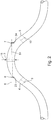
- Fig. 2 discloses a measuring system 1 according to the invention with a further measuring tube 3 according to the invention.
- the measuring tube 3 has an approximately circular cross-section and a short longitudinal extent relative to its diameter.
- the measuring tube inlet 4 and the measuring tube outlet 5 have approximately the same and circular cross-sections. Again, these are short relative to their cross sections.
- the measuring tube inlet 4 and the measuring tube outlet 5 do not directly adjoin the measuring tube 3. However, they are each connected to it via an intermediate tube 73, 74.
- the intermediate tubes 73, 74 are curved and / or bent. A definition of straight axes in the intermediate tubes 73, 74 is therefore not easily possible.
- Both the measuring tube 3, as well as the measuring tube inlet 4 and the measuring tube outlet 5, here have a certain length with a straight central axis 8, 9, 10, on which all centers of the respective tube 3, 4, 5 lie.
- the measuring tube outlet axis 10 and measuring tube axis 8 span a first imaginary plane, that is to say both the measuring tube outlet axis 10 and the measuring tube axis 8 lie in the first imaginary plane, here the drawing plane. Perpendicular to this first imaginary plane extends a second imaginary plane, wherein the measuring tube axis 8 lies in this second imaginary plane, the measuring tube axis 8 is thus part of the first line of intersection between the first and second imaginary plane.
- the connecting line between the center points of the first and second electromechanical transducer elements 6 and 7, which face one another in a plane-parallel manner, which here equals equal to the inscribed measuring path, now runs on the side of the measuring tube outlet and does not intersect the second level.
- the measuring path lies in an imaginary third plane which, in parallel with the second imaginary plane, bisects the inner diameter 15 of the measuring tube 3.
- the propagation of the ultrasonic waves generated by the electromechanical transducer elements 6 and 7, the measured transit time difference in and against the flow of the measuring medium in the measuring tube 3 is included in the calculation of the flow.
- the measuring path 54 is arranged in a region of the measuring tube 3, where a flow profile known by calibration is present due to the particular shape of the measuring tube 3, the measuring path 54 is e.g. In a flow which is accelerated in comparison with the flow prevailing in the region of the measuring tube axis, the quality of the measurement or determination of the flow, in particular for viscous measuring media or altogether very slow flows and / or flow rates, is increased.
- Fig. 3 shows a further inventive measuring tube 3 of a measuring system 1 according to the invention schematically shown in section. It has essentially the same cross sections of the measuring tube inlet 4 and outlet 5 and of the measuring tube 3. Both the measuring tube inlet 4, and the measuring tube outlet 5 have an angle of approximately 45 ° to the measuring tube axis, so ⁇ ⁇ ⁇ ⁇ 45 °. Furthermore, the measuring tube 3 has four ultrasonic transducer receptacles 23, 24, 45, 46. The Ultraschallwandleringn 23, 24, 45, 46 are each designed cup-shaped. Electromechanical transducer elements 6, 7, 19, 20 can be introduced into the cup-shaped ultrasonic transducer receptacles 23, 24, 45, 46.
- the ultrasonic transducer receptacles 23, 24, 45, 46 then serve as coupling elements between the electromechanical transducer elements 6, 7, 19, 20 and the measuring medium 2 in the measuring tube 3.
- the electromechanical transducer elements 6, 7, 19, 20 are connected to the transducer mounting surfaces 29, 30, 52, 53 of the ultrasonic transducer recording 23, 24, 45, 46 acoustically coupled.
- the transducer receiving surfaces 29, 30, 52, 53 equally represent the cup inner bottoms of the cup-shaped ultrasonic transducer receptacles 23, 24, 45, 46.
- this angle ⁇ is 0 ° or 180 °, ie the connecting line 26 and measuring tube axis 8 are parallel to one another.
- the four ultrasonic transducer holders 23, 24, 45, 46 lie opposite each other in pairs, the first and the third ultrasonic transducer holders 23, 45 lying in the region of the measuring tube inlet 4 and the second and fourth ultrasonic transducer holders 24, 46 being arranged in the region of the measuring tube outlet 5.
- Both measuring paths are parallel to the measuring tube axis 8, i.
- both the electromechanical transducer elements 6, 7, 19, 20 and the sound coupling and / or sound output surfaces 16, 17, 47, 48 are substantially smaller than the measuring tube diameter 15th
- the measuring tube 8 divides the cross section of the inner diameter 15 of the measuring tube 3 into two equal parts. As also easily recognizable, this divided inner diameter 15 is in turn divided by the first measuring path 54.
- the opposite Schalleinkoppel- and / or Schallauskoppel lake 16 and 17 are completely and clearly on the side of the measuring tube axis 8, on which the measuring tube outlet 5 is located. Therefore, the first measuring path 54 is also clearly beyond a line which third the inner diameter 15 of the measuring tube 3.
- the first measuring path 15 is even on the side of a so-called quarter plane, ie a plane parallel to a second imaginary space plane, which quarter plane the inner diameter 15 of the measuring tube 3 quarters, on which side of the imaginary quarter plane and the measuring tube outlet 5 is arranged, the second imaginary spatial plane is perpendicular to a first spatial plane, with the measuring tube axis 8 as a cutting line between the first and second spatial plane, which first spatial plane of the measuring tube axis 8 and the measuring tube outlet 5 is spanned.
- quarter plane ie a plane parallel to a second imaginary space plane, which quarter plane the inner diameter 15 of the measuring tube 3 quarters, on which side of the imaginary quarter plane and the measuring tube outlet 5 is arranged
- the second imaginary spatial plane is perpendicular to a first spatial plane, with the measuring tube axis 8 as a cutting line between the first and second spatial plane, which first spatial plane of the measuring tube axis 8 and the measuring tube outlet 5 is spanned.
- the measuring tube 3 has on its inside two rings 14, which reduce the free cross section of the measuring tube 3.
- the rings protrude 1/10 of the inside diameter of the measuring tube into the measuring tube. Every ring has a distance of the measuring tube inlet 4 and / or outlet 5 closest to it from 0 to 1/2 of the measuring tube length to one another. Through the rings, a linearization of the measurement characteristic is achieved, but at the same time requires a change in the algorithm for Reynoldswasbetician.
- Fig. 4 are different coupling elements drawn in cross section.
- the signal energy of the electromechanical transducer element 6 is bundled. This is advantageous for the emission of ultrasound signals.
- the enlargement of the cross-sectional area from the transducer receiving surface 29 to the sound input and / or sound output surface 16 acts as a funnel for incoming ultrasonic signals. Your signal energy is in turn bundled before hitting the electromechanical transducer element 6.
- the directivity and the sensitivity / radiation power is optimized by the various coupling elements to their respective application.
- the coupling elements take on different shapes. Shown is only a selection without claim to completeness. In addition to the gradation of the coupling element and coupling elements in the form of a truncated cone or an exponential horn are shown. It is also conceivable a system of acoustic lenses.
- Fig. 5 3 schematically outlines an inventive measuring system 1.
- the measuring system comprises a base plate 62, with a coupling, not shown, for fixing the measuring tube 3.
- the measuring tube 3 in turn has a suitable for coupling the base plate 62 plug 43.
- the measuring tube 3 is detachably connected to the base plate 62 and secured against rotation and displacement. Only by unplugging the measuring tube 3 can be moved relative to the base plate 62.
- the measuring tube 3 has a measuring tube inlet 4 and a measuring tube outlet 5, which lie here in a spatial plane.
- the measuring system 1 comprises a first ultrasonic transducer 58 and a second ultrasonic transducer 59.
- the second ultrasonic transducer 59 is in this embodiment, similar to the measuring tube 3, plugged onto the base plate 62 and detachably connected thereto.
- the second ultrasonic transducer 59 is only by unplugging relative to the base plate 62 to move.
- the first ultrasonic transducer 58 is mounted coaxially to the measuring tube axis displaceable on the base plate 62. He has a first, not embodied here, guide element, which together with a second guide member 68 of the Base plate 62 ensures the displacement of the first ultrasonic transducer 58.
- the second guide member 68 is a T-groove.
- An attached to the first ultrasonic transducer 58 and appropriately designed rail allows the positive connection of the first ultrasonic transducer 58 and base plate 62 with simultaneous degree of freedom of the first ultrasonic transducer 58 coaxial with the measuring tube axis.
- the first ultrasonic transducer 58 is pushed for mounting on the measuring tube 3 and coupled acoustically by moving the first bracket 56 to the measuring tube 3.
- Both the first ultrasonic transducer 58 has a first bracket 56
- the second ultrasonic transducer 59 has a second bracket 57.
- the brackets 56, 57 are designed so that they hook into the arranged on the measuring tube 3 and the ultrasonic transducer receptacles 23, 24 pins 39, 40, 41 in the folded state and thus the ultrasonic transducers 58 and 59 on the measuring tube 3 releasably secure.
- One possible embodiment of the mechanics of attachment is in the Fig. 8a and 8b presents.
- the brackets 56, 57 are folded over and the ultrasonic transducers 58 and 59 are mounted or released again from the measuring tube.
- Fig. 5 shows the ultrasonic transducer 58 and 59 in the assembled state and thus the bracket 56 and 57 in the folded or closed state.
- the clamping brackets 75 and 76 serve here simultaneously as securing bracket or locking lever.
- the Fig. 6a and 6b describe the measuring tube 3 with a measuring tube inlet 4 and a measuring tube outlet 5, as in Fig. 5 is still shown mounted on the base plate.
- feet 43 are provided for docking the measuring tube 3 on a base plate on the measuring tube 3 and the pins 39, 40, 41 for coupling ultrasonic transducers. On the feet 43, the measuring tube 3 is merely supported on the base plate. The base plate in this case would not have a coupling.
- the measuring tube 3 is not connectable to the base plate here and only held in position via the ultrasonic transducers. However, supporting the measuring tube on the baseplate can be very useful during installation.
- the first ultrasonic transducer holder 23 is designed cup-shaped. A first transducer receiving surface 29 forms the bottom of the pot of the ultrasonic transducer recording 23. At this first transducer receiving surface 29, the first electromechanical transducer element 6 is acoustically coupled directly or indirectly via a first coupling element of the first ultrasonic transducer.
- the first ultrasonic transducer holder 23 has guide rails 77. These serve here for alignment and guidance of the first ultrasonic transducer coaxial with the measuring tube axis.
- Fig. 7 shows a cross section through an inventive measuring system 1 with a measuring tube according to the invention a first ultrasonic transducer 58 and a base plate 62.
- the first ultrasonic transducer 58 has a first electromechanical transducer element 6, by means of which received ultrasonic signals are converted into electrical signals or which converts electrical signals into ultrasonic signals.
- the first electromechanical transducer element 6 is arranged at the tip of a so-called sensor cup 71.
- the sensor cup 71 is guided in the first ultrasonic transducer holder 23.
- the first electromechanical transducer element 6 is in approximately acoustically gapless contact with the first transducer receiving surface 29 of the first ultrasonic transducer holder 23.
- the centers of the first transducer receiving surface 29 of the first ultrasonic transducer holder 23 and the first electromechanical transducer element 6 lie on an axis which axis is equal to the connecting line between the centers the first sound input and / or sound output surface 16 of the first ultrasonic transducer recording 23 and the second sound input and / or sound output surface of the second ultrasonic transducer recording and thus is equal to the first measuring path.
- the first ultrasonic transducer holder 23 is shown cup-shaped with the first transducer receiving surface 29 as a pot bottom.
- the spring force of the coil spring 69 is in turn dependent, inter alia, on the position of the first ultrasonic transducer 58 relative to the first transducer receiving surface 29. This is in the assembled state, so if the bracket 56 are folded, by moving the first clamping bracket, here a clamping lever 75, and have intervened in the pin on the measuring tube, only affected by manufacturing tolerances of the individual components. Adjusting this spring force by means of an adjusting screw 78.
- the adjusting screw 78 is connected to the housing 70 of the first ultrasonic transducer 58 and the coil spring 69 rests on the one hand on the adjusting screw 78 and on the other hand on the sensor cup 71.
- By adjusting screw 78 is a predetermined force the first electromechanical transducer element 6 or on the first transducer receiving surface 29 adjustable.
- first and a second guide element which are arranged on the first ultrasonic transducer 58 and the base plate 62.
- a relative movement of the first ultrasonic transducer 58 to the base plate 62 is only possible in the assembled state to the extent of the depression of the spring 69.
- a stop on the ultrasonic transducer is provided, which prevents further depression of the spring 69 when the clamping lever 75 is folded over.
- the tasks and functions of the first and second guide element, so the so-called linear guide of the ultrasonic transducer 58 on the base plate 62 are distributed in this embodiment on a cylindrical pin 80 which is firmly anchored in the base plate 62, and a guide track 67 in the ultrasonic transducer.
- a screw in a spacer sleeve 81 is capable of relative movement coaxially with the measuring path to a limited extent.
- the spacer sleeve 81 allows small movements of the ultrasonic transducers 58 in both directions in the plane parallel to the base plate. The goal is that the ultrasonic transducers 58 are aligned exclusively by the ultrasonic transducer receptacles 23 on the measuring tube 3 and not by the guide track 67 as the first guide element on the base plate.
- Fig. 8a and 8b is a mechanism for mounting the ultrasonic transducer on the measuring tube illustrated.
- the first ultrasonic transducer 58 is in Fig. 8a with closed fastening mechanism, ie with folded bracket, and in Fig. 8b to see with open temple. It can be seen the first electromechanical transducer element 6 of the ultrasonic transducer 58, which is pressed against the transducer receiving surface, not shown, of the measuring tube in the mounted state.
- the cables are guided under the base plate.
- a first axis 83 connects the first bracket 56 and the first bracket 75 in the manner shown.
- the second axis 84 only the clamping bracket 75 is attached to the ultrasonic transducer 58. This results in the folding of the tensioning bow 75, a rotational and translational movement of the first bracket 56. This is again designed so that it can hook into the pins of the measuring tube and thus detects the ultrasonic transducer on the measuring tube.
- Fig. 9 is the previously described base plate 62 drawn in a plan view. To see a cable channel on the underside of the base plate 62, ie on the side facing away from the measuring tube of the base plate, in which the cables 72 of the ultrasonic transducers are hidden in the base plate 62 and protected from external influences. The cables 72 are guided by an angle plug 82 of the ultrasonic transducers on the underside of the base plate 62.
- the measuring tube 3 has a first measuring tube inlet 4 and a first measuring tube outlet 5 which are arranged at an angle of approximately 45 ° to the measuring tube 3 on the measuring tube 3, ie the first measuring tube inlet axis 9 and the first measuring tube outlet axis 10 each have an angle of approximately 45 ° to the measuring tube axis 8.
- First measuring tube inlet 4 and first measuring tube outlet 5 lie on opposite sides of the measuring tube 3, ie the first one
- the measuring tube inlet axis 9 and the first measuring tube outlet axis 10 are parallel to one another and lie substantially in one spatial plane.
- the measuring tube 3 now has an additional inlet section or an additional, second measuring tube inlet 34 and an additional outlet section or an additional, second measuring tube outlet 35, which in turn each have a central axis 36, 37.
- the second measuring tube inlet 34 adjoins the first measuring tube inlet 4 and the second measuring tube outlet 35 adjoins the first measuring tube outlet 5.
- the second measuring tube inlet axis 36 in this exemplary embodiment has an angle of substantially 90 ° to the measuring tube axis and the second measuring tube outlet axis 37 likewise has one here Angle of substantially 90 ° to the measuring tube axis.
- the second measuring tube inlet axis 36 and the second measuring tube outlet axis 37 are also in the same spatial plane as the first measuring tube inlet axis 9 and the first measuring tube outlet axis 10 and the measuring tube axis 8.
- the flow of the measuring medium in the measuring tube 3 is conditioned in a predefined manner.
Description
Die vorliegende Erfindung betrifft ein Messsystem zur Bestimmung und/oder Überwachung des Durchflusses eines Messmediums durch das Messrohr mittels Ultraschall, mit einem ersten Ultraschallwandler und zumindest einem weiteren zweiten Ultraschallwandler, wobei das Messrohr einen Messrohreinlauf und einen Messrohrauslauf und eine erste Ultraschallwandleraufnahme und zumindest eine weitere, zweite Ultraschallwandleraufnahme aufweist, wobei der erste Ultraschallwandler lösbar mit der ersten Ultraschallwandleraufnahme des Messrohr akustisch koppelbar ist und wobei der zweite Ultraschallwandler lösbar mit der zweiten Ultraschallwandleraufnahme des Messrohr akustisch koppelbar ist.The present invention relates to a measuring system for determining and / or monitoring the flow of a measuring medium through the measuring tube by means of ultrasound, with a first ultrasonic transducer and at least one further second ultrasonic transducer, wherein the measuring tube has a measuring tube inlet and a measuring tube outlet and a first ultrasonic transducer holder and at least one further second ultrasonic transducer receiving, wherein the first ultrasonic transducer is releasably coupled acoustically with the first ultrasonic transducer recording of the measuring tube and wherein the second ultrasonic transducer is releasably coupled to the second ultrasonic transducer recording of the measuring tube acoustically.
Ultraschall-Durchflussmessgeräte werden vielfach in der Prozess- und Automatisierungstechnik eingesetzt. Sie erlauben in einfacher Weise, den Volumendurchfluss und/oder Massendurchfluss in einer Rohrleitung zu bestimmen.Ultrasonic flowmeters are widely used in process and automation technology. They allow in a simple way to determine the volume flow and / or mass flow in a pipeline.
Die bekannten Ultraschall-Durchflussmessgeräte arbeiten häufig nach dem Doppler- oder nach dem Laufzeitdifferenz-Prinzip.The known ultrasonic flowmeters often work according to the Doppler or the transit time difference principle.
Beim Laufzeitdifferenz-Prinzip werden die unterschiedlichen Laufzeiten von Ultraschallimpulsen relativ zur Strömungsrichtung der Flüssigkeit ausgewertet.When running time difference principle, the different maturities of ultrasonic pulses are evaluated relative to the flow direction of the liquid.
Hierzu werden Ultraschallimpulse in einem bestimmten Winkel zur Rohrachse sowohl mit als auch entgegen der Strömung gesendet. Aus der Laufzeitdifferenz lässt sich die Fließgeschwindigkeit und damit bei bekanntem Durchmesser des Rohrleitungsabschnitts der Volumendurchfluss bestimmen.For this purpose, ultrasonic pulses are sent at a certain angle to the pipe axis both with and against the flow. The runtime difference can be used to determine the flow velocity and, with a known diameter of the pipe section, the volume flow rate.
Beim Doppler-Prinzip werden Ultraschallwellen mit einer bestimmten Frequenz in die Flüssigkeit eingekoppelt und die von der Flüssigkeit reflektierten Ultraschallwellen ausgewertet. Aus der Frequenzverschiebung zwischen den eingekoppelten und reflektierten Wellen lässt sich ebenfalls die Fließgeschwindigkeit der Flüssigkeit bestimmen.In the Doppler principle, ultrasonic waves of a certain frequency are coupled into the liquid and the ultrasonic waves reflected by the liquid are evaluated. From the frequency shift between the coupled and reflected waves can also determine the flow rate of the liquid.
Reflexionen in der Flüssigkeit treten jedoch nur auf, wenn Luftbläschen oder Verunreinigungen in dieser vorhanden sind, so dass dieses Prinzip hauptsächlich bei verunreinigten Flüssigkeiten Verwendung findet.Reflections in the liquid, however, only occur when air bubbles or contaminants are present in it, so that this principle is mainly used in contaminated liquids.
Die Ultraschallwellen werden mit Hilfe so genannter Ultraschallwandler erzeugt bzw. empfangen. Hierfür sind Ultraschallwandler an der Rohrwandung des betreffenden Rohrleitungsabschnitts fest angebracht. Seit neuerem sind auch Clamp-on-Ultraschall-Durchflussmesssysteme erhältlich. Bei diesen Systemen werden die Ultraschallwandler nur noch mit einem Spannverschluss an die Rohrwandung gepresst. Derartige Systeme sind z. B. aus der
Ein weiteres Ultraschall-Durchflussmessgerät, das nach dem Laufzeitdifferenz-Prinzip arbeitet, ist aus der
Ein großer Vorteil von Clamp-On-Ultraschall-Durchflussmesssystemen ist, dass sie das Messmedium nicht berühren und auf eine bereits bestehende Rohrleitung angebracht werden.A big advantage of clamp-on ultrasonic flow measuring systems is that they do not touch the measuring medium and are mounted on an existing pipeline.
Die Ultraschallwandler bestehen normalerweise aus einem piezoelektrischen Element, auch kurz Piezo genannt, und einer Koppelschicht, auch Koppelkeil oder seltener Vorlaufkörper genannt. Die Koppelschicht ist dabei meist aus Kunststoff gefertigt, das piezoelektrische Element besteht in der industriellen Prozessmesstechnik üblicherweise aus einer Piezokeramik. Im piezoelektrischen Element werden die Ultraschallwellen erzeugt und über die Koppelschicht zur Rohrwandung geführt und von dort in die Flüssigkeit geleitet. Da die Schallgeschwindigkeiten in Flüssigkeiten und Kunststoffen unterschiedlich sind, werden die Ultraschallwellen beim Übergang von einem zum anderen Medium gebrochen. Der Brechungswinkel bestimmt sich in erster Näherung nach dem Snell schen Gesetz. Der Brechungswinkel ist somit abhängig von dem Verhältnis der Ausbreitungsgeschwindigkeiten in den Medien.The ultrasound transducers normally consist of a piezoelectric element, also called piezo for short, and a coupling layer, also known as a coupling wedge or, more rarely, a precursor body. The coupling layer is usually made of plastic, the piezoelectric element is in industrial process measurement usually a piezoceramic. In the piezoelectric element, the ultrasonic waves are generated and passed over the coupling layer to the pipe wall and passed from there into the liquid. Since the speeds of sound in liquids and plastics are different, the ultrasonic waves are refracted during the transition from one medium to another. The angle of refraction is determined in first approximation according to Snell's law. The angle of refraction is thus dependent on the ratio of the propagation velocities in the media.
Zwischen dem piezoelektrischen Element und der Koppelschicht kann eine weitere Koppelschicht angeordnet sein, eine so genannte Anpassungsschicht. Die Anpassungsschicht übernimmt dabei die Funktion der Transmission des Ultraschallsignals und gleichzeitig die Reduktion einer durch unterschiedliche akustische Impedanzen verursachte Reflektion an Grenzschichten zwischen zwei Materialen.Between the piezoelectric element and the coupling layer, a further coupling layer may be arranged, a so-called adaptation layer. The adaptation layer assumes the function of the transmission of the ultrasonic signal and at the same time the reduction of a reflection caused by different acoustic impedances at boundary layers between two materials.
In der
Weitere Beispiele von Ultraschall-Durchflussmesssystemen mit axial an den Enden eines Messrohrs anbringbaren Ultraschallwandlern zeigen die
Auch die
Hingegen ist in der
Auch die
In der
Der Erfindung liegt die Aufgabe zugrunde, ein hochgenaues Messsystem mit kostengünstig auswechselbaren Messrohren/Messzellen bereit zu stellen.The invention has for its object to provide a high-precision measuring system with inexpensive exchangeable measuring tubes / measuring cells.
Die Aufgabe wird gelöst durch ein Messsystem zur Bestimmung und/oder Überwachung des Durchflusses eines Messmediums durch ein Messrohr mit einem ersten Ultraschallwandler und zumindest einem weiteren zweiten Ultraschallwandler, wobei das Messsystem das Messrohr und einen ersten Ultraschallwandler und zumindest einen weiteren zweiten Ultraschallwandler umfasst, wobei das Messrohr einen Messrohreinlauf und einen Messrohrauslauf und eine erste Ultraschallwandleraufnahme und zumindest eine weitere, zweite Ultraschallwandleraufnahme aufweist, wobei der erste Ultraschallwandler lösbar mit der ersten Ultraschallwandleraufnahme des Messrohr akustisch koppelbar ist und wobei der zweite Ultraschallwandler lösbar mit der zweiten Ultraschallwandleraufnahme des Messrohr akustisch koppelbar ist, wobei mindestens ein Ultraschallwandler zumindest einen Bügel aufweist, welcher Bügel umlegbar ist und so ausgestaltet ist, dass der Bügel in mindestens eine am Messrohr angeordnete Erhebung oder Vertiefung einrastbar ist und der Ultraschallwandler am Messrohrlösbar montierbar ist und mit der Ultraschallwandleraufnahme des Messrohrs akustisch koppelbar ist. Mindestens ein Ultraschallwandler weist zumindest einen Bügel auf, welcher Bügel umlegbar ist und so ausgestaltet ist, dass der Bügel in einem umgelegten, und somit geschlossenen, Zustand bei gleichzeitiger Einnahme der Montageposition des Ultraschallwandlers am Messrohr in mindestens eine am Messrohr angeordnete Erhebung oder Vertiefung einrastbar ist, also z.B. in eine Vertiefung oder Erhebung eingreift, einhakt oder sie gar umgreift, und der Ultraschallwandler am Messrohr mit der Einrastung des Bügels lösbar montiert ist und mit der Ultraschallwandleraufnahme des Messrohrs akustisch gekoppelt ist. Die Bestimmung und/oder Überwachung des Durchflusses erfolgt z.B. nach dem Prinzip der Laufzeitdifferenz.The object is achieved by a measuring system for determining and / or monitoring the flow of a measuring medium through a measuring tube with a first ultrasonic transducer and at least one further second ultrasonic transducer, wherein the measuring system comprises the measuring tube and a first ultrasonic transducer and at least one further second ultrasonic transducer, wherein the Measuring tube has a measuring tube inlet and a measuring tube outlet and a first ultrasonic transducer recording and at least one further, second ultrasonic transducer recording, wherein the first ultrasonic transducer is releasably coupled to the first ultrasonic transducer recording of the measuring tube acoustically and wherein the second ultrasonic transducer is detachably acoustically coupled to the second ultrasonic transducer recording of the measuring tube, wherein at least one ultrasonic transducer has at least one bracket, which bracket can be folded over and is designed such that the bracket in at least one arranged on the measuring tube survey or Recess is latched and the ultrasonic transducer is detachably mounted on the measuring tube and is acoustically coupled to the ultrasonic transducer recording of the measuring tube. At least one ultrasonic transducer has at least one stirrup, which stirrup can be folded over and is designed such that the stirrup can be latched in at least one elevation or depression arranged on the measuring tube in a folded-over, and thus closed, state while simultaneously assuming the mounting position of the ultrasound transducer on the measuring tube Thus, for example, engages in a recess or survey, hooks or even embraces it, and the ultrasonic transducer is detachably mounted on the measuring tube with the latching of the bracket and is acoustically coupled to the ultrasonic transducer recording of the measuring tube. The determination and / or monitoring of the flow takes place, for example, according to the principle of the transit time difference.
Erhebungen oder Vertiefungen sind insbesondere Zapfen, Schultern, Ringnuten, Wellenschultem etc. Sie sind z.B. Teil einer Welle/Nabe-Verbindung oder einer Feder/NutVerbindung.Bumps or depressions are in particular cones, shoulders, annular grooves, Wellenschultem etc. They are e.g. Part of a shaft / hub connection or a spring / groove connection.
Der Ultraschallwandler und die Vertiefungen oder Erhebungen am Messrohr sind Teil eines Befestigungsmechanismus' insbesondere eines Verschlusses. Durch das Umlegen des Bügels ist eine Eigenbewegung des Ultraschallwandlers relativ zum Messrohr, insbesondere rotatorischer Art, nicht nötig. Der Ultraschallwandler wird in die Montageposition gebracht und durch Umlegen des Bügels automatisch in die Messposition gebracht. Dabei ist es insbesondere eine lineare Bewegung, welche dem Ultraschallwandler aufgezwängt wird.The ultrasonic transducer and the depressions or elevations on the measuring tube are part of a fastening mechanism, in particular a closure. By turning the bracket is a proper movement of the ultrasonic transducer relative to the measuring tube, in particular rotary type, not necessary. The ultrasonic transducer is brought into the mounting position and automatically brought by folding the bracket in the measuring position. It is in particular a linear movement, which is forced to the ultrasonic transducer.
Bei den Verschluss- bzw. Befestigungsmechanismen kommen viele verschiedene Wirkungsweisen in Betracht. An dieser Stelle sollen nur einige Beispiele aufgezählt werden, ohne Anspruch auf Vollständigkeit der Aufzählung. So scheint Schnappverschluss bzw. eine Schnappverbindung ebenso geeignet wie ein Bügel- oder Spannverschluss. Alternativ zu Zapfen ist auch eine Ringnut z.B. als eine Einkerbung am oberen Rand des Messrohrs vorgesehen. In diese greift der Bügelverschluss. Verläuft diese Einkerbung um die Wandleraufnahme auch nur Teilweise herum, so entsteht aus der Einkerbung, welche als Zapfen angesehen werden kann, eine Ringnut. Eine Ausgestaltung sieht einen Verschluss vor, wie er insbesondere bei Reisekoffern üblich ist, ein so genannter Kofferverschluss.In the closure or attachment mechanisms many different modes of action come into consideration. Here are just a few examples to be enumerated, without claim to completeness of enumeration. Thus, snap closure or a snap connection seems to be just as suitable as an ironing or tension lock. As an alternative to pins, an annular groove, e.g. provided as a notch at the top of the measuring tube. In this the clip lock engages. If this notch also extends only partially around the transducer receptacle, an annular groove results from the notch, which can be regarded as a journal. One embodiment provides a closure, as is customary especially in travel suitcases, a so-called suitcase closure.
Einer Ausgestaltung des Messsystem zufolge weist das Messrohr mindestens zwei Zapfen auf gegenüberliegenden Seiten des Messrohrs im Bereich mindestens einer Ultraschallwandleraufnahme auf der Messrohraußenseite auf.According to one embodiment of the measuring system, the measuring tube has at least two pins on opposite sides of the measuring tube in the region of at least one ultrasonic transducer receptacle on the measuring tube outside.
Ein Zapfen bezeichnet dabei insbesondere ein hervorstehendes Stück zur Übertragung von Kräften, insbesondere ein abgesetzes Ende einer Achse, das ein Lager aufnehmen kann. Zapfen dienen dazu, Bauteile miteinander zu verbinden. In einem Ausführungsbeispiel liegen die Zapfen in einer Achse. Gemäß einer Ausgestaltung des erfindungsgemäßen Messrohrs liegt diese Achse in der Raumebene, welche durch die Messrohrachse und die Messrohrauslaufachse und/oder die Messrohreinlaufachse aufgespannt wird.A pin designates in particular a projecting piece for the transmission of forces, in particular a remote end of an axle that can accommodate a bearing. spigot serve to connect components together. In one embodiment, the pins lie in one axis. According to one embodiment of the measuring tube according to the invention, this axis lies in the spatial plane, which is spanned by the measuring tube axis and the measuring tube outlet axis and / or the measuring tube inlet axis.
Gemäß einer ersten Weiterbildung der Erfindung besteht der Teil des Befestigungsmechanismus, welcher am Ultraschallwandler angeordnet ist, aus einem Bügel, z.B. einem Zugbügel, und einem Spannbügel, z.B. einem Spannhebel, welche beide über eine erste Verschlussachse miteinander verbunden sind, wobei zumindest der Bügel drehbar auf der ersten Verschlussachse gelagert ist, und einer zweiten Verschlussachse, welche den Spannbügel mit dem Ultraschallwandlergehäuse verbindet, wobei zumindest der Spannbügel drehbar auf der zweiten Verschlussachse gelagert ist. Durch Drehen des Spannbügels um die zweite Verschlussachse wird der Bügel umgelegt. Dabei erfährt er eine translatorische Bewegung senkrecht zur zweiten Verschlussachse.According to a first development of the invention, the part of the fastening mechanism which is arranged on the ultrasonic transducer consists of a bracket, e.g. a clamping yoke, and a clamping bracket, e.g. a tensioning lever, both of which are connected to each other via a first closure axis, wherein at least the bracket is rotatably mounted on the first closure axis, and a second closure axis, which connects the clamping bracket with the ultrasonic transducer housing, wherein at least the clamping bracket is rotatably mounted on the second closure axis. By turning the clamping bracket around the second locking axis, the bracket is folded over. He experiences a translational motion perpendicular to the second closure axis.
Gemäß einer Weiterbildung der Erfindung weist zumindest ein Ultraschallwandler zumindest ein erstes Führungselement zur Führung des Ultraschallwandlers auf einer Grundplatte auf und die Grundplatte weist zumindest ein, entsprechend zum ersten Führungselement des Ultraschallwandlers passendes zweites Führungselement zur Führung des Ultraschallwandlers auf der Grundplatte auf, wobei das erste Führungselement und das zweite Führungselement jeweils Teil einer Linearführung sind.According to one development of the invention, at least one ultrasonic transducer has at least one first guide element for guiding the ultrasonic transducer on a base plate and the base plate has at least one, corresponding to the first guide element of the ultrasonic transducer matching second guide element for guiding the ultrasonic transducer on the base plate, wherein the first guide element and the second guide element are each part of a linear guide.
Die Führungsmittel sind also geeignet, den Ultraschallwandler auf der Grundplatte in zwei Himmelsrichtungen im Wesentlichen fest, d.h. unverschiebbar zu lagern und in einer Richtung zumindest über einen bestimmten Bereich verschiebbar zu lagern. Die Ultraschallwandler sind insbesondere gegen eine Rotationsbewegung relativ zur Grundplatte auf der Grundplatte gesichert. So ist z.B. das Messrohr auf der Grundplatte befestigbar und die Sensoren ebenfalls, wobei diese noch in Richtung des Messrohrs und davon weg verschiebbar auf der Grundplatte angeordnet sind.The guide means are thus suitable for substantially fixing the ultrasonic transducer on the base plate in two cardinal directions, i. store immovably and to store in one direction at least over a certain area displaceable. The ultrasonic transducers are in particular secured against rotation relative to the base plate on the base plate. For example, e.g. the measuring tube on the base plate attachable and the sensors also, which are still arranged in the direction of the measuring tube and away from it displaceable on the base plate.
Die Grundplatte ist jedoch nicht notwendig, um die Ultraschallwandler am Messrohr auszurichten und/oder zu befestigen, sie ist optional, d.h. sie dient lediglich als Abstützung bzw. als Montagebasis für das ganze Messsystem, wobei dann Montagelöcher auf ihrer Unterseite vorgesehen sind, um sie selbst im Prozess zu befestigen. Wenn es in der Anwendung sinnvoll ist, ist es möglich, die Grundplatte zu demontieren und damit das ganze System flexibler und beweglicher zu machen.However, the base plate is not necessary to align and / or fix the ultrasonic transducers on the measuring tube, it is optional, ie it serves only as a support or as a mounting base for the whole measuring system, then mounting holes are provided on its underside to themselves to attach in the process. If it makes sense in the application, it is possible to disassemble the base plate and thus make the whole system more flexible and flexible.
Eine weitere Weiterbildung der Erfindung ist darin zu sehen, dass das Messrohr mindestens einen Stecker oder mindestens eine Kupplung zur Herstellung einer Steckverbindung zwischen Messrohr und Grundplatte auf der Messrohraußenseite aufweist und die Grundplatte entsprechend mindestens einen Stecker oder mindestens eine Kupplung zur Herstellung der Steckverbindung zwischen Messrohr und Grundplatte aufweist. Die ist optional, aber auch möglich ist, dass keine direkte bzw. keine kraft- und/oder form- und/Oder stoffschlüssige Verbindung zwischen der Grundplatte und dem Messrohr vorgesehen ist.A further development of the invention is to be seen in that the measuring tube has at least one plug or at least one coupling for producing a plug connection between measuring tube and base plate on the measuring tube outside and the base plate corresponding to at least one plug or at least one coupling for producing the plug connection between measuring tube and Base plate has. This is optional, but it is also possible that no direct or no force and / or positive and / or cohesive connection between the base plate and the measuring tube is provided.
Gemäß einer weiteren Weiterbildung sind die Erhebungen oder Vertiefungen im Bereich der Ultraschallwandleraufnahmen am Messrohr angeordnet. Eine Ausgestaltung sieht Zapfen im Bereich der Ultraschallwandleraufnahmen vor.According to a further development, the elevations or depressions in the region of the ultrasonic transducer recordings are arranged on the measuring tube. One embodiment provides pins in the range of ultrasonic transducer recordings.
Gemäß einer Weiterbildung der Erfindung wird vorgeschlagen, dass die Ultraschallwandler jeweils mindestens ein elektromechanisches Wandlerelement oder jeweils mindestens ein elektromechanisches Wandlerelement und jeweils mindestens ein Koppelelement aufweisen, welche Koppelelemente im montierten Zustand der Ultraschallwandler zwischen den elektromechanischen Wandlerelementen der Ultraschallwandler und den Ultraschallwandleraufnahmen des Messrohrs angeordnet sind, welche elektromechanischen Wandlerelemente oder welche Koppelelemente mittels einer festlegbaren Kraft mit den Ultraschallwandleraufnahmen des Messrohrs koppelbar sind. Der Teil des Ultraschallwandlers, welcher bei der Montage mit dem Messrohr akustisch gekoppelt wird, also das elektromechanische Wandlerelement selbst oder ein Koppelelement, welches dann zwischen dem elektromechanischen Wandlerelement und dem Messrohr steht, wird mit festgelegter Vorspannung an das Messrohr bzw. an am Messrohr dazu vorbereitete Ultraschallwandleraufnahmen angedrückt.According to one embodiment of the invention, it is proposed that the ultrasound transducers each have at least one electromechanical transducer element or at least one electromechanical transducer element and at least one coupling element, which coupling elements are arranged between the electromechanical transducer elements of the ultrasound transducer and the ultrasound transducer receptacles of the measuring tube in the mounted state of the ultrasound transducer, which electromechanical transducer elements or which coupling elements can be coupled by means of a definable force with the ultrasonic transducer recordings of the measuring tube. The part of the ultrasonic transducer, which is acoustically coupled during assembly with the measuring tube, so the electromechanical transducer element itself or a coupling element, which then stands between the electromechanical transducer element and the measuring tube, is prepared with a predetermined bias to the measuring tube or on the measuring tube to it Pressed ultrasound transducer recordings.
Gemäß einer weiteren Weiterbildung der Lösung ist die Kraft mittels einer Feder zwischen einem Ultraschallwandlergehäuse und einer Sensortasse aufbringbar, wobei das elektromechanische Wandlerelement an der Sensortasse angeordnet ist. Die Sensortasse ist ein Bauteil, welches relativ zum Ultraschallwandlergehäuse nur in einer Richtung verschiebbar gelagert ist, insbesondere im Ultraschallwandlergehäuse selbst. Das elektromechanische Wandlerelement ist dann auf einer ersten Seite der Sensortasse angebracht bzw. befestigt. Auf der anderen Seite der Sensortasse befindet sich die Feder. Die Feder liefert somit die Anpresskraft zur akustischen Kopplung des Ultraschallwandlers am Messrohr.According to a further development of the solution, the force can be applied by means of a spring between an ultrasonic transducer housing and a sensor cup, wherein the electromechanical transducer element is arranged on the sensor cup. The sensor cup is a component which is mounted displaceably relative to the ultrasound transducer housing only in one direction, in particular in the ultrasound transducer housing itself. The electromechanical transducer element is then attached or attached to a first side of the sensor cup. On the other side of the sensor cup is the spring. The spring thus provides the contact pressure for acoustic coupling of the ultrasonic transducer on the measuring tube.
Gemäß einer Ausgestaltung wird mittels Federn im Ultraschallwandler das elektromechanische Wandlerelement oder die schallaussendende- und/oder empfangende Fläche des vorgeschalteten Koppelelements des Ultraschallwandlers an bzw. auf die Wandleraufnahmefläche der jeweiligen Ultraschallwandleraufnahme, insbesondere mit einer vorbestimmten bzw. einstellbaren Kraft gedrückt. Die Kraft ergibt sich aus der Vorspannung der Feder und ist einer Ausgestaltung zufolge bei jeder Montage gleich.According to one embodiment is by means of springs in the ultrasonic transducer, the electromechanical transducer element or the sound emitting and / or receiving surface of the upstream coupling element of the ultrasonic transducer on or on the Transducer receiving surface of the respective ultrasonic transducer recording, in particular pressed with a predetermined or adjustable force. The force results from the bias of the spring and, according to one embodiment, is the same for each assembly.
Eine weitere Weiterbildung des erfindungsgemäßen Messsystems schlägt vor, dass die Ultraschallwandleraufnahmen im Bereich des Messrohreinlaufs und/oder im Bereich des Messrohrauslaufs angeordnet sind.A further development of the measuring system according to the invention suggests that the ultrasonic transducer receptacles are arranged in the region of the measuring tube inlet and / or in the region of the measuring tube outlet.
In einer weiteren Weiterbildung des erfindungsgemäßen Messsystems weisen die Ultraschallwandler jeweils mindestens ein elektromechanisches Wandlerelement auf, wobei das Messrohr mit den Ultraschallwandleraufnahmen so ausgestaltet ist, dass sich die elektromechanischen Wandlerelemente im montierten Zustand der Ultraschallwandler am Messrohr im Wesentlichen paarweise planparallel gegenüberstehen.In a further development of the measuring system according to the invention, the ultrasonic transducers each have at least one electromechanical transducer element, wherein the measuring tube is configured with the ultrasound transducer recordings so that the electromechanical transducer elements in the assembled state of the ultrasound transducers on the measuring tube are substantially coplanar in pairs.
Gemäß einer weiteren Weiterbildung der Erfindung sind die Ultraschallwandleraufnahmen topfförmig ausgestaltet, mit der jeweiligen Wandleraufnahmefläche der Ultraschallwandleraufnahme als Topfboden, und die Teile der Ultraschallwandler, welche in die topfförmigen Ultraschallwandleraufnahmen einführbar sind, bzw. bei der Montage eingeführt werden, weisen eine unwesentlich kleinere Baugröße auf. Die Ultraschallwandler, insbesondere die Koppelelemente und/oder die elektromechanischen Wandlerelemente passen so in die Ultraschallwandleraufnahmen, dass eine Bewegung der Ultraschallwandler in vier von sechs Freiheitsgraden nur begrenzt bzw. nicht mehr möglich ist. Eine Bewegung in axiale Richtung zur topfförmigen Ultraschallwandleraufnahme und eine Rotation um eben diese Achse wird durch Umlegen des Bügels festgestellt, ohne dass die Lage des Ultraschallwandlers selbst nochmals Wesentlich verändert wird.According to a further embodiment of the invention, the ultrasonic transducer recordings are pot-shaped, with the respective transducer receiving surface of the ultrasonic transducer recording as a pot bottom, and the parts of the ultrasonic transducer, which are inserted into the cup-shaped ultrasonic transducer recordings, or are introduced during assembly, have an insignificantly smaller size. The ultrasonic transducers, in particular the coupling elements and / or the electromechanical transducer elements fit into the ultrasound transducer recordings in such a way that a movement of the ultrasound transducers in four of six degrees of freedom is limited or no longer possible. A movement in the axial direction to the cup-shaped ultrasonic transducer recording and a rotation about this axis is determined by folding the bracket, without the position of the ultrasonic transducer itself is again significantly changed.
Gemäß einer weiteren Weiterbildung der Erfindung ist die Grundplatte so ausgestaltet, dass Kabel der Ultraschallwandler an oder in der Grundplatte verdeckt und/oder vor äußeren Einflüssen geschützt führbar sind.According to a further development of the invention, the base plate is designed such that cables of the ultrasonic transducers are concealed on or in the base plate and / or can be protected against external influences.
Einer Weiterbildung des erfindungsgemäßen Messsystems sind die elektromechanischen Wandlerelemente der Ultraschallwandler wesentlich kleiner sind als der Innendurchmesser des Messrohrs.A development of the measuring system according to the invention, the electromechanical transducer elements of the ultrasonic transducer are substantially smaller than the inner diameter of the measuring tube.
Eine weitere Weiterbildung der Erfindung zeigt, dass die Ultraschallwandler jeweils mindestens zwei elektromechanische Wandlerelemente aufweisen. Der erste und der zweite Ultraschallwandler weisen jeweils zwei elektromechanische Wandlerelemente auf, welche sich paarweise gegenüberstehen, wodurch zwei Messpfade entstehen. Die Ultraschallwandler und damit beide Ihrer elektromechanischen Wandlerelemente sind gleichzeitig mit dem Befestigungsmechanismus an das Messrohr ankoppelbar.A further development of the invention shows that the ultrasonic transducers each have at least two electromechanical transducer elements. The first and second ultrasonic transducers each have two electromechanical transducer elements which face each other in pairs, resulting in two measurement paths. The ultrasonic transducers and so that both of your electromechanical transducer elements can be coupled to the measuring tube simultaneously with the fastening mechanism.
Die Erfindung wird anhand der nachfolgenden Figuren näher erläutert, in denen jeweils ein Ausführungsbeispiel dargestellt ist. Gleiche Elemente sind in den Figuren mit gleichen Bezugszeichen versehen.
- Fig. 1
- zeigt schematisch ein erfindungsgemäßes Messsystem mit einem erfindungsgemäßen Messrohr,
- Fig. 2
- zeigt ein weiteres erfindungsgemäßes Messsystem mit einem erfindungsgemäßen Messrohr,
- Fig. 3
- zeigt ein weiteres erfindungsgemäßes Messsystem mit einem erfindungsgemäßen Messrohr,
- Fig. 4
- zeigt verschiedene Koppelelemente im Querschnitt,
- Fig. 5
- zeigt ein erfindungsgemäßes Messsystem mit zwei Ultraschallwandlern, einem Messrohr und einer Grundplatte in einer Draufsicht,
- Fig. 6
- zeigt
ein 3 dimensionales Abbild eines erfindungsgemäßen Messrohrs, - Fig. 7
- zeigt einen detaillierten Querschnitt durch ein erfindungsgemäßes Messsystem
- Fig. 8
- zeigt einen erfindungsgemäßen Bügelverschluss in 3D,
- Fig. 9
- zeigt eine Kabelführung in einer erfindungsgemäßen Grundplatte,
- Fig. 10
- zeigt ein weiteres erfindungsgemäßes Messrohr.
- Fig. 1
- shows schematically a measuring system according to the invention with a measuring tube according to the invention,
- Fig. 2
- shows a further measuring system according to the invention with a measuring tube according to the invention,
- Fig. 3
- shows a further measuring system according to the invention with a measuring tube according to the invention,
- Fig. 4
- shows various coupling elements in cross section,
- Fig. 5
- shows a measuring system according to the invention with two ultrasonic transducers, a measuring tube and a base plate in a plan view,
- Fig. 6
- shows a 3-dimensional image of a measuring tube according to the invention,
- Fig. 7
- shows a detailed cross section through a measuring system according to the invention
- Fig. 8
- shows a bow closure according to the invention in 3D,
- Fig. 9
- shows a cable guide in a base plate according to the invention,
- Fig. 10
- shows a further inventive measuring tube.
In
Scheibenförmige elektromechanische Wandlerelemente 6 und 7, zur Wandlung elektrischer Signale in Ultraschallsignale und/oder umgekehrt, sind an Ultraschallwandleraufnahmen 23 und 24 akustisch gekoppelt. Die Ultraschallwandleraufnahmen 23 und 24 weisen im Wesentlichen zylindrische Form auf. Sie übernehmen die Funktion der Kopplung der Ultraschallsignale in das Messmedium 2. Dazu werden die Ultraschallsignale von den elektromechanischen Wandlerelementen 6, 7 erzeugt und an den Wandleraufnahmeflächen in die Ultraschallwandleraufnahmen 23 und 24 eingekoppelt, welche ihrerseits die Ultraschallsignale bis zum Messmedium 2 leiten und über ihre Schallein- bzw. Schallauskoppelflächen 16 und 17 die Ultraschallsignale in das Messmedium 2 einkoppeln. Werden die Ultraschallsignale vom Messmedium 2 zurück zu den elektromechanischen Wandlerelementen geführt, so werden sie an den Schallein- bzw. Schallauskoppelflächen 16 und 17 aus dem Messmedium 2 ausgekoppelt und bis zu den elektromechanischen Wandlerelementen 6, 7 von den Ultraschallwandleraufnahmen 23 und 24 geleitet. Die Schallein- bzw. Schallauskoppelflächen 16 und 17 sind hier kleiner als die Flächen der elektromechanischen Wandlerelementen 6, 7. Die Ultraschallwandleraufnahmen 23 und 24 besitzen zumindest im Bereich der Schallein- bzw. Schallauskoppelflächen 16 und 17 die Form eines Exponentialhorns. Die Ultraschallsignale breiten sich entlang eines so genannten Signal- oder Messpfads aus. Modellhaft wird hier ein geradenförmiger Messpfad beschreiben. Die Wellenfronten des Ultraschallsignals stehen im Wesentlichen senkrecht auf dem Messpfad.Disc-shaped
Sowohl die Schallein- bzw. Schallauskoppelflächen 16 und 17, als auch die elektromechanischen Wandlerelementen 6, 7 und die Wandleraufnahmeflächen der Ultraschallwandleraufnahmen 23 und 24 besitzen einen im Wesentlichen kreisrunden Querschnitt. Die Mittelpunkte 27, 28 der Schallein- bzw. Schallauskoppelflächen 16 und 17 und die Mittelpunkte der elektromechanischen Wandlerelementen 6, 7 und die der Wandleraufnahmeflächen der Ultraschallwandleraufnahmen 23 und 24 liegen auf einer einzigen geraden.Both the sound in or sound outcoupling surfaces 16 and 17, and the
Da elektromechanische Wandlerelemente 6, 7 näherungsweise planparallel zu den Schallein- bzw. Schallauskoppelflächen 16, 17 sind und sich die Schallein- bzw. Schallauskoppelflächen 16, 17 im Wesentlichen planparallel gegenüberstehen und sich die Querschnitte der Ultraschallwandleraufnahmen 23 und 24 von den Wandleraufnahmeflächen zu den Schallein- bzw. Schallauskoppelflächen 16, 17 achsensymmetrisch ändern, gilt der Messpfad als zusammenfallend mit der Verbindungslinie 11 zwischen den Mittelpunkten 12 und 13 der elektromechanischen Wandlerelementen 6, 7 und damit sind der Winkel γ zwischen der Verbindungslinie 11 zwischen den Mittelpunkten 12 und 13 des ersten und zweiten elektromechanischen Wandlerelements 6, 7 und zwischen der Messrohrachse 8 und der Winkel η zwischen der Verbindungslinie zwischen den Mittelpunkten der Schallein- und/oder Schallauskoppelflächen 16, 17 und der Messrohrachse 8 und der Winkel θ zwischen der Verbindungslinie zwischen den Mittelpunkten der Wandleraufnahmeflächen und der Messrohrachse 8 gleich und gleich dem Winkel ζ des Messpfads.Since
Der Messpfad oder auch Signalpfad, welcher hier gleich der Verbindungslinie 11 zwischen den Mittelpunkten 12 und 13 der elektromechanischen Wandlerelementen 6, 7 ist, ist leicht zur Messrohrachse 8 geneigt. Der Winkel ζ bzw. γ beträgt hier ca. 5°. Jedoch verläuft der Messpfad 11 vollständig auf der Seite der Messrohrachse 8, auf welcher sich der Messrohrauslauf 5 befindet. Eine erste gedachte Raumebene wird, wie bereits beschreiben, von der Messrohrachse 8 und den Messrohreinlauf- und Messrohrauslaufachsen 9 und 10 aufgespannt. Eine zweite gedachte Ebene ist dann senkrecht zur ersten gedachten Ebene und schneidet die erste gedachte Ebene in einer ersten Schnittgeraden. Diese erste Schnittgerade ist in dieser Ausgestaltung die Messrohrachse 8 selbst. Dann schneidet die Verbindungslinie zwischen den Mittelpunkten der Schallein- und/oder Schailauskoppelflächen 16, 17 bzw. hier der Messpfad die zweite gedachte Ebene nicht. Der Messpfad 11 befindet sich auf der Seite der zweiten gedachten Ebene, auf welcher auch der Messrohrauslauf 5 am Messrohr 3 angeordnet ist.The measuring path or signal path, which here is equal to the connecting line 11 between the
Durch die bereits aufgezeigten Bedingungen sind die Flächen der elektromechanischen Wandlerelements 6, 7, der Wandleraufnahmeflächen und insbesondere der Schallein- und/oder Schallauskoppelflächen 16, 17 kleiner als der freie Querschnitt des Messrohrs 3, welcher hier dem Innendurchmesser des Messrohrs 3 ableitbar ist.Due to the conditions already outlined, the surfaces of the
Die Messrohrauslaufachse 10 und Messrohrachse 8 spannen eine erste gedachte Ebene auf, also sowohl die Messrohrauslaufachse 10 als auch die Messrohrachse 8 liegen in der ersten gedachten Ebene, hier der Zeichenebene. Senkrecht zu dieser ersten gedachten Ebene verläuft eine zweite gedachte Ebene, wobei die Messrohrachse 8 in dieser zweiten gedachten Ebene liegt, die Messrohrachse 8 ist also Teil der ersten Schnittgeraden zwischen erster und zweiter gedachter Ebene. Die Verbindungslinie zwischen den Mittelpunkten der sich hier planparallel gegenüberstehenden ersten und zweiten elektromechanischen Wandlerelementen 6 und 7, welche hier gleich dem einbeschriebenen Messpfad gleicht, verläuft nun auf der Seite des Messrohrauslaufs und schneidet die zweite Ebene nicht. Der Messpfad liegt vielmehr in einer gedachten Drittelebene, welche parallel zur zweiten gedachten Ebene den Innendurchmesser 15 des Messrohrs 3 drittelt. Entlang des Mess- oder auch Signalpfads erfolgt die Ausbreitung der von den elektromechanischen Wandlerelementen 6 und 7 erzeugten Ultraschallwellen, deren gemessene Laufzeitdifferenz in und entgegen der Strömung des Messmediums im Messrohr 3 in die Berechnung des Durchflusses mit einfließt.The measuring
Dadurch dass der Messpfad 54 in einem Bereich des Messrohrs 3 angeordnet ist, wo durch die besondere Form des Messrohrs 3 ein durch Kalibrierung bekanntes Strömungsprofil vorliegt, so befindet sich der Messpfad 54 z.B. in einer im Vergleich zu der im Bereich der Messrohrachse vorherrschenden Strömung beschleunigten Strömung, ist die Qualität der Messung bzw. Bestimmung des Durchflusses, insbesondere für viskose Messmedien oder insgesamt sehr langsame Strömungen und/oder Durchflüsse, erhöht.Since the measuring
Die Verbindungslinie 26 zwischen den Mittelpunkten 27 und 28 der ersten und zweiten Schallein- und/oder Schallauskoppelfläche 16, 17, welche hier der Verbindungslinie 11 zwischen des ersten und zweiten elektromechanischen Wandlerelements 6, 7 entspricht, weist also erfindungsgemäß einen Winkel γ zur Messrohrachse 8 auf. Hier ist dieser Winkel γ 0° bzw. 180°, d.h. die Verbindungslinie 26 und Messrohrachse 8 sind parallel zueinander. Ebenso verhält es sich mit der Verbindungslinie 51 zwischen den Mittelpunkten 49 und 50 der dritten und vierten Schallein- und/oder Schallauskoppelfläche 47, 48.The connecting line 26 between the midpoints 27 and 28 of the first and second sound input and / or
Die vier Ultraschallwandleraufnahmen 23, 24, 45, 46 liegen sich paarweise gegenüber, wobei die erste und die dritte Ultraschallwandleraufnahme 23,45 im Bereich des Messrohreinlaufs 4 liegen und die zweite und die vierte Ultraschallwandleraufnahme 24, 46 im Bereich des Messrohrauslaufs 5 angeordnet sind. Dadurch ergeben sich zwei Messpfade 54, 55, wobei sich der erste Messpfad 54 zwischen dem ersten und zweiten elektromechanischen Wandlerelements 6 und 7 befindet, welche hier in der ersten und zweiten Ultraschallwandleraufnahme 23, 24 angeordnet sind, und wobei sich der zweite Messpfad 55 zwischen den in der dritten und vierten Ultraschallwandleraufnahme 45, 46 angeordneten dritten und vierten elektromechanischen Wandlerelementen 19 und 20 befindet. Dabei sind beide Messpfade parallel zur Messrohrachse 8, d.h. sie stehen in einem Winkel ζ, respektive ξ, von näherungsweise 0° bzw. 180° zur Messrohrachse 8, und beide Messpfade 54, 55 fallen jeweils mit den jeweiligen Verbindungslinien 11, 51, 26, 33 zwischen den Mittelpunkten der bereits bekannten Flächen der Schalleinkoppel- und/oder Schallauskoppelfläche 16, 17, 47, 48 bzw. der Wandleraufnahmeflächen 29, 30, 52, 53 zusammen. Die sich paarweise gegenüberstehenden Wandlerelemente 6 und 7, sowie 19 und 20 sind somit im Wesentlichen planparallel zueinander. Es versteht sich von selbst, dass sowohl die elektromechanischen Wandlerelementen 6, 7, 19, 20 als auch die Schalleinkoppel- und/oder Schallauskoppelflächen 16, 17, 47, 48 wesentlich kleiner sind, als der Messrohrdurchmesser 15.The four
Wie die Abbildung veranschaulicht, teilt die Messrohrachse 8 den Querschnitt des Innendurchmessers 15 des Messohrs 3 in zwei gleichgroße Teile. Wie ebenfalls unschwer zu erkennen, wird dieser geteilte Innendurchmesser 15 wiederum von dem ersten Messpfad 54 geteilt. Die sich gegenüberstehenden Schalleinkoppel- und/oder Schallauskoppelflächen 16 und 17 befinden sich vollständig und deutlich auf der Seite der Messrohrachse 8, auf welcher auch der Messrohrauslauf 5 liegt. Daher liegt der erste Messpfad 54 auch deutlich jenseits einer Linie, welche den Innendurchmesser 15 des Messrohrs 3 drittelt. Hier liegt der erste Messpfad 15 sogar auf der Seite einer so genannten Viertelebene, also einer Ebene parallel zu einer zweiten gedachten Raumebene, welche Viertelebene den Innendurchmesser 15 des Messrohrs 3 viertelt, auf welcher Seite der gedachten Viertelebene auch der Messrohrauslauf 5 angeordnet ist, wobei die zweite gedachte Raumebene senkrecht zu einer ersten Raumebene steht, mit der Messrohrachse 8 als Schnittgeraden zwischen erster und zweiter Raumebene, welche erste Raumebene von der Messrohrachse 8 und dem Messrohrauslauf 5 aufgespannt wird.As the figure illustrates, the measuring
Zusätzlich weist das Messrohr 3 auf seiner Innenseite zwei Ringe 14 auf, welchen den freien Querschnitt des Messrohrs 3 verkleinern. Dadurch wird die Strömung des Messmediums im Messrohr 3 konditioniert und die Messgenauigkeit erhöht. Die Ringe ragen 1/10 des Innendurchmessers des Messrohrs in das Messrohr hinein. Jeder Ring hat einen Abstand von dem zu ihm nächstliegenden Messrohrein- 4 und/oder -auslauf 5 von 0 bis 1/2 der Messrohrlänge zueinander. Durch die Ringe wird die eine Linearisierung der Messcharakteristik erreicht, die aber gleichzeitig eine Veränderung des Algorithmus zur Reynoldszahlenbestimmung erfordert.In addition, the measuring
In
Die Koppelelemente nehmen dabei verschiedene Formen an. Dargestellt ist lediglich eine Auswahl ohne Anspruch auf Vollständigkeit. Neben der Abstufung des Koppelelements sind auch Koppelelemente in Form eines Kegelstumpfs oder eines Exponentialhorns dargestellt. Es ist ebenfalls ein System aus akustischen Linsen vorstellbar.The coupling elements take on different shapes. Shown is only a selection without claim to completeness. In addition to the gradation of the coupling element and coupling elements in the form of a truncated cone or an exponential horn are shown. It is also conceivable a system of acoustic lenses.
Weiterhin umfasst das Messsystem 1 einen ersten Ultraschallwandler 58 und einen zweiten Ultraschallwandler 59. Der zweite Ultraschallwandler 59 ist in diesem Ausführungsbeispiel, ähnlich wie das Messrohr 3, auf die Grundplatte 62 gesteckt und mit dieser lösbar verbunden. Somit ist auch der zweite Ultraschallwandler 59 nur durch Ausstecken relativ zur Grundplatte 62 zu bewegen. Der erste Ultraschallwandler 58 hingegen, ist koaxial zur Messrohrachse verschiebbar auf der Grundplatte 62 gelagert. Er weist ein erstes, hier nicht verkörpertes, Führungselement auf, welches zusammen mit einem zweiten Führungselement 68 der Grundplatte 62 die Verschiebbarkeit des ersten Ultraschallwandlers 58 gewährleistet. Hier ist das zweite Führungselement 68 eine T-Nut. Eine am ersten Ultraschallwandler 58 befestigte und entsprechend ausgestaltete Schiene ermöglicht die formschlüssige Verbindung von erstem Ultraschallwandler 58 und Grundplatte 62 mit gleichzeitigem Freiheitsgrad des ersten Ultraschallwandlers 58 koaxial zur Messrohrachse. Der erste Ultraschallwandler 58 wird zur Montage an das Messrohr 3 heran geschoben und durch Umlegen des ersten Bügels 56 an das Messrohr 3 akustisch gekoppelt.Furthermore, the measuring
Sowohl der erste Ultraschallwandler 58 weist einen ersten Bügel 56 auf, als auch der zweite Ultraschallwandler 59 weist einen zweiten Bügel 57 auf. Die Bügel 56, 57 sind so ausgestaltet, dass sie in die am Messrohr 3 bzw. an den Ultraschallwandleraufnahmen 23, 24 angeordneten Zapfen 39, 40, 41 im umgelegten Zustand einhaken und somit die Ultraschallwandler 58 und 59 am Messrohr 3 lösbar befestigen. Eine mögliche Ausgestaltung der Mechanik der Befestigung wird in den
Die
Angepresst wird das erste elektromechanische Wandlerelement 6 bzw. die Sensortasse 71 über eine Spiralfeder 69. Die Federkraft der Spiralfeder 69 ist wiederum unter anderem abhängig von der Position des ersten Ultraschallwandlers 58 relativ zur ersten Wandleraufnahmefläche 29. Diese ist im montierten Zustand, also wenn die Bügel 56 umgelegt sind, durch Umlegen des ersten Spannbügels, hier ein Spannhebel 75, und in die Zapfen am Messrohr eingegriffen haben, nur von Fertigungstoleranzen der einzelnen Bauteile beeinflusst. Einstellen lässt sich diese Federkraft mittels einer Einstellschraube 78. Die Einstellschraube 78 ist mit dem Gehäuse 70 des ersten Ultraschallwandlers 58 verbunden und die Spiralfeder 69 liegt einerseits an der Einstellschraube 78 an und andererseits an der Sensortasse 71. Durch die Einstellschraube 78 ist eine vorgegebene Kraft auf das erste elektromechanische Wandlerelement 6 bzw. auf die erste Wandleraufnahmefläche 29 einstellbar.The spring force of the
In der Achse parallel zum Messpfad wird der erste Ultraschallwandler 58 von dem Befestigungsmechanismus mit den Bügeln und den Zapfen festgestellt. Die anderen Freiheitsgrade werden mittels einem ersten und einem zweiten Führungselement, welche am ersten Ultraschallwandler 58 und der Grundplatte 62 angeordnet sind eingeschränkt. Eine Relativbewegung des ersten Ultraschallwandlers 58 zur Grundplatte 62 ist im montierten Zustand nur in dem Maße der Eindrückung der Feder 69 möglich. Alternativ dazu ist ein Anschlag am Ultraschallwandler vorzusehen, welcher bei umgeklapptem Spannhebel 75 ein weiteres Eindrücken der Feder 69 verhindert. Die Aufgaben und Funktionen des ersten und zweiten Führungselements, also der so genannten Linearführung des Ultraschallwandlers 58 auf der Grundplatte 62, sind in dieser Ausgestaltung verteilt auf einen Zylinderstift 80, welcher fest in der Grundplatte 62 verankert ist, und einer Führungsbahn 67 im Ultraschallwandler. Zusätzlich ist eine Schraube in einer Distanzhülse 81 in eingeschränktem Maße zu einer Relativbewegung koaxial zum Messpfad fähig. Die Distanzhülse 81 ermöglicht kleine Bewegungen der Ultraschallwandler 58 in beiden Richtungen in der Ebene parallel zur Grundplatte. Das Ziel ist, dass die Ultraschallwandler 58 ausschließlich durch die Ultraschallwandleraufnahmen 23 am Messrohr 3 ausgerichtet werden und nicht durch die Führungsbahn 67 als erstes Führungselement an der Grundplatte.In the axis parallel to the measuring path of the first
In den
Eine erste Achse 83 verbindet den ersten Bügel 56 und den ersten Spannbügel 75 in dargestellter Art und Weise. Über die zweite Achse 84 ist lediglich der Spannbügel 75 am Ultraschallwandler 58 befestigt. Dadurch ergibt sich beim Umlegen des Spannbügels 75 eine rotatorische und translatorische Bewegung des ersten Bügels 56. Dieser ist wiederum so ausgestaltet, dass er in die Zapfen des Messrohrs einhaken kann und somit den Ultraschallwandler am Messrohr feststellt.A
In
Nun weist das Messrohr 3 eine zusätzliche Einlaufstrecke bzw. einen zusätzlichen, zweiten Messrohreinlauf 34 und eine zusätzliche Auslaufstrecke bzw. einen zusätzlichen, zweiten Messrohrauslauf 35 auf, welche ihrerseits jeweils eine Mittelachse 36, 37 aufweisen. Der zweite Messrohreinlauf 34 grenzt dabei an den ersten Messrohreinlauf 4 und der zweite Messrohrauslauf 35 grenzt an den ersten Messrohrauslauf 5. Die zweite Messrohreinlaufachse 36 weist in diesem Ausführungsbeispiel einen Winkel von im Wesentlichen 90° zur Messrohrachse auf und die zweite Messrohrauslaufachse 37 weist hier ebenfalls einen Winkel von im Wesentlichen 90° zur Messrohrachse auf. Auch die zweite Messrohreinlaufachse 36 und die zweite Messrohrauslaufachse 37 liegen in der gleichen Raumebene, wie die erste Messrohreinlaufachse 9 und die erste Messrohrauslaufachse 10 und die Messrohrachse 8. Dadurch wird die Strömung des Messmediums im Messrohr 3 in vorgegebener Art und Weise konditioniert.The measuring
- 11
- Messsystemmeasuring system
- 22
- Messmediummeasuring medium
- 33
- Messrohrmeasuring tube
- 44
- Erster MessrohreinlaufFirst measuring tube inlet
- 55
- Erster MessrohrauslaufFirst measuring tube outlet
- 66
- Erstes elektromechanisches WandlerelementFirst electromechanical transducer element
- 77
- Zweites elektromechanisches WandlerelementSecond electromechanical transducer element
- 88th
- MessrohrachseMeasuring tube axis
- 99
- Erste MessrohreinlaufachseFirst measuring tube infeed axis
- 1010
- Erste MessrohrauslaufachseFirst measuring tube outlet axis
- 1111
- Verbindungslinie zwischen den Mittelpunkten der WandlerelementeConnecting line between the centers of the transducer elements
- 1212
- Mittelpunkt des ersten elektromechanischen WandlerelementsCenter of the first electromechanical transducer element
- 1313
- Mittelpunkt des zweiten elektromechanischen WandlerelementsCenter of the second electromechanical transducer element
- 1414
- Ringerings
- 1515
- Innendurchmesser des MessrohrsInner diameter of the measuring tube
- 1616
- Erste Schallein- und/oder SchallauskoppelflächeFirst sound input and / or sound output surface
- 1717
- Zweite Schallein- und/oder SchallauskoppelflächeSecond sound input and / or sound output surface
- 1818
- Abstand zwischen den Schallein- und/oder SchallauskoppelflächenDistance between the sound input and / or sound output surfaces
- 1919
- Drittes elektromechanisches WandlerelementThird electromechanical transducer element
- 2020
- Viertes elektromechanisches WandlerelementFourth electromechanical transducer element
- 2121
- Mittelpunkt des dritten elektromechanischen WandlerelementsCenter of the third electromechanical transducer element
- 2222
- Mittelpunkt des vierten elektromechanischen WandlerelementsCenter of the fourth electromechanical transducer element
- 2323
- Erste UltraschallwandleraufnahmeFirst ultrasonic transducer recording
- 2424
- Zweite UltraschallwandleraufnahmeSecond ultrasonic transducer recording
- 2525
- Regel-/AuswerteeinheitControl / evaluation unit
- 2626
- Verbindungslinie zwischen den Mittelpunkten der ersten und zweiten Schallein- und/oder SchallauskoppelflächenConnecting line between the centers of the first and second sound in and / or Schallauskoppelflächen
- 2727
- Mittelpunkt der ersten Schallein- und/oder SchallauskoppelflächeCenter of the first sound input and / or sound output surface
- 2828
- Mittelpunkt der zweiten Schallein- und/oder SchallauskoppelflächeCenter of the second sound in and / or Schallauskoppelfläche
- 2929
- Erste WandleraufnahmeflächeFirst transducer receiving surface
- 3030
- Zweite WandleraufnahmeflächeSecond transducer receiving surface
- 3131
- Mittelpunkt der ersten WandleraufnahmeflächeCenter of the first transducer receiving surface
- 3232
- Mittelpunkt der zweiten WandleraufnahmeflächeCenter of the second transducer receiving surface
- 3333
- Verbindungslinie zwischen den Mittelpunkten der WandleraufnahmeflächenConnecting line between the centers of the transducer receiving surfaces
- 3434
- Zweiter MessrohreinlaufSecond measuring tube inlet
- 3535
- Zweiter MessrohrauslaufSecond measuring tube outlet
- 3636
- Zweite MessrohreinlaufachseSecond measuring tube inlet axis
- 3737
- Zweite MessrohrauslaufachseSecond measuring tube outlet axis
- 3838
- MessrohraußenseiteMeasuring pipe outside
- 3939
- Erster ZapfenFirst pin
- 4040
- Zweiter ZapfenSecond pin
- 4141
- Dritter ZapfenThird pin
- 4242
- Vierter ZapfenFourth tenon
- 4343
- Steckerplug
- 4444
- Kupplungclutch
- 4545
- Dritte UltraschallwandleraufnahmeThird ultrasonic transducer recording
- 4646
- Vierte UltraschallwandleraufnahmeFourth ultrasonic transducer recording
- 4747
- Dritte Schallein- und/oder SchallauskoppelflächeThird sound input and / or sound output surface
- 4848
- Vierte Schallein- und/oder SchallauskoppelflächeFourth sound input and / or sound output surface
- 4949
- Mittelpunkt der dritten Schallein- und/oder SchallauskoppelflächeCenter of the third sound in and / or Schallauskoppelfläche
- 5050
- Mittelpunkt der vierten Schallein- und/oder SchallauskoppelflächeCenter of the fourth sound in and / or Schallauskoppelfläche
- 5151
- Verbindungslinie zwischen den Mittelpunkten der dritten und vierten Schallein- und/oder SchallauskoppelflächenConnecting line between the centers of the third and fourth sound in and / or Schallauskoppelflächen
- 5252
- Dritte WandleraufnahmeflächeThird transducer receiving surface
- 5353
- Vierte WandleraufnahmeflächeFourth transducer receiving surface
- 5454
- Erster MesspfadFirst measuring path
- 5555
- Zweiter MesspfadSecond measuring path
- 5656
- Erster BügelFirst strap
- 5757
- Zweiter BügelSecond strap
- 5858
- Erster UltraschallwandlerFirst ultrasonic transducer
- 5959
- Zweiter UltraschallwandlerSecond ultrasonic transducer
- 6060
- Dritter UltraschallwandlerThird ultrasonic transducer
- 6161
- Vierter UltraschallwandlerFourth ultrasonic transducer
- 6262
- Grundplattebaseplate
- 6363
- Erstes KoppelelementFirst coupling element
- 6464
- zweites Koppelelementsecond coupling element
- 6565
- Drittes KoppelelementThird coupling element
- 6666
- Viertes KoppelelementFourth coupling element
- 6767
- Erstes FührungselementFirst guide element
- 6868
- Zweites FührungselementSecond guide element
- 6969
- Federfeather
- 7070
- UltraschallwandlergehäuseUltrasound transducer housing
- 7171
- Sensortassesensor cup
- 7272
- Kabelelectric wire
- 7373
- Erstes ZwischenrohrFirst intermediate pipe
- 7474
- Zweites ZwischenrohrSecond intermediate pipe
- 7575
- Erster SpannbügelFirst clamp
- 7676
- Zweiter SpannbügelSecond clamping bracket
- 7777
- Führungsschienenguide rails
- 7878
- Einstellschraubeadjustment
- 7979
- O-Ring-DichtungO-ring seal
- 8080
- Zylinderstiftstraight pin
- 8181
- DistanzhülseStand Off
- 8282
- Winkelsteckerangle plug
- 8383
- Erste VerschlussachseFirst lock axle
- 8484
- Zweite VerschlussachseSecond locking axle
Claims (11)
- Measuring system (1) designed to determine and/or monitor the flow of a medium (2) through a measuring tube (3), wherein the measuring system comprises the measuring tube and a first ultrasonic transducer (6) and at least a second ultrasonic transducer (7), wherein the measuring tube (3) has a measuring tube inlet (4) and a measuring tube outlet (5) and a first ultrasonic transducer support (29) and at least an additional, second ultrasonic transducer support (30), wherein the first ultrasonic transducer (6) can be acoustically coupled in a detachable manner to the first ultrasonic transducer support (29) of the measuring tube (3) and wherein the second ultrasonic transducer (7) can be acoustically coupled in a detachable manner to the second ultrasonic transducer support (30) of the measuring tube (3),
characterized in that
at least one ultrasonic transducer (58, 59, 60, 61) features at least one bracket (56, 57), wherein said bracket (56, 57) can be moved and is designed in such a way that the bracket (56, 57) can be engaged in at least one elevation or recess (39, 40, 41, 42) arranged on the measuring tube (3), and
in that the ultrasonic transducer (58, 59, 60, 61) can be mounted on the measuring tube (3) in a detachable manner and can be coupled acoustically with the ultrasonic transducer support (29, 30) of the measuring tube (3). - Measuring system (1) as claimed in Claim 1,
characterized in that
at least one ultrasonic transducer (58, 59, 60, 61) features at least a first guide element (67) designed to guide the ultrasonic transducer (58, 59, 60, 61) on a base plate (62), and in that the base plate (62) features at least a second guide element (68) - designed in a similar way as/adapted to the first guide element (67) of the ultrasonic transducer (58, 59, 60, 61) - designed to guide the ultrasonic transducer (58, 59, 60, 61) on the base plate (62), wherein the first guide element (67) and the second guide element (68) are each part of a linear guide. - Measuring system (1) as claimed in Claim 2,
characterized in that
the measuring tube (3) features at least one connector (43) or at least one coupling to establish a plug-in connection between the measuring tube (3) and the base plate (62) on the outside of the measuring tube (38), and the base plate (62) accordingly features at least one connector or at least one coupling (44) to establish the plug-in connection between the measuring tube (3) and the base plate (62). - Measuring system (1) as claimed in one of the Claims 1 to 3,
characterized in that
the elevations or recesses (39, 40, 41, 42) are arranged in the area of the ultrasonic transducer supports (29, 30) on the measuring tube (3). - Measuring system (1) as claimed in one of the Claims 1 to 4,
characterized in that
the ultrasonic transducers (58, 59, 60, 61) each feature at least one electromechanical transducer element (6, 7, 19, 20) or at least one electromechanical transducer element (6, 7, 19, 20) and at least one coupling element (63, 64, 65, 66), wherein, when the ultrasonic transducers (58, 59, 60, 61) are mounted, said coupling elements (63, 64, 65, 66) are arranged between the electromechanical transducer elements (6, 7, 19, 20) of the ultrasonic transducers (58, 59, 60, 61) and the ultrasonic transducer supports (29, 30, 45, 46) of the measuring tube (3), wherein said electromechanical transducer elements (6, 7, 19, 20) or said coupling elements (63, 64, 65, 66) can be coupled with the ultrasonic transducer supports (29, 30, 45, 46) of the measuring tube (3) with a definable force. - Measuring system (1) as claimed in Claim 5,
characterized in that
the force can be applied with a spring (69) between an ultrasonic transducer housing (70) and a sensor cup (71), wherein the electromechanical transducer element (6, 7, 19, 20) is arranged on the sensor cup (71). - Measuring system (1) as claimed in one of the Claims 1 to 6,
characterized in that
the ultrasonic transducer supports (29, 30, 45, 46) are arranged in the zone of the measuring tube inlet (4) and/or in the zone of the measuring tube outlet (5). - Measuring system (1) as claimed in one of the Claims 1 to 7,
characterized in that
the ultrasonic transducer supports (23, 24, 45, 46) are designed in the form of a pot, with the respective transducer support surface (29, 30, 52, 53) of the ultrasonic transducer support (23, 24 45, 46) acting as the base of the pot, and wherein the parts of the ultrasonic transducers (58, 59, 60, 61), which can be inserted into the pot-shaped ultrasonic transducer supports (23, 24, 45, 46), are slightly smaller in size. - Measuring system (1) as claimed in one of the Claims 1 to 8,
characterized in that
the ultrasonic transducers (58, 59, 60, 61) each feature at least one electromechanical transducer element (6, 7, 19, 20), wherein the measuring tube (3) with the ultrasonic transducer supports (29, 30, 45, 46) is designed in such a way that, when the ultrasonic transducers (58, 59, 60, 61) are mounted on the measuring tube (3), the electromechanical transducer elements (6, 7, 19, 20) are opposite one another in a plane-parallel manner, essentially in pairs. - Measuring system (1) as claimed in one of the Claims 1 to 9,
characterized in that
the ultrasonic transducers (58, 59, 60, 61) each feature at least two electromechanical transducer elements (6, 7, 19, 20). - Measuring system (1) as claimed in one of the Claims 1 to 10,
characterized in that
the base plate (62) is designed in such a way that cables (72) of the ultrasonic transducers (58, 59, 60, 61) can be guided on or in the base plate (62) in a manner in which they are covered/protected from external influences.
Applications Claiming Priority (2)
| Application Number | Priority Date | Filing Date | Title |
|---|---|---|---|
| DE102008055167A DE102008055167A1 (en) | 2008-12-29 | 2008-12-29 | Measuring system for determining and / or monitoring the flow of a measuring medium through the measuring tube by means of ultrasound |
| PCT/EP2009/066914 WO2010076153A1 (en) | 2008-12-29 | 2009-12-11 | Measuring system for determining and/or monitoring the flow rate of a measured medium through the measuring tube using ultrasound |
Publications (2)
| Publication Number | Publication Date |
|---|---|
| EP2370795A1 EP2370795A1 (en) | 2011-10-05 |
| EP2370795B1 true EP2370795B1 (en) | 2019-04-10 |
Family
ID=41621060
Family Applications (1)
| Application Number | Title | Priority Date | Filing Date |
|---|---|---|---|
| EP09774894.1A Not-in-force EP2370795B1 (en) | 2008-12-29 | 2009-12-11 | Measuring system for determining and/or monitoring the flow rate of a measured medium through the measuring tube using ultrasound |
Country Status (4)
| Country | Link |
|---|---|
| US (1) | US8904878B2 (en) |
| EP (1) | EP2370795B1 (en) |
| DE (1) | DE102008055167A1 (en) |
| WO (1) | WO2010076153A1 (en) |
Families Citing this family (18)
| Publication number | Priority date | Publication date | Assignee | Title |
|---|---|---|---|---|
| DE102008055164A1 (en) * | 2008-12-29 | 2010-07-01 | Endress + Hauser Flowtec Ag | Measuring system for determining and / or monitoring the flow of a measuring medium through the measuring tube by means of ultrasound |
| DE102012200757B4 (en) * | 2012-01-05 | 2022-01-05 | Vitesco Technologies GmbH | Level sensor |
| GB2504288A (en) | 2012-07-24 | 2014-01-29 | Titan Entpr Ltd | Acoustic flow meter |
| US9928724B2 (en) | 2015-05-13 | 2018-03-27 | Rachio, Inc. | Flow characteristic detection and automatic flow shutoff |
| US9671270B2 (en) * | 2015-07-30 | 2017-06-06 | Daniel Measurement And Control, Inc. | Flow meter having electronic mount bracket assembly |
| DE112015002083B4 (en) * | 2015-08-20 | 2020-03-19 | Honda Electronics Co. Ltd. | Sensor clamping device and clamp-on ultrasonic flow meter |
| EP3341045B1 (en) | 2015-08-28 | 2020-12-30 | Crisi Medical Systems, Inc. | Flow sensor system with connection assembly |
| AU2016316755B2 (en) | 2015-08-28 | 2018-11-08 | Crisi Medical Systems, Inc. | Flow sensor system with absorber |
| JP6712635B2 (en) | 2015-08-28 | 2020-06-24 | クリシー メディカル システムズ インコーポレイテッド | Flow sensor system including spring contacts |
| AU2016316749B2 (en) | 2015-08-28 | 2018-11-15 | Crisi Medical Systems, Inc. | Flow sensor system including transmissive connection |
| AU2017286812B2 (en) | 2016-06-17 | 2021-09-16 | Becton, Dickinson And Company | Method and apparatus for wetting internal fluid path surfaces of a fluid port to increase ultrasonic signal transmission |
| DE102016115199B4 (en) * | 2016-08-16 | 2023-08-31 | Endress+Hauser Flowtec Ag | Ultrasonic sensor for determining or monitoring a process variable of a medium in automation technology |
| JP7184884B2 (en) | 2017-06-19 | 2022-12-06 | ベクトン・ディキンソン・アンド・カンパニー | Priming valve to induce proper pressure and flow distribution and improve sensor readiness |
| DE202017106804U1 (en) * | 2017-11-09 | 2017-11-17 | Hegewald Medizinprodukte Gmbh | Measuring device for determining the flow of liquids for parenteral nutrition, pharmacy or biotechnology or blood or blood components |
| JP6912097B2 (en) * | 2017-11-17 | 2021-07-28 | 本多電子株式会社 | Ultrasonic flowmeter |
| US11385086B2 (en) | 2018-07-06 | 2022-07-12 | Becton, Dickinson And Company | Flow sensor and method for adjusting fluid flow measurement |
| MX2022008708A (en) | 2020-01-22 | 2022-08-08 | Becton Dickinson Co | Apparatus and method to join a coupler and flow tube in an ultrasonic flow meter. |
| KR102189806B1 (en) | 2020-04-03 | 2020-12-11 | 김영탁 | Ultrasonic Water meterter |
Citations (1)
| Publication number | Priority date | Publication date | Assignee | Title |
|---|---|---|---|---|
| FR2827321A1 (en) * | 2001-07-10 | 2003-01-17 | Seperef | Underground water meter with pipe connectors has lever operated pipe connections which can be operated from the ground surface |
Family Cites Families (31)
| Publication number | Priority date | Publication date | Assignee | Title |
|---|---|---|---|---|
| DE3168430D1 (en) * | 1980-03-25 | 1985-03-07 | Fuji Electric Co Ltd | Ultrasonic device for measuring the flow of a fluid in a conduit |
| FI67627C (en) | 1981-10-19 | 1985-04-10 | Eino Haerkoenen | PROCEDURE FOR THE ORGANIZATION OF THE PROCESSING OF STRUCTURES AND THE EXTENSION OF GENERATION OF THE GENOM UTNYTTJANDET AV ULTRALJUD |
| US4598593A (en) | 1984-05-14 | 1986-07-08 | The United States Of America As Represented By The United States Department Of Energy | Acoustic cross-correlation flowmeter for solid-gas flow |
| FR2598498B1 (en) * | 1985-03-15 | 1990-01-05 | Framatome Sa | SENSOR FOR ULTRASONIC WAVES FOR COMING INTO CONTACT WITH A HIGH TEMPERATURE WALL AND APPLICATION THEREOF |
| DE58905910D1 (en) | 1988-07-08 | 1993-11-18 | Flowtec Ag | METHOD AND ARRANGEMENT FOR FLOW MEASURING BY MEANS OF ULTRASONIC WAVES. |
| US5179862A (en) | 1990-06-29 | 1993-01-19 | Panametrics, Inc. | Snap-on flow measurement system |
| DK0686255T3 (en) | 1993-12-23 | 2000-06-13 | Flowtec Ag | Clamp-on ultrasonic volumetric flowmeter |
| US5463906A (en) | 1994-01-24 | 1995-11-07 | Triton Technology, Inc. | Interchangeable disposable acoustic for use with an ultrasonic flowmeter, particularly during extracorporeal measurement of blood flow |
| JP3246851B2 (en) | 1995-04-10 | 2002-01-15 | 東京計装株式会社 | Ultrasonic flowmeter detector |
| ATE377745T1 (en) * | 1996-06-12 | 2007-11-15 | Racine Federated | ULTRASONIC FLOW METER WITH REMOTE SIGNAL PROCESSING |
| US6142008A (en) * | 1998-06-12 | 2000-11-07 | Abbott Laboratories | Air bubble sensor |
| US6058779A (en) * | 1999-02-10 | 2000-05-09 | Cole; Mark S. | Coupled diaphragm interface for phacoemulsification apparatus |
| US6382029B1 (en) * | 2000-03-07 | 2002-05-07 | The United States Of America As Represented By The Secretary Of Commerce | Apparatus and method for utilizing electromagnetic acoustic transducers to non-destructively analyze in-service conductive materials |
| JP3935356B2 (en) * | 2001-02-05 | 2007-06-20 | サーパス工業株式会社 | Ultrasonic flow meter |
| EP1279368A3 (en) * | 2001-07-17 | 2004-09-15 | ndd Medizintechnik AG | Device for measuring the flow velocity and/or molecular mass of gases ou gasmixtures |
| DE10348676A1 (en) * | 2003-10-15 | 2005-05-12 | Flowtec Ag | Device for determining and / or monitoring the volume and / or mass flow of a medium in a pipeline |
| US7096135B2 (en) * | 2004-03-12 | 2006-08-22 | Panametrics, Inc. | Method and system for calculating the transit time of an ultrasonic pulse |
| DE102004052489A1 (en) * | 2004-10-28 | 2006-05-18 | Endress + Hauser Flowtec Ag | Measuring sensor attaching device, has support housing aligned on sensor, chain laid radially about pipeline and connected to clamp of support housing and screwing unit via which adjustable force is exerted on housing |
| DE102005041288A1 (en) | 2005-08-31 | 2007-03-01 | GEMÜ Gebr. Müller Apparatebau GmbH & Co. KG | Flow meter for measuring flow rate of a fluid flowing through a conduit using ultrasound |
| DE102005052550B3 (en) * | 2005-11-02 | 2007-02-08 | Krohne Ag | Clamp-on ultrasound flow-through measuring device comprises a guiding frame fixed to a fixing unit so that it moves away from or toward a tube and pivots along a pivoting axis |
| US7247979B2 (en) * | 2005-11-07 | 2007-07-24 | Ge Security, Inc. | Device and apparatus for holding a transducer |
| JP4702668B2 (en) | 2006-03-29 | 2011-06-15 | Smc株式会社 | Flow measuring device |
| DE102006015217B4 (en) * | 2006-03-30 | 2008-01-24 | Krohne Ag | ultrasonic flowmeter |
| DE102006062706B4 (en) * | 2006-03-30 | 2012-12-06 | Krohne Ag | ultrasonic flowmeter |
| DE102006062705B4 (en) * | 2006-03-30 | 2015-07-30 | Krohne Ag | ultrasonic flowmeter |
| US20080236297A1 (en) * | 2007-01-23 | 2008-10-02 | Geoff Van Fleet | Acoustically compatible insert for an ultrasonic probe |
| GB0703250D0 (en) * | 2007-02-20 | 2007-03-28 | Ge Healthcare Bio Sciences Ab | Ultrasonic flow meter |
| DE102007023802A1 (en) * | 2007-05-21 | 2008-11-27 | Endress + Hauser Flowtec Ag | Clamp on flow meter for fixing in pipe line, has multiple modular shaped components, which are combined in different arrangements and two different types of clamp on flow meters are realized |
| CH700433B1 (en) * | 2007-07-19 | 2010-08-31 | Aquametro Ag | Flow measuring device. |
| DE102008002027A1 (en) | 2008-05-28 | 2009-12-03 | Endress + Hauser Flowtec Ag | Measuring cell for use in measuring device of ultrasonic measuring system, has molded part provided with surface for coupling and/or decoupling of ultrasonic signal for determining flow-through of fluid medium through cell |
| EP2686643A4 (en) * | 2011-03-18 | 2014-09-10 | Soneter Llc | Methods and apparatus for fluid flow measurement |
-
2008
- 2008-12-29 DE DE102008055167A patent/DE102008055167A1/en not_active Withdrawn
-
2009
- 2009-12-11 US US13/142,618 patent/US8904878B2/en not_active Expired - Fee Related
- 2009-12-11 WO PCT/EP2009/066914 patent/WO2010076153A1/en active Application Filing
- 2009-12-11 EP EP09774894.1A patent/EP2370795B1/en not_active Not-in-force
Patent Citations (1)
| Publication number | Priority date | Publication date | Assignee | Title |
|---|---|---|---|---|
| FR2827321A1 (en) * | 2001-07-10 | 2003-01-17 | Seperef | Underground water meter with pipe connectors has lever operated pipe connections which can be operated from the ground surface |
Also Published As
| Publication number | Publication date |
|---|---|
| EP2370795A1 (en) | 2011-10-05 |
| WO2010076153A1 (en) | 2010-07-08 |
| US20120192656A1 (en) | 2012-08-02 |
| US8904878B2 (en) | 2014-12-09 |
| DE102008055167A1 (en) | 2010-07-01 |
Similar Documents
| Publication | Publication Date | Title |
|---|---|---|
| EP2370795B1 (en) | Measuring system for determining and/or monitoring the flow rate of a measured medium through the measuring tube using ultrasound | |
| EP2370793B1 (en) | Measuring system for determining and/or monitoring the flow rate of a measured medium through the measuring tube using ultrasound | |
| EP2370794B1 (en) | Measuring tube of a measuring system for determining and/or monitoring the flow of a measuring medium through said measuring tube by means of ultrasound | |
| EP3485233B1 (en) | Ultrasonic flowmeter with measurement channel | |
| DE102007013176B4 (en) | Flow rate measuring device | |
| DE3211021C2 (en) | Measuring transducer for determining the flow rate of a flowing liquid | |
| EP1554549B1 (en) | Flowmeter | |
| DE102014107697A1 (en) | Ultrasonic Flow Meter | |
| EP0644999B1 (en) | Fill-level indicator | |
| DE102007011546B4 (en) | fluid meter | |
| EP2300786B1 (en) | Ultrasonic sensor of a measuring system for determining and/or monitoring the flow rate of a measurement medium through a measuring tube | |
| EP3404372B1 (en) | Ultrasound flowmeter | |
| EP1413858B1 (en) | Ultrasound mass flow measurement device | |
| DE102008034411A1 (en) | Method and measuring system for determining and / or monitoring the flow of a measuring medium through a measuring tube | |
| DE102008002166A1 (en) | Measuring system for determining and / or monitoring the flow of a measuring medium through a measuring tube | |
| DE102007023802A1 (en) | Clamp on flow meter for fixing in pipe line, has multiple modular shaped components, which are combined in different arrangements and two different types of clamp on flow meters are realized | |
| EP0763717A2 (en) | Apparatus for the ultrasonic measurement of flow rate | |
| WO2015090772A1 (en) | Measuring assembly and ultrasound flow meter | |
| DE10035241B4 (en) | flowmeter | |
| EP2317288B1 (en) | Throughflow volume measuring device with mirror at the measuring tube end | |
| DE10109161B4 (en) | flowmeter | |
| DE4341542C2 (en) | Flow measurement device | |
| WO2005031369A2 (en) | Ultrasound sensor and method for measuring flow rate | |
| EP3855134A1 (en) | Device for measuring the flow speed of a fluid | |
| DE102008002028A1 (en) | Measuring cell for use in measuring device for ultrasonic pressure flow measuring system, has molded part for adjustment of measuring cell at measuring device |
Legal Events
| Date | Code | Title | Description |
|---|---|---|---|
| PUAI | Public reference made under article 153(3) epc to a published international application that has entered the european phase |
Free format text: ORIGINAL CODE: 0009012 |
|
| 17P | Request for examination filed |
Effective date: 20110512 |
|
| AK | Designated contracting states |
Kind code of ref document: A1 Designated state(s): AT BE BG CH CY CZ DE DK EE ES FI FR GB GR HR HU IE IS IT LI LT LU LV MC MK MT NL NO PL PT RO SE SI SK SM TR |
|
| DAX | Request for extension of the european patent (deleted) | ||
| STAA | Information on the status of an ep patent application or granted ep patent |
Free format text: STATUS: EXAMINATION IS IN PROGRESS |
|
| 17Q | First examination report despatched |
Effective date: 20180426 |
|
| GRAP | Despatch of communication of intention to grant a patent |
Free format text: ORIGINAL CODE: EPIDOSNIGR1 |
|
| STAA | Information on the status of an ep patent application or granted ep patent |
Free format text: STATUS: GRANT OF PATENT IS INTENDED |
|
| INTG | Intention to grant announced |
Effective date: 20181130 |
|
| RIN1 | Information on inventor provided before grant (corrected) |
Inventor name: BEZDEK, MICHAL Inventor name: WIEST, ACHIM |
|
| GRAS | Grant fee paid |
Free format text: ORIGINAL CODE: EPIDOSNIGR3 |
|
| GRAA | (expected) grant |
Free format text: ORIGINAL CODE: 0009210 |
|
| STAA | Information on the status of an ep patent application or granted ep patent |
Free format text: STATUS: THE PATENT HAS BEEN GRANTED |
|
| AK | Designated contracting states |
Kind code of ref document: B1 Designated state(s): AT BE BG CH CY CZ DE DK EE ES FI FR GB GR HR HU IE IS IT LI LT LU LV MC MK MT NL NO PL PT RO SE SI SK SM TR |
|
| REG | Reference to a national code |
Ref country code: GB Ref legal event code: FG4D Free format text: NOT ENGLISH |
|
| REG | Reference to a national code |
Ref country code: CH Ref legal event code: EP Ref country code: AT Ref legal event code: REF Ref document number: 1119319 Country of ref document: AT Kind code of ref document: T Effective date: 20190415 |
|
| REG | Reference to a national code |
Ref country code: IE Ref legal event code: FG4D Free format text: LANGUAGE OF EP DOCUMENT: GERMAN |
|
| REG | Reference to a national code |
Ref country code: DE Ref legal event code: R096 Ref document number: 502009015711 Country of ref document: DE |
|
| REG | Reference to a national code |
Ref country code: NL Ref legal event code: MP Effective date: 20190410 |
|
| REG | Reference to a national code |
Ref country code: LT Ref legal event code: MG4D |
|
| PG25 | Lapsed in a contracting state [announced via postgrant information from national office to epo] |
Ref country code: NL Free format text: LAPSE BECAUSE OF FAILURE TO SUBMIT A TRANSLATION OF THE DESCRIPTION OR TO PAY THE FEE WITHIN THE PRESCRIBED TIME-LIMIT Effective date: 20190410 |
|
| PG25 | Lapsed in a contracting state [announced via postgrant information from national office to epo] |
Ref country code: LT Free format text: LAPSE BECAUSE OF FAILURE TO SUBMIT A TRANSLATION OF THE DESCRIPTION OR TO PAY THE FEE WITHIN THE PRESCRIBED TIME-LIMIT Effective date: 20190410 Ref country code: HR Free format text: LAPSE BECAUSE OF FAILURE TO SUBMIT A TRANSLATION OF THE DESCRIPTION OR TO PAY THE FEE WITHIN THE PRESCRIBED TIME-LIMIT Effective date: 20190410 Ref country code: ES Free format text: LAPSE BECAUSE OF FAILURE TO SUBMIT A TRANSLATION OF THE DESCRIPTION OR TO PAY THE FEE WITHIN THE PRESCRIBED TIME-LIMIT Effective date: 20190410 Ref country code: FI Free format text: LAPSE BECAUSE OF FAILURE TO SUBMIT A TRANSLATION OF THE DESCRIPTION OR TO PAY THE FEE WITHIN THE PRESCRIBED TIME-LIMIT Effective date: 20190410 Ref country code: SE Free format text: LAPSE BECAUSE OF FAILURE TO SUBMIT A TRANSLATION OF THE DESCRIPTION OR TO PAY THE FEE WITHIN THE PRESCRIBED TIME-LIMIT Effective date: 20190410 Ref country code: NO Free format text: LAPSE BECAUSE OF FAILURE TO SUBMIT A TRANSLATION OF THE DESCRIPTION OR TO PAY THE FEE WITHIN THE PRESCRIBED TIME-LIMIT Effective date: 20190710 Ref country code: PT Free format text: LAPSE BECAUSE OF FAILURE TO SUBMIT A TRANSLATION OF THE DESCRIPTION OR TO PAY THE FEE WITHIN THE PRESCRIBED TIME-LIMIT Effective date: 20190910 |
|
| PG25 | Lapsed in a contracting state [announced via postgrant information from national office to epo] |
Ref country code: GR Free format text: LAPSE BECAUSE OF FAILURE TO SUBMIT A TRANSLATION OF THE DESCRIPTION OR TO PAY THE FEE WITHIN THE PRESCRIBED TIME-LIMIT Effective date: 20190711 Ref country code: PL Free format text: LAPSE BECAUSE OF FAILURE TO SUBMIT A TRANSLATION OF THE DESCRIPTION OR TO PAY THE FEE WITHIN THE PRESCRIBED TIME-LIMIT Effective date: 20190410 Ref country code: LV Free format text: LAPSE BECAUSE OF FAILURE TO SUBMIT A TRANSLATION OF THE DESCRIPTION OR TO PAY THE FEE WITHIN THE PRESCRIBED TIME-LIMIT Effective date: 20190410 Ref country code: BG Free format text: LAPSE BECAUSE OF FAILURE TO SUBMIT A TRANSLATION OF THE DESCRIPTION OR TO PAY THE FEE WITHIN THE PRESCRIBED TIME-LIMIT Effective date: 20190710 |
|
| PG25 | Lapsed in a contracting state [announced via postgrant information from national office to epo] |
Ref country code: IS Free format text: LAPSE BECAUSE OF FAILURE TO SUBMIT A TRANSLATION OF THE DESCRIPTION OR TO PAY THE FEE WITHIN THE PRESCRIBED TIME-LIMIT Effective date: 20190810 |
|
| REG | Reference to a national code |
Ref country code: DE Ref legal event code: R097 Ref document number: 502009015711 Country of ref document: DE |
|
| PG25 | Lapsed in a contracting state [announced via postgrant information from national office to epo] |
Ref country code: EE Free format text: LAPSE BECAUSE OF FAILURE TO SUBMIT A TRANSLATION OF THE DESCRIPTION OR TO PAY THE FEE WITHIN THE PRESCRIBED TIME-LIMIT Effective date: 20190410 Ref country code: SK Free format text: LAPSE BECAUSE OF FAILURE TO SUBMIT A TRANSLATION OF THE DESCRIPTION OR TO PAY THE FEE WITHIN THE PRESCRIBED TIME-LIMIT Effective date: 20190410 Ref country code: CZ Free format text: LAPSE BECAUSE OF FAILURE TO SUBMIT A TRANSLATION OF THE DESCRIPTION OR TO PAY THE FEE WITHIN THE PRESCRIBED TIME-LIMIT Effective date: 20190410 Ref country code: RO Free format text: LAPSE BECAUSE OF FAILURE TO SUBMIT A TRANSLATION OF THE DESCRIPTION OR TO PAY THE FEE WITHIN THE PRESCRIBED TIME-LIMIT Effective date: 20190410 Ref country code: DK Free format text: LAPSE BECAUSE OF FAILURE TO SUBMIT A TRANSLATION OF THE DESCRIPTION OR TO PAY THE FEE WITHIN THE PRESCRIBED TIME-LIMIT Effective date: 20190410 |
|
| PLBE | No opposition filed within time limit |
Free format text: ORIGINAL CODE: 0009261 |
|
| STAA | Information on the status of an ep patent application or granted ep patent |
Free format text: STATUS: NO OPPOSITION FILED WITHIN TIME LIMIT |
|
| PG25 | Lapsed in a contracting state [announced via postgrant information from national office to epo] |
Ref country code: SM Free format text: LAPSE BECAUSE OF FAILURE TO SUBMIT A TRANSLATION OF THE DESCRIPTION OR TO PAY THE FEE WITHIN THE PRESCRIBED TIME-LIMIT Effective date: 20190410 Ref country code: IT Free format text: LAPSE BECAUSE OF FAILURE TO SUBMIT A TRANSLATION OF THE DESCRIPTION OR TO PAY THE FEE WITHIN THE PRESCRIBED TIME-LIMIT Effective date: 20190410 |
|
| 26N | No opposition filed |
Effective date: 20200113 |
|
| PG25 | Lapsed in a contracting state [announced via postgrant information from national office to epo] |
Ref country code: TR Free format text: LAPSE BECAUSE OF FAILURE TO SUBMIT A TRANSLATION OF THE DESCRIPTION OR TO PAY THE FEE WITHIN THE PRESCRIBED TIME-LIMIT Effective date: 20190410 |
|
| PG25 | Lapsed in a contracting state [announced via postgrant information from national office to epo] |
Ref country code: SI Free format text: LAPSE BECAUSE OF FAILURE TO SUBMIT A TRANSLATION OF THE DESCRIPTION OR TO PAY THE FEE WITHIN THE PRESCRIBED TIME-LIMIT Effective date: 20190410 |
|
| REG | Reference to a national code |
Ref country code: CH Ref legal event code: PL |
|
| REG | Reference to a national code |
Ref country code: BE Ref legal event code: MM Effective date: 20191231 |
|
| PG25 | Lapsed in a contracting state [announced via postgrant information from national office to epo] |
Ref country code: MC Free format text: LAPSE BECAUSE OF FAILURE TO SUBMIT A TRANSLATION OF THE DESCRIPTION OR TO PAY THE FEE WITHIN THE PRESCRIBED TIME-LIMIT Effective date: 20190410 |
|
| GBPC | Gb: european patent ceased through non-payment of renewal fee |
Effective date: 20191211 |
|
| PG25 | Lapsed in a contracting state [announced via postgrant information from national office to epo] |
Ref country code: LU Free format text: LAPSE BECAUSE OF NON-PAYMENT OF DUE FEES Effective date: 20191211 Ref country code: IE Free format text: LAPSE BECAUSE OF NON-PAYMENT OF DUE FEES Effective date: 20191211 Ref country code: GB Free format text: LAPSE BECAUSE OF NON-PAYMENT OF DUE FEES Effective date: 20191211 Ref country code: FR Free format text: LAPSE BECAUSE OF NON-PAYMENT OF DUE FEES Effective date: 20191231 |
|
| PG25 | Lapsed in a contracting state [announced via postgrant information from national office to epo] |
Ref country code: BE Free format text: LAPSE BECAUSE OF NON-PAYMENT OF DUE FEES Effective date: 20191231 Ref country code: LI Free format text: LAPSE BECAUSE OF NON-PAYMENT OF DUE FEES Effective date: 20191231 Ref country code: CH Free format text: LAPSE BECAUSE OF NON-PAYMENT OF DUE FEES Effective date: 20191231 |
|
| PGFP | Annual fee paid to national office [announced via postgrant information from national office to epo] |
Ref country code: DE Payment date: 20201211 Year of fee payment: 12 |
|
| REG | Reference to a national code |
Ref country code: AT Ref legal event code: MM01 Ref document number: 1119319 Country of ref document: AT Kind code of ref document: T Effective date: 20191211 |
|
| PG25 | Lapsed in a contracting state [announced via postgrant information from national office to epo] |
Ref country code: CY Free format text: LAPSE BECAUSE OF FAILURE TO SUBMIT A TRANSLATION OF THE DESCRIPTION OR TO PAY THE FEE WITHIN THE PRESCRIBED TIME-LIMIT Effective date: 20190410 Ref country code: AT Free format text: LAPSE BECAUSE OF NON-PAYMENT OF DUE FEES Effective date: 20191211 |
|
| PG25 | Lapsed in a contracting state [announced via postgrant information from national office to epo] |
Ref country code: HU Free format text: LAPSE BECAUSE OF FAILURE TO SUBMIT A TRANSLATION OF THE DESCRIPTION OR TO PAY THE FEE WITHIN THE PRESCRIBED TIME-LIMIT; INVALID AB INITIO Effective date: 20091211 Ref country code: MT Free format text: LAPSE BECAUSE OF FAILURE TO SUBMIT A TRANSLATION OF THE DESCRIPTION OR TO PAY THE FEE WITHIN THE PRESCRIBED TIME-LIMIT Effective date: 20190410 |
|
| PG25 | Lapsed in a contracting state [announced via postgrant information from national office to epo] |
Ref country code: MK Free format text: LAPSE BECAUSE OF FAILURE TO SUBMIT A TRANSLATION OF THE DESCRIPTION OR TO PAY THE FEE WITHIN THE PRESCRIBED TIME-LIMIT Effective date: 20190410 |
|
| REG | Reference to a national code |
Ref country code: DE Ref legal event code: R119 Ref document number: 502009015711 Country of ref document: DE |
|
| PG25 | Lapsed in a contracting state [announced via postgrant information from national office to epo] |
Ref country code: DE Free format text: LAPSE BECAUSE OF NON-PAYMENT OF DUE FEES Effective date: 20220701 |