EP3717873B1 - A flowmeter - Google Patents
A flowmeter Download PDFInfo
- Publication number
- EP3717873B1 EP3717873B1 EP18836584.5A EP18836584A EP3717873B1 EP 3717873 B1 EP3717873 B1 EP 3717873B1 EP 18836584 A EP18836584 A EP 18836584A EP 3717873 B1 EP3717873 B1 EP 3717873B1
- Authority
- EP
- European Patent Office
- Prior art keywords
- flowmeter
- flow
- fluid
- intermediate portion
- passageway
- Prior art date
- Legal status (The legal status is an assumption and is not a legal conclusion. Google has not performed a legal analysis and makes no representation as to the accuracy of the status listed.)
- Active
Links
- 239000012530 fluid Substances 0.000 claims description 43
- 230000015572 biosynthetic process Effects 0.000 claims description 31
- 238000005755 formation reaction Methods 0.000 claims description 31
- -1 polypropylene Polymers 0.000 claims description 11
- 238000007789 sealing Methods 0.000 claims description 6
- 229920000265 Polyparaphenylene Polymers 0.000 claims description 5
- 239000004698 Polyethylene Substances 0.000 claims description 3
- 239000004743 Polypropylene Substances 0.000 claims description 3
- 239000004793 Polystyrene Substances 0.000 claims description 3
- NIXOWILDQLNWCW-UHFFFAOYSA-N acrylic acid group Chemical group C(C=C)(=O)O NIXOWILDQLNWCW-UHFFFAOYSA-N 0.000 claims description 3
- 238000004891 communication Methods 0.000 claims description 3
- 238000000034 method Methods 0.000 claims description 3
- 229920006260 polyaryletherketone Polymers 0.000 claims description 3
- 229920000573 polyethylene Polymers 0.000 claims description 3
- 229920001155 polypropylene Polymers 0.000 claims description 3
- 229920002223 polystyrene Polymers 0.000 claims description 3
- 229920000915 polyvinyl chloride Polymers 0.000 claims description 3
- 239000004800 polyvinyl chloride Substances 0.000 claims description 3
- 229920001169 thermoplastic Polymers 0.000 claims description 3
- 239000004416 thermosoftening plastic Substances 0.000 claims description 3
- XLYOFNOQVPJJNP-UHFFFAOYSA-N water Substances O XLYOFNOQVPJJNP-UHFFFAOYSA-N 0.000 claims description 3
- 238000005259 measurement Methods 0.000 description 10
- 229920013632 Ryton Polymers 0.000 description 2
- 239000004736 Ryton® Substances 0.000 description 2
- UCKMPCXJQFINFW-UHFFFAOYSA-N Sulphide Chemical compound [S-2] UCKMPCXJQFINFW-UHFFFAOYSA-N 0.000 description 2
- 239000000463 material Substances 0.000 description 2
- 239000004033 plastic Substances 0.000 description 2
- 229920003023 plastic Polymers 0.000 description 2
- 238000009434 installation Methods 0.000 description 1
- 238000009420 retrofitting Methods 0.000 description 1
Images


Classifications
-
- G—PHYSICS
- G01—MEASURING; TESTING
- G01F—MEASURING VOLUME, VOLUME FLOW, MASS FLOW OR LIQUID LEVEL; METERING BY VOLUME
- G01F1/00—Measuring the volume flow or mass flow of fluid or fluent solid material wherein the fluid passes through a meter in a continuous flow
- G01F1/66—Measuring the volume flow or mass flow of fluid or fluent solid material wherein the fluid passes through a meter in a continuous flow by measuring frequency, phase shift or propagation time of electromagnetic or other waves, e.g. using ultrasonic flowmeters
- G01F1/662—Constructional details
-
- G—PHYSICS
- G01—MEASURING; TESTING
- G01F—MEASURING VOLUME, VOLUME FLOW, MASS FLOW OR LIQUID LEVEL; METERING BY VOLUME
- G01F1/00—Measuring the volume flow or mass flow of fluid or fluent solid material wherein the fluid passes through a meter in a continuous flow
- G01F1/66—Measuring the volume flow or mass flow of fluid or fluent solid material wherein the fluid passes through a meter in a continuous flow by measuring frequency, phase shift or propagation time of electromagnetic or other waves, e.g. using ultrasonic flowmeters
- G01F1/667—Arrangements of transducers for ultrasonic flowmeters; Circuits for operating ultrasonic flowmeters
-
- G—PHYSICS
- G01—MEASURING; TESTING
- G01N—INVESTIGATING OR ANALYSING MATERIALS BY DETERMINING THEIR CHEMICAL OR PHYSICAL PROPERTIES
- G01N29/00—Investigating or analysing materials by the use of ultrasonic, sonic or infrasonic waves; Visualisation of the interior of objects by transmitting ultrasonic or sonic waves through the object
- G01N29/02—Analysing fluids
-
- G—PHYSICS
- G01—MEASURING; TESTING
- G01N—INVESTIGATING OR ANALYSING MATERIALS BY DETERMINING THEIR CHEMICAL OR PHYSICAL PROPERTIES
- G01N29/00—Investigating or analysing materials by the use of ultrasonic, sonic or infrasonic waves; Visualisation of the interior of objects by transmitting ultrasonic or sonic waves through the object
- G01N29/22—Details, e.g. general constructional or apparatus details
- G01N29/222—Constructional or flow details for analysing fluids
-
- G—PHYSICS
- G01—MEASURING; TESTING
- G01F—MEASURING VOLUME, VOLUME FLOW, MASS FLOW OR LIQUID LEVEL; METERING BY VOLUME
- G01F15/00—Details of, or accessories for, apparatus of groups G01F1/00 - G01F13/00 insofar as such details or appliances are not adapted to particular types of such apparatus
- G01F15/18—Supports or connecting means for meters
- G01F15/185—Connecting means, e.g. bypass conduits
Definitions
- This invention relates to a flowmeter.
- this invention relates to a flowmeter for measuring fluid flow through a pipe and/or passageway.
- US 2011/0088483 A1 discloses a flowmeter having sensors which are mounted within inlet and outlet passages and an intermediate passage which has a reduced cross-sectional area compared to the inlet and outlet passages. Further, the intermediate passage is angled relative the inlet and outlet passages. However, the intermediate passage is angled away from a line of sight extending between the sensors. Angling the intermediate passage in this manner increases an angle between the fluid flow direction and the line of sight between the sensors which reduces measurement accuracy.
- US 2011/271770 A1 (Wiest Achim et al) 2008 discloses a flowmeter having an intermediate passage which is angled relative inlet and outlet passages and sensors which are mounted diametrically opposite each other and which protrude into the flow passage.
- the angle between an axis of the central passage and axes of the inlet and outlet passages is cited as no less than 30 degrees. This relatively high angle increases turbulence which reduces measurement accuracy.
- the inlet and outlet passages are not co-axial which reduces ease of installation and/or retro-fitting and increases bulk of the flow meter.
- a curved flow channel and additional sensors are provided. The particular design utilises additional sensors, flow channels both curved and angled more than 30 degrees which results in increased power consumption and increased bulk of the flow meter.
- WO 2013/157990 A1 discloses a flowmeter having sensors which extend into a fluid flow channel and are arranged on either side of a tubular insert. Similarly to US 5,553,505 A , the sensors are not arranged diametrically opposite each other, which reduces measurement accuracy.
- FR 3 047 068 A1 discloses a flowmeter having sensors which are arranged outside of a flow channel. Sensors mounted outside of the flow channel increases general bulk of the flowmeter. Once again, there is a relatively large angle between the fluid flow direction in the intermediate portion and a line of sight between the sensors, which reduces measurement accuracy.
- a flowmeter according to claim 1 including:
- the body defines inlet and outlet portions for allowing fluid to flow into and out of the passageway and an intermediate portion between the inlet and outlet portions having a reduced cross-sectional area compared to the inlet and outlet portions.
- a central axis of the intermediate portion is offset relative central axes of the inlet and outlet portions. More particularly, the central axis of the intermediate portion may be offset an angle in the range of 2 degrees and 6 degrees, preferably being 3.8 degrees, relative the central axes of the inlet and outlet portions.
- the passageway may taper generally from the outlet and inlet portions towards the intermediate portion to encourage laminar flow therethrough.
- Guide formations may be provided which extend into the passageway for guiding the flow of fluid therethrough and encouraging laminar flow of the fluid.
- the guide formations may be sized, shaped and/or configured to guide the flow of fluid along a generally wave-like, undulating and/or arcuate path through the intermediate portion during an operative fluid flow condition wherein fluid is flowing through the passageway.
- the guide formations may be located diametrically opposite each other.
- the guide formations may be shaped to form reduced flow zones in the vicinity thereof during the operative fluid flow condition, the reduced flow zones preferably being formed towards the end regions of the intermediate zone between the guide formations. It is to be appreciated that the reduced flow zone may improve accuracy of the sensing arrangement by reducing turbulent flow, noise, cavitation and the formation of eddy currents around the guide formations in use.
- the guide formations may define sensor housings for housing sensors of the sensing arrangement.
- the sensor housings may comprise a mounting member for mounting a sensor of the sensing arrangement thereon and a closure member for closing an inside region or cavity defined by the guide formation.
- the mounting members of each guide formation may be orientated relative the passageway such that sensors mounted thereon face each other along the central axis of the intermediate portion of the passageway.
- the closure member may be configured to close and/or seal the inside region or cavity defined by the housing and inhibit the ingress of fluid into the inside region during the operative fluid flow condition.
- the body may comprise a pair of hollow members which define passages which taper from one end region towards an opposing end region thereof.
- the pair of hollow members may be connected via opposing end regions thereof during an operative aligned condition.
- the pair of hollow members may be substantially identical in shape and/or size.
- a sealing member preferably in the form of an O-ring, may be provided for sealing a fit between the hollow members during an operative aligned condition.
- An aperture may be defined in a wall of each hollow member which extends into the inside region of the sensor housing for allowing wiring to be connected to the sensors in order to provide power thereto.
- Sensors of the sensing arrangement may be in the form of a transmitter and a receiver which may be housed within the sensor housings of the guide formations, preferably being mounted on the mounting members thereof.
- the transmitter and receiver may be in the form of a pair of transceivers.
- the transceivers may be arranged in electrical communication with a processor which may be configured to process signals passing between the transceivers during the operative fluid flow condition.
- the processor may be configured to calculate a mass and/or volume flow rate of fluid flowing through the passageway, typically being based on a time of flight measurement of the signals passing between the transceivers.
- the transceivers may be configured to send signals between each other every 1 to 4 seconds, preferably being every 2 seconds, further preferably the transceivers may be configured to send signals between each other at a frequency in the range of 0.25Hz to 100Hz.
- the transceivers may be in the form of piezoelectric transceivers.
- the piezoelectric transceivers may be configured to vibrate when subject to a potential difference and/or voltage.
- the piezoelectric transceivers may be configured to vibrate at any suitable frequency, preferably vibrating at a frequency so as to produce ultrasonic sound waves in the range of 20kHz and 10MHz, preferably being 1MHz.
- Connecting members may extend from the body, preferably extending away from the body in the region of the inlet and outlet portions, for allowing the body to be connected in-line with a water supply.
- a housing may be provided for housing the body, processor and a power source in use.
- the housing may include a first portion for housing the body and a second portion for housing the power source and the processor.
- the housing may have a generally rectangular form, preferably resembling a generally rectangular prism.
- the housing may include a pair of openings defined towards opposing longitudinal end regions thereof, the openings preferably leading to the first portion of the housing, for receiving corresponding hollow members complementally therein.
- a locating formation may be provided for locating and guiding the hollow members into the operative aligned condition while being received by the first portion of the housing.
- the locating formation may be in the form of a slot and key arrangement, slots preferably being defined on inner walls of the housing and key-like protrusions being defined on an outer surface of the hollow members.
- Retaining members may be provided for retaining the hollow members within the housing, particularly in the operative aligned condition.
- the retaining members may be sized, shaped and/or configured to be interposed between an outer surface of the hollow member and a wall of an opening of the housing.
- the retaining members may have a generally ring shape and may be dimensioned so as to form a friction fit between the hollow member and the wall of the opening. It is to be appreciated that the retaining member may be friction welded into position between the hollow member and the wall of the opening.
- the body and housing may be manufactured form any suitable synthetic plastics material, preferably being manufactured from a thermoplastic of the group including acrylic, polypropylene, polystyrene, polyethylene, polyphenylene, polyaryletherketone and polyvinylchloride, preferably being polyphenylene sulphide having product code Ryton R-7-120BL which may be manufactured by Solvay TM .
- reference numeral 10 refers generally to a flowmeter in accordance with the present invention.
- the flowmeter 10 includes a body 12 defining a passageway 14 for allowing fluid to flow therethrough and a sensing arrangement 16 which extends substantially inwardly from opposing end regions 18 of the passageway 14 for sensing a flow of fluid through the passageway 14 along an axis 20 which is substantially parallel thereto.
- the body 12 defines inlet and outlet portions 22 and 24 for allowing fluid to flow into and out of the passageway 14 and an intermediate portion 26 between the inlet and outlet portions 22 and 24 having a reduced cross-sectional area compared to the inlet and outlet portions 22 and 24.
- a central axis 28 of the intermediate portion 26 is offset relative central axes 30 of the inlet and outlet portions 22 and 24. More particularly, the central axis 28 of the intermediate portion 26 is offset an angle in the range of 2 degrees and 6 degrees, typically being 3.8 degrees, relative the central axes 30 of the inlet and outlet portions 22 and 24.
- the passageway 14 tapers generally from the outlet and inlet portions 22 and 24 towards the intermediate portion 26 to encourage laminar flow therethrough.
- Guide formations 32 are provided which extend into the passageway 14 for guiding the flow of fluid therethrough and encouraging laminar flow of the fluid.
- the guide formations 32 are sized, shaped and configured to guide the flow of fluid along a generally wave-like path through the intermediate portion 26 during an operative fluid flow condition wherein fluid is flowing through the passageway 14.
- the guide formations 32 are located diametrically opposite each other. Further, the guide formations 32 are shaped to form reduced flow zones 34 in the vicinity thereof during the operative fluid flow condition, the reduced flow zones 34 typically being formed towards the end regions 18 of the intermediate zone 26 between the guide formations 32. It is to be appreciated that the reduced flow zone 34 improves accuracy of the sensing arrangement 16 by reducing turbulent flow, noise, cavitation and the formation of eddy currents around the guide formations 32 in use.
- the guide formations 32 define sensor housings 36 for housing sensors in the form of transceivers 38 of the sensing arrangement 16.
- the sensor housings 36 may comprise a mounting member 40 for mounting a transceiver 38 thereon and a closure member 42 for closing an inside region 44 defined by the guide formation 32.
- the mounting members 40 of each guide formation 32 are orientated relative the passageway 14 such that transceivers 38 mounted thereon face each other along the intermediate portion 26 of the passageway 14.
- the closure member 42 is configured to close and seal the inside region 44 defined by the housing 36 and inhibit the ingress of fluid into the inside region 44 during the operative fluid flow condition.
- the body 12 comprises a pair of hollow members 46 which define passages 48 which taper from one end region 50 towards an opposing end region 52 thereof.
- the pair of hollow members 46 are connected via opposing end regions 52 thereof during an operative aligned condition.
- the pair of hollow members 46 are substantially identical in shape and size.
- a sealing member in the form of an O-ring 54 is provided for sealing a fit between the hollow members 46 during an operative aligned condition.
- An aperture 56 is defined in a wall 58 of each hollow member 46 which extends into the inside region 44 of the sensor housing 36 for allowing wiring 60 to be connected to the transceivers 38 in order to provide power thereto.
- the transceivers 38 are arranged in electrical communication with a processor (not shown) which is configured to process signals passing between the transceivers 38 during the operative fluid flow condition, the processor (not shown) is configured to calculate a mass or volume flow rate of fluid flowing through the passageway 14, typically being based on a time of flight measurement of the signals passing between the transceivers 38.
- the transceivers 38 are configured to send signals between each other every 1 to 4 seconds, typically being every 2 seconds.
- the transceivers 38 can be configured to send signals between each other at a frequency in the range of 0.25Hz to 100Hz.
- the transceivers 38 are in the form of piezoelectric transceivers.
- the piezoelectric transceivers 38 are configured to vibrate when subject to a potential difference.
- the piezoelectric transceivers 38 are configured to vibrate at any suitable frequency, preferably vibrating at a frequency so as to produce ultrasonic sound waves in the range of 20kHz and 10MHz, typically being 1MHz.
- Connecting members 62 having threaded outer profiles extend from the body 12, typically extending away from the body 12 in the region of the inlet and outlet portions 22 and 24, for allowing the body 12 to be connected in-line with a water supply.
- a housing 66 is provided for housing the body 12, processor (not shown) and a power source (not shown) in use.
- the housing 66 includes a first portion 68 for housing the body 12 and a second portion 70 for housing the power source (not shown) for the transceivers 38 and the processor (not shown).
- the housing 66 has a generally rectangular form, typically resembling a generally rectangular prism.
- the housing 66 includes a pair of openings 72 defined towards opposing end regions 74 thereof, the openings 72 typically leading to the first portion 68 of the housing 66 for receiving corresponding hollow members 46 complementally therein.
- a locating formation in the form of a slot and key arrangement 76 is provided for locating and guiding the hollow members 46 into the operative aligned condition while being received by the first portion 68 of the housing 66.
- Slots 76.1 are typically defined on inner walls 78 of the housing 66 and key-like protrusions 76.2 are defined on an outer surface 80 of the hollow members 46.
- Retaining members 82 are provided for retaining the hollow members 46 within the housing 66, particularly in the operative aligned condition.
- the retaining members 82 are sized, shaped and configured to be interposed between the outer surface 80 of the hollow member 46 and a wall of an opening 72 of the housing 66.
- the retaining members 82 have a generally ring shape and are dimensioned to form a friction fit between the hollow member 46 and the wall 84 of the opening 72. It is to be appreciated that the retaining member 82 is friction welded into position between the hollow member 46 and the wall 84 of the opening 72.
- the body 12, sensor housings 36 and housing 66 is manufactured form suitable synthetic plastics material, typically being manufactured from a thermoplastic of the group including acrylic, polypropylene, polystyrene, polyethylene, polyphenylene, polyaryletherketone and polyvinylchloride, typically being polyphenylene sulphide having product code Ryton R-7-120BL and manufactured by Solvay TM .
Landscapes
- Physics & Mathematics (AREA)
- General Physics & Mathematics (AREA)
- Fluid Mechanics (AREA)
- Electromagnetism (AREA)
- Biochemistry (AREA)
- Analytical Chemistry (AREA)
- Chemical & Material Sciences (AREA)
- General Health & Medical Sciences (AREA)
- Life Sciences & Earth Sciences (AREA)
- Immunology (AREA)
- Pathology (AREA)
- Health & Medical Sciences (AREA)
- Acoustics & Sound (AREA)
- Measuring Volume Flow (AREA)
Description
- This invention relates to a flowmeter. In particular, this invention relates to a flowmeter for measuring fluid flow through a pipe and/or passageway.
-
US 5,553,505 A (Bignell Noel et al) 1991 , discloses a flowmeter having sensors which are mounted within inlet and outlet passages and an intermediate passage which has a reduced cross-sectional area compared to the inlet and outlet passages. The sensors are not arranged diametrically opposite each other so as to take flow measurements across the fluid flow which reduces accuracy of the flow rate measurement. -
US 2011/0088483 A1 (Will et al.) 2008 discloses a flowmeter having sensors which are mounted within inlet and outlet passages and an intermediate passage which has a reduced cross-sectional area compared to the inlet and outlet passages. Further, the intermediate passage is angled relative the inlet and outlet passages. However, the intermediate passage is angled away from a line of sight extending between the sensors. Angling the intermediate passage in this manner increases an angle between the fluid flow direction and the line of sight between the sensors which reduces measurement accuracy. -
US 2011/271770 A1 (Wiest Achim et al) 2008 discloses a flowmeter having an intermediate passage which is angled relative inlet and outlet passages and sensors which are mounted diametrically opposite each other and which protrude into the flow passage. However, the angle between an axis of the central passage and axes of the inlet and outlet passages is cited as no less than 30 degrees. This relatively high angle increases turbulence which reduces measurement accuracy. Further, the inlet and outlet passages are not co-axial which reduces ease of installation and/or retro-fitting and increases bulk of the flow meter. In order to combat the loss in measurement accuracy, a curved flow channel and additional sensors are provided. The particular design utilises additional sensors, flow channels both curved and angled more than 30 degrees which results in increased power consumption and increased bulk of the flow meter. -
WO 2013/157990 A1 (Obschestvo) 2012 discloses a flowmeter having sensors which extend into a fluid flow channel and are arranged on either side of a tubular insert. Similarly toUS 5,553,505 A , the sensors are not arranged diametrically opposite each other, which reduces measurement accuracy. -
US 2015/177036 A1 (Spiedel) 2013 discloses a flowmeter in which the sensors are arranged diametrically opposite each other and protrude into the flow channel. An intermediate passage has a reduced diameter relative the inlet and outlet passages. However, there is a relatively large angle between the fluid flow direction in the intermediate portion and a line of sight between the sensors, which reduces measurement accuracy. -
FR 3 047 068 A1 (Yzatec) 2017 - According to the invention, there is provided a flowmeter according to
claim 1 including: - a body defining a passageway for allowing fluid to flow therethrough, the passageway having inlet and outlet portions arranged at opposing end regions of an intermediate portion of the passageway, which intermediate portion is arranged at an angle relative to central axes of the inlet and outlet portions and has a reduced cross-sectional area compared to the inlet and outlet portions;
- wherein a sensing arrangement including a pair of sensors, extends substantially inwardly from opposing end regions of the intermediate portion for sensing a flow of fluid therebetween along an axis which is substantially parallel to the intermediate portion.
- The body defines inlet and outlet portions for allowing fluid to flow into and out of the passageway and an intermediate portion between the inlet and outlet portions having a reduced cross-sectional area compared to the inlet and outlet portions. A central axis of the intermediate portion is offset relative central axes of the inlet and outlet portions. More particularly, the central axis of the intermediate portion may be offset an angle in the range of 2 degrees and 6 degrees, preferably being 3.8 degrees, relative the central axes of the inlet and outlet portions. The passageway may taper generally from the outlet and inlet portions towards the intermediate portion to encourage laminar flow therethrough.
- Guide formations may be provided which extend into the passageway for guiding the flow of fluid therethrough and encouraging laminar flow of the fluid. The guide formations may be sized, shaped and/or configured to guide the flow of fluid along a generally wave-like, undulating and/or arcuate path through the intermediate portion during an operative fluid flow condition wherein fluid is flowing through the passageway. The guide formations may be located diametrically opposite each other.
- Further, the guide formations may be shaped to form reduced flow zones in the vicinity thereof during the operative fluid flow condition, the reduced flow zones preferably being formed towards the end regions of the intermediate zone between the guide formations. It is to be appreciated that the reduced flow zone may improve accuracy of the sensing arrangement by reducing turbulent flow, noise, cavitation and the formation of eddy currents around the guide formations in use.
- The guide formations may define sensor housings for housing sensors of the sensing arrangement. The sensor housings may comprise a mounting member for mounting a sensor of the sensing arrangement thereon and a closure member for closing an inside region or cavity defined by the guide formation. The mounting members of each guide formation may be orientated relative the passageway such that sensors mounted thereon face each other along the central axis of the intermediate portion of the passageway. The closure member may be configured to close and/or seal the inside region or cavity defined by the housing and inhibit the ingress of fluid into the inside region during the operative fluid flow condition.
- The body may comprise a pair of hollow members which define passages which taper from one end region towards an opposing end region thereof. The pair of hollow members may be connected via opposing end regions thereof during an operative aligned condition. The pair of hollow members may be substantially identical in shape and/or size. A sealing member, preferably in the form of an O-ring, may be provided for sealing a fit between the hollow members during an operative aligned condition. An aperture may be defined in a wall of each hollow member which extends into the inside region of the sensor housing for allowing wiring to be connected to the sensors in order to provide power thereto.
- Sensors of the sensing arrangement may be in the form of a transmitter and a receiver which may be housed within the sensor housings of the guide formations, preferably being mounted on the mounting members thereof. The transmitter and receiver may be in the form of a pair of transceivers. The transceivers may be arranged in electrical communication with a processor which may be configured to process signals passing between the transceivers during the operative fluid flow condition. The processor may be configured to calculate a mass and/or volume flow rate of fluid flowing through the passageway, typically being based on a time of flight measurement of the signals passing between the transceivers. The transceivers may be configured to send signals between each other every 1 to 4 seconds, preferably being every 2 seconds, further preferably the transceivers may be configured to send signals between each other at a frequency in the range of 0.25Hz to 100Hz. The transceivers may be in the form of piezoelectric transceivers. The piezoelectric transceivers may be configured to vibrate when subject to a potential difference and/or voltage. In particular, the piezoelectric transceivers may be configured to vibrate at any suitable frequency, preferably vibrating at a frequency so as to produce ultrasonic sound waves in the range of 20kHz and 10MHz, preferably being 1MHz.
- Connecting members, preferably having threaded outer profiles, may extend from the body, preferably extending away from the body in the region of the inlet and outlet portions, for allowing the body to be connected in-line with a water supply.
- A housing may be provided for housing the body, processor and a power source in use. The housing may include a first portion for housing the body and a second portion for housing the power source and the processor. The housing may have a generally rectangular form, preferably resembling a generally rectangular prism. The housing may include a pair of openings defined towards opposing longitudinal end regions thereof, the openings preferably leading to the first portion of the housing, for receiving corresponding hollow members complementally therein.
- A locating formation may be provided for locating and guiding the hollow members into the operative aligned condition while being received by the first portion of the housing. The locating formation may be in the form of a slot and key arrangement, slots preferably being defined on inner walls of the housing and key-like protrusions being defined on an outer surface of the hollow members.
- Retaining members may be provided for retaining the hollow members within the housing, particularly in the operative aligned condition. The retaining members may be sized, shaped and/or configured to be interposed between an outer surface of the hollow member and a wall of an opening of the housing. In particular, the retaining members may have a generally ring shape and may be dimensioned so as to form a friction fit between the hollow member and the wall of the opening. It is to be appreciated that the retaining member may be friction welded into position between the hollow member and the wall of the opening.
- The body and housing may be manufactured form any suitable synthetic plastics material, preferably being manufactured from a thermoplastic of the group including acrylic, polypropylene, polystyrene, polyethylene, polyphenylene, polyaryletherketone and polyvinylchloride, preferably being polyphenylene sulphide having product code Ryton R-7-120BL which may be manufactured by Solvay™.
- A flowmeter in accordance with the invention will now be described by way of the following, non-limiting examples with reference to the accompanying drawings.
- In the drawings: -
-
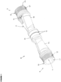
Figure 1 is a three-dimensional schematic showing a flowmeter in accordance with the present invention; -
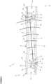
Figure 2 is a cross-sectional view of the flowmeter shown inFigure 1 ; -
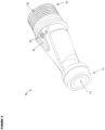
Figure 3 is a three-dimensional cross-sectional view of the flowmeter shown inFigures 1 and2 ; -
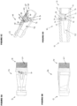
Figure 4 is a three-dimensional schematic of a part of the flowmeter shown inFigures 1 to 3 ; -
Figures 5a to 5d are top, side and cross-sectional views of the part of the flowmeter shown inFigure 4 ; -
Figure 6 is a three-dimensional schematic of a flowmeter in a housing in accordance with the invention; and -
Figure 7 is a three-dimensional cross-sectional view of the flowmeter and housing shown inFigure 6 . - Referring now to the drawings,
reference numeral 10 refers generally to a flowmeter in accordance with the present invention. Theflowmeter 10 includes abody 12 defining apassageway 14 for allowing fluid to flow therethrough and asensing arrangement 16 which extends substantially inwardly from opposingend regions 18 of thepassageway 14 for sensing a flow of fluid through thepassageway 14 along anaxis 20 which is substantially parallel thereto. - The
body 12 defines inlet andoutlet portions passageway 14 and anintermediate portion 26 between the inlet andoutlet portions outlet portions central axis 28 of theintermediate portion 26 is offset relativecentral axes 30 of the inlet andoutlet portions central axis 28 of theintermediate portion 26 is offset an angle in the range of 2 degrees and 6 degrees, typically being 3.8 degrees, relative thecentral axes 30 of the inlet andoutlet portions passageway 14 tapers generally from the outlet andinlet portions intermediate portion 26 to encourage laminar flow therethrough. -
Guide formations 32 are provided which extend into thepassageway 14 for guiding the flow of fluid therethrough and encouraging laminar flow of the fluid. Theguide formations 32 are sized, shaped and configured to guide the flow of fluid along a generally wave-like path through theintermediate portion 26 during an operative fluid flow condition wherein fluid is flowing through thepassageway 14. Theguide formations 32 are located diametrically opposite each other. Further, theguide formations 32 are shaped to form reducedflow zones 34 in the vicinity thereof during the operative fluid flow condition, the reducedflow zones 34 typically being formed towards theend regions 18 of theintermediate zone 26 between theguide formations 32. It is to be appreciated that the reducedflow zone 34 improves accuracy of thesensing arrangement 16 by reducing turbulent flow, noise, cavitation and the formation of eddy currents around theguide formations 32 in use. - The
guide formations 32 definesensor housings 36 for housing sensors in the form oftransceivers 38 of thesensing arrangement 16. Thesensor housings 36 may comprise a mountingmember 40 for mounting atransceiver 38 thereon and aclosure member 42 for closing aninside region 44 defined by theguide formation 32. The mountingmembers 40 of eachguide formation 32 are orientated relative thepassageway 14 such thattransceivers 38 mounted thereon face each other along theintermediate portion 26 of thepassageway 14. Theclosure member 42 is configured to close and seal theinside region 44 defined by thehousing 36 and inhibit the ingress of fluid into theinside region 44 during the operative fluid flow condition. - The
body 12 comprises a pair ofhollow members 46 which definepassages 48 which taper from oneend region 50 towards an opposingend region 52 thereof. The pair ofhollow members 46 are connected via opposingend regions 52 thereof during an operative aligned condition. The pair ofhollow members 46 are substantially identical in shape and size. A sealing member in the form of an O-ring 54 is provided for sealing a fit between thehollow members 46 during an operative aligned condition. Anaperture 56 is defined in awall 58 of eachhollow member 46 which extends into theinside region 44 of thesensor housing 36 for allowingwiring 60 to be connected to thetransceivers 38 in order to provide power thereto. - The
transceivers 38 are arranged in electrical communication with a processor (not shown) which is configured to process signals passing between thetransceivers 38 during the operative fluid flow condition, the processor (not shown) is configured to calculate a mass or volume flow rate of fluid flowing through thepassageway 14, typically being based on a time of flight measurement of the signals passing between thetransceivers 38. Thetransceivers 38 are configured to send signals between each other every 1 to 4 seconds, typically being every 2 seconds. Thetransceivers 38 can be configured to send signals between each other at a frequency in the range of 0.25Hz to 100Hz. Thetransceivers 38 are in the form of piezoelectric transceivers. Thepiezoelectric transceivers 38 are configured to vibrate when subject to a potential difference. In particular, thepiezoelectric transceivers 38 are configured to vibrate at any suitable frequency, preferably vibrating at a frequency so as to produce ultrasonic sound waves in the range of 20kHz and 10MHz, typically being 1MHz. - Connecting
members 62 having threaded outer profiles extend from thebody 12, typically extending away from thebody 12 in the region of the inlet andoutlet portions body 12 to be connected in-line with a water supply. - A housing 66 is provided for housing the
body 12, processor (not shown) and a power source (not shown) in use. The housing 66 includes a first portion 68 for housing thebody 12 and asecond portion 70 for housing the power source (not shown) for thetransceivers 38 and the processor (not shown). The housing 66 has a generally rectangular form, typically resembling a generally rectangular prism. The housing 66 includes a pair ofopenings 72 defined towards opposingend regions 74 thereof, theopenings 72 typically leading to the first portion 68 of the housing 66 for receiving correspondinghollow members 46 complementally therein. - A locating formation in the form of a slot and key arrangement 76 is provided for locating and guiding the
hollow members 46 into the operative aligned condition while being received by the first portion 68 of the housing 66. Slots 76.1 are typically defined on inner walls 78 of the housing 66 and key-like protrusions 76.2 are defined on an outer surface 80 of thehollow members 46. - Retaining
members 82 are provided for retaining thehollow members 46 within the housing 66, particularly in the operative aligned condition. The retainingmembers 82 are sized, shaped and configured to be interposed between the outer surface 80 of thehollow member 46 and a wall of anopening 72 of the housing 66. In particular, the retainingmembers 82 have a generally ring shape and are dimensioned to form a friction fit between thehollow member 46 and the wall 84 of theopening 72. It is to be appreciated that the retainingmember 82 is friction welded into position between thehollow member 46 and the wall 84 of theopening 72. - The
body 12,sensor housings 36 and housing 66 is manufactured form suitable synthetic plastics material, typically being manufactured from a thermoplastic of the group including acrylic, polypropylene, polystyrene, polyethylene, polyphenylene, polyaryletherketone and polyvinylchloride, typically being polyphenylene sulphide having product code Ryton R-7-120BL and manufactured by Solvay™. - It is, of course, to be appreciated that the flowmeter in accordance with the invention is not limited to the precise constructional and functional details as hereinbefore described with reference to the accompanying drawings and which may be varied as desired. The invention is defined by the appended claims.
Claims (14)
- A flowmeter (10) which includes: -a body (12) defining a passageway (14) for allowing fluid to flow therethrough, the passageway (14) having inlet and outlet portions (22) and (24) arranged at opposing end regions (18) of an intermediate portion (26) of the passageway (14), which intermediate portion (26) is arranged at an angle relative to central axes (30) of the inlet and outlet portions (22) and (24);a sensing arrangement (16) including a pair of sensors (38) extending substantially inwardly from opposing end regions (18) of the intermediate portion (26) for sensing a flow of fluid therebetween ; characterised in that:the intermediate portion (26) has a reduced cross-sectional area compared to the inlet and outlet portions (22) and (24), andthe sensing arrangement (16) extends along an axis which is substantially parallel to the intermediate portion (26).
- A flowmeter (10) as claimed in claim 1 wherein a central axis (28) of the intermediate portion is arranged at an angle in the range of 2 degrees to 6 degrees relative central axes (30) of the inlet and outlet portions (22) and (24).
- A flowmeter (10) as claimed in any one or more of the preceding claims wherein guide formations (32) are provided which extend into the passageway (14) for guiding the flow of fluid therethrough and encouraging laminar flow of the fluid wherein the guide formations (32) are sized, shaped and configured to guide the flow of fluid along a generally wave-like, undulating or arcuate path through the intermediate portion during an operative fluid flow condition.
- A flowmeter (10) as claimed in claim 3 wherein the guide formations (32) are located diametrically opposite each other and are shaped to form reduced flow zones (34) in the vicinity thereof during the operative fluid flow condition, wherein the reduced flow zones (34) are formed towards the end regions (18) of the intermediate portion (26) between the guide formations (32).
- A flowmeter (10) as claimed in claim 3 or 4 wherein the guide formations (32) define sensor housings (36) for housing the sensors (38) of the sensing arrangement (16), wherein the sensor housings (36) comprise a mounting member (40) for mounting a sensor (38) of the sensing arrangement (16) thereon and a closure member (42) for closing an inside region (44) defined by the guide formation (32), wherein the mounting members (40) of each guide formation (32) are orientated relative the passageway (14) such that the sensors (38) mounted thereon face each other along the intermediate portion (26) of the passageway (14) and wherein the closure member (42) is configured to close and seal the inside region (44) defined by the sensor housing (36) and inhibit the ingress of fluid into the inside region (44) during the operative fluid flow condition.
- A flowmeter (10) as claimed in any one or more of the preceding claims wherein the body (12) comprises a pair of hollow members (46) which define passages (48) which taper from one end region (50) towards an opposing end region (52) thereof, wherein the pair of hollow members (46) are substantially identical in shape and size.
- A flowmeter (10) as claimed in claim 6 wherein the pair of hollow members (46) are connected via opposing end regions (52) thereof during an operative aligned condition.
- A flowmeter (10) as claimed in claim 6 or 7 wherein a sealing member (54) is provided for sealing a fit between the hollow members (46) during the operative aligned condition.
- A flowmeter (10) as claimed in any one or more of the claims 6 to 8 wherein an aperture (56) is defined in a wall (58) of each hollow member (46) which extends into an inside region (44) thereof, for allowing wiring (60) to be connected to sensors (38) of the sensing arrangement (16) in order to provide power thereto.
- A flowmeter (10) as claimed in any one or more of the preceding claims wherein the sensors (38) of the sensing arrangement (16) are in the form of a pair of transceivers (38) which are housed within sensor housings (36) and wherein the transceivers (38) are arranged in electrical communication with a processor which is configured to process signals passing between the transceivers (38) during the operative fluid flow condition and to calculate a volume flow rate and a mass flow rate of fluid flowing through the passageway (14).
- A flowmeter (10) as claimed in claim 10 wherein the transceivers (38) are in the form of piezoelectric transceivers.
- A flowmeter (10) as claimed in any one or more of the preceding claims wherein connecting members (62) having threaded outer profiles extend from the body (12) for allowing the body (12) to be connected in-line with a water supply.
- A flowmeter (10) as claimed in any one or more of the preceding claims wherein a housing (66) is provided for housing the body (12), processor and a power source in use.
- A flowmeter (10) as claimed in any one or more of the preceding claims wherein the body (12) and housing (66) are manufactured from any one of the group of thermoplastics including acrylic, polypropylene, polystyrene, polyethylene, polyphenylene, polyaryletherketone and polyvinylchloride.
Applications Claiming Priority (2)
| Application Number | Priority Date | Filing Date | Title |
|---|---|---|---|
| ZA201706449 | 2017-12-03 | ||
| PCT/ZA2018/050062 WO2019109113A1 (en) | 2017-12-03 | 2018-12-03 | A flowmeter |
Publications (3)
| Publication Number | Publication Date |
|---|---|
| EP3717873A1 EP3717873A1 (en) | 2020-10-07 |
| EP3717873B1 true EP3717873B1 (en) | 2024-05-22 |
| EP3717873C0 EP3717873C0 (en) | 2024-05-22 |
Family
ID=65036915
Family Applications (1)
| Application Number | Title | Priority Date | Filing Date |
|---|---|---|---|
| EP18836584.5A Active EP3717873B1 (en) | 2017-12-03 | 2018-12-03 | A flowmeter |
Country Status (4)
| Country | Link |
|---|---|
| US (1) | US11473949B2 (en) |
| EP (1) | EP3717873B1 (en) |
| CN (1) | CN111670342B (en) |
| WO (1) | WO2019109113A1 (en) |
Citations (2)
| Publication number | Priority date | Publication date | Assignee | Title |
|---|---|---|---|---|
| US20110088483A1 (en) * | 2008-04-21 | 2011-04-21 | Mib Gmbh Messtechnik Und Industrieberatung | Ultrasonic measuring arrangement |
| WO2013157990A1 (en) * | 2012-04-17 | 2013-10-24 | Общество С Ограниченной Ответственностью "Научно-Производственное Предприятие "Уралтехнология" | Ultrasonic flow meter |
Family Cites Families (12)
| Publication number | Priority date | Publication date | Assignee | Title |
|---|---|---|---|---|
| US3771117A (en) * | 1972-03-01 | 1973-11-06 | Westinghouse Electric Corp | Transducer installation |
| NZ243293A (en) | 1991-06-25 | 1995-03-28 | Commw Scient Ind Res Org | Fluid flow meter: time of travel of acoustic wave packet through fluid |
| WO1997021985A1 (en) * | 1995-12-13 | 1997-06-19 | Matsushita Electric Industrial Co., Ltd. | Ultrasonic flowmeter and ultrasonic generator/detector |
| US8214168B2 (en) * | 2004-09-07 | 2012-07-03 | Transonic Systems, Inc. | Noninvasive testing of a material intermediate spaced walls |
| DE102008055164A1 (en) * | 2008-12-29 | 2010-07-01 | Endress + Hauser Flowtec Ag | Measuring system for determining and / or monitoring the flow of a measuring medium through the measuring tube by means of ultrasound |
| DE102009045020A1 (en) * | 2009-09-25 | 2011-03-31 | Robert Bosch Gmbh | Flow meter for use in a flowing fluid medium |
| US8181534B2 (en) * | 2010-01-06 | 2012-05-22 | Daniel Measurement And Control, Inc. | Ultrasonic flow meter with transducer assembly, and method of manufacturing the same while maintaining the radial position of the piezoelectric element |
| EP2759808B1 (en) * | 2013-01-29 | 2019-11-20 | Itron Global SARL | Ultrasonic flow meter |
| DE102013114475B4 (en) | 2013-12-19 | 2021-04-08 | Sick Ag | Ultrasonic measuring device and method for determining the flow velocity |
| CA2952064C (en) * | 2014-06-10 | 2020-04-07 | Soneter, Inc. | Sensor assembly |
| DE102014118187A1 (en) * | 2014-12-09 | 2016-06-09 | Endress + Hauser Flowtec Ag | Ultrasonic flowmeter |
| FR3047068B1 (en) * | 2016-01-25 | 2019-07-19 | Integra Metering Sas | DEVICE FOR MOUNTING AN ULTRASOUND TRANSDUCER AND FLOW METER EQUIPPED WITH SUCH A DEVICE |
-
2018
- 2018-12-03 CN CN201880088383.9A patent/CN111670342B/en active Active
- 2018-12-03 WO PCT/ZA2018/050062 patent/WO2019109113A1/en unknown
- 2018-12-03 US US16/769,136 patent/US11473949B2/en active Active
- 2018-12-03 EP EP18836584.5A patent/EP3717873B1/en active Active
Patent Citations (2)
| Publication number | Priority date | Publication date | Assignee | Title |
|---|---|---|---|---|
| US20110088483A1 (en) * | 2008-04-21 | 2011-04-21 | Mib Gmbh Messtechnik Und Industrieberatung | Ultrasonic measuring arrangement |
| WO2013157990A1 (en) * | 2012-04-17 | 2013-10-24 | Общество С Ограниченной Ответственностью "Научно-Производственное Предприятие "Уралтехнология" | Ultrasonic flow meter |
Also Published As
| Publication number | Publication date |
|---|---|
| WO2019109113A1 (en) | 2019-06-06 |
| US11473949B2 (en) | 2022-10-18 |
| EP3717873A1 (en) | 2020-10-07 |
| US20210231479A1 (en) | 2021-07-29 |
| EP3717873C0 (en) | 2024-05-22 |
| CN111670342B (en) | 2023-11-24 |
| CN111670342A (en) | 2020-09-15 |
Similar Documents
| Publication | Publication Date | Title |
|---|---|---|
| US9297681B2 (en) | Ultrasonic measurement apparatus having transducers arranged within a bulge of the channel wall protruding into the flow channel | |
| EP2639560B1 (en) | Ultrasonic flow rate measurement device | |
| CN109477742B (en) | Flowmeter with measuring channel | |
| US8091435B2 (en) | Ultrasonic measuring arrangement | |
| US10527476B2 (en) | Ultrasonic flow meter having a main channel and at least one secondary channel | |
| US9372106B2 (en) | Non-circular flowmeter | |
| JP5984094B2 (en) | Ultrasonic flow meter | |
| AU2019278790B2 (en) | Ultrasonic meter | |
| US20080271544A1 (en) | Plastic Ultrasonic Measurement Section and Corresponding Measurement Method | |
| CN108603776B (en) | Assembly device for assembling an ultrasonic transducer and flowmeter equipped with such a device | |
| US9297679B2 (en) | Flowmeter with a flow conditioner formed by a protrusion having restriction provided upstream of the measurement section | |
| CN105387898B (en) | Flowmeter with the measure plug-in being inserted into shell | |
| US11573107B2 (en) | Hydraulic system for ultrasonic flow measurement using direct acoustic path approach | |
| US20190107419A1 (en) | Hydraulic system for ultrasonic flow measurement using reflective acoustic path approach | |
| CN105510627A (en) | Flow measuring device for measuring parameter of flow formed from fluid | |
| EP3798583B1 (en) | Transducer support mounting for an ultrasonic flow meter and ultrasonic flow meter | |
| EP3717873B1 (en) | A flowmeter | |
| JPH10142017A (en) | Karman's vortex flow meter | |
| CN109959429B (en) | Ultrasonic detector and detection equipment | |
| WO2008033035A1 (en) | Arrangement for measuring fluid flow velocity | |
| WO2013157990A1 (en) | Ultrasonic flow meter | |
| US20220316932A1 (en) | Measuring device for determining the flow of a fluid flowing through a pipe section | |
| RU2672815C1 (en) | Measuring flow in ultrasound | |
| EP3574290B1 (en) | Insert vortex flowmeter element | |
| JP2009156711A (en) | Ultrasonic flowmeter |
Legal Events
| Date | Code | Title | Description |
|---|---|---|---|
| STAA | Information on the status of an ep patent application or granted ep patent |
Free format text: STATUS: UNKNOWN |
|
| STAA | Information on the status of an ep patent application or granted ep patent |
Free format text: STATUS: THE INTERNATIONAL PUBLICATION HAS BEEN MADE |
|
| PUAI | Public reference made under article 153(3) epc to a published international application that has entered the european phase |
Free format text: ORIGINAL CODE: 0009012 |
|
| STAA | Information on the status of an ep patent application or granted ep patent |
Free format text: STATUS: REQUEST FOR EXAMINATION WAS MADE |
|
| 17P | Request for examination filed |
Effective date: 20200701 |
|
| AK | Designated contracting states |
Kind code of ref document: A1 Designated state(s): AL AT BE BG CH CY CZ DE DK EE ES FI FR GB GR HR HU IE IS IT LI LT LU LV MC MK MT NL NO PL PT RO RS SE SI SK SM TR |
|
| AX | Request for extension of the european patent |
Extension state: BA ME |
|
| DAV | Request for validation of the european patent (deleted) | ||
| DAX | Request for extension of the european patent (deleted) | ||
| STAA | Information on the status of an ep patent application or granted ep patent |
Free format text: STATUS: EXAMINATION IS IN PROGRESS |
|
| 17Q | First examination report despatched |
Effective date: 20220527 |
|
| GRAP | Despatch of communication of intention to grant a patent |
Free format text: ORIGINAL CODE: EPIDOSNIGR1 |
|
| STAA | Information on the status of an ep patent application or granted ep patent |
Free format text: STATUS: GRANT OF PATENT IS INTENDED |
|
| RIC1 | Information provided on ipc code assigned before grant |
Ipc: G01F 15/18 20060101ALN20231130BHEP Ipc: G01F 1/667 20220101ALI20231130BHEP Ipc: G01F 1/66 20060101AFI20231130BHEP |
|
| RIC1 | Information provided on ipc code assigned before grant |
Ipc: G01F 15/18 20060101ALN20231204BHEP Ipc: G01F 1/667 20220101ALI20231204BHEP Ipc: G01F 1/66 20060101AFI20231204BHEP |
|
| INTG | Intention to grant announced |
Effective date: 20231222 |
|
| RIC1 | Information provided on ipc code assigned before grant |
Ipc: G01F 15/18 20060101ALN20231214BHEP Ipc: G01F 1/667 20220101ALI20231214BHEP Ipc: G01F 1/66 20060101AFI20231214BHEP |
|
| GRAS | Grant fee paid |
Free format text: ORIGINAL CODE: EPIDOSNIGR3 |
|
| GRAA | (expected) grant |
Free format text: ORIGINAL CODE: 0009210 |
|
| STAA | Information on the status of an ep patent application or granted ep patent |
Free format text: STATUS: THE PATENT HAS BEEN GRANTED |
|
| AK | Designated contracting states |
Kind code of ref document: B1 Designated state(s): AL AT BE BG CH CY CZ DE DK EE ES FI FR GB GR HR HU IE IS IT LI LT LU LV MC MK MT NL NO PL PT RO RS SE SI SK SM TR |
|
| REG | Reference to a national code |
Ref country code: GB Ref legal event code: FG4D |
|
| REG | Reference to a national code |
Ref country code: CH Ref legal event code: EP |
|
| REG | Reference to a national code |
Ref country code: DE Ref legal event code: R096 Ref document number: 602018069863 Country of ref document: DE |
|
| REG | Reference to a national code |
Ref country code: IE Ref legal event code: FG4D |
|
| U01 | Request for unitary effect filed |
Effective date: 20240522 |
|
| U07 | Unitary effect registered |
Designated state(s): AT BE BG DE DK EE FI FR IT LT LU LV MT NL PT SE SI Effective date: 20240527 |