EP2103912A1 - Flow measurement with ultrasound - Google Patents
Flow measurement with ultrasound Download PDFInfo
- Publication number
- EP2103912A1 EP2103912A1 EP08102712A EP08102712A EP2103912A1 EP 2103912 A1 EP2103912 A1 EP 2103912A1 EP 08102712 A EP08102712 A EP 08102712A EP 08102712 A EP08102712 A EP 08102712A EP 2103912 A1 EP2103912 A1 EP 2103912A1
- Authority
- EP
- European Patent Office
- Prior art keywords
- flow
- ultrasound
- measuring
- ultrasonic
- measurement
- Prior art date
- Legal status (The legal status is an assumption and is not a legal conclusion. Google has not performed a legal analysis and makes no representation as to the accuracy of the status listed.)
- Granted
Links
- 238000005259 measurement Methods 0.000 title claims description 49
- 238000002604 ultrasonography Methods 0.000 title claims description 33
- 239000012530 fluid Substances 0.000 claims abstract description 20
- 238000000034 method Methods 0.000 claims abstract description 12
- 230000001419 dependent effect Effects 0.000 claims description 3
- 238000006073 displacement reaction Methods 0.000 claims 1
- 239000007789 gas Substances 0.000 abstract description 12
- 230000000694 effects Effects 0.000 description 9
- 230000008901 benefit Effects 0.000 description 4
- 230000005855 radiation Effects 0.000 description 4
- 230000006870 function Effects 0.000 description 3
- 239000012528 membrane Substances 0.000 description 3
- 241000196324 Embryophyta Species 0.000 description 2
- 230000002411 adverse Effects 0.000 description 2
- 230000015572 biosynthetic process Effects 0.000 description 2
- 230000008859 change Effects 0.000 description 2
- 238000010586 diagram Methods 0.000 description 2
- 238000005516 engineering process Methods 0.000 description 2
- 230000001771 impaired effect Effects 0.000 description 2
- 230000006872 improvement Effects 0.000 description 2
- 238000004519 manufacturing process Methods 0.000 description 2
- 230000000644 propagated effect Effects 0.000 description 2
- 230000001629 suppression Effects 0.000 description 2
- 238000013519 translation Methods 0.000 description 2
- UGFAIRIUMAVXCW-UHFFFAOYSA-N Carbon monoxide Chemical compound [O+]#[C-] UGFAIRIUMAVXCW-UHFFFAOYSA-N 0.000 description 1
- 241001295925 Gegenes Species 0.000 description 1
- 235000010678 Paulownia tomentosa Nutrition 0.000 description 1
- 240000002834 Paulownia tomentosa Species 0.000 description 1
- 238000004458 analytical method Methods 0.000 description 1
- 238000013459 approach Methods 0.000 description 1
- 230000005540 biological transmission Effects 0.000 description 1
- 230000000052 comparative effect Effects 0.000 description 1
- 238000009795 derivation Methods 0.000 description 1
- 230000006866 deterioration Effects 0.000 description 1
- 238000011161 development Methods 0.000 description 1
- 238000011156 evaluation Methods 0.000 description 1
- 239000003546 flue gas Substances 0.000 description 1
- 238000003780 insertion Methods 0.000 description 1
- 230000037431 insertion Effects 0.000 description 1
- 230000003993 interaction Effects 0.000 description 1
- 238000012423 maintenance Methods 0.000 description 1
- 238000000691 measurement method Methods 0.000 description 1
- 238000005457 optimization Methods 0.000 description 1
- 230000008092 positive effect Effects 0.000 description 1
- 230000002265 prevention Effects 0.000 description 1
- 238000011160 research Methods 0.000 description 1
- 238000004092 self-diagnosis Methods 0.000 description 1
- 230000002123 temporal effect Effects 0.000 description 1
- 238000003466 welding Methods 0.000 description 1
Images


Classifications
-
- G—PHYSICS
- G01—MEASURING; TESTING
- G01F—MEASURING VOLUME, VOLUME FLOW, MASS FLOW OR LIQUID LEVEL; METERING BY VOLUME
- G01F1/00—Measuring the volume flow or mass flow of fluid or fluent solid material wherein the fluid passes through a meter in a continuous flow
- G01F1/66—Measuring the volume flow or mass flow of fluid or fluent solid material wherein the fluid passes through a meter in a continuous flow by measuring frequency, phase shift or propagation time of electromagnetic or other waves, e.g. using ultrasonic flowmeters
- G01F1/662—Constructional details
Abstract
Description
Die Erfindung betrifft eine Messvorrichtung und ein Verfahren für die Bestimmung einer Strömungsgeschwindigkeit und/oder eines Durchflusses eines in einer Leitung strömenden Fluids nach dem Oberbegriff von Anspruch 1 beziehungsweise 8.The invention relates to a measuring device and a method for determining a flow velocity and / or a flow rate of a fluid flowing in a line according to the preamble of claims 1 and 8, respectively.
Für die Messung von Fluidgeschwindigkeiten in Rohrleitungen und Kanälen kann die Ultraschallmesstechnik nach dem Differenzlaufzeitverfahren eingesetzt werden. Dabei werden Ultraschallpulse von einem Paar Ultraschallwandler ausgesandt und empfangen, die einander gegenüber an einer Wandung der Leitung angeordnet sind und aus der Laufzeitdifferenz zwischen einem Messpfad mit der Strömung und dem Messpfad in Gegenrichtung entgegen der Strömung wird die Strömungsgeschwindigkeit bestimmt. In der Ultraschallmesstechnik herrscht häufig der Sprachgebrauch, die beiden Richtungen zusammenfassend als einen Messpfad zu bezeichnen. Da gerade bei hohen Geschwindigkeiten die Bedingungen mit und gegen die Strömungsgeschwindigkeit sich stark voneinander unterscheiden können, wird von diesem Sprachgebrauch gezielt abgewichen.For the measurement of fluid velocities in pipelines and channels, the ultrasonic measuring technique can be used according to the differential transit time method. In this case, ultrasonic pulses are emitted and received by a pair of ultrasonic transducers, which are arranged opposite each other on a wall of the conduit and from the transit time difference between a measuring path with the flow and the measuring path in the opposite direction against the flow, the flow rate is determined. In ultrasound measurement technology, it is often the language used to refer to the two directions in summary as a measuring path. Since especially at high speeds, the conditions with and against the flow velocity can differ greatly from one another, deliberately deviated from this usage.
Dieses bekannte Messprinzip ist in
- v: Strömungsgeschwindigkeit des Fluids in der Leitung
- L: Länge des Messpfades zwischen den beiden Ultraschallwandlern
- α: Winkel, unter dem die Ultraschallwandler senden und empfangen
- Q: Volumenstrom
- D: Durchmesser der Leitung
- tv: Laufzeit des Ultraschalls mit der Strömung
- tr: Laufzeit des Ultraschalls gegen die Strömung
- v: flow velocity of the fluid in the conduit
- L: length of the measuring path between the two ultrasonic transducers
- α: angle at which the ultrasonic transducers transmit and receive
- Q: flow rate
- D: diameter of the pipe
- t v : transit time of the ultrasound with the flow
- t r : transit time of the ultrasound against the flow
Daraus ergeben sich für die gesuchten Größen v und Q folgende Beziehungen: ![]()
![]()
![]()
![]()
Eine besonders anspruchsvolle Anwendung ist die Strömungsmessung von mit sehr hoher Geschwindigkeit in Leitungen bewegten Gasen. Ein Beispiel hierfür sind Flaregasleitungen, welche in petrochemischen Anlagen zu Fackeltürmen führen und in denen Restgase des Produktionsprozesses beziehungsweise im Störfall große Gasmengen mit hoher Geschwindigkeit aus der Anlage gebracht werden. Für derart hohe Strömungsgeschwindigkeiten eines Gases von 70 m/s und mehr ist die herkömmliche Ultraschallmessung nicht ohne Weiteres geeignet und führt zu nur unbefriedigend genauen Messergebnissen. Alternative Messverfahren sind aber im Gegensatz zur Ultraschallmessung abhängig von weiteren Größen wie Druck, Temperatur und Gaszusammensetzung.A particularly demanding application is the flow measurement of gases moving at very high speed in pipes. An example of this are flue gas lines, which lead to torch towers in petrochemical plants and in which residual gases of the production process or, in the event of a fault, large quantities of gas are brought out of the plant at high speed. For such high flow velocities of a gas of 70 m / s and more, the conventional ultrasonic measurement is not readily suitable and leads to only unsatisfactorily accurate measurement results. However, in contrast to ultrasound measurement, alternative measuring methods are dependent on other parameters such as pressure, temperature and gas composition.
Eine im Stand der Technik eingesetzte Maßnahme zur Verbesserung der Messergebnisse mit Ultraschall ist, beide Ultraschallwandler um einen zusätzlichen Vorhaltewinkel von einigen Grad gegen die Strömung anzustellen, so dass also ausgesandter Ultraschall bei idealen geraden Messpfaden das jeweilige Gegenüber verfehlen würde und wegen der Verwehung jeweils mit der Strömung zu dem gegenüberliegenden Ultraschallempfänger getrieben wird. Damit sollen Effekte der hohen Gasgeschwindigkeit ausgeglichen werden. Zudem werden zur Kompensation von Strömungseffekten aufwändige Signalauswertungen vorgenommen. Diese Maßnahme genügt jedoch nicht, zufriedenstellende Messgenauigkeit erreichen, weil die eigentliche Ursache der Störungen nicht erkannt und damit auch nicht kompensiert ist.A measure used in the prior art to improve the measurement results with ultrasound is to make both ultrasonic transducers an additional lead angle of a few degrees against the flow, so that emitted ultrasound with ideal straight measurement paths would miss the respective counterpart and because of the drift respectively with the Flow is driven to the opposite ultrasonic receiver. This should compensate for effects of high gas velocity. In addition, complex signal evaluations are made to compensate for flow effects. However, this measure is not sufficient to achieve satisfactory measurement accuracy, because the actual cause of the disturbances is not recognized and therefore not compensated.
Aus der
Es ist daher Aufgabe der Erfindung, die Bestimmung einer Strömungsgeschwindigkeit eines Fluids mit Ultraschallwandlern insbesondere bei sehr hohen Strömungsgeschwindigkeiten zu verbessern.It is therefore an object of the invention to improve the determination of a flow velocity of a fluid with ultrasonic transducers, in particular at very high flow velocities.
Diese Aufgabe wird durch eine Messvorrichtung gemäß Anspruch 1 und ein Messverfahren gemäß Anspruch 8 gelöst.This object is achieved by a measuring device according to claim 1 and a measuring method according to claim 8.
Die erfindungsgemäße Lösung geht von der Erkenntnis aus, dass der wesentliche Grund für schlechte Messwerte bei hohen Strömungsgeschwindigkeiten Abrisswirbel an den in den Innenraum der Leitung hineinragenden Kanten der Ultraschallwandler sind, welche eine erhebliche Lärmbelastung verursachen, welche Ultraschallsignale stören kann. Dadurch entsteht eine starke Signalverzerrung und damit Verschlechterung des Signal/Rauschverhältnisses, wenn ein Signalpaket durch einen solchen Abrisswirbel zu dem gegenüberliegenden Ultraschallwandler gesandt wird. Zusätzlich wird das abgestrahlte Signal auch noch durch die Strömung verweht. Daher ist die Grundidee der Erfindung, Abrisswirbel zu unterdrücken.The solution according to the invention is based on the recognition that the essential reason for poor measured values at high flow velocities are demolition vortices on the edges of the ultrasonic transducers projecting into the interior of the conduit, which cause considerable noise pollution, which can disturb ultrasonic signals. This results in a strong signal distortion and thus deterioration of the signal / noise ratio when a signal packet is sent through such a demolition vortex to the opposite ultrasonic transducer. In addition, the radiated signal is also blown by the flow. Therefore, the basic idea of the invention is to suppress demolition vertebrae.
Die Erfindung hat den Vorteil, die Beeinflussung des Abstrahlverhaltens und besonders eine Vergrößerung des Abstrahlwinkels der Schallkeule durch Abrisswirbel zu reduzieren, welche auch durch den einleitend beschriebenen Vorhaltewinkel nicht in hinreichendem Maße kompensiert werden könnten. Indem Abrisswirbel unterdrückt werden, erhöht sich die Signalqualität, weil die Wellenfront des Signals erhalten bleibt. Die Wellenfront trifft erfindungsgemäß trotz der hohen Strömungsgeschwindigkeit unter annähernd 90° auf die Membran des empfangenden Ultraschallwandlers, womit der Krafteintrag und die Signalamplitude hoch bleiben.The invention has the advantage of reducing the influence of the radiation behavior and especially an increase in the emission angle of the sound beam by demolition vortices, which could not be compensated to a sufficient extent by the Vorhaltewinkel described in the introduction. By suppressing demolition, the signal quality increases because the wavefront of the signal is preserved. The wavefront according to the invention meets in spite of the high flow rate under approximately 90 ° to the membrane of the receiving ultrasonic transducer, whereby the force input and the signal amplitude remain high.
Damit kann eine besonders bei hohen Strömungsgeschwindigkeiten verbesserte Messgenauigkeit erreicht werden, die nicht oder zumindest deutlich weniger von strömungstechnischen Störeffekten beeinträchtigt ist. Die Vorteile der Ultraschallmessung gegenüber anderen Verfahren, nämlich Unabhängigkeit von Druck, Temperatur und Gaszusammensetzung und weiterhin hohe Präzision, Wartungsfreiheit, Möglichkeiten der Selbstdiagnose und Vermeidung eines Druckabfalls durch die Messung können somit auch bei den genannten Anwendungen mit sehr hohen Strömungsgeschwindigkeiten ausgenutzt werden. Vergleichende Messungen zeigen, dass der Lärmpegel (Störpegel am Ultraschallwandler) sich auf die Hälfte und der Verwehungswinkel der Schallkeule um ca. 1/3 verringert.Thus, an improved especially at high flow rates measurement accuracy can be achieved, which is not or at least significantly less affected by aerodynamic disruptive effects. The advantages of ultrasonic measurement over other methods, namely independence of pressure, temperature and gas composition, and furthermore high precision, freedom from maintenance, possibilities of self-diagnosis and avoidance of pressure drop through the measurement can thus be exploited even in the applications mentioned with very high flow velocities. Comparative measurements show that the noise level (noise level at the ultrasonic transducer) is reduced by half and the drift angle of the sound lobe by about 1/3.
Die Leitung ist vorzugsweise eine Rohrleitung mit zylindrischem oder rechteckigem Querschnitt, die für hohe Strömungsgeschwindigkeiten von zumindest 40 m/s oder sogar von zumindest 70 m/s ausgebildet und insbesondere eine Flaregasleitung ist. Die erfindungsgemäße Vermeidung von Abrisswirbeln erschließt der Ultraschallmessung diese neuen Anwendungen. Natürlich sind Rohrleitungen mit anderem Querschnitt von der Erfindung umfasst, sofern darin hohe Strömungsgeschwindigkeiten ohne allzu große Turbulenzen erreicht werden können.The conduit is preferably a conduit of cylindrical or rectangular cross-section, which is designed for high flow velocities of at least 40 m / s or even at least 70 m / s, and is in particular a flare gas conduit. The prevention of demolition vortices according to the invention opens up the ultrasonic measurement of these new applications. Of course, pipelines of a different cross-section are included in the invention, provided that high flow velocities can be achieved therein without too much turbulence.
Bevorzugt sind zusätzliche Ultraschallwandler vorgesehen, welche dafür ausgebildet sind, die Strömungsgeschwindigkeit und/oder den Durchfluss auf mindestens einem weiteren Messpfad zu bestimmen. Diese zusätzlichen Ultraschallwandler weisen dabei vorzugsweise ebenfalls die erfindungsgemäße strömungsoptimierte Kontur auf. Durch zusätzliche Messpfade kann bei gestörten Strömungen ein besseres Maß für den Volumenstrom gefunden werden, welches nicht oder weniger durch lokale Geschwindigkeitsunterschiede der Strömung verfälscht ist. Dabei sind zwei Fälle zu unterscheiden: Entweder wird ein zusätzlicher Empfänger etwas weiter stromabwärts eingesetzt, welcher einen stärker verwehten Anteil des Messsignals aufnimmt und damit eigentlich noch dem ursprünglichen Paar von Messpfaden zugehört, oder es werden ein oder mehrere zusätzliche Paare von Ultraschallwandlern eingesetzt, die ein klassisches Mehrpfadmesssystem bilden. Die beiden Fälle lassen sich auch vereinen, so dass dann in einem klassischen Mehrpfadsystem jeweils mehrere Empfänger den verwehten Anteil zusätzlich aufnehmen.Preferably, additional ultrasonic transducers are provided, which are designed to determine the flow velocity and / or the flow on at least one further measurement path. These additional ultrasonic transducers preferably also have the flow-optimized contour according to the invention. Additional measurement paths can be used to find a better measure of the volume flow in disturbed flows, which is not or is falsified by local speed differences of the flow. There are two cases to be distinguished: Either an additional receiver is used somewhat further downstream, which absorbs a more blown portion of the measurement signal and thus actually still belongs to the original pair of measurement paths, or one or more additional pairs of ultrasonic transducers are used form classic multipath measuring system. The two cases can also be combined, so that then in a classic multi-path system in each case several recipients absorb the blown share in addition.
Die Ultraschallwandler sind vorteilhafterweise an einer Wandung der Leitung angeordnet, insbesondere in jeweils einem senkrecht zu der Leitung angeordneten Stutzen montiert oder angeschweißt und ragen zumindest mit einem Teilbereich in den von dem Fluid durchströmten Innenraum hinein, wobei insbesondere ein den jeweiligen Ultraschallwandler umgebender Leitungsteilbereich der Wandung gemeinsam mit dem in den Innenraum ragenden Teilbereich des Ultraschallwandlers die strömungsoptimierte Kontur bildet. Zwar wäre grundsätzlich die Verwirbelung an den Ultraschallwandlern geringer, wenn sie in einen Stutzen der Wandung zurückgezogen würden. Dabei entstehen aber problematische Wandreflexionen und eine Veränderung der Abstrahlcharakteristik. Durch die erfindungsgemäße strömungsoptimierte Kontur ist es möglich, auf dieses Zurückziehen zu verzichten, ohne damit hohe Lärmstörungen an den Ultraschallwandlern zu verursachen und durch Hineinragen der Ultraschallwandler ein reflexionsfreies und in seiner Abstrahlcharakteristik erhaltenes Ultraschallsignal zu verwenden. Wenn die Bereiche der Wandung, welche die Ultraschallwandler umgeben, Teil der strömungsoptimierten Kontur sind, so können Abrisswirbel in einem noch stärker verbesserten Maße vermieden werden, weil der Strömung großflächigere und damit glattere Konturen angeboten werden können.The ultrasonic transducers are advantageously arranged on a wall of the conduit, in particular mounted in each case a perpendicular to the line arranged nozzle or welded and protrude at least with a partial area in the flowed through by the fluid interior, in particular a surrounding the respective ultrasonic transducer line portion of the wall together forms the flow-optimized contour with the protruding into the interior portion of the ultrasonic transducer. Although, in principle, the turbulence on the ultrasonic transducers would be lower if they were withdrawn into a connecting piece of the wall. However, problematic wall reflections and a change of the radiation characteristic arise. The flow-optimized contour according to the invention makes it possible to dispense with this retraction without causing high noise disturbances on the ultrasonic transducers and by using the ultrasound transducers to use a reflection-free ultrasound signal obtained in its emission characteristic. If the regions of the wall surrounding the ultrasonic transducers are part of the flow-optimized contour, demolition vortices can be avoided to an even more improved extent because the flow can be offered over a larger area and therefore smoother outlines.
Bevorzugt sind die Ultraschallwandler in einem Gehäuse untergebracht, welches die strömungsoptimierte Kontur aufweist, wobei das Gehäuse an zumindest einer Seite eine glatte, konvexe Außenkontur hat. Dieses Gehäuse kann auch größer sein als die eigentlichen Ultraschallwandler und ihre Membrane und es schafft so Freiheitsgrade der Translation und der Verkippung der Ultraschallwandler gegenüber ihrem Gehäuse, wie es die optimalen Messpfade fordern, ohne dabei die der Strömung angebotene Kontur zu verändern, welche durch das Gehäuse vorgegeben ist.The ultrasonic transducers are preferably accommodated in a housing which has the flow-optimized contour, wherein the housing has a smooth, convex outer contour on at least one side. This housing may also be larger than the actual ultrasonic transducers and their diaphragms and thus provides degrees of freedom of translation and tilt of the ultrasonic transducers with respect to their housing, as required by the optimum measurement paths, without altering the flow offered contour passing through the housing is predetermined.
Besonders bevorzugt ist das Gehäuse senkrecht in die Leitung eingesetzt und jeder Ultraschallwandler ist mit seiner Abstrahlfläche um einen Winkel verkippt, so dass der erste und der zweite Messpfad gegenüber einer Querschnittsebene der Leitung schräg verlaufen. Die Messpfade verlaufen damit schräg sowohl zur Strömungsrichtung wie zu einer Senkrechten zur Strömungsrichtung. Das senkrechte Einsetzen erleichtert die Montage und die Ausrichtung, denn ein schräges, stabiles Anschweißen der Stutzen vor Ort, um eine exakte Ausrichtung zu erzielen, erfordert einen erhöhten technischen Aufwand, ist kompliziert und fehlerbehaftet. Die Verkippung der Ultraschallwandler gegenüber dem Gehäuse ermöglicht die einfachere senkrechte Montage und gleichzeitig die freie, durch Messanforderungen vorgegebene Ausrichtung der Ultraschallwandler.Particularly preferably, the housing is inserted vertically into the conduit and each ultrasonic transducer is tilted with its emission surface at an angle, so that the first and the second measurement path with respect to a cross-sectional plane of the conduit are inclined. The measuring paths thus run obliquely both to the flow direction as well as to a perpendicular to the flow direction. The vertical insertion facilitates mounting and alignment, because an oblique, stable welding of the socket on site to achieve an exact alignment, requires increased technical complexity, is complicated and error-prone. The tilting of the ultrasonic transducer relative to the housing allows for easier vertical mounting and at the same time the free, predetermined by measurement requirements alignment of the ultrasonic transducer.
Der Verkippungswinkel kann dabei so gewählt sein, dass die Ultraschallwandler zueinander ausgerichtet sind, es kann aber auch ein zusätzlicher Vorhaltewinkel in Gegenrichtung der Strömung vorgesehen sein. Ohne Veränderung der strömungsoptimierten Außenkontur können die Ultraschallwandler so ausgerichtet werden, dass ihre Abstrahlrichtung namentlich gegenüber Verwehungen zu möglichst genauen Messergebnissen führt.The tilt angle can be chosen so that the ultrasonic transducers are aligned with each other, but it can also be provided an additional Vorhaltewinkel in the opposite direction of the flow. Without altering the flow-optimized outer contour, the ultrasound transducers can be aligned so that their direction of radiation, especially with respect to drifts, leads to the most accurate measurement results possible.
In vorteilhafter Weiterbildung sind der erste und der zweite Ultraschallwandler zueinander parallelverschoben angeordnet, so dass der erste Messpfad und der zweite Messpfad zueinander um einen Versatz in Strömungsrichtung beabstandet verlaufen. Dabei haben also die Schallachsen der einander gegenüberstehenden Ultraschallwandler zueinander den Versatz. Es hat sich nämlich gezeigt, dass die Qualität des Signals auf dem Messpfad gegen die Strömungsrichtung in besonders hohem Maße unter Abrisswirbel und Verwehungen leidet. Durch den Versatz trifft der Ultraschall auf diesem Messpfad den gegenüberliegenden Ultraschallwandler in verbesserter Weise. Zwar wird das Messergebnis auf dem Messpfad mit der Strömungsrichtung zugleich etwas beeinträchtigt, da dieser Messpfad zwangsläufig etwas schlechter auf den zugehörigen Ultraschallempfänger ausgerichtet ist. Da die Gesamtmessung als Laufzeitdifferenz von beiden Messpfaden abhängt, wird dieser geringe Verlust durch den Gewinn auf dem Messpfad gegen die Strömungsrichtung überkompensiert. Der Signal/Rauschabstand beispielsweise bei 80 m/s kann durch den Versatz um mindestens weitere 2 dB verbessert werden.In an advantageous development of the first and the second ultrasonic transducer are arranged parallel to each other in parallel, so that the first measuring path and the second measuring path to each other by an offset in the flow direction are spaced. In this case, therefore, the sound axes of the opposing ultrasonic transducers to each other have the offset. It has been shown that the quality of the signal on the measurement path against the flow direction suffers particularly severely under demolition and drift. Due to the offset, the ultrasound impinges on this measuring path the opposite ultrasonic transducer in an improved manner. Although the measurement result on the measuring path with the flow direction is at the same time somewhat impaired, since this measuring path is inevitably somewhat less well aligned with the associated ultrasonic receiver. Since the total measurement depends on the transit time difference of both measurement paths, this small loss is overcompensated by the gain on the measurement path against the flow direction. The signal-to-noise ratio, for example, at 80 m / s can be improved by the offset by at least another 2 dB.
Das erfindungsgemäße Verfahren kann auf ähnliche Weise weitergebildet werden und zeigt dabei ähnliche Vorteile. Derartige vorteilhafte Merkmale sind beispielhaft, aber nicht abschließend in den sich an die unabhängigen Ansprüche anschließenden Unteransprüchen beschrieben.The method according to the invention can be developed in a similar manner and shows similar advantages. Such advantageous features are described by way of example but not exhaustively in the subclaims following the independent claims.
Die Erfindung wird nachstehend auch hinsichtlich weiterer Merkmale und Vorteile beispielhaft anhand von Ausführungsformen und unter Bezug auf die beigefügte Zeichnung näher erläutert. Die Abbildungen der Zeichnung zeigen in:
- Fig. 1
- einen Längsschnitt durch eine Rohrleitung mit einer ersten Ausführungs- form einer erfindungsgemäßen Messvorrichtung;
- Fig. 2
- ein schematisches Blockschaltbild der erfindungsgemäßen Messvorrich- tung;
- Fig. 3
- einen Längsschnitt gemäß
Figur 1 zur Erläuterung der Entstehung und Auswirkung von Abrisswirbeln und Verwehungen; - Fig. 4
- einen Funktionsplot der theoretisch zu erwartenden Verwehungswinkel in Abhängigkeit von der Strömungsgeschwindigkeit;
- Fig. 5
- einen Längsschnitt gemäß
Figur 1 einer zweiten Ausführungsform einer erfindungsgemäßen Messvorrichtung mit einem Parallelversatz der Ultra- schallwandler; - Fig. 6
- einen Längsschnitt gemäß
Figur 1 einer dritten Ausführungsform einer er- findungsgemäßen Messvorrichtung mit zusätzlichen strömungsoptimierten Konturen der Rohrleitung; und - Fig. 7
- einen Längsschnitt durch eine Rohrleitung mit einer Messvorrichtung nach dem Stand der Technik zur Erläuterung eines Ultraschallmessverfahrens mittels einer Laufzeitdifferenz.
- Fig. 1
- a longitudinal section through a pipeline with a first embodiment of a measuring device according to the invention;
- Fig. 2
- a schematic block diagram of the measuring device according to the invention;
- Fig. 3
- a longitudinal section according to
FIG. 1 explaining the formation and effect of demolition and drifting; - Fig. 4
- a functional plot of the theoretically expected drift angles as a function of the flow velocity;
- Fig. 5
- a longitudinal section according to
FIG. 1 a second embodiment of a measuring device according to the invention with a parallel offset of the ultrasonic transducer; - Fig. 6
- a longitudinal section according to
FIG. 1 a third embodiment of an inventive measuring device with additional flow-optimized contours of the pipeline; and - Fig. 7
- a longitudinal section through a pipeline with a measuring device according to the prior art for explaining an ultrasonic measurement method by means of a transit time difference.
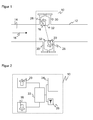
Eine Steuerung 22, beispielsweise ein Mikroprozessor oder eine andere Logik, wie ein FPGA, ein DSP, ein ASIC, steuert das Aussenden von Ultraschallsignalen durch die Ultraschallwandler 18, 20, beispielsweise als Pulsserie bei einer Ultraschallfrequenz von 80 kHz und größer und wertet die Laufzeiten der am gegenüberliegenden Ultraschallwandler 20, 18 empfangenen Signale aus. Daraus kann die Steuerung 22 mit dem einleitend im Zusammenhang mit der
Jeder Ultraschallwandler 18, 20 ist in einem Gehäuse 28 angeordnet, welches jeweils in einem senkrecht zur Rohrleitung orientierten Stutzen 30 durch senkrechte Flanschmontage befestigt wird. Im Bereich der Membranen der Ultraschallwandler 18, 20 zur Abstrahlung und zum Empfang von Ultraschall ist das Gehäuse 28 für Ultraschall durchlässig, weist eine Öffnung auf, oder die Membranen sind am Ort der Abstrahlung und des Empfangs in das Gehäuse 28 integriert. Die Ultraschallwandler 18, 20 sind gegenüber ihrem Gehäuse 28 um einen Winkel von beispielsweise 15° verkippt, damit der Messpfad in der einen Richtung mit der Strömung und in der anderen Richtung gegen die Strömung verläuft. Dieser Winkel kann, anders als in
Jedes Gehäuse 28 ragt aus dem zugehörigen Stutzen 30 ein Stück in den Innenraum der Rohrleitung 12 und damit in die Strömung des Fluids 14 hinein. Dabei ist diejenige Außenkontur 32 des Gehäuses 28, die in die Strömung hineinragt, strömungsoptimiert ausgebildet, um die Ausbildung von Abrisswirbeln in der Strömung an dem Gehäuse 28 zu unterdrücken. Die Außenkontur 32 ist daher bevorzugt glatt und konvex, bietet der Strömung also keine Kanten, Ecken sowie nach innen oder außen gerichtete Ausbuchtungen, in denen Turbulenzen und Wirbel entstehen oder verstärkt werden könnten. Die Form der Außenkontur 32 kann in Abhängigkeit der geplanten Anwendung, also besonders der Art des zu messenden Fluids und der zu erwartenden Strömungsgeschwindigkeiten, experimentell oder theoretisch bestimmt werden und sich dabei an aerodynamischen Formen orientieren, wie sie etwa aus der Luftfahrttechnik bekannt sind. Auch die in
In einer alternativen Ausführungsform kann anstelle des Gehäuses 28 der Ultraschallwandler 18, 20 selbst eine strömungsoptimierte Außenkontur aufweisen. Dieser Ultraschallwandler ist dann schräg zu montieren und seine Außenkontur wird sich für gewöhnlich nur für bestimmte Verkippungswinkel optimieren lassen. Die Ausführungsform mit einem Gehäuse 28 ist also insofern flexibler, als der Verkippungswinkel und in gewissem Rahmen auch eine Translation des Ultraschallwandlers 18, 20 relativ zu dem Gehäuse 28 unabhängig gewählt werden können.In an alternative embodiment, instead of
Die Gründe, warum eine strömungsoptimierte Kontur 32 die Messergebnisse drastisch verbessert, werden nun anhand der
An den scharfen Kanten der hier nicht mit der erfindungsgemäßen strömungsoptimierten Kontur 32 versehenen Ultraschallwandler 18, 20 bilden sich Abrisswirbel 38, die auch ein weitaus größeres Ausmaß annehmen können als dargestellt. Diese führen zu einer starken Signalverzerrung, nämlich einem störenden Lärmpegel an den Ultraschallwandlern 18, 20, der die Qualität der Geschwindigkeitsmessung erheblich beeinträchtigt und ab einer gewissen Geschwindigkeit des Fluids 14 eine Messung per Ultraschall für die Praxis untauglich macht. Die erfindungsgemäße strömungsoptimierte Außenkontur 32 ermöglicht also erst die Anwendung einer Ultraschallmessung bei Strömungsgeschwindigkeiten auch oberhalb einer Grenze von etwa 70 m/s wie beispielsweise in einer Flaregasleitung.On the sharp edges of the
Die Abrissturbulenzen oder Abrisswirbel 38 verstärken aber zusätzlich zu dem störenden Lärmpegel auch den Verwehungseffekt. In
In
Wie
Zur weiteren Strömungsoptimierung kann ein Gleichrichter in dem Innenraum der Rohrleitung 12 vorgesehen sein, welcher die Strömung des Fluids 12 für den Bereich der Messvorrichtung 10 linearisiert oder zumindest Turbulenzen verringert und der dafür in oder vor diesem Bereich angeordnet ist. Die Außenkontur 32, die Verformungen 44 und/oder der Gleichrichter können dabei auf ein Zusammenwirken zur möglichst weitgehenden Unterdrückung von Abrisswirbeln 38 optimiert werden.For further flow optimization, a rectifier can be provided in the interior of the
Es ist weiterhin denkbar, zusätzlich zu den Ultraschallwandlern 18, 20 weitere einzelne oder Paare von Ultraschallwandlern einzusetzen, um weitere Messpfade zu erhalten. Eine besondere Position für einen solchen zusätzlichen Ultraschallwandler ist stromabwärts in einem Bereich, in dem stärker verwehte Signalanteile empfangen werden, um somit durch den Empfang desselben Signals an unterschiedlichen Orten eine bessere Gesamtinformation zu erhalten. Alternativ oder zusätzlich können weitere Paare von Ultraschallwandlern eingesetzt werden, um nach Art eines klassischen Mehrpfadsystems einen örtlich anderen Anteil der Strömungsgeschwindigkeit zu messen. Jeder Messpfad gibt dabei Auskunft über die Strömungsgeschwindigkeit in seiner lokalen Umgebung. Ist die Strömung gestört, so muss dies nicht notwendig der mittleren Strömungsgeschwindigkeit entsprechen und es kann auch eine ungenaue Bestimmung des Volumendurchsatzes resultieren. Weitere Messpfade über den Querschnitt der Rohrleitung 12 verbreitern die Basis an Information über das Strömungsprofil und ermöglichen somit eine genauere Messung.It is furthermore conceivable, in addition to the
Die zu einer einzelnen Ausführungsform beschriebenen Merkmale lassen sich jeweils mit den anderen Ausführungsformen kombinieren. So ist beispielsweise möglich, Verformungen der Rohrleitung 12 zusätzlich zu einem Parallelversatz 40 der Ultraschallwandler 18, 20 vorzunehmen.The features described in a single embodiment can be combined with the other embodiments. For example, it is possible to make deformations of the
Claims (10)
dadurch gekennzeichnet,
dass der erste Ultraschallwandler (18) und/oder der zweite Ultraschallwandler (20) eine strömungsoptimierte Kontur (32) aufweisen, welche Abrisswirbel (38) an Kanten des Ultraschallwandlers (18, 20) unterdrückt.Measuring device (10) for determining a flow velocity and / or a flow of a fluid (14) flowing in a line (12) with at least one first ultrasonic transducer (18) and a second ultrasonic transducer (20) in the line (12) are arranged relative to one another during operation of the ultrasound emitted and received on a first measurement path from the first ultrasound transducer (18) to the second ultrasound transducer (20) in relation to a second measurement path in the reverse direction from the second ultrasound transducer (20) and from the first ultrasound transducer (18) received ultrasound has a flow rate dependent transit time difference,
characterized,
in that the first ultrasound transducer (18) and / or the second ultrasound transducer (20) have a flow-optimized contour (32) which suppresses tear-off vertebrae (38) at edges of the ultrasound transducer (18, 20).
wobei die Leitung (12) eine Rohrleitung mit zylindrischem oder rechteckigem Querschnitt ist, die für hohe Strömungsgeschwindigkeiten von zumindest
40 m/s oder sogar von zumindest 70 m/s ausgebildet ist, insbesondere eine Flaregasleitung ist.Measuring device (10) according to claim 1,
wherein the conduit (12) is a conduit of cylindrical or rectangular cross section suitable for high flow velocities of at least
40 m / s or even of at least 70 m / s is formed, in particular a Flaregasleitung is.
wobei zusätzliche Ultraschallwandler vorgesehen sind, welche dafür ausgebildet sind, die Strömungsgeschwindigkeit und/oder den Durchfluss auf mindestens einem weiteren Messpfad zu bestimmen.Measuring device (10) according to claim 1 or 2,
wherein additional ultrasonic transducers are provided, which are designed to determine the flow velocity and / or the flow on at least one further measurement path.
wobei die Ultraschallwandler (18, 20) an einer Wandung der Leitung (12) angeordnet sind, insbesondere in jeweils einem senkrecht zu der Leitung (12) angeordneten Stutzen (30) montiert oder angeschweißt sind, und zumindest mit einem Teilbereich in den von dem Fluid (14) durchströmten Innenraum hineinragen, und wobei insbesondere ein den jeweiligen Ultraschallwandler (18, 20) umgebender Leitungsteilbereich (44) der Wandung gemeinsam mit dem in den Innenraum ragenden Teilbereich (32) des Ultraschallwandlers (18, 20) die strömungsoptimierte Kontur bildet.Measuring device (10) according to one of the preceding claims,
wherein the ultrasonic transducers (18, 20) are arranged on a wall of the conduit (12), in particular in each case mounted or welded to a nozzle (30) arranged perpendicular to the conduit (12), and at least with a partial region into that of the fluid (14) through which the interior space flows, and in which, in particular, a line subregion (44) of the wall surrounding the respective ultrasonic transducer (18, 20) together with the subregion (32) of the ultrasonic transducer (18, 20) projecting into the interior space flow-optimized contour forms.
wobei die Ultraschallwandler (18, 20) in einem Gehäuse (28) untergebracht sind, welches die strömungsoptimierte Kontur (32) aufweist, und wobei das Gehäuse (28) an zumindest einer Seite eine glatte, konvexe Außenkontur hat.Measuring device (10) according to one of the preceding claims,
wherein the ultrasonic transducers (18, 20) are accommodated in a housing (28) having the flow-optimized contour (32), and wherein the housing (28) has a smooth, convex outer contour on at least one side.
wobei das Gehäuse (28) senkrecht in die Leitung (12) eingesetzt und jeder Ultraschallwandler (18, 20) mit seiner Abstrahlfläche um einen Winkel verkippt ist, so dass der erste und der zweite Messpfad gegenüber einer Querschnittsebene der Leitung (12) schräg verlaufen.Measuring device (10) according to one of the preceding claims,
wherein the housing (28) inserted vertically into the conduit (12) and each ultrasonic transducer (18, 20) is tilted with its radiating surface by an angle, so that the first and the second measuring path with respect to a cross-sectional plane of the conduit (12) are inclined.
wobei der erste Ultraschallwandler (18) und der zweite Ultraschallwandler (20) zueinander parallelverschoben angeordnet sind, so dass der erste Messpfad und der zweite Messpfad zueinander um einen Versatz (40) in Strömungsrichtung beabstandet verlaufen.Measuring device (10) according to one of the preceding claims,
wherein the first ultrasonic transducer (18) and the second ultrasonic transducer (20) are arranged in parallel displacement, so that the first measuring path and the second measuring path to each other by an offset (40) in the flow direction are spaced.
dadurch gekennzeichnet,
dass Abrisswirbel (38) an Kanten der Ultraschallwandler (18, 20) durch eine strömungsoptimierte Kontur (32) der Ultraschallwandler (18, 20) unterdrückt werden.Measuring method for determining a flow velocity and / or a flow of a fluid (14) flowing in a line (12), in particular a flare gas having a flow velocity of at least 70 m / s, wherein a flow-time-dependent transit time difference of ultrasound between two ultrasonic transducers ( 18, 20), namely ultrasound on a first measuring path and on a second measuring path extending in the opposite direction to the first measuring path,
characterized,
that demolition (38) at edges of the ultrasonic transducer (18, 20) by a flow-optimized contour (32) of the ultrasonic transducer (18, 20) are suppressed.
wobei die Messung auf Messpfaden erfolgt, die vollständig innerhalb eines Innenraums der Leitung (12) liegen, und zwar in der Nähe einer Wandung der Leitung beginnend und endend, und wobei die Messpfade gegenüber einer Querschnittsebene der Leitung (12) um einen Winkel verkippt sind.Measuring method according to claim 8,
wherein the measurement takes place on measurement paths which lie completely within an interior of the conduit (12), beginning and ending in the vicinity of a wall of the conduit, and wherein the measurement paths are opposite to one another Cross-sectional plane of the line (12) are tilted by an angle.
wobei die Messung unter einem Parallelversatz (40) in Strömungsrichtung des ersten gegenüber dem zweiten Messpfad erfolgt.Measuring method according to claim 8 or 9,
wherein the measurement takes place under a parallel offset (40) in the flow direction of the first relative to the second measurement path.
Priority Applications (3)
| Application Number | Priority Date | Filing Date | Title |
|---|---|---|---|
| EP08102712.0A EP2103912B1 (en) | 2008-03-18 | 2008-03-18 | Flow measurement with ultrasound |
| PL08102712T PL2103912T3 (en) | 2008-03-18 | 2008-03-18 | Flow measurement with ultrasound |
| EP20090100168 EP2103911B1 (en) | 2008-03-18 | 2009-03-06 | Flow measurement with ultrasound |
Applications Claiming Priority (1)
| Application Number | Priority Date | Filing Date | Title |
|---|---|---|---|
| EP08102712.0A EP2103912B1 (en) | 2008-03-18 | 2008-03-18 | Flow measurement with ultrasound |
Publications (2)
| Publication Number | Publication Date |
|---|---|
| EP2103912A1 true EP2103912A1 (en) | 2009-09-23 |
| EP2103912B1 EP2103912B1 (en) | 2016-09-07 |
Family
ID=39712670
Family Applications (2)
| Application Number | Title | Priority Date | Filing Date |
|---|---|---|---|
| EP08102712.0A Active EP2103912B1 (en) | 2008-03-18 | 2008-03-18 | Flow measurement with ultrasound |
| EP20090100168 Active EP2103911B1 (en) | 2008-03-18 | 2009-03-06 | Flow measurement with ultrasound |
Family Applications After (1)
| Application Number | Title | Priority Date | Filing Date |
|---|---|---|---|
| EP20090100168 Active EP2103911B1 (en) | 2008-03-18 | 2009-03-06 | Flow measurement with ultrasound |
Country Status (2)
| Country | Link |
|---|---|
| EP (2) | EP2103912B1 (en) |
| PL (1) | PL2103912T3 (en) |
Cited By (5)
| Publication number | Priority date | Publication date | Assignee | Title |
|---|---|---|---|---|
| DE102014106429A1 (en) | 2013-07-10 | 2015-01-15 | Sick Ag | Flow measuring device and method for measuring the flow rate of a fluid |
| EP3855134A1 (en) | 2020-01-21 | 2021-07-28 | SICK Engineering GmbH | Device for measuring the flow speed of a fluid |
| DE202020104105U1 (en) | 2020-07-16 | 2021-10-20 | Sick Engineering Gmbh | Flow meter for measuring the flow of a fluid |
| EP3940346A1 (en) | 2020-07-16 | 2022-01-19 | SICK Engineering GmbH | Flow meter and method for measuring the flow rate of a fluid |
| CN115905961A (en) * | 2023-03-09 | 2023-04-04 | 广东广宇科技发展有限公司 | Pipeline defect analysis method based on multi-source data |
Families Citing this family (5)
| Publication number | Priority date | Publication date | Assignee | Title |
|---|---|---|---|---|
| NL2005886C2 (en) * | 2010-12-21 | 2012-06-25 | Nest Internat N V | Device and method for determining a flow velocity of a fluid or a fluid component in a pipeline. |
| DE102014006743A1 (en) * | 2014-05-12 | 2015-11-12 | Wilo Se | Flow Sensor |
| DE102016103419A1 (en) * | 2016-02-26 | 2017-08-31 | Krohne Messtechnik Gmbh | Measuring rod for the detection of a flowing medium in a pipe and related measurement arrangement |
| PL3367072T3 (en) | 2017-02-24 | 2019-06-28 | Sick Engineering Gmbh | Flow measurement with ultrasound |
| DE102018126613B4 (en) * | 2018-10-25 | 2022-08-11 | Sensus Spectrum Llc | Measuring device for determining the flow of a fluid flowing through a pipe section |
Citations (7)
| Publication number | Priority date | Publication date | Assignee | Title |
|---|---|---|---|---|
| US5251490A (en) | 1992-02-07 | 1993-10-12 | Kronberg James W | Ultrasonic fluid flow measurement method and apparatus |
| EP0580099A2 (en) | 1992-07-23 | 1994-01-26 | G. Kromschröder AG | Ultrasonic gas meter |
| EP0622614A1 (en) | 1993-04-27 | 1994-11-02 | NUOVOPIGNONE INDUSTRIE MECCANICHE E FONDERIA S.p.A. | Ultrasound fluid flowmeter-controller |
| WO1996036852A1 (en) | 1995-05-17 | 1996-11-21 | Schlumberger Industries S.A. | Ultrasonic device for measuring a fluid flow rate |
| US6647804B1 (en) | 1999-02-10 | 2003-11-18 | Rd Instruments, Inc. | System and method for flow measurement in a pipe |
| DE102004060118A1 (en) | 2004-12-13 | 2006-06-14 | Endress + Hauser Flowtec Ag | Device for determining and / or monitoring volume and / or mass flow |
| DE102004060064A1 (en) | 2004-12-14 | 2006-06-29 | Robert Bosch Gmbh | Ultrasonic flow meter for measuring mass flow rate in automobiles has two ultrasonic transducers whereby in main flow direction turbulator is arranged on ultrasonic transducers which produce longitudinal vortices in adjacent area |
Family Cites Families (6)
| Publication number | Priority date | Publication date | Assignee | Title |
|---|---|---|---|---|
| DE2823497C3 (en) * | 1978-05-30 | 1982-01-21 | Drägerwerk AG, 2400 Lübeck | Method for measuring the flow rate of gases or liquids and device for this |
| US4754650A (en) | 1983-07-29 | 1988-07-05 | Panametrics, Inc. | Apparatus and methods for measuring fluid flow parameters |
| EP0690974A4 (en) * | 1993-03-09 | 1996-05-22 | Commw Scient Ind Res Org | Fluid meter construction |
| DE19859572A1 (en) * | 1998-12-22 | 2000-06-29 | Sick Ag | Ultrasonic measurement system for gas flow requiring access from one side of pipe line only |
| DE102004060062A1 (en) * | 2004-12-14 | 2006-06-29 | Robert Bosch Gmbh | Ultrasonic measuring device |
| DE102004060065B4 (en) * | 2004-12-14 | 2016-10-20 | Robert Bosch Gmbh | Ultrasonic flow meter with guide elements |
-
2008
- 2008-03-18 PL PL08102712T patent/PL2103912T3/en unknown
- 2008-03-18 EP EP08102712.0A patent/EP2103912B1/en active Active
-
2009
- 2009-03-06 EP EP20090100168 patent/EP2103911B1/en active Active
Patent Citations (7)
| Publication number | Priority date | Publication date | Assignee | Title |
|---|---|---|---|---|
| US5251490A (en) | 1992-02-07 | 1993-10-12 | Kronberg James W | Ultrasonic fluid flow measurement method and apparatus |
| EP0580099A2 (en) | 1992-07-23 | 1994-01-26 | G. Kromschröder AG | Ultrasonic gas meter |
| EP0622614A1 (en) | 1993-04-27 | 1994-11-02 | NUOVOPIGNONE INDUSTRIE MECCANICHE E FONDERIA S.p.A. | Ultrasound fluid flowmeter-controller |
| WO1996036852A1 (en) | 1995-05-17 | 1996-11-21 | Schlumberger Industries S.A. | Ultrasonic device for measuring a fluid flow rate |
| US6647804B1 (en) | 1999-02-10 | 2003-11-18 | Rd Instruments, Inc. | System and method for flow measurement in a pipe |
| DE102004060118A1 (en) | 2004-12-13 | 2006-06-14 | Endress + Hauser Flowtec Ag | Device for determining and / or monitoring volume and / or mass flow |
| DE102004060064A1 (en) | 2004-12-14 | 2006-06-29 | Robert Bosch Gmbh | Ultrasonic flow meter for measuring mass flow rate in automobiles has two ultrasonic transducers whereby in main flow direction turbulator is arranged on ultrasonic transducers which produce longitudinal vortices in adjacent area |
Cited By (7)
| Publication number | Priority date | Publication date | Assignee | Title |
|---|---|---|---|---|
| DE102014106429A1 (en) | 2013-07-10 | 2015-01-15 | Sick Ag | Flow measuring device and method for measuring the flow rate of a fluid |
| EP3855134A1 (en) | 2020-01-21 | 2021-07-28 | SICK Engineering GmbH | Device for measuring the flow speed of a fluid |
| US11619528B2 (en) | 2020-01-21 | 2023-04-04 | Sick Engineering Gmbh | Ultrasonic flow measuring device having a wall thickness being less in the area of the phased array ultrasonic transducer contact area |
| DE202020104105U1 (en) | 2020-07-16 | 2021-10-20 | Sick Engineering Gmbh | Flow meter for measuring the flow of a fluid |
| EP3940346A1 (en) | 2020-07-16 | 2022-01-19 | SICK Engineering GmbH | Flow meter and method for measuring the flow rate of a fluid |
| WO2022013653A1 (en) | 2020-07-16 | 2022-01-20 | Sick Engineering Gmbh | Flowmeter and method for measuring the flow of a fluid |
| CN115905961A (en) * | 2023-03-09 | 2023-04-04 | 广东广宇科技发展有限公司 | Pipeline defect analysis method based on multi-source data |
Also Published As
| Publication number | Publication date |
|---|---|
| EP2103911B1 (en) | 2014-09-03 |
| EP2103911A1 (en) | 2009-09-23 |
| PL2103912T3 (en) | 2017-02-28 |
| EP2103912B1 (en) | 2016-09-07 |
Similar Documents
| Publication | Publication Date | Title |
|---|---|---|
| EP2103912B1 (en) | Flow measurement with ultrasound | |
| EP1831649B1 (en) | Ultrasonic flowmeter having a pressure sensor | |
| EP2386835B1 (en) | Ultrasound measurement of the flow speed of a fluid in a tubular conduit | |
| EP2044391B1 (en) | Measuring system for a medium flowing in a process line | |
| DE102013114475B4 (en) | Ultrasonic measuring device and method for determining the flow velocity | |
| EP2710337B1 (en) | Ultrasonic flowmeter | |
| EP3004812A1 (en) | Ultrasonic flow meter | |
| EP3230696B1 (en) | Ultrasonic flow meter | |
| EP2818874B1 (en) | Ultrasound measuring device | |
| WO2014012707A1 (en) | Ultrasound flow rate meter | |
| EP3209976B1 (en) | Method for an ultrasound clamp-on flow measurement and circuit arrangement for control of an ultrasound clamp-on flow measurement | |
| EP2710336A1 (en) | Ultrasonic flowmeter | |
| WO2022013653A1 (en) | Flowmeter and method for measuring the flow of a fluid | |
| EP2656017A1 (en) | Coupling element of an ultrasonic transducer for an ultrasonic flow meter | |
| DE102008013224A1 (en) | Measuring system for determining and/or monitoring flow of measuring medium through measuring tube, has measuring tube, where signal path runs and partly lies in partial volume of tube on plane | |
| EP3343185B1 (en) | Ultrasound flow measuring device and method for measuring the flow | |
| WO2012084392A1 (en) | Ultrasonic flow meter | |
| EP3273205A1 (en) | Method and assembly for ultrasound clamp on flow measurement and body for realizing the measurement | |
| EP3748308A1 (en) | Ultrasound flow measuring device, blocking device and use in a blocking device | |
| EP3855134B1 (en) | Device for measuring the flow speed of a fluid | |
| DE102006019146B3 (en) | Device for determining the flow velocity of a fluid or gas in a pipe | |
| DE4341542C2 (en) | Flow measurement device | |
| EP3367072A1 (en) | Flow measurement with ultrasound | |
| EP0504304B1 (en) | Ultrasonic gas/liquid flow meter | |
| EP3715797A2 (en) | Ultrasonic flow meter, method for operating an ultrasonic flow meter, measuring assembly and method for operating a measuring assembly |
Legal Events
| Date | Code | Title | Description |
|---|---|---|---|
| PUAI | Public reference made under article 153(3) epc to a published international application that has entered the european phase |
Free format text: ORIGINAL CODE: 0009012 |
|
| 17P | Request for examination filed |
Effective date: 20081204 |
|
| AK | Designated contracting states |
Kind code of ref document: A1 Designated state(s): AT BE BG CH CY CZ DE DK EE ES FI FR GB GR HR HU IE IS IT LI LT LU LV MC MT NL NO PL PT RO SE SI SK TR |
|
| AX | Request for extension of the european patent |
Extension state: AL BA MK RS |
|
| AKX | Designation fees paid |
Designated state(s): AT BE BG CH CY CZ DE DK EE ES FI FR GB GR HR HU IE IS IT LI LT LU LV MC MT NL NO PL PT RO SE SI SK TR |
|
| 17Q | First examination report despatched |
Effective date: 20110503 |
|
| GRAP | Despatch of communication of intention to grant a patent |
Free format text: ORIGINAL CODE: EPIDOSNIGR1 |
|
| INTG | Intention to grant announced |
Effective date: 20160503 |
|
| GRAS | Grant fee paid |
Free format text: ORIGINAL CODE: EPIDOSNIGR3 |
|
| GRAA | (expected) grant |
Free format text: ORIGINAL CODE: 0009210 |
|
| AK | Designated contracting states |
Kind code of ref document: B1 Designated state(s): AT BE BG CH CY CZ DE DK EE ES FI FR GB GR HR HU IE IS IT LI LT LU LV MC MT NL NO PL PT RO SE SI SK TR |
|
| REG | Reference to a national code |
Ref country code: GB Ref legal event code: FG4D Free format text: NOT ENGLISH |
|
| REG | Reference to a national code |
Ref country code: CH Ref legal event code: EP |
|
| REG | Reference to a national code |
Ref country code: IE Ref legal event code: FG4D Free format text: LANGUAGE OF EP DOCUMENT: GERMAN |
|
| REG | Reference to a national code |
Ref country code: AT Ref legal event code: REF Ref document number: 827284 Country of ref document: AT Kind code of ref document: T Effective date: 20161015 |
|
| REG | Reference to a national code |
Ref country code: DE Ref legal event code: R096 Ref document number: 502008014604 Country of ref document: DE |
|
| REG | Reference to a national code |
Ref country code: NO Ref legal event code: T2 Effective date: 20160907 |
|
| REG | Reference to a national code |
Ref country code: LT Ref legal event code: MG4D |
|
| REG | Reference to a national code |
Ref country code: NL Ref legal event code: MP Effective date: 20160907 |
|
| PG25 | Lapsed in a contracting state [announced via postgrant information from national office to epo] |
Ref country code: LT Free format text: LAPSE BECAUSE OF FAILURE TO SUBMIT A TRANSLATION OF THE DESCRIPTION OR TO PAY THE FEE WITHIN THE PRESCRIBED TIME-LIMIT Effective date: 20160907 Ref country code: HR Free format text: LAPSE BECAUSE OF FAILURE TO SUBMIT A TRANSLATION OF THE DESCRIPTION OR TO PAY THE FEE WITHIN THE PRESCRIBED TIME-LIMIT Effective date: 20160907 Ref country code: FI Free format text: LAPSE BECAUSE OF FAILURE TO SUBMIT A TRANSLATION OF THE DESCRIPTION OR TO PAY THE FEE WITHIN THE PRESCRIBED TIME-LIMIT Effective date: 20160907 |
|
| PG25 | Lapsed in a contracting state [announced via postgrant information from national office to epo] |
Ref country code: LV Free format text: LAPSE BECAUSE OF FAILURE TO SUBMIT A TRANSLATION OF THE DESCRIPTION OR TO PAY THE FEE WITHIN THE PRESCRIBED TIME-LIMIT Effective date: 20160907 Ref country code: SE Free format text: LAPSE BECAUSE OF FAILURE TO SUBMIT A TRANSLATION OF THE DESCRIPTION OR TO PAY THE FEE WITHIN THE PRESCRIBED TIME-LIMIT Effective date: 20160907 Ref country code: GR Free format text: LAPSE BECAUSE OF FAILURE TO SUBMIT A TRANSLATION OF THE DESCRIPTION OR TO PAY THE FEE WITHIN THE PRESCRIBED TIME-LIMIT Effective date: 20161208 Ref country code: ES Free format text: LAPSE BECAUSE OF FAILURE TO SUBMIT A TRANSLATION OF THE DESCRIPTION OR TO PAY THE FEE WITHIN THE PRESCRIBED TIME-LIMIT Effective date: 20160907 Ref country code: NL Free format text: LAPSE BECAUSE OF FAILURE TO SUBMIT A TRANSLATION OF THE DESCRIPTION OR TO PAY THE FEE WITHIN THE PRESCRIBED TIME-LIMIT Effective date: 20160907 |
|
| PG25 | Lapsed in a contracting state [announced via postgrant information from national office to epo] |
Ref country code: RO Free format text: LAPSE BECAUSE OF FAILURE TO SUBMIT A TRANSLATION OF THE DESCRIPTION OR TO PAY THE FEE WITHIN THE PRESCRIBED TIME-LIMIT Effective date: 20160907 Ref country code: EE Free format text: LAPSE BECAUSE OF FAILURE TO SUBMIT A TRANSLATION OF THE DESCRIPTION OR TO PAY THE FEE WITHIN THE PRESCRIBED TIME-LIMIT Effective date: 20160907 |
|
| PG25 | Lapsed in a contracting state [announced via postgrant information from national office to epo] |
Ref country code: IS Free format text: LAPSE BECAUSE OF FAILURE TO SUBMIT A TRANSLATION OF THE DESCRIPTION OR TO PAY THE FEE WITHIN THE PRESCRIBED TIME-LIMIT Effective date: 20170107 Ref country code: BG Free format text: LAPSE BECAUSE OF FAILURE TO SUBMIT A TRANSLATION OF THE DESCRIPTION OR TO PAY THE FEE WITHIN THE PRESCRIBED TIME-LIMIT Effective date: 20161207 Ref country code: CZ Free format text: LAPSE BECAUSE OF FAILURE TO SUBMIT A TRANSLATION OF THE DESCRIPTION OR TO PAY THE FEE WITHIN THE PRESCRIBED TIME-LIMIT Effective date: 20160907 Ref country code: PT Free format text: LAPSE BECAUSE OF FAILURE TO SUBMIT A TRANSLATION OF THE DESCRIPTION OR TO PAY THE FEE WITHIN THE PRESCRIBED TIME-LIMIT Effective date: 20170109 Ref country code: SK Free format text: LAPSE BECAUSE OF FAILURE TO SUBMIT A TRANSLATION OF THE DESCRIPTION OR TO PAY THE FEE WITHIN THE PRESCRIBED TIME-LIMIT Effective date: 20160907 |
|
| REG | Reference to a national code |
Ref country code: DE Ref legal event code: R097 Ref document number: 502008014604 Country of ref document: DE |
|
| PG25 | Lapsed in a contracting state [announced via postgrant information from national office to epo] |
Ref country code: IT Free format text: LAPSE BECAUSE OF FAILURE TO SUBMIT A TRANSLATION OF THE DESCRIPTION OR TO PAY THE FEE WITHIN THE PRESCRIBED TIME-LIMIT Effective date: 20160907 |
|
| PLBE | No opposition filed within time limit |
Free format text: ORIGINAL CODE: 0009261 |
|
| STAA | Information on the status of an ep patent application or granted ep patent |
Free format text: STATUS: NO OPPOSITION FILED WITHIN TIME LIMIT |
|
| PG25 | Lapsed in a contracting state [announced via postgrant information from national office to epo] |
Ref country code: DK Free format text: LAPSE BECAUSE OF FAILURE TO SUBMIT A TRANSLATION OF THE DESCRIPTION OR TO PAY THE FEE WITHIN THE PRESCRIBED TIME-LIMIT Effective date: 20160907 |
|
| 26N | No opposition filed |
Effective date: 20170608 |
|
| PG25 | Lapsed in a contracting state [announced via postgrant information from national office to epo] |
Ref country code: SI Free format text: LAPSE BECAUSE OF FAILURE TO SUBMIT A TRANSLATION OF THE DESCRIPTION OR TO PAY THE FEE WITHIN THE PRESCRIBED TIME-LIMIT Effective date: 20160907 |
|
| REG | Reference to a national code |
Ref country code: CH Ref legal event code: PL |
|
| PG25 | Lapsed in a contracting state [announced via postgrant information from national office to epo] |
Ref country code: MC Free format text: LAPSE BECAUSE OF FAILURE TO SUBMIT A TRANSLATION OF THE DESCRIPTION OR TO PAY THE FEE WITHIN THE PRESCRIBED TIME-LIMIT Effective date: 20160907 |
|
| REG | Reference to a national code |
Ref country code: IE Ref legal event code: MM4A |
|
| REG | Reference to a national code |
Ref country code: FR Ref legal event code: ST Effective date: 20171130 |
|
| PG25 | Lapsed in a contracting state [announced via postgrant information from national office to epo] |
Ref country code: LU Free format text: LAPSE BECAUSE OF NON-PAYMENT OF DUE FEES Effective date: 20170318 Ref country code: FR Free format text: LAPSE BECAUSE OF NON-PAYMENT OF DUE FEES Effective date: 20170331 |
|
| PG25 | Lapsed in a contracting state [announced via postgrant information from national office to epo] |
Ref country code: LI Free format text: LAPSE BECAUSE OF NON-PAYMENT OF DUE FEES Effective date: 20170331 Ref country code: CH Free format text: LAPSE BECAUSE OF NON-PAYMENT OF DUE FEES Effective date: 20170331 Ref country code: IE Free format text: LAPSE BECAUSE OF NON-PAYMENT OF DUE FEES Effective date: 20170318 |
|
| REG | Reference to a national code |
Ref country code: BE Ref legal event code: MM Effective date: 20170331 |
|
| REG | Reference to a national code |
Ref country code: AT Ref legal event code: MM01 Ref document number: 827284 Country of ref document: AT Kind code of ref document: T Effective date: 20170318 |
|
| PG25 | Lapsed in a contracting state [announced via postgrant information from national office to epo] |
Ref country code: BE Free format text: LAPSE BECAUSE OF NON-PAYMENT OF DUE FEES Effective date: 20170331 |
|
| PG25 | Lapsed in a contracting state [announced via postgrant information from national office to epo] |
Ref country code: AT Free format text: LAPSE BECAUSE OF NON-PAYMENT OF DUE FEES Effective date: 20170318 |
|
| PG25 | Lapsed in a contracting state [announced via postgrant information from national office to epo] |
Ref country code: MT Free format text: LAPSE BECAUSE OF FAILURE TO SUBMIT A TRANSLATION OF THE DESCRIPTION OR TO PAY THE FEE WITHIN THE PRESCRIBED TIME-LIMIT Effective date: 20160907 |
|
| PG25 | Lapsed in a contracting state [announced via postgrant information from national office to epo] |
Ref country code: HU Free format text: LAPSE BECAUSE OF FAILURE TO SUBMIT A TRANSLATION OF THE DESCRIPTION OR TO PAY THE FEE WITHIN THE PRESCRIBED TIME-LIMIT; INVALID AB INITIO Effective date: 20080318 |
|
| PG25 | Lapsed in a contracting state [announced via postgrant information from national office to epo] |
Ref country code: CY Free format text: LAPSE BECAUSE OF NON-PAYMENT OF DUE FEES Effective date: 20160907 |
|
| PG25 | Lapsed in a contracting state [announced via postgrant information from national office to epo] |
Ref country code: TR Free format text: LAPSE BECAUSE OF FAILURE TO SUBMIT A TRANSLATION OF THE DESCRIPTION OR TO PAY THE FEE WITHIN THE PRESCRIBED TIME-LIMIT Effective date: 20160907 |
|
| PGFP | Annual fee paid to national office [announced via postgrant information from national office to epo] |
Ref country code: GB Payment date: 20220324 Year of fee payment: 15 |
|
| PGFP | Annual fee paid to national office [announced via postgrant information from national office to epo] |
Ref country code: NO Payment date: 20230321 Year of fee payment: 16 |
|
| PGFP | Annual fee paid to national office [announced via postgrant information from national office to epo] |
Ref country code: PL Payment date: 20230309 Year of fee payment: 16 Ref country code: DE Payment date: 20230320 Year of fee payment: 16 |
|
| GBPC | Gb: european patent ceased through non-payment of renewal fee |
Effective date: 20230318 |
|
| PG25 | Lapsed in a contracting state [announced via postgrant information from national office to epo] |
Ref country code: GB Free format text: LAPSE BECAUSE OF NON-PAYMENT OF DUE FEES Effective date: 20230318 |
|
| PG25 | Lapsed in a contracting state [announced via postgrant information from national office to epo] |
Ref country code: GB Free format text: LAPSE BECAUSE OF NON-PAYMENT OF DUE FEES Effective date: 20230318 |