EP2103792B1 - Gas turbine compressor with bleed air device - Google Patents
Gas turbine compressor with bleed air device Download PDFInfo
- Publication number
- EP2103792B1 EP2103792B1 EP09003325A EP09003325A EP2103792B1 EP 2103792 B1 EP2103792 B1 EP 2103792B1 EP 09003325 A EP09003325 A EP 09003325A EP 09003325 A EP09003325 A EP 09003325A EP 2103792 B1 EP2103792 B1 EP 2103792B1
- Authority
- EP
- European Patent Office
- Prior art keywords
- bleed
- circumferential
- angle
- compressor
- boa
- Prior art date
- Legal status (The legal status is an assumption and is not a legal conclusion. Google has not performed a legal analysis and makes no representation as to the accuracy of the status listed.)
- Active
Links
Images


Classifications
-
- F—MECHANICAL ENGINEERING; LIGHTING; HEATING; WEAPONS; BLASTING
- F02—COMBUSTION ENGINES; HOT-GAS OR COMBUSTION-PRODUCT ENGINE PLANTS
- F02C—GAS-TURBINE PLANTS; AIR INTAKES FOR JET-PROPULSION PLANTS; CONTROLLING FUEL SUPPLY IN AIR-BREATHING JET-PROPULSION PLANTS
- F02C6/00—Plural gas-turbine plants; Combinations of gas-turbine plants with other apparatus; Adaptations of gas- turbine plants for special use
- F02C6/04—Gas-turbine plants providing heated or pressurised working fluid for other apparatus, e.g. without mechanical power output
- F02C6/06—Gas-turbine plants providing heated or pressurised working fluid for other apparatus, e.g. without mechanical power output providing compressed gas
- F02C6/08—Gas-turbine plants providing heated or pressurised working fluid for other apparatus, e.g. without mechanical power output providing compressed gas the gas being bled from the gas-turbine compressor
-
- F—MECHANICAL ENGINEERING; LIGHTING; HEATING; WEAPONS; BLASTING
- F02—COMBUSTION ENGINES; HOT-GAS OR COMBUSTION-PRODUCT ENGINE PLANTS
- F02C—GAS-TURBINE PLANTS; AIR INTAKES FOR JET-PROPULSION PLANTS; CONTROLLING FUEL SUPPLY IN AIR-BREATHING JET-PROPULSION PLANTS
- F02C9/00—Controlling gas-turbine plants; Controlling fuel supply in air- breathing jet-propulsion plants
- F02C9/16—Control of working fluid flow
- F02C9/18—Control of working fluid flow by bleeding, bypassing or acting on variable working fluid interconnections between turbines or compressors or their stages
-
- F—MECHANICAL ENGINEERING; LIGHTING; HEATING; WEAPONS; BLASTING
- F04—POSITIVE - DISPLACEMENT MACHINES FOR LIQUIDS; PUMPS FOR LIQUIDS OR ELASTIC FLUIDS
- F04D—NON-POSITIVE-DISPLACEMENT PUMPS
- F04D29/00—Details, component parts, or accessories
- F04D29/40—Casings; Connections of working fluid
- F04D29/52—Casings; Connections of working fluid for axial pumps
- F04D29/54—Fluid-guiding means, e.g. diffusers
- F04D29/541—Specially adapted for elastic fluid pumps
- F04D29/542—Bladed diffusers
- F04D29/544—Blade shapes
-
- F—MECHANICAL ENGINEERING; LIGHTING; HEATING; WEAPONS; BLASTING
- F04—POSITIVE - DISPLACEMENT MACHINES FOR LIQUIDS; PUMPS FOR LIQUIDS OR ELASTIC FLUIDS
- F04D—NON-POSITIVE-DISPLACEMENT PUMPS
- F04D27/00—Control, e.g. regulation, of pumps, pumping installations or pumping systems specially adapted for elastic fluids
- F04D27/02—Surge control
- F04D27/0207—Surge control by bleeding, bypassing or recycling fluids
- F04D27/023—Details or means for fluid extraction
-
- F—MECHANICAL ENGINEERING; LIGHTING; HEATING; WEAPONS; BLASTING
- F05—INDEXING SCHEMES RELATING TO ENGINES OR PUMPS IN VARIOUS SUBCLASSES OF CLASSES F01-F04
- F05D—INDEXING SCHEME FOR ASPECTS RELATING TO NON-POSITIVE-DISPLACEMENT MACHINES OR ENGINES, GAS-TURBINES OR JET-PROPULSION PLANTS
- F05D2240/00—Components
- F05D2240/10—Stators
- F05D2240/12—Fluid guiding means, e.g. vanes
- F05D2240/122—Fluid guiding means, e.g. vanes related to the trailing edge of a stator vane
-
- Y—GENERAL TAGGING OF NEW TECHNOLOGICAL DEVELOPMENTS; GENERAL TAGGING OF CROSS-SECTIONAL TECHNOLOGIES SPANNING OVER SEVERAL SECTIONS OF THE IPC; TECHNICAL SUBJECTS COVERED BY FORMER USPC CROSS-REFERENCE ART COLLECTIONS [XRACs] AND DIGESTS
- Y02—TECHNOLOGIES OR APPLICATIONS FOR MITIGATION OR ADAPTATION AGAINST CLIMATE CHANGE
- Y02T—CLIMATE CHANGE MITIGATION TECHNOLOGIES RELATED TO TRANSPORTATION
- Y02T50/00—Aeronautics or air transport
- Y02T50/60—Efficient propulsion technologies, e.g. for aircraft
Definitions
- the invention relates to a gas turbine compressor according to the features of the preamble of claim 1.
- the invention relates to a gas turbine compressor from which bleed air is taken in a housing region.
- Turbomachinery converts compressors (turbo-compressors) to supply subsystems or external users, such as the aircraft cabin, for purposes of stabilizing the compressor during transient maneuvers, for turbine cooling, or for recirculating flow within the compressor at different positions taken from the compressor housing ( Fig. 1 ).
- This removal can be done either between two rows of blades or within a row of blades ( Fig. 2 ) or a combination of both.
- the removal geometry can in principle have any conceivable shape.
- the air extraction geometry is either a circumferential slot 7 or a discrete hole 8 or a combination of both on the compressor housing.
- the geometry of the air extraction is very simple and therefore not optimally matched to the flow conditions that prevail at the sampling point near the compressor housing. As a result, the flow can not optimally flow into the bleed air sampling geometry. This leads, for example, to flow separation when the flow enters the extraction geometry and to high pressure loss within the extraction geometry.
- Another problem is an undesirable interaction between the flow in the compressor and the flow in the extraction geometry. This leads, for example, to Flow backflow from the extraction geometry into the main flow. This leads to loss of compressor efficiency, loss of compressor stability, and possibly mechanical stimulation of the compressor blade through to blade failure.
- the EP-A-1 801 403 describes a gas turbine compressor in which recesses of a bleed air sampling device are formed in the housing.
- the bleed air flows over rounded edges with a strong radius in a directly adjoining the recess, arranged radially to the machine axis channel.
- the EP-A-0 638 725 shows a similar arrangement in which the bleed air is removed at a housing stage with a directed against the flow direction channel, wherein the housing radius widens downstream of the channel.
- the EP-A-1 329 615 shows a configuration with bleed air-Aus SpotifyausEnglishungen which are formed on the rotor.
- the invention has for its object to provide a gas turbine compressor of the type mentioned, which has a high efficiency with a simple structure and ease of manufacture.
- a bleed air extraction geometry adapted to the flow conditions prevailing in the compressor at the removal point solves the problems described above.
- the solution according to the invention thus relates to an adapted bleed air extraction geometry for the air extraction between two blade rows (rotor 3 / stator 4 or stator 4 / rotor 3 but also stator 4 / stator 4 or rotor 3 / rotor 3) and in front of or behind a row of blades ( Rotor 3 or stator 4).
- This may be according to the invention to axial or radial compressor in a turbo- or turbomachine.
- the bleed air extraction geometry according to the invention is characterized by minimal pressure loss and maximum efficiency.
- the present invention describes an optimized removal geometry that can be described with the aid of a few geometric and machine-specific parameters.
- the idea on which the invention is based is to design the removal geometry so that the flow can flow without disruption into the removal geometry, which leads to a minimization of the local total pressure loss and is deflected within the removal geometry such that the swirl of the flow Zero is reduced and thereby a maximum of static pressure recovery is achieved.
- the extraction geometry is inclined on the one hand in a defined angle in the circumferential direction to the compressor housing and on the other hand receives a profiling in the axial direction adapted to the direction of the flow flowing into the extraction geometry.
- This flow direction becomes in the case that before, i. upstream of the sampling point, a stator blade is located, determined from the vane Abströmwinkel, in the event that upstream is a rotor blade, determined from the blade Abströmwinkel and the speed.
- the relevant quantity is the flow direction parallel to the machine axis, i. 0 degrees.
- the Fig. 1 shows a schematic representation in axial section view of a housing 1 and a rotatably mounted hub 2, on which rotor blades 3 are arranged.
- the housing carries in a known manner stator blades 4.
- the machine axis is provided with the reference numeral 5.
- the shows Fig. 1 in a schematic representation bleed air sampling devices 6 or bleed air extraction geometries.
- Fig. 2 again shown in schematic representation, namely as a circumferential slot 7 or as a discrete hole or recesses. 8
- the Fig. 3 shows first illustrations for explaining the invention.
- the upper part of the Fig. 3 shows the definition of the rotor metal angle MW ROTOR , which is defined to a parallel to the machine axis 5 arranged straight lines.
- the lower part of the Fig. 3 shows (also in magnification) a stator blade with pressure side DS and suction side SS and the definition of the angle and angle ranges.
- the Fig. 4 shows in axial view schematically a Axialraums leading edge 14 and an axial direction trailing edge 15 of a bleed air sampling / bleed air extraction geometry 6. Furthermore, further design information, in particular to r G and r N shown.
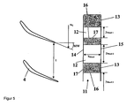
- the Fig. 5 shows a housing view with a viewing direction in the radial direction to the outside, from which can be seen in a strip-shaped peripheral portion 11 recesses 12. These have the aforementioned circumferential direction leading edges 16 and circumferential direction trailing edges 17 and axial direction leading edges 14 and axial direction trailing edges 15. Furthermore, the design results in the X direction and Y direction, from which the surfaces of the recesses 12 are calculated.
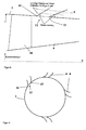
- the Fig. 6 shows an end view in which the arcuate contours of the hub 2 and a housing surface 18 of the housing 1 are reproduced greatly enlarged. This results in particular in the definition of the entrance angle ⁇ E and the exit angle ⁇ A.
- the Fig. 7 shows an analog representation of Fig. 5 with further angle definitions.
- the Fig. 8 shows an axial side view, from which it is particularly apparent that in the axial direction, the angle at the axial direction leading edge 14 and the axial direction trailing edge 15 may be arbitrary.
- the Fig. 9 shows possible distributions of the arrangements of the bleed air extraction devices 6, these may be arranged uniformly or non-uniformly on the circumference.
- the solution according to the invention advantageously leads to minimize the pressure losses in bleed air sampling geometries and to prevent the negative interaction with the main compressor flow.
- bleed air extraction is more efficient than non-optimized geometry.
- the turbine cooling, the compressor stabilization and the cabin printing can be realized more efficiently.
- This leads to improved compressor flow, improved bleed air flow and thus to improved compressor efficiency, stability and Finally, lower fuel consumption of the engine.
- the improved geometry is easy to manufacture and does not require any additional manufacturing technology costs, it is cost-neutral. In addition, it does not add weight to the compactor module as it replaces existing geometries.
Description
Die Erfindung bezieht sich auf einen Gasturbinenverdichter gemäß den Merkmalen des Oberbegriffs des Anspruches 1.The invention relates to a gas turbine compressor according to the features of the preamble of
Im Einzelnen bezieht sich die Erfindung auf einen Gasturbinensverdichter, aus welchem in einem Gehäusebereich Zapfluft (bleed air) entnommen wird.In detail, the invention relates to a gas turbine compressor from which bleed air is taken in a housing region.
In Turbomaschinen wird aus Verdichtern (Turboverdichter) zum Zwecke der Versorgung von Subsystemen oder externen Abnehmern, wie zum Beispiel der Flugzeugkabine, zum Zwecke der Stabilisierung des Verdichters bei transienten Manövern, zum Zwecke der Turbinenkühlung oder zum Zwecke der Strömungsrezirkulation innerhalb des Verdichters Zapfluft an verschiedenen Positionen am Verdichtergehäuse entnommen (
Die Luftentnahmegeometrie ist entweder ein Umfangsschlitz 7 oder ein diskretes Loch 8 oder eine Kombination aus beidem am Verdichtergehäuse. Die Geometrie der Luftentnahme ist sehr einfach gestaltet und daher nicht optimal auf die Strömungsverhältnisse abgestimmt, die an der Entnahmestelle nahe dem Verdichtergehäuse vorherrschen. Dies führt dazu, dass die Strömung nicht optimal in die Zapfluftentnahmegeometrie einfließen kann. Das führt zum Beispiel zu Strömungsablösung beim Eintritt der Strömung in die Entnahmegeometrie und zu hohem Druckverlust innerhalb der Entnahmegeometrie. Ein weiteres Problem ist eine unerwünschte Wechselwirkung zwischen der Strömung im Verdichter und der Strömung in der Entnahmegeometrie. Das führt zum Beispiel zu Strömungsrückfluss aus der Entnahmegeometrie in die Hauptströmung. Das führt zu Verlust von Verdichterwirkungsgrad, zu Verlust von Verdichterstabilität und gegebenenfalls zu einer mechanischen Anregung der Verdichterbeschaufelung bis hin zum Schaufelversagen.The air extraction geometry is either a
Die
Die
Die
Der Erfindung liegt die Aufgabe zugrunde, einen Gasturbinenverdichter der eingangs genannten Art zu schaffen, welcher bei einfachem Aufbau und einfacher Herstellbarkeit einen hohen Wirkungsgrad aufweist.The invention has for its object to provide a gas turbine compressor of the type mentioned, which has a high efficiency with a simple structure and ease of manufacture.
Erfindungsgemäß wird die Aufgabe durch die Merkmalskombination des Anspruchs 1 gelöst, die Unteransprüche zeigen weitere vorteilhafte Ausgestaltungen der Erfindung.According to the invention the object is achieved by the combination of features of
Erfindungsgemäß löst eine, auf die im Verdichter an der Entnahmestelle vorherrschenden Strömungsbedingungen angepasste, Zapfluftentnahmegeometrie die oben beschriebenen Probleme. Im speziellen betrifft die erfindungsgemäße Lösung somit eine angepasste Zapfluftentnahmegeometrie für die Luftentnahme zwischen zwei Schaufelreihen (Rotor 3 / Stator 4 bzw. Stator 4 / Rotor 3 aber auch Stator 4 / Stator 4 oder Rotor 3 / Rotor 3) und vor oder hinter einer Schaufelreihe (Rotor 3 oder Stator 4). Dabei kann es sich erfindungsgemäß um Axial- oder Radialverdichter in einer Turbo- bzw. Strömungsmaschine handeln.According to the invention, a bleed air extraction geometry adapted to the flow conditions prevailing in the compressor at the removal point solves the problems described above. In particular, the solution according to the invention thus relates to an adapted bleed air extraction geometry for the air extraction between two blade rows (
Die erfindungsgemäße Zapfluftentnahmegeometrie zeichnet sich durch minimalen Druckverlust und maximale Effizienz aus.The bleed air extraction geometry according to the invention is characterized by minimal pressure loss and maximum efficiency.
Die vorliegende Erfindung beschreibt eine optimierte Entnahmegeometrie, die sich mit Hilfe von wenigen geometrischen und maschinenspezifischen Parametern beschreiben lässt.The present invention describes an optimized removal geometry that can be described with the aid of a few geometric and machine-specific parameters.
Die Idee, die der Erfindung zugrunde liegt, ist, die Entnahmegeometrie so zu gestalten, dass die Strömung ohne Störung in die Entnahmegeometrie einfließen kann, was zu einer Minimierung des lokalen Totaldruckverlustes führt und innerhalb der Entnahmegeometrie so umgelenkt wird, dass der Drall der Strömung auf Null reduziert wird und dadurch ein Maximum an statischer Druckrückgewinnung erzielt wird.The idea on which the invention is based is to design the removal geometry so that the flow can flow without disruption into the removal geometry, which leads to a minimization of the local total pressure loss and is deflected within the removal geometry such that the swirl of the flow Zero is reduced and thereby a maximum of static pressure recovery is achieved.
Dies kann dadurch erreicht werden, dass die Entnahmegeometrie zum einen in einem definierten Winkel in Umfangsrichtung zum Verdichtergehäuse geneigt ist und zum anderen eine auf die Richtung der in die Entnahmegeometrie einfließende Strömung angepasste Profilierung in Axialrichtung erhält. Diese Strömungsrichtung wird für den Fall, dass sich vor, d.h. stromauf der Entnahmestelle eine Statorschaufel befindet, aus deren Schaufel-Abströmwinkel bestimmt, für den Fall dass sich stromauf eine Rotorschaufel befindet, aus deren Schaufel-Abströmwinkel und der Drehzahl bestimmt. Für den Fall, dass sich keine Schaufel stromauf der Entnahmegeometrie befindet, ist die maßgebliche Größe die Strömungsrichtung parallel zur Maschinenachse, d.h. 0 Grad.This can be achieved by the fact that the extraction geometry is inclined on the one hand in a defined angle in the circumferential direction to the compressor housing and on the other hand receives a profiling in the axial direction adapted to the direction of the flow flowing into the extraction geometry. This flow direction becomes in the case that before, i. upstream of the sampling point, a stator blade is located, determined from the vane Abströmwinkel, in the event that upstream is a rotor blade, determined from the blade Abströmwinkel and the speed. In the event that there is no blade upstream of the sampling geometry, the relevant quantity is the flow direction parallel to the machine axis, i. 0 degrees.
Im Folgenden wird die Erfindung im Detail beschrieben:
- 1.) Die Zapfluftentnahmestelle befindet sich am Verdichtergehäuse zwischen zwei Schaufelreihen oder vor oder hinter einer Schaufelreihe. Die Zapfluftentnahmestelle kann dabei eine beliebige Erstreckung in Axial- sowie in Umfangsrichtung haben.
- 2.) Wenn eine Schaufelreihe stromauf der Zapfluftentnahmestelle existiert (Rotor oder Stator) zeichnet sie sich dadurch aus, dass sie einen Profilaustrittswinkel (Metallwinkel) nahe der Verdichtergehäusewand aufweist (
Fig. 3 ). Der Profilaustrittswinkel ist eine messbare Größe, die sich aus dem Mittelwert des saugseitigen (SS) und druckseitigen (DS) Profilwinkels ergibt (Fig. 3 ). Nahe der Gehäusewand bedeutet in einem Abstand kleiner 5% der Schaufelhöhe h (Fig. 4 ). - 3.) Dieser Metallaustrittswinkel MW ist ein Parameter für die Definition der Zapfluftentnahmegeometrie.
- 4.) Ein weiterer Parameter ist die Umfangsgeschwindigkeit am Verdichtergehäuse uG, die sich aus der Drehzahl des Verdichters NCOMPRESSOR [1/s] und dem Gehäuseradius rG an der Vorderkante der Zapfluftentnahmegeometrie berechnet zu

und das Nabenverhältnis
an der Vorderkante der Zapfluftentnahmegeometrie (Fig. 3 und4 ). Dabei ist nCOMPRESSOR eine beliebige reelle Zahl. - 5.) Ein weiterer Parameter ist die zu entnehmende Luftmenge ξ definiert als Entnahmeluftmenge mBLEED bezogen auf die Luftmenge die in den Verdichter eintritt mCOMPRESSOR:

- 6.) Außerdem sind die Schaufelzahlen der Schaufelreihe vor bzw. hinter der Entnahmegeometrie zu berücksichtigen.
- 7.) Mit diesen bekannten Parametern lässt sich die Entnahmegeometrie definieren.
- 8.) Die Entnahmegeometrie setzt sich aus mehreren diskreten Entnahmekanälen zusammen die sich durch eine definierte Erstreckung und Form in Umfangsrichtung und in axiale Richtung auszeichnen und eine Fläche wie dargestellt in
Fig. 5 aufweisen. - 9.) Die Anzahl der Entnahmekanäle NBLEED kann beliebig sein, idealerweise jedoch ein ganzzahliges Vielfaches oder ein ganzzahliger Teiler der Schaufelzahl der Schaufelreihe vor bzw. hinter der Entnahmestelle.
- 10.) Die Umfangserstreckung yBLEED eines Entnahmekanals (
Fig. 5 ) kann ebenfalls beliebig sein, sollte jedoch ein ganzzahliger Teiler oder Vielfaches der Gehäuseteilung t der Schaufelreihe stromab oder stromauf sein. - 11.) Die axiale Erstreckung xBLEED (
Fig. 5 ) kann ebenfalls beliebig sein, kann jedoch maximal den vorhandenen axialen Raum zwischen zwei Schaufelreihen einnehmen. - 12.) Die Erstreckung in Umfangs - und Axialrichtung muss jedoch in Kombination mit der Anzahl der Entnahmekanäle die Bedingung erfüllen, dass die Gesamtfläche ABLEED so groß ist, dass die gewünschte Zapfluftmenge mBLEED bezogen auf die Verdichtereintrittsluftmenge mCOMPRESSOR abgenommen werden kann. Die Größen ABLEED und ξ = mBLEED/ mCOMPRESSOR sind Eingangsparameter für die Entnahmegeometriedimensionierung. Das heißt:

muss erfüllt sein. - 13.) Die Definition der Form der Entnahmegeometrie in Umfangsrichtung in der y-r-Ebene wird wie folgt definiert: Die Form in Umfangsrichtung hängt vom Eintrittswinkel der Strömung in die Entnahmegeometrie βE und vom Austrittswinkel aus der Entnahmegeometrie βA ab (
Fig. 6 ). Der Austrittswinkel relativ zur Maschinenachse ist radial bzw. 90 Grad zum Verdichtergehäuse (drallfrei). Der Eintrittswinkel lässt sich mit Hilfe folgender Größen bestimmen:
- a) Wenn eine Statorschaufel stromauf der Entnahmegeometrie existiert, entspricht BOA dem Metallaustrittswinkel der Statorschaufel MWSTATOR nahe dem Gehäuse ± 10 Grad (
Fig. 3 ). Nahe dem Gehäuse bedeutet in einem Bereich zwischen 95 und 100% der Schaufelhöhe. Somit kann BOA bei z.B. einem Wert des Metallaustrittswinkels nahe dem Gehäuse von 20-25 Grad Werte zwischen 10 und 35 Grad annehmen. - b) Wenn eine Rotorschaufel stromauf der Entnahmegeometrie existiert, ergibt sich BOA aus dem Metallaustrittswinkel der Rotorschaufel MWROTOR nahe dem Gehäuse ± 10 Grad gemäß folgender Gleichung

Nahe dem Gehäuse bedeutet in einem Bereich zwischen 95 und 100% der Schaufelhöhe. Somit kann BOA bei z.B. einem Wert des Metallaustrittswinkels nahe dem Gehäuse von 20-25 Grad Werte zwischen 46.9 und 68.6 Grad annehmen. - c) Wenn keine Schaufelreihe stromab der Entnahmestelle existiert, ist BOA = 0 Grad.
Der Eintrittswinkel der Strömung in die Entnahmegeometrie βE berechnet sich dann mit den bekannten Größen zu:
Damit sind der Eintrittswinkel βE und der Austrittswinkel βA definiert (Fig. 6 ). Die Verbindung zwischen diesen beiden Winkeln wird durch eine stetige wendepunktfreie Linie realisiert die an ihrem Anfangspunkt die Tangentensteigung βE und an ihrem Endpunkt die Tangentensteigung βA aufweist. - a) Wenn eine Statorschaufel stromauf der Entnahmegeometrie existiert, entspricht BOA dem Metallaustrittswinkel der Statorschaufel MWSTATOR nahe dem Gehäuse ± 10 Grad (
- 14.) Die axiale Form in der x-y- Ebene (
Fig. 7 ), wird definiert durch den bereits definierten Winkel BOA an der Vorderkante der Entnahmegeometrie ± 10 Grad und einem Winkel an der Hinterkante WHK der Entnahmegeometrie, der beliebige Werte zwischen +10 Grad und -10 Grad annehmen kann, idealerweise jedoch 0 Grad beträgt. Die Verbindung zwischen diesen beiden Winkeln wird durch eine stetige wendepunktfreie Linie realisiert, die an ihrem Anfangspunkt die Tangentensteigung BOA und an ihrem Endpunkt die Tangentensteigung WHK aufweist. Diese Definition gilt für jeden achsparallelen Schnitt durch die Entnahmegeometrie in der x-y-Ebene auf beliebiger radialer Position in der Entnahmegeometrie (Fig. 8 ). - 15.) Die Neigung der Zapfluftentnahmegeometrie gegenüber der Maschinenachse x ist beliebig (
Fig. 8 ). - 16.) Die Entnahmekanäle können beliebig über den Umfang (y) verteilt zueinander angeordnet werden, wie in
Fig. 9 gezeigt.
- 1.) The bleed air sampling point is located on the compressor housing between two rows of blades or in front of or behind a row of blades. The bleed air sampling point can have any extension in the axial and in the circumferential direction.
- 2.) If a row of blades exists upstream of the bleed air intake point (rotor or stator), it distinguishes itself by having a profile exit angle (Metal angle) near the compressor housing wall (
Fig. 3 ). The profile exit angle is a measurable quantity, which results from the mean value of the suction side (SS) and pressure side (DS) profile angle (Fig. 3 ). Close to the housing wall means at a distance of less than 5% of the blade height h (Fig. 4 ). - 3.) This metal outlet angle MW is a parameter for the definition of the bleed air sampling geometry.
- 4.) Another parameter is the peripheral speed at the compressor casing u G , which is calculated from the speed of the compressor N COMPRESSOR [1 / s] and the casing radius r G at the front edge of the bleed air sampling geometry
and the hub ratio
at the leading edge of the bleed air sampling geometry (Fig. 3 and4 ). Where n COMPRESSOR is any real number. - 5.) Another parameter is the amount of air to be extracted ξ defined as the withdrawal air volume m BLEED in relation to the amount of air entering the compressor m COMPRESSOR :
- 6.) In addition, the number of blades of the blade row in front of or behind the removal geometry must be taken into account.
- 7.) With these known parameters, the removal geometry can be defined.
- 8.) The extraction geometry is composed of several discrete extraction channels which are characterized by a defined extent and shape in the circumferential direction and in the axial direction and a surface as shown in FIG
Fig. 5 exhibit. - 9.) The number of sampling channels N BLEED can be arbitrary, but ideally an integer multiple or an integral divisor of the number of blades of the blade row in front of or behind the sampling point.
- 10.) The circumferential extent y BLEED of a withdrawal channel (
Fig. 5 ) may also be arbitrary, but should be an integer divisor or multiple of the housing pitch t of the blade row downstream or upstream. - 11.) The axial extent x BLEED (
Fig. 5 ) can also be arbitrary, but can occupy a maximum of the existing axial space between two rows of blades. - 12.) The extension in scope - but and the axial direction must satisfy the condition that the total area A BLEED is so large that the desired amount of bleed air m BLEED based in combination with the number of sampling channels can be removed to the compressor inlet air quantity m COMPRESSOR. The quantities A BLEED and ξ = m BLEED / m COMPRESSOR are input parameters for the extraction geometry dimensioning . This means:
must be fulfilled. - 13.) The definition of the shape of the extraction geometry in the circumferential direction in the yr plane is defined as follows: The shape in the circumferential direction depends on the entry angle of the flow into the removal geometry β E and on the exit angle from the removal geometry β A (
Fig. 6 ). The exit angle relative to the machine axis is radial or 90 degrees to the compressor housing (twist-free). The entrance angle can be determined using the following variables:- a) If a stator blade exists upstream of the sampling geometry , BOA corresponds to the metal exit angle of the stator stator MW STATOR near the housing ± 10 degrees (
Fig. 3 ). Near the housing means in a range between 95 and 100% of the blade height. Thus, for example, BOA may assume values between 10 and 35 degrees for the metal exit angle near the housing of 20-25 degrees. - b) If a rotor blade exists upstream of the sampling geometry, BOA results from the metal exit angle of the rotor blade MW ROTOR near the housing ± 10 degrees according to the following equation
Near the housing means in a range between 95 and 100% of the blade height. Thus, for example, BOA may have a value of Metal exit angles near the housing of 20-25 degrees assume values between 46.9 and 68.6 degrees. - c) If there is no row of blades downstream of the sampling point, BOA = 0 degrees.
The inlet angle of the flow into the extraction geometry β E is then calculated with the known quantities:
Thus, the entrance angle β E and the exit angle β A are defined (Fig. 6 ). The connection between these two angles is realized by a continuous turning-dot-free line which has the tangent slope β E at its starting point and the tangent slope β A at its end point. - a) If a stator blade exists upstream of the sampling geometry , BOA corresponds to the metal exit angle of the stator stator MW STATOR near the housing ± 10 degrees (
- 14.) The axial shape in the xy plane (
Fig. 7 ), is defined by the already defined angle BOA at the leading edge of the extraction geometry ± 10 degrees and an angle at the trailing edge WHK of the extraction geometry, which can take any values between +10 degrees and -10 degrees, but ideally is 0 degrees. The connection between these two angles is realized by a continuous turning-dot-free line, which has at its starting point the tangent slope BOA and at its end point the tangent slope WHK. This definition applies to any axis-parallel section through the removal geometry in the xy plane at any radial position in the removal geometry (Fig. 8 ). - 15.) The inclination of the bleed air extraction geometry with respect to the machine axis x is arbitrary (
Fig. 8 ). - 16.) The removal channels can be arranged arbitrarily distributed over the circumference (y), as in
Fig. 9 shown.
Im Folgenden wird die Erfindung anhand von Ausführungsbeispielen in Verbindung mit der Zeichnung beschrieben. Dabei zeigt:
- Fig. 1
- eine schematische Axialschnittansicht eines Verdichters mit Zapfluftentnahme gemäß dem Stand der Technik,
- Fig. 2
- eine schematische Darstellung des Standes der Technik mit Zapfluftentnahmepositionen in Blickrichtung radial nach außen auf die Gehäuseinnenwandung,
- Fig. 3
- schematische Darstellungen, in analoger Ansicht der
Fig. 2 zur Definition verschiedener Winkel, - Fig. 4
- eine Axialschnittansicht, ebenfalls schematisch, analog
Fig. 1 , - Fig. 5
- eine Darstellung der erfindungsgemäßen Ausgestaltung in Blickrichtung analog
Fig. 2 , - Fig. 6
- eine stirnseitige Ansicht (auf eine Radialebene, eines erfindungsgemäßen Ausgestaltungsbeispiels),
- Fig. 7
- eine Darstellung, analog
Fig. 5 , weiterer Ausgestaltungsbeispiele, - Fig. 8
- eine Axialschnittansicht in erfindungsgemäßer Ausgestaltung, und
- Fig. 9
- eine Radialebenen-Schnittansicht in vereinfachter Darstellung.
- Fig. 1
- FIG. 2 is a schematic axial sectional view of a prior art bleed air bleed compressor; FIG.
- Fig. 2
- a schematic representation of the prior art with bleed air extraction positions in the direction radially outward on the Gehäuseinnenwandung,
- Fig. 3
- schematic representations, in analogous view of
Fig. 2 to define different angles, - Fig. 4
- an axial sectional view, also schematically, analog
Fig. 1 . - Fig. 5
- a representation of the embodiment according to the invention in the viewing direction analog
Fig. 2 . - Fig. 6
- an end view (on a radial plane, a design example according to the invention),
- Fig. 7
- a representation, analog
Fig. 5 , further exemplary embodiments, - Fig. 8
- an axial sectional view in inventive design, and
- Fig. 9
- a radial plane sectional view in a simplified representation.
Die
Die
Die
Die
Die
Die
Die
Die
Die erfindungsgemäße Lösung führt in vorteilhafter Weise dazu, die Druckverluste in Zapfluftentnahmegeometrien zu minimieren und die negative Wechselwirkung mit der Verdichterhauptströmung zu verhindern. Das führt dazu, dass die Zapfluftentnahme effizienter ist als bei nicht optimierter Geometrie. Damit kann z.B. die Turbinenkühlung, die Verdichterstabilisierung sowie die Kabinenbedruckung effizienter realisiert werden. Dies führt zu verbesserter Verdichterströmung, verbesserter Zapfluftströmung und damit zu verbessertem Verdichterwirkungsgrad, Stabilität und schließlich geringerem Treibstoffverbrauch des Triebwerks. Da die verbesserte Geometrie einfach zu fertigen ist und keinen zusätzlichen Aufwand an Fertigungstechnologie bedeutet, ist sie kostenneutral. Außerdem bedeutet sie kein zusätzliches Gewicht für das Verdichtermodul, da sie vorhandene Geometrien ersetzt.The solution according to the invention advantageously leads to minimize the pressure losses in bleed air sampling geometries and to prevent the negative interaction with the main compressor flow. As a result, bleed air extraction is more efficient than non-optimized geometry. Thus, for example, the turbine cooling, the compressor stabilization and the cabin printing can be realized more efficiently. This leads to improved compressor flow, improved bleed air flow and thus to improved compressor efficiency, stability and Finally, lower fuel consumption of the engine. Because the improved geometry is easy to manufacture and does not require any additional manufacturing technology costs, it is cost-neutral. In addition, it does not add weight to the compactor module as it replaces existing geometries.
- 11
- Gehäuse / VerdichtergehäuseHousing / compressor housing
- 22
- Nabe / RotornabeHub / rotor hub
- 33
- Rotor / Rotorschaufel / Rotorschaufelreihe (R)Rotor / Rotor Blade / Rotor Blade Row (R)
- 44
- Stator / Statorschaufel / Statorschaufelreihe (S)Stator / stator blade / stator blade row (S)
- 55
- Maschinenachsemachine axis
- 66
- Zapfluftentnahmevorrichtung / ZapfluftentnahmegeometrieBleed air sampling device / bleed air sampling geometry
- 77
- Umfangsschlitzcircumferential slot
- 88th
- diskretes Loch / Ausnehmungdiscrete hole / recess
- 99
- Verdichterkanalcompressor duct
- 1010
- Schaufelshovel
- 1111
- Umfangsbereichperipheral region
- 1212
- Ausnehmungrecess
- 1313
- Wandbereichwall area
- 1414
- Axialrichtungs-VorderkanteAxial-direction leading edge
- 1515
- Axialrichtungs-HinterkanteAxial direction trailing edge
- 1616
- Umfangsrichtungs-VorderkanteCircumferential direction front edge
- 1717
- Umfangsrichtungs-HinterkanteCircumference direction trailing edge
- 1818
- Gehäuseoberflächehousing surface
Claims (5)
- Gas-turbine compressor with a casing (1) in which a rotor hub (2) is rotatably borne, and with a compressor duct (9) being disposed between the casing (1) and the rotor hub (2), in which at least one rotor (4), which is rotatable about a machine axis (5), and one stator (5) are arranged, with recesses (12) of a bleed-air tapping device (6) being provided in the casing (1), which - in at least one circumferential area (11) - are arranged circumferentially to each other, characterized in that the recess (12) features a circumferential leading edge (16) in the circumferential direction and a circumferential trailing edge (17), each of which extending into a wall of the recess (12), and that the walls of the recess (12) respectively adjoining the circumferential leading edge (16) and the circumferential trailing edge (17) include an identical angle (βE) with the surface (18) of the casing (1), this angle being calculated as per the following formula:

where(ξ) is a dimensionless air quantity to be tapped, calculated from the bleed air quantity mBLEED and the compressor air quantity mCOMPRESSOR as follows: ξ = MBLEED / mCOMPRESSOR(rG) is a casing radius at the circumferential leading edge (16),(v) is a hub ratio at the circumferential leading edge where v = rN / rG with the hub radius (rN ),(ABLEED) is the total surface of all recesses (12) of the circumferential area (11), and(BOA) is an identical angle of the circumferential leading edge (16) and the circumferential trailing edge (17), each of which extending into a wall of the recess (12), relative to a straight line located parallelly to the machine axis (5), with the angle (BOA) satisfying one of the following rules:a) if a stator vane (4) exists upstream of the recess (12), the angle (BOA) ranges within ± 10 degrees of the metal exit angle (MWSTATOR) of the stator vane (4) in a range of 95 percent to 100 percent of the blade height of the stator (4),b) if a rotor blade (3) exists upstream of the recess (12), the angle (BOA) is calculated from the metal exit angle (MWROTOR) of the rotor blade (3) ± 10 degrees in a range of 95 percent to 100 percent of the blade height of the rotor (3) as per the following equation: c) if no blade row exists upstream of the recess (12), the angle BOA is 0 degrees (BOA = 0).
 - Gas-turbine compressor in accordance with Claim 1, characterized in that the total area (ABLEED) is calculated as per the equation:

withNBLEED being the number of the recesses (12),XBLEED being the dimension of the recesses (12) in the axial direction, andYBLEED being the dimension of the recesses (12) in the circumferential direction. - Gas-turbine compressor in accordance with Claim 1 or 2, characterized in that an angle WHK of the downstream end area of the circumferential leading edge (16) and of the circumferential trailing edge (17), each of which extending into a wall of the recess (12), relative to a straight line located parallelly to the machine axis (5), is defined in a range of ± 10 degrees to this straight line.
- Gas-turbine compressor in accordance with Claim 3, characterized in that the angle WHK is 0 degrees.
- Gas-turbine compressor in accordance with one of the Claims 1 to 4, characterized in that the circumferential leading edge (16) and the circumferential trailing edge (17) are each provided as a continuous, non-inflecting line.
Applications Claiming Priority (1)
| Application Number | Priority Date | Filing Date | Title |
|---|---|---|---|
| DE102008014957A DE102008014957A1 (en) | 2008-03-19 | 2008-03-19 | Gas turbine compressor with bleed air extraction |
Publications (2)
| Publication Number | Publication Date |
|---|---|
| EP2103792A1 EP2103792A1 (en) | 2009-09-23 |
| EP2103792B1 true EP2103792B1 (en) | 2011-08-24 |
Family
ID=40821615
Family Applications (1)
| Application Number | Title | Priority Date | Filing Date |
|---|---|---|---|
| EP09003325A Active EP2103792B1 (en) | 2008-03-19 | 2009-03-06 | Gas turbine compressor with bleed air device |
Country Status (3)
| Country | Link |
|---|---|
| US (1) | US8220276B2 (en) |
| EP (1) | EP2103792B1 (en) |
| DE (1) | DE102008014957A1 (en) |
Cited By (1)
| Publication number | Priority date | Publication date | Assignee | Title |
|---|---|---|---|---|
| US9528391B2 (en) | 2012-07-17 | 2016-12-27 | United Technologies Corporation | Gas turbine engine outer case with contoured bleed boss |
Families Citing this family (15)
| Publication number | Priority date | Publication date | Assignee | Title |
|---|---|---|---|---|
| DE102010002114A1 (en) | 2010-02-18 | 2011-08-18 | Rolls-Royce Deutschland Ltd & Co KG, 15827 | Gas turbine with a bleed air device for the compressor |
| FR2958694B1 (en) * | 2010-04-07 | 2014-04-18 | Snecma | ENGINE COMPRESSOR, IN PARTICULAR AIRCRAFT TURBOJET ENGINE, EQUIPPED WITH AN AIR-TESTING SYSTEM |
| GB201015029D0 (en) * | 2010-09-10 | 2010-10-20 | Rolls Royce Plc | Gas turbine engine |
| DE102011010744A1 (en) | 2011-02-09 | 2012-08-09 | Daimler Ag | Turbine for an exhaust gas turbocharger and turbocharger with such a turbine |
| DE102011107523B4 (en) * | 2011-07-15 | 2016-08-11 | MTU Aero Engines AG | System for injecting a fluid, compressor and turbomachine |
| US9638201B2 (en) * | 2012-06-20 | 2017-05-02 | United Technologies Corporation | Machined aerodynamic intercompressor bleed ports |
| US20140338360A1 (en) * | 2012-09-21 | 2014-11-20 | United Technologies Corporation | Bleed port ribs for turbomachine case |
| DE102013222514A1 (en) | 2013-11-06 | 2015-05-07 | MTU Aero Engines AG | Sealing arrangement for a turbomachine |
| EP2871368B1 (en) * | 2013-11-12 | 2018-09-12 | MTU Aero Engines GmbH | Gas turbine compressor |
| US10125781B2 (en) * | 2015-12-30 | 2018-11-13 | General Electric Company | Systems and methods for a compressor diffusion slot |
| US20180119619A1 (en) * | 2016-11-02 | 2018-05-03 | Pratt & Whitney Canada Corp. | Gas turbine engine with bleed slots and method of forming |
| FR3061519B1 (en) * | 2016-12-30 | 2019-01-25 | Safran Aircraft Engines | INTERMEDIATE CASTER HUB COMPRISING DISCHARGE FLOW GUIDANCE CHANNELS FORMED BY DISCHARGE FINS |
| US10934943B2 (en) | 2017-04-27 | 2021-03-02 | General Electric Company | Compressor apparatus with bleed slot and supplemental flange |
| US20180313364A1 (en) * | 2017-04-27 | 2018-11-01 | General Electric Company | Compressor apparatus with bleed slot including turning vanes |
| JP7325213B2 (en) * | 2019-04-10 | 2023-08-14 | 三菱重工業株式会社 | Stator vane units and compressors and gas turbines |
Family Cites Families (16)
| Publication number | Priority date | Publication date | Assignee | Title |
|---|---|---|---|---|
| US4008977A (en) * | 1975-09-19 | 1977-02-22 | United Technologies Corporation | Compressor bleed system |
| US4479755A (en) * | 1982-04-22 | 1984-10-30 | A/S Kongsberg Vapenfabrikk | Compressor boundary layer bleeding system |
| US4546605A (en) * | 1983-12-16 | 1985-10-15 | United Technologies Corporation | Heat exchange system |
| US4882902A (en) * | 1986-04-30 | 1989-11-28 | General Electric Company | Turbine cooling air transferring apparatus |
| GB2192229B (en) * | 1986-07-04 | 1990-05-02 | Rolls Royce Plc | A compressor and air bleed system |
| US5059093A (en) * | 1990-06-07 | 1991-10-22 | United Technologies Corporation | Compressor bleed port |
| JPH04132899A (en) * | 1990-09-25 | 1992-05-07 | Mitsubishi Heavy Ind Ltd | Axial blower |
| US5209633A (en) * | 1990-11-19 | 1993-05-11 | General Electric Company | High pressure compressor flowpath bleed valve extraction slot |
| DE4326799A1 (en) | 1993-08-10 | 1995-02-16 | Abb Management Ag | Device for extracting secondary air from an axial compressor |
| US6550254B2 (en) * | 2001-08-17 | 2003-04-22 | General Electric Company | Gas turbine engine bleed scoops |
| US6663346B2 (en) | 2002-01-17 | 2003-12-16 | United Technologies Corporation | Compressor stator inner diameter platform bleed system |
| US20040191058A1 (en) * | 2003-03-31 | 2004-09-30 | Baumann P. William | Compressor bleed |
| DE102004043036A1 (en) * | 2004-09-06 | 2006-03-09 | Rolls-Royce Deutschland Ltd & Co Kg | Fluid flow machine with fluid removal |
| WO2006091138A1 (en) * | 2005-02-25 | 2006-08-31 | Volvo Aero Corporation | A bleed structure for a bleed passage in a gas turbine engine |
| US7624581B2 (en) | 2005-12-21 | 2009-12-01 | General Electric Company | Compact booster bleed turbofan |
| US20080141677A1 (en) * | 2006-12-15 | 2008-06-19 | Siemens Power Generation, Inc. | Axial tangential radial on-board cooling air injector for a gas turbine |
-
2008
- 2008-03-19 DE DE102008014957A patent/DE102008014957A1/en not_active Withdrawn
-
2009
- 2009-03-06 EP EP09003325A patent/EP2103792B1/en active Active
- 2009-03-18 US US12/382,571 patent/US8220276B2/en active Active
Cited By (1)
| Publication number | Priority date | Publication date | Assignee | Title |
|---|---|---|---|---|
| US9528391B2 (en) | 2012-07-17 | 2016-12-27 | United Technologies Corporation | Gas turbine engine outer case with contoured bleed boss |
Also Published As
| Publication number | Publication date |
|---|---|
| US8220276B2 (en) | 2012-07-17 |
| EP2103792A1 (en) | 2009-09-23 |
| DE102008014957A1 (en) | 2009-09-24 |
| US20090301102A1 (en) | 2009-12-10 |
Similar Documents
| Publication | Publication Date | Title |
|---|---|---|
| EP2103792B1 (en) | Gas turbine compressor with bleed air device | |
| EP2003292B1 (en) | Fluid working machine having blade shroud with overhang | |
| DE2642603C3 (en) | Device to prevent pumping in axial compressors | |
| EP1632662B1 (en) | Turbomachine with bleeding | |
| EP2096260B1 (en) | Turbo machine comprising rotor assemblies with small outlet flow deviation angle | |
| EP2362065B1 (en) | Bypass duct with guide vane ring in a turbofan engine | |
| EP2025945B1 (en) | Flow working machine with ring canal wall fitting | |
| EP2275643B1 (en) | Engine blade with excess front edge loading | |
| CH701954B1 (en) | Body of an exhaust diffuser for a gas turbine system. | |
| DE4422700A1 (en) | Diffuser for turbomachinery | |
| DE10233032A1 (en) | Fluid flow machine with integrated fluid circulation system | |
| EP2180195A2 (en) | Turbo machine with tip clearance control | |
| EP3078804A1 (en) | Shroud assembly of a row of stator or rotor blades and corresponding turbine | |
| EP2846000B1 (en) | Vane ring of a gas turbine | |
| EP1970542B2 (en) | Throttle-dependent blade adjustment for turbo machines | |
| EP1865148B1 (en) | Flow machine with rotors with a high specific energy transfer | |
| DE102010002395B4 (en) | Turbofan engine with guide vanes and support struts arranged in the bypass duct | |
| DE102019008225A1 (en) | SHOVEL AND MACHINE EQUIPPED WITH IT | |
| EP2362079B1 (en) | Gas turbine with a bleed air device for the compressor | |
| DE102020201830B4 (en) | VANE DIFFUSER AND CENTRIFUGAL COMPRESSOR | |
| EP3492701B1 (en) | Turbomachine flow channel | |
| DE102010044819A1 (en) | Axial turbine and a method for removing a flow from an axial turbine | |
| EP3173629B1 (en) | Method for and compressor of a turbomachine | |
| DE102018212178A1 (en) | Gas turbine blade arrangement | |
| DE102017007636A1 (en) | Halbaxialturbine for an exhaust gas turbocharger |
Legal Events
| Date | Code | Title | Description |
|---|---|---|---|
| PUAI | Public reference made under article 153(3) epc to a published international application that has entered the european phase |
Free format text: ORIGINAL CODE: 0009012 |
|
| AK | Designated contracting states |
Kind code of ref document: A1 Designated state(s): AT BE BG CH CY CZ DE DK EE ES FI FR GB GR HR HU IE IS IT LI LT LU LV MC MK MT NL NO PL PT RO SE SI SK TR |
|
| AX | Request for extension of the european patent |
Extension state: AL BA RS |
|
| 17P | Request for examination filed |
Effective date: 20100129 |
|
| 17Q | First examination report despatched |
Effective date: 20100316 |
|
| AKX | Designation fees paid |
Designated state(s): DE FR GB |
|
| GRAP | Despatch of communication of intention to grant a patent |
Free format text: ORIGINAL CODE: EPIDOSNIGR1 |
|
| GRAS | Grant fee paid |
Free format text: ORIGINAL CODE: EPIDOSNIGR3 |
|
| GRAA | (expected) grant |
Free format text: ORIGINAL CODE: 0009210 |
|
| AK | Designated contracting states |
Kind code of ref document: B1 Designated state(s): DE FR GB |
|
| REG | Reference to a national code |
Ref country code: GB Ref legal event code: FG4D Free format text: NOT ENGLISH |
|
| REG | Reference to a national code |
Ref country code: DE Ref legal event code: R096 Ref document number: 502009001151 Country of ref document: DE Effective date: 20111020 |
|
| PLBE | No opposition filed within time limit |
Free format text: ORIGINAL CODE: 0009261 |
|
| STAA | Information on the status of an ep patent application or granted ep patent |
Free format text: STATUS: NO OPPOSITION FILED WITHIN TIME LIMIT |
|
| 26N | No opposition filed |
Effective date: 20120525 |
|
| REG | Reference to a national code |
Ref country code: DE Ref legal event code: R097 Ref document number: 502009001151 Country of ref document: DE Effective date: 20120525 |
|
| REG | Reference to a national code |
Ref country code: FR Ref legal event code: PLFP Year of fee payment: 8 |
|
| REG | Reference to a national code |
Ref country code: FR Ref legal event code: PLFP Year of fee payment: 9 |
|
| REG | Reference to a national code |
Ref country code: FR Ref legal event code: PLFP Year of fee payment: 10 |
|
| PGFP | Annual fee paid to national office [announced via postgrant information from national office to epo] |
Ref country code: GB Payment date: 20200327 Year of fee payment: 12 |
|
| GBPC | Gb: european patent ceased through non-payment of renewal fee |
Effective date: 20210306 |
|
| PG25 | Lapsed in a contracting state [announced via postgrant information from national office to epo] |
Ref country code: GB Free format text: LAPSE BECAUSE OF NON-PAYMENT OF DUE FEES Effective date: 20210306 |
|
| PGFP | Annual fee paid to national office [announced via postgrant information from national office to epo] |
Ref country code: FR Payment date: 20230323 Year of fee payment: 15 |
|
| PGFP | Annual fee paid to national office [announced via postgrant information from national office to epo] |
Ref country code: DE Payment date: 20230328 Year of fee payment: 15 |
|
| P01 | Opt-out of the competence of the unified patent court (upc) registered |
Effective date: 20230528 |