EP2103765A1 - Window or window door with safety device against wrong operation - Google Patents
Window or window door with safety device against wrong operation Download PDFInfo
- Publication number
- EP2103765A1 EP2103765A1 EP09152006A EP09152006A EP2103765A1 EP 2103765 A1 EP2103765 A1 EP 2103765A1 EP 09152006 A EP09152006 A EP 09152006A EP 09152006 A EP09152006 A EP 09152006A EP 2103765 A1 EP2103765 A1 EP 2103765A1
- Authority
- EP
- European Patent Office
- Prior art keywords
- window
- pawl
- drive rod
- wing
- frame
- Prior art date
- Legal status (The legal status is an assumption and is not a legal conclusion. Google has not performed a legal analysis and makes no representation as to the accuracy of the status listed.)
- Granted
Links
Images


Classifications
-
- E—FIXED CONSTRUCTIONS
- E05—LOCKS; KEYS; WINDOW OR DOOR FITTINGS; SAFES
- E05D—HINGES OR SUSPENSION DEVICES FOR DOORS, WINDOWS OR WINGS
- E05D15/00—Suspension arrangements for wings
- E05D15/48—Suspension arrangements for wings allowing alternative movements
- E05D15/52—Suspension arrangements for wings allowing alternative movements for opening about a vertical as well as a horizontal axis
- E05D15/526—Safety devices
-
- E—FIXED CONSTRUCTIONS
- E05—LOCKS; KEYS; WINDOW OR DOOR FITTINGS; SAFES
- E05Y—INDEXING SCHEME RELATING TO HINGES OR OTHER SUSPENSION DEVICES FOR DOORS, WINDOWS OR WINGS AND DEVICES FOR MOVING WINGS INTO OPEN OR CLOSED POSITION, CHECKS FOR WINGS AND WING FITTINGS NOT OTHERWISE PROVIDED FOR, CONCERNED WITH THE FUNCTIONING OF THE WING
- E05Y2900/00—Application of doors, windows, wings or fittings thereof
- E05Y2900/10—Application of doors, windows, wings or fittings thereof for buildings or parts thereof
- E05Y2900/13—Application of doors, windows, wings or fittings thereof for buildings or parts thereof characterised by the type of wing
- E05Y2900/132—Doors
-
- E—FIXED CONSTRUCTIONS
- E05—LOCKS; KEYS; WINDOW OR DOOR FITTINGS; SAFES
- E05Y—INDEXING SCHEME RELATING TO HINGES OR OTHER SUSPENSION DEVICES FOR DOORS, WINDOWS OR WINGS AND DEVICES FOR MOVING WINGS INTO OPEN OR CLOSED POSITION, CHECKS FOR WINGS AND WING FITTINGS NOT OTHERWISE PROVIDED FOR, CONCERNED WITH THE FUNCTIONING OF THE WING
- E05Y2900/00—Application of doors, windows, wings or fittings thereof
- E05Y2900/10—Application of doors, windows, wings or fittings thereof for buildings or parts thereof
- E05Y2900/13—Application of doors, windows, wings or fittings thereof for buildings or parts thereof characterised by the type of wing
- E05Y2900/148—Windows
Landscapes
- Engineering & Computer Science (AREA)
- Mechanical Engineering (AREA)
- Power-Operated Mechanisms For Wings (AREA)
- Window Of Vehicle (AREA)
- Component Parts Of Construction Machinery (AREA)
Abstract
Description
Die Erfindung betrifft ein Fenster oder eine Fenstertür mit einem gegen einen Rahmen schwenkbaren Flügel und mit einem Treibstangenbeschlag, mit einer längsverschieblichen Treibstange des Treibstangenbeschlages zur wahlweisen Verriegelung oder Freigabe der Bewegung des Flügels gegenüber dem Rahmen, mit einer Fehlschaltsicherung, wobei die Fehlschaltsicherung in einer bei von dem Rahmen entferntem Flügel befindlichen Sperrstellung zur Blockierung der Bewegung der Treibstange und in einer bei im Rahmen liegendem Flügel befindlichen Freigabestellung zur Freigabe der Bewegung der Treibstange ausgebildet ist.The invention relates to a window or a French window with a wing pivotable against a frame and with an espagnolette fitting, with a longitudinally displaceable drive rod of the espagnolette for selectively locking or releasing the movement of the wing relative to the frame, with a fail-safe, wherein the fail-safe in a at the frame remote wing located blocking position for blocking the movement of the drive rod and is located in a lying in the frame wing release position to release the movement of the drive rod.
Fehlschaltsicherungen werden bei heutigen Fenstern häufig eingesetzt, um eine Betätigung des Treibstangenbeschlages bei von dem Rahmen entferntem Flügel zu verhindern. Daher wird der Treibstangenbeschlag durch die Fehlschaltsicherung bei geöffnetem Fenster gesperrt. Wenn die Fehlschaltsicherung den im Rahmen liegenden Flügel erfasst, wird die Betätigung des Treibstangenbeschlages freigegeben.Failsafe fuses are often used in today's windows to prevent actuation of the espagnolette fitting with the wing removed from the frame. Therefore, the espagnolette is locked by the fault protection with the window open. If the fault-catching detects the wing located in the frame, the actuation of the espagnolette fitting is released.
Eine Fehlschaltsicherung für ein Fenster der eingangs genannten Art ist aus der
Aus der
Der Erfindung liegt das Problem zugrunde, ein Fenster der eingangs genannten Art so weiterzubilden, dass es die Anordnung einer Fehlschaltsicherung auch bei nicht abgedeckter Treibstange ermöglicht.The invention is based on the problem, a window of the type mentioned in such a way that it allows the arrangement of a fault protection even when not covered drive rod.
Dieses Problem wird erfindungsgemäß dadurch gelöst, dass die Treibstange unmittelbar von einer hinterschnittenen Profilnut geführt ist, dass ein Lagerbock eine Lagerung für eine Sperrklinke aufweist, dass die Sperrklinke Mittel zur Abstützung der Treibstange in Sperrstellung hat und dass an den seitlich neben der Treibstange angeordneten Enden des Lagerbocks Befestigungsmittel zur unmittelbaren Befestigung in dem Fenster angeordnet sind.This problem is inventively solved in that the drive rod is guided directly by an undercut profile groove, that a bearing block has a bearing for a pawl, that the pawl has means for supporting the drive rod in locked position and that on the side next to the drive rod ends of the Bearing fasteners are arranged for immediate attachment in the window.
Durch diese Gestaltung benötigt das Fenster keine Abdeckung der Treibstange mit einer Stulpschiene oder dergleichen, da der Lagerbock die Sperrklinke haltert. Der Lagerbock wird unmittelbar in dem Rahmen oder dem Flügel befestigt. Damit gestaltet sich die Fehlschaltsicherung konstruktiv besonders einfach und lässt sich besonders einfach auch bei nicht abgedeckter Treibstange montieren.Due to this design, the window does not need any cover of the drive rod with a faceplate or the like, because the bearing block holds the pawl. The bracket is mounted directly in the frame or the wing. Thus, the fail-safe design constructively very simple and can be very easy to assemble even with uncovered drive rod.
Die Fehlschaltsicherung gestaltet sich gemäß einer vorteilhaften Weiterbildung der Erfindung konstruktiv besonders einfach, wenn die Sperrklinke einstückig mit einem die Position des Flügels gegenüber dem Rahmen erfassenden Taster gefertigt ist.The fail-safe designed according to an advantageous embodiment of the invention structurally particularly simple when the pawl is made in one piece with a the position of the wing relative to the frame detecting button.
Eine Schwächung der Treibstange durch die Fehlschaltsicherung lässt sich gemäß einer anderen vorteilhaften Weiterbildung einfach vermeiden, wenn die Sperrklinke in Sperrstellung ein auf der Treibstange befestigtes Sperrelement abstützt. Durch die Form des Sperrelements und der Sperrklinke lassen sich die Positionen von Funktionsstellungen, wie Dreh-, Kipp-, Spaltlüftungstellung und dergleichen, in denen die Fehlschaltsicherung den Treibstangenbeschlag bei geöffnetem Fenster blockieren soll, einfach festlegen.A weakening of the drive rod by the fail-safe can be easily avoided according to another advantageous development, when the pawl is supported in the locked position mounted on the drive rod locking element. Due to the shape of the locking element and the pawl, the positions of functional positions, such as turning, tilting, gap ventilation position and the like, in which the fault-free locking is to block the espagnolette fitting with the window open, can be easily set.
Das Sperrelement ermöglicht gemäß einer anderen vorteilhaften Weiterbildung der Erfindung eine besonders vielseitige Formgebung zur Festlegung mehrerer Funktionsstellungen, wenn die Sperrklinke mit einem Vorsprung in einen auf dem Sperrelement angeordneten Quersteg eingreift.The blocking element allows according to another advantageous embodiment of the invention, a particularly versatile design for fixing a plurality of functional positions when the pawl engages with a projection in a arranged on the blocking element transverse web.
Die Anzahl an Bauteilen der Fehlschaltsicherung lässt sich gemäß einer anderen vorteilhaften Weiterbildung der Erfindung besonders gering halten, wenn die Sperrklinke in Sperrstellung mit einem Haken in eine Ausnehmung der Treibstange eindringt. Durch die Lage und die Anzahl der Ausnehmungen in der Treibstange werden die Positionen der Funktionsstellungen, wie Dreh-, Kipp-, Spaltlüftungstellung und dergleichen, des Treibstangenbeschlages festgelegt.The number of components of the fault protection can be kept particularly low according to another advantageous embodiment of the invention, when the pawl in locking position with a hook penetrates into a recess of the drive rod. Due to the position and the number of recesses in the drive rod, the positions of the Functional positions, such as rotation, tilt, gap ventilation position and the like, set the espagnolette fitting.
Die Belastung der Sperrklinke beim Bewegen des Flügels gegen den Rahmen lässt sich gemäß einer vorteilhaften Weiterbildung der Erfindung besonders gering halten, wenn eine Lagerachse der Sperrklinke parallel zu der Bewegungsrichtung der Treibstange angeordnet ist. Hierdurch wird die Sperrklinke beim Schließen des erfindungsgemäßen Fensters um die Lagerachse verschwenkt. Ein Reiben von Flügel oder Rahmen an der Sperrklinke quer zu der Lagerachse wird dank der Erfindung vermieden.The burden of the pawl when moving the wing against the frame can be kept particularly low according to an advantageous embodiment of the invention, when a bearing axis of the pawl is arranged parallel to the direction of movement of the drive rod. As a result, the pawl is pivoted when closing the window according to the invention around the bearing axis. A rubbing of wings or frame on the pawl transversely to the bearing axis is avoided thanks to the invention.
Die Fehlschaltsicherung lässt sich gemäß einer anderen vorteilhaften Weiterbildung der Erfindung besonders schmal gestalten, wenn die Lagerachse der Sperrklinke oberhalb der Treibstange und quer zu deren Bewegungsrichtung angeordnet ist. Hierdurch eignet sich die Fehlschaltsicherung auch zur Montage an besonders schmalen Flügeln.The fail-safe can be made particularly narrow according to another advantageous embodiment of the invention, when the bearing axis of the pawl is disposed above the drive rod and transverse to the direction of movement. As a result, the fault protection is also suitable for mounting on very narrow wings.
Der bauliche Aufwand zur Vorspannung der Sperrklinke in die Sperrstellung lässt sich gemäß einer anderen vorteilhaften Weiterbildung der Erfindung besonders gering halten, wenn der Lagerbock ein Federelement zur Vorspannung der Sperrklinke hat. Vorzugsweise ist das Federelement als Schenkelfeder ausgebildet und damit besonders kompakt gestaltet.The structural complexity for biasing the pawl in the locked position can be kept particularly low according to another advantageous embodiment of the invention, when the bearing block has a spring element for biasing the pawl. Preferably, the spring element is designed as a leg spring and thus designed particularly compact.
Zur weiteren Vereinfachung der Montage der Fehlschaltsicherung trägt es gemäß einer anderen vorteilhaften Weiterbildung der Erfindung bei, wenn der Lagerbock, das Federelement und die Sperrklinke als vormontierte bauliche Einheit ausgebildet sind.To further simplify the installation of the fail-safe, it contributes according to another advantageous embodiment of the invention, when the bearing block, the spring element and the pawl are formed as a preassembled structural unit.
Eine versehentliche Betätigung der Fehlschaltsicherung von Hand lässt sich gemäß einer anderen vorteilhaften Weiterbildung der Erfindung vermeiden, wenn die Sperrklinke an einem oberen horizontalen Holm des Flügels angeordnet ist.Accidental actuation of the manual override protection can be avoided according to another advantageous development of the invention, when the pawl is disposed on an upper horizontal spar of the wing.
Die Fehlschaltsicherung weist gemäß einer anderen vorteilhaften Weiterbildung der Erfindung eine besonders hohe Stabilität auf, wenn der Lagerbock die Treibstange brückenartig übergreift. Vorzugsweise wird der brückenartig gestaltete Lagerbock an jeder Ecke und damit an vier Stellen mit dem Fenster verschraubt.The false switch has according to another advantageous embodiment of the invention, a particularly high stability, when the bearing block engages over the drive rod like a bridge. Preferably, the bridge-like designed bearing block is screwed at each corner and thus at four points with the window.
Eine genaue Position des Flügels, in der die Bewegung der Treibstange wahlweise freigegeben oder blockiert wird, lässt sich gemäß einer anderen vorteilhaften Weiterbildung der Erfindung einfach festlegen, wenn die Sperrklinke eine an dem einem Flügelüberschlag des Flügels zugewandten Ende angeordnete, sprungartig gestaltete Erhebung aufweist. Damit lässt sich eine Freigabe Bewegung der Treibstange verhindern, wenn der Flügel noch nicht zuverlässig im Rahmen liegt.An exact position of the wing, in which the movement of the drive rod is selectively released or blocked, can be easily determined according to another advantageous embodiment of the invention, when the pawl has arranged at the wing flap of the wing end facing, jump-shaped survey. This can prevent a release movement of the drive rod, if the wing is not yet reliable in the frame.
Die Fehlschaltsicherung ist gemäß einer anderen vorteilhaften Weiterbildung der Erfindung besonders einfach aufgebaut, wenn die Sperrklinke winkelförmig gestaltet ist und mit einem ersten Schenkel des Winkels den Taster bildet.The false switch protection is particularly simple in construction according to another advantageous embodiment of the invention, when the pawl is designed angular and forms the button with a first leg of the angle.
Zur weiteren Erhöhung der Genauigkeit der Position des Flügels, in der die Bewegung der Treibstange blockiert oder freigegeben wird, trägt es gemäß einer anderen vorteilhaften Weiterbildung der Erfindung bei, wenn die winkelförmig gestaltete Sperrklinke mit einem zweiten Schenkel die Treibstange abstützt und wenn die Lagerachse im aufeinander treffenden Eckbereich der Schenkel angeordnet ist. Hierdurch ist die Sperrklinke wie ein Kipphebel gestaltet und lässt sich Platz sparend unter einem den Rahmen überdeckenden Flügelüberschlag des Flügels anordnen.To further increase the accuracy of the position of the wing, in which the movement of the drive rod is blocked or released, it contributes according to another advantageous embodiment of the invention, when the angularly shaped pawl with a second leg supports the drive rod and when the bearing axis is arranged in the meeting corner region of the legs. As a result, the pawl is designed as a rocker arm and can be arranged to save space under the frame overlapping wing flap of the wing.
Die Erfindung lässt zahlreiche Ausführungsformen zu. Zur weiteren Verdeutlichung ihres Grundprinzips sind mehrere davon in der Zeichnung dargestellt und werden nachfolgend beschrieben. Diese zeigt in
- Fig. 1
- ein erfindungsgemäßes Fenster mit einer Fehlschaltsicherung,
- Fig. 2
- eine vergrößerte Darstellung der Fehlschaltsicherung aus
Figur 1 - Fig. 3
- die Fehlschaltsicherung aus
Figur 2 - Fig. 4
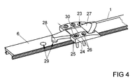
- eine weitere Ausführungsform der Fehlschaltsicherung aus
Figur 1 - Fig. 5
- eine weitere Ausführungsform der Fehlschaltsicherung aus
Figur 1 - Fig. 6
- vergrößert die Fehlschaltsicherung aus
Figur 5 - Fig. 7
- eine weitere Ausführungsform der Fehlschaltsicherung aus
Figur 1
- Fig. 8
- vergrößert die Fehlschaltsicherung aus
Figur 7
- Fig. 1
- an inventive window with a fault protection,
- Fig. 2
- an enlarged view of the fault protection
FIG. 1 , - Fig. 3
- the fault protection
FIG. 2 without bearing bracket, - Fig. 4
- another embodiment of the fault protection
FIG. 1 . - Fig. 5
- another embodiment of the fault protection
FIG. 1 . - Fig. 6
- increases the fault protection
FIG. 5 without components of a wing and a bearing block, - Fig. 7
- another embodiment of the fault protection
FIG. 1 .
- Fig. 8
- increases the fault protection
FIG. 7 without components of a wing and a bearing block.
Claims (14)
Applications Claiming Priority (1)
| Application Number | Priority Date | Filing Date | Title |
|---|---|---|---|
| DE102008000408A DE102008000408A1 (en) | 2008-02-26 | 2008-02-26 | Window or French window |
Publications (2)
| Publication Number | Publication Date |
|---|---|
| EP2103765A1 true EP2103765A1 (en) | 2009-09-23 |
| EP2103765B1 EP2103765B1 (en) | 2010-09-01 |
Family
ID=40750791
Family Applications (1)
| Application Number | Title | Priority Date | Filing Date |
|---|---|---|---|
| EP09152006A Active EP2103765B1 (en) | 2008-02-26 | 2009-02-04 | Window or window door with safety device against wrong operation |
Country Status (4)
| Country | Link |
|---|---|
| EP (1) | EP2103765B1 (en) |
| AT (1) | ATE479812T1 (en) |
| DE (2) | DE102008000408A1 (en) |
| ES (1) | ES2349457T3 (en) |
Citations (3)
| Publication number | Priority date | Publication date | Assignee | Title |
|---|---|---|---|---|
| DE1915834U (en) * | 1963-02-23 | 1965-05-13 | Hans Bilstein | MISOPERATION SAFETY FOR TILT & TURN WINDOWS, DOORS OR. DGL. PROVIDED LOCKING RODS. |
| DE2242305A1 (en) | 1972-08-28 | 1974-03-14 | Siegenia Frank Kg | STOP-FRIENDLY COMPONENT SYSTEM FOR DRIVE ROD FITTINGS |
| DE4422798C2 (en) | 1994-06-29 | 2003-10-23 | Winkhaus Fa August | Misuse protection for windows, doors or the like |
-
2008
- 2008-02-26 DE DE102008000408A patent/DE102008000408A1/en not_active Withdrawn
-
2009
- 2009-02-04 DE DE502009000080T patent/DE502009000080D1/en active Active
- 2009-02-04 AT AT09152006T patent/ATE479812T1/en active
- 2009-02-04 EP EP09152006A patent/EP2103765B1/en active Active
- 2009-02-04 ES ES09152006T patent/ES2349457T3/en active Active
Patent Citations (3)
| Publication number | Priority date | Publication date | Assignee | Title |
|---|---|---|---|---|
| DE1915834U (en) * | 1963-02-23 | 1965-05-13 | Hans Bilstein | MISOPERATION SAFETY FOR TILT & TURN WINDOWS, DOORS OR. DGL. PROVIDED LOCKING RODS. |
| DE2242305A1 (en) | 1972-08-28 | 1974-03-14 | Siegenia Frank Kg | STOP-FRIENDLY COMPONENT SYSTEM FOR DRIVE ROD FITTINGS |
| DE4422798C2 (en) | 1994-06-29 | 2003-10-23 | Winkhaus Fa August | Misuse protection for windows, doors or the like |
Also Published As
| Publication number | Publication date |
|---|---|
| DE102008000408A1 (en) | 2009-08-27 |
| DE502009000080D1 (en) | 2010-10-14 |
| ES2349457T3 (en) | 2011-01-03 |
| ATE479812T1 (en) | 2010-09-15 |
| EP2103765B1 (en) | 2010-09-01 |
Similar Documents
| Publication | Publication Date | Title |
|---|---|---|
| EP2829679B1 (en) | Fitting for pressing a sliding sash to a fixed enclosure | |
| EP3363976B1 (en) | Opening by rotation limiting arrangement for a window or a door for limiting the rotation of a leaf of a window or a door | |
| EP2103765B1 (en) | Window or window door with safety device against wrong operation | |
| DE19521601C1 (en) | Window, door or the like | |
| EP3237708B1 (en) | Fitting for installing between a sash/leaf and a fixed frame of a window, a door or the like, and window, door or the like having such a fitting | |
| EP2772604A2 (en) | Opening restrictor | |
| EP3183408B1 (en) | Control element for a fitting arrangement | |
| EP3211165A1 (en) | Checking device for a tilt-and-turn wing of a window or a door for motor-driven tilting and manual turning and tilting | |
| EP2341206A2 (en) | Corner bearing of the wing of a window pivotable against a frame and window with such a corner bearing | |
| EP2107194A1 (en) | Device for limiting the opening of a window or door | |
| EP2096247B1 (en) | Safety device against wrong operation for the fitting of a window or a door | |
| EP1965010B1 (en) | Drive device | |
| EP2871306B1 (en) | Assembly with a locking bar fitting on a frame construction | |
| EP1421245B1 (en) | Safety device for preventing the incorrect operation of connecting rod fittings | |
| EP1498563B1 (en) | Device for providing a ventilation gap | |
| EP1231345B1 (en) | Controlled locking device and corner guide | |
| DE3342661A1 (en) | Espagnolette fitting | |
| EP2602413B1 (en) | Locking equipment for locking a window or door shutter | |
| EP1790811B1 (en) | Locking device for a pivoting and tiltable fitting | |
| EP3626918B1 (en) | Fitting for a window, window | |
| EP2348176B1 (en) | Locking unit of an espagnolette fitting | |
| EP1122389B1 (en) | Pull-in device for moving a wing | |
| EP2330265B1 (en) | Safety device against wrong operation for an espagnolette fitting | |
| EP2816184B1 (en) | Corner guide for an espagnolette fitting | |
| DE202023102623U1 (en) | espagnolette fitting |
Legal Events
| Date | Code | Title | Description |
|---|---|---|---|
| PUAI | Public reference made under article 153(3) epc to a published international application that has entered the european phase |
Free format text: ORIGINAL CODE: 0009012 |
|
| AK | Designated contracting states |
Kind code of ref document: A1 Designated state(s): AT BE BG CH CY CZ DE DK EE ES FI FR GB GR HR HU IE IS IT LI LT LU LV MC MK MT NL NO PL PT RO SE SI SK TR |
|
| AX | Request for extension of the european patent |
Extension state: AL BA RS |
|
| 17P | Request for examination filed |
Effective date: 20100112 |
|
| GRAP | Despatch of communication of intention to grant a patent |
Free format text: ORIGINAL CODE: EPIDOSNIGR1 |
|
| AKX | Designation fees paid |
Designated state(s): AT BE BG CH CY CZ DE DK EE ES FI FR GB GR HR HU IE IS IT LI LT LU LV MC MK MT NL NO PL PT RO SE SI SK TR |
|
| AXX | Extension fees paid |
Extension state: RS Payment date: 20100112 Extension state: BA Payment date: 20100112 Extension state: AL Payment date: 20100112 |
|
| GRAS | Grant fee paid |
Free format text: ORIGINAL CODE: EPIDOSNIGR3 |
|
| GRAA | (expected) grant |
Free format text: ORIGINAL CODE: 0009210 |
|
| AK | Designated contracting states |
Kind code of ref document: B1 Designated state(s): AT BE BG CH CY CZ DE DK EE ES FI FR GB GR HR HU IE IS IT LI LT LU LV MC MK MT NL NO PL PT RO SE SI SK TR |
|
| AX | Request for extension of the european patent |
Extension state: AL BA RS |
|
| REG | Reference to a national code |
Ref country code: GB Ref legal event code: FG4D Free format text: NOT ENGLISH |
|
| REG | Reference to a national code |
Ref country code: CH Ref legal event code: EP |
|
| REG | Reference to a national code |
Ref country code: IE Ref legal event code: FG4D Free format text: LANGUAGE OF EP DOCUMENT: GERMAN |
|
| REF | Corresponds to: |
Ref document number: 502009000080 Country of ref document: DE Date of ref document: 20101014 Kind code of ref document: P |
|
| REG | Reference to a national code |
Ref country code: NL Ref legal event code: VDEP Effective date: 20100901 |
|
| REG | Reference to a national code |
Ref country code: ES Ref legal event code: FG2A Effective date: 20101220 |
|
| PG25 | Lapsed in a contracting state [announced via postgrant information from national office to epo] |
Ref country code: NO Free format text: LAPSE BECAUSE OF FAILURE TO SUBMIT A TRANSLATION OF THE DESCRIPTION OR TO PAY THE FEE WITHIN THE PRESCRIBED TIME-LIMIT Effective date: 20101201 Ref country code: FI Free format text: LAPSE BECAUSE OF FAILURE TO SUBMIT A TRANSLATION OF THE DESCRIPTION OR TO PAY THE FEE WITHIN THE PRESCRIBED TIME-LIMIT Effective date: 20100901 Ref country code: LT Free format text: LAPSE BECAUSE OF FAILURE TO SUBMIT A TRANSLATION OF THE DESCRIPTION OR TO PAY THE FEE WITHIN THE PRESCRIBED TIME-LIMIT Effective date: 20100901 |
|
| LTIE | Lt: invalidation of european patent or patent extension |
Effective date: 20100901 |
|
| PG25 | Lapsed in a contracting state [announced via postgrant information from national office to epo] |
Ref country code: CY Free format text: LAPSE BECAUSE OF FAILURE TO SUBMIT A TRANSLATION OF THE DESCRIPTION OR TO PAY THE FEE WITHIN THE PRESCRIBED TIME-LIMIT Effective date: 20100901 Ref country code: SI Free format text: LAPSE BECAUSE OF FAILURE TO SUBMIT A TRANSLATION OF THE DESCRIPTION OR TO PAY THE FEE WITHIN THE PRESCRIBED TIME-LIMIT Effective date: 20100901 Ref country code: PL Free format text: LAPSE BECAUSE OF FAILURE TO SUBMIT A TRANSLATION OF THE DESCRIPTION OR TO PAY THE FEE WITHIN THE PRESCRIBED TIME-LIMIT Effective date: 20100901 Ref country code: HR Free format text: LAPSE BECAUSE OF FAILURE TO SUBMIT A TRANSLATION OF THE DESCRIPTION OR TO PAY THE FEE WITHIN THE PRESCRIBED TIME-LIMIT Effective date: 20100901 |
|
| REG | Reference to a national code |
Ref country code: IE Ref legal event code: FD4D |
|
| PG25 | Lapsed in a contracting state [announced via postgrant information from national office to epo] |
Ref country code: NL Free format text: LAPSE BECAUSE OF FAILURE TO SUBMIT A TRANSLATION OF THE DESCRIPTION OR TO PAY THE FEE WITHIN THE PRESCRIBED TIME-LIMIT Effective date: 20100901 Ref country code: SE Free format text: LAPSE BECAUSE OF FAILURE TO SUBMIT A TRANSLATION OF THE DESCRIPTION OR TO PAY THE FEE WITHIN THE PRESCRIBED TIME-LIMIT Effective date: 20100901 Ref country code: GR Free format text: LAPSE BECAUSE OF FAILURE TO SUBMIT A TRANSLATION OF THE DESCRIPTION OR TO PAY THE FEE WITHIN THE PRESCRIBED TIME-LIMIT Effective date: 20101202 Ref country code: LV Free format text: LAPSE BECAUSE OF FAILURE TO SUBMIT A TRANSLATION OF THE DESCRIPTION OR TO PAY THE FEE WITHIN THE PRESCRIBED TIME-LIMIT Effective date: 20100901 |
|
| PG25 | Lapsed in a contracting state [announced via postgrant information from national office to epo] |
Ref country code: IE Free format text: LAPSE BECAUSE OF FAILURE TO SUBMIT A TRANSLATION OF THE DESCRIPTION OR TO PAY THE FEE WITHIN THE PRESCRIBED TIME-LIMIT Effective date: 20100901 |
|
| PG25 | Lapsed in a contracting state [announced via postgrant information from national office to epo] |
Ref country code: CZ Free format text: LAPSE BECAUSE OF FAILURE TO SUBMIT A TRANSLATION OF THE DESCRIPTION OR TO PAY THE FEE WITHIN THE PRESCRIBED TIME-LIMIT Effective date: 20100901 Ref country code: RO Free format text: LAPSE BECAUSE OF FAILURE TO SUBMIT A TRANSLATION OF THE DESCRIPTION OR TO PAY THE FEE WITHIN THE PRESCRIBED TIME-LIMIT Effective date: 20100901 Ref country code: IS Free format text: LAPSE BECAUSE OF FAILURE TO SUBMIT A TRANSLATION OF THE DESCRIPTION OR TO PAY THE FEE WITHIN THE PRESCRIBED TIME-LIMIT Effective date: 20110101 Ref country code: PT Free format text: LAPSE BECAUSE OF FAILURE TO SUBMIT A TRANSLATION OF THE DESCRIPTION OR TO PAY THE FEE WITHIN THE PRESCRIBED TIME-LIMIT Effective date: 20110103 Ref country code: EE Free format text: LAPSE BECAUSE OF FAILURE TO SUBMIT A TRANSLATION OF THE DESCRIPTION OR TO PAY THE FEE WITHIN THE PRESCRIBED TIME-LIMIT Effective date: 20100901 Ref country code: SK Free format text: LAPSE BECAUSE OF FAILURE TO SUBMIT A TRANSLATION OF THE DESCRIPTION OR TO PAY THE FEE WITHIN THE PRESCRIBED TIME-LIMIT Effective date: 20100901 |
|
| PLBE | No opposition filed within time limit |
Free format text: ORIGINAL CODE: 0009261 |
|
| STAA | Information on the status of an ep patent application or granted ep patent |
Free format text: STATUS: NO OPPOSITION FILED WITHIN TIME LIMIT |
|
| 26N | No opposition filed |
Effective date: 20110606 |
|
| PG25 | Lapsed in a contracting state [announced via postgrant information from national office to epo] |
Ref country code: DK Free format text: LAPSE BECAUSE OF FAILURE TO SUBMIT A TRANSLATION OF THE DESCRIPTION OR TO PAY THE FEE WITHIN THE PRESCRIBED TIME-LIMIT Effective date: 20100901 |
|
| PG25 | Lapsed in a contracting state [announced via postgrant information from national office to epo] |
Ref country code: MC Free format text: LAPSE BECAUSE OF NON-PAYMENT OF DUE FEES Effective date: 20110228 |
|
| REG | Reference to a national code |
Ref country code: DE Ref legal event code: R097 Ref document number: 502009000080 Country of ref document: DE Effective date: 20110606 |
|
| REG | Reference to a national code |
Ref country code: FR Ref legal event code: ST Effective date: 20111102 |
|
| PG25 | Lapsed in a contracting state [announced via postgrant information from national office to epo] |
Ref country code: MT Free format text: LAPSE BECAUSE OF FAILURE TO SUBMIT A TRANSLATION OF THE DESCRIPTION OR TO PAY THE FEE WITHIN THE PRESCRIBED TIME-LIMIT Effective date: 20100901 |
|
| PG25 | Lapsed in a contracting state [announced via postgrant information from national office to epo] |
Ref country code: FR Free format text: LAPSE BECAUSE OF NON-PAYMENT OF DUE FEES Effective date: 20110228 |
|
| PG25 | Lapsed in a contracting state [announced via postgrant information from national office to epo] |
Ref country code: MK Free format text: LAPSE BECAUSE OF FAILURE TO SUBMIT A TRANSLATION OF THE DESCRIPTION OR TO PAY THE FEE WITHIN THE PRESCRIBED TIME-LIMIT Effective date: 20100901 |
|
| PG25 | Lapsed in a contracting state [announced via postgrant information from national office to epo] |
Ref country code: LU Free format text: LAPSE BECAUSE OF NON-PAYMENT OF DUE FEES Effective date: 20110204 |
|
| PG25 | Lapsed in a contracting state [announced via postgrant information from national office to epo] |
Ref country code: BG Free format text: LAPSE BECAUSE OF FAILURE TO SUBMIT A TRANSLATION OF THE DESCRIPTION OR TO PAY THE FEE WITHIN THE PRESCRIBED TIME-LIMIT Effective date: 20101201 |
|
| REG | Reference to a national code |
Ref country code: CH Ref legal event code: PL |
|
| GBPC | Gb: european patent ceased through non-payment of renewal fee |
Effective date: 20130204 |
|
| PG25 | Lapsed in a contracting state [announced via postgrant information from national office to epo] |
Ref country code: CH Free format text: LAPSE BECAUSE OF NON-PAYMENT OF DUE FEES Effective date: 20130228 Ref country code: LI Free format text: LAPSE BECAUSE OF NON-PAYMENT OF DUE FEES Effective date: 20130228 Ref country code: HU Free format text: LAPSE BECAUSE OF FAILURE TO SUBMIT A TRANSLATION OF THE DESCRIPTION OR TO PAY THE FEE WITHIN THE PRESCRIBED TIME-LIMIT Effective date: 20100901 |
|
| PG25 | Lapsed in a contracting state [announced via postgrant information from national office to epo] |
Ref country code: GB Free format text: LAPSE BECAUSE OF NON-PAYMENT OF DUE FEES Effective date: 20130204 |
|
| PGFP | Annual fee paid to national office [announced via postgrant information from national office to epo] |
Ref country code: TR Payment date: 20140115 Year of fee payment: 6 Ref country code: ES Payment date: 20140321 Year of fee payment: 6 Ref country code: IT Payment date: 20140220 Year of fee payment: 6 |
|
| PGFP | Annual fee paid to national office [announced via postgrant information from national office to epo] |
Ref country code: BE Payment date: 20140327 Year of fee payment: 6 |
|
| PGFP | Annual fee paid to national office [announced via postgrant information from national office to epo] |
Ref country code: AT Payment date: 20150225 Year of fee payment: 7 |
|
| PG25 | Lapsed in a contracting state [announced via postgrant information from national office to epo] |
Ref country code: BE Free format text: LAPSE BECAUSE OF NON-PAYMENT OF DUE FEES Effective date: 20150228 |
|
| PG25 | Lapsed in a contracting state [announced via postgrant information from national office to epo] |
Ref country code: IT Free format text: LAPSE BECAUSE OF NON-PAYMENT OF DUE FEES Effective date: 20150204 |
|
| REG | Reference to a national code |
Ref country code: AT Ref legal event code: MM01 Ref document number: 479812 Country of ref document: AT Kind code of ref document: T Effective date: 20160204 |
|
| PG25 | Lapsed in a contracting state [announced via postgrant information from national office to epo] |
Ref country code: AT Free format text: LAPSE BECAUSE OF NON-PAYMENT OF DUE FEES Effective date: 20160204 |
|
| REG | Reference to a national code |
Ref country code: ES Ref legal event code: FD2A Effective date: 20170405 |
|
| PG25 | Lapsed in a contracting state [announced via postgrant information from national office to epo] |
Ref country code: ES Free format text: LAPSE BECAUSE OF NON-PAYMENT OF DUE FEES Effective date: 20160205 |
|
| PG25 | Lapsed in a contracting state [announced via postgrant information from national office to epo] |
Ref country code: TR Free format text: LAPSE BECAUSE OF NON-PAYMENT OF DUE FEES Effective date: 20150204 |
|
| PGFP | Annual fee paid to national office [announced via postgrant information from national office to epo] |
Ref country code: DE Payment date: 20230216 Year of fee payment: 15 |
|
| P01 | Opt-out of the competence of the unified patent court (upc) registered |
Effective date: 20230515 |