EP2103763B1 - Tubular handle for doors and windows - Google Patents
Tubular handle for doors and windows Download PDFInfo
- Publication number
- EP2103763B1 EP2103763B1 EP20090155465 EP09155465A EP2103763B1 EP 2103763 B1 EP2103763 B1 EP 2103763B1 EP 20090155465 EP20090155465 EP 20090155465 EP 09155465 A EP09155465 A EP 09155465A EP 2103763 B1 EP2103763 B1 EP 2103763B1
- Authority
- EP
- European Patent Office
- Prior art keywords
- tubular body
- tubular
- boss piece
- hole
- track
- Prior art date
- Legal status (The legal status is an assumption and is not a legal conclusion. Google has not performed a legal analysis and makes no representation as to the accuracy of the status listed.)
- Not-in-force
Links
Images

Classifications
-
- E—FIXED CONSTRUCTIONS
- E05—LOCKS; KEYS; WINDOW OR DOOR FITTINGS; SAFES
- E05B—LOCKS; ACCESSORIES THEREFOR; HANDCUFFS
- E05B1/00—Knobs or handles for wings; Knobs, handles, or press buttons for locks or latches on wings
- E05B1/0015—Knobs or handles which do not operate the bolt or lock, e.g. non-movable; Mounting thereof
Definitions
- the present invention relates to a tubular handle for doors and windows according to the preamble of the main claim.
- the handle in question is classifiable within the industrial sector relating to the production of accessories for doors and windows and is intended to be mounted via fixing means on the sidewalls of doors and windows or on the leaves of doors, main entrances doors, French windows, windows or the like, formed by profiles made of metal, PVC or other materials.
- the boss piece B is mechanically mounted by means of screwing onto one end of the tubular body C of the handle D.
- the projecting part E consists of a threaded rod which passes through the profile F from one sidewall to the other through two holes which are aligned with each other, bearing against an end body N on one sidewall of the profile F and engaging in a locking manner with the ring nut G on the opposite sidewall.
- the threaded rod E has, screwed onto its free end, a pin H which has an annular recess I for insertion of a locking grub screw L inserted inside a first through-hole formed in the tubular end C of the handle D and inside a second through-hole aligned with the first hole formed in the boss piece B.
- the fixing means for the handles currently available on the market therefore usually require, in accordance with the above description, the provision of two holes formed in the two opposite sidewalls of the door or window. This is obviously to the detriment of the general aesthetic appearance of the door or window since the latter also has a hole in the sidewall not intended to receive the handle, such as that the threaded screw is visible from the exterior.
- the handles formed by a single tubular body with its ends bent and directed towards the sidewall of the door or window use boss pieces which are fixed by means of screwing onto the ends of the tubular body of the handle.
- the ends of the tubular body must be internally machined in order to form the inner threads needed to ensure engagement with the corresponding outer threads provided on the boss pieces.
- Locking of the handle to the door or window is performed by means of a grub screw which engages, passing through a hole formed in the end of the tubular body and in the boss piece, with a pin snugly fitted inside the boss piece and screwed onto the threaded rod fastened to the door or window.
- a drawback of the handles of the known type described above consists in the laborious machining which must be performed at the ends of the tubular body in order to form internally the threading for engagement with the boss piece. Furthermore, the need to provide internal threading at the ends of the tubular body of the handle requires the use of sufficiently large thicknesses of the tubular body in order to be able to provide the threading inside the tubular body by means of cutting and stock-removal.
- Handles with a tubular body formed as one piece are known, said handles housing, at each end of the tubular body, a boss piece which has a projecting sliding element which engages inside a track formed in the boss piece. The latter is then retained by means of a through grub screw engaging inside aligned holes formed in the tubular body and in the boss piece.
- Document EP 1695647 discloses a gripping or supporting element, comprising a shaped body provided with ends connected to a bearing structure, bushes applied to the bearing structure through first fastening means that project from the outer surface of the bearing structure and second fastening means that permanently connect said shaped body to the bushes.
- the gripping or supporting element comprises shaped inserts joined to the ends of the shaped body through third fastening means, said inserts being coupled to the bushes when the shaped body is positioned against the bearing structure.
- handles comprising a tubular gripping body connected to the door or window by two tubular spacer members which are fixed at right angles to the tubular gripping member.
- the spacing members are fixed to the tubular gripping part by means of a tie rod with its head fastened to the boss piece and its shank engaged inside a threaded hole formed in the tubular gripping body of the handle.
- the boss piece is automatically fixed to the end of the spacers so as to then be fastened in a conventional manner using a pin and grub screw to the threaded rod rigidly fastened to the door or window.
- boss piece must be firmly secured to the tubular body of the handle since it must be able to withstand the numerous mechanical stresses arising from opening and closing of the door or window using the handle grip.
- the object of the present invention is to eliminate the drawbacks of the above-mentioned prior art by providing a tubular handle for doors and windows which may be easily fixed to the sidewalls of the doors and windows and which is operationally entirely reliable.
- Another object of the present invention is to provide a tubular handle for doors and windows which is simple and inexpensive to produce.
- the fixture F may be of any type such as, for example a window, door, French windows or a main entrance door and may be formed with profiles made of metal, PVC or other materials.
- the handle 1 comprises a shaped tubular body 3 made of plastic or preferably metallic material such as, for example, aluminium, formed, in accordance with the example of embodiment shown in Figures 1 to 3 , as a single piece with a gripping portion 3' connected continuously to two end portions 3" directed towards the sidewall P of the door or window to which they are to be connected.
- the gripping and end portions are formed as a single piece, for example by means of moulding or bending.
- the fastening device 1 comprises a threaded rod 4 which is fixed at right angles to the sidewall P of the door or window F and has a projecting portion 5 intended to be fixed to the handle 1.
- the threaded rod 4 may be fixed to the door or window in a manner conventional per se, as for example described in the patent PD2005A000238 in the name of the same applicant, or may be fixed by inserting the rod 4 inside a through-hole in the sidewall P such that the head 6 is kept in contact against a first face of the sidewall of the door or window by means of a nut screwed onto the opposite face of the same sidewall P.
- the fixing means 2 are preferably designed in an identical manner for each end 8 of the tubular body 3 and comprise two metal boss pieces 7 with a substantially cylindrical form provided internally with a coaxial seat 9 and each able to be engaged mechanically inside one end of the tubular body 3.
- a pin 10 can be screwed onto the free end of the threaded rod 4, being provided for this purpose with a counter-threaded coaxial hole.
- the pin 10 is screwed so as to keep the rod 4 rigidly fixed to the sidewall P of the door or window F, if necessary with the aid of a washer or flat insert 25.
- the end of said pin directed towards the sidewall P has a hexagonal shaped widened base for engagement with an operating tool, usually consisting of a spanner.
- the pin 10 can be mechanically connected with a form fit to the inner seat 9 of the boss piece 7.
- the pin 10 is furthermore fixed to the boss piece 7 by means of a grub screw 11 passing through a first threaded hole 12 formed in the thickness of the tubular body 3 at its end 8 and a second threaded hole 13 aligned with the first hole 12 and formed in the boss piece 7 so that the grub screw reaches the inner coaxial seat 9 housing the pin 10 and engages inside an annular recess 14 of the latter.
- the tapered shape of the recess 14 and the corresponding tip 15 of the grub screw 11 allow, when engaged in contact with each other, the handle 1 to be forced against the sidewall of the door or window F.
- the end of the pin 10 intended to come into contact against the sidewall P of the door or window F is also provided with a hexagonal shaped widened base for fitting an operating tool such as, for example, a spanner, during assembly of the device 1 on the door or window F.
- the fixing means 2 furthermore comprise a sliding element 16 projecting from the inner surface of the tubular body 3 and engaging inside a track 17 formed externally on the boss piece 7 with an end-of-travel stop 18 where the first hole and the second hole 13 are aligned with each other.
- the sliding element 16 acts transversely against the walls of the track 17, producing the mechanical resistance necessary to ensure securing of the boss piece 7 to the tubular body 3.
- the sliding element 16 is in the form of an annular projection provided around the first hole 12, as indicated in the cross-section of Figure 3 formed diametrically through said hole 12, and is obtained by means of punching or moulding of the tubular body 3.
- the second hole 13 is provided at the end of the track 17 so that, when the sliding element 16 reaches the end-of-travel stop 18, the two holes 12, 13 are aligned.
- the track 17 extends with one portion 17', directed in an axial direction along the axis of the boss piece 7 so as to allow insertion of the latter inside the tubular body 3, and with one portion 17" directed circumferentially, i.e. transversely with respect to the axial direction so as to help constrain mechanically the boss piece 7 to the tubular body 3.
- the above-mentioned track 17 has a first longitudinal section 17', arranged parallel along the axis of the boss piece 7, and a second section 17", extending along a circumference of the boss piece 7 from the inner end of the longitudinal section 17'.
- the track thereby assumes an L shape which offers numerous advantages.
- the first longitudinal section 17" is intended for insertion of the boss piece 7 inside the tubular body 3 until it reaches a slightly inset position so as to avoid coming into contact with the glass sidewall P of the door when the handle is mounted.
- the second circumferential section 17" exerts a reactive force perpendicular to that exerted by operation of the handle and transmitted by the grub screw and the projecting sliding element 16.
- the second circumferential section 17" performs the function of retaining the boss piece 7 inside the tubular body 3.
- At least one projecting nib 60 is provided in the vicinity of the end-of-travel stop 18 of the second circumferential section 17" of the track, said nib being able to be deformed by the passing movement of the projecting sliding element 16 when the boss piece 7 is forcibly inserted inside the tubular body 3.
- two opposite nibs are provided on the sides of the track 17 as shown in Figure 4 .
- the projecting sliding element 16 is retained in the end-of-travel position 18, allowing the elimination of play and preventing the boss piece 7 from coming out of the tubular body 3 during assembly.
- force may be applied using a spanner engaged on the hexagonal shaped portion of the coaxial seat 9.
- the tubular body 3 is formed by a column, in particular with a straight shape, acting as a grip 3', and with two or more end portions 3" acting as spacers for fixing, at a distance, the straight column onto the sidewall P of the door or window.
- the two spacers 3" have a first, circular, end profile and a second, shaped, end profile for resting against the outer surface of the column 3'.
- Each spacer 3" is fixed to the column 3' by means of a screw 61 which has its shank 62 inserted inside a through-hole 63 formed on the boss piece 7 and its head 64 bearing against a shoulder 65 formed on the bottom of the coaxial seat 9.
- the end of the shank 62 of the screw 61 engages inside a female thread 66 integral with the column 3' and preferably formed by an internally threaded bush welded so as to project from the outer surface of the said column 3'.
- the invention thus conceived therefore achieves the predefined objects.
Description
- The present invention relates to a tubular handle for doors and windows according to the preamble of the main claim.
- The handle in question is classifiable within the industrial sector relating to the production of accessories for doors and windows and is intended to be mounted via fixing means on the sidewalls of doors and windows or on the leaves of doors, main entrances doors, French windows, windows or the like, formed by profiles made of metal, PVC or other materials.
- At present, as is known, numerous different mechanical solutions for fixing handles of the tubular type to the sidewalls of doors and windows are commercially available. These solutions generally have in common the fact that they envisage a part which projects from the sidewall of the door or window on which the handle is to be fixed and which is fastened to the said sidewall usually by means of a nut (or washer). A metal boss piece is engaged on the latter by means of a grub screw and rigidly fastened to the handle using suitable fixing means.
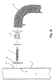
- According to a very common constructional form, shown in the accompanying Figure A, the boss piece B is mechanically mounted by means of screwing onto one end of the tubular body C of the handle D. In greater detail, the projecting part E consists of a threaded rod which passes through the profile F from one sidewall to the other through two holes which are aligned with each other, bearing against an end body N on one sidewall of the profile F and engaging in a locking manner with the ring nut G on the opposite sidewall. The threaded rod E has, screwed onto its free end, a pin H which has an annular recess I for insertion of a locking grub screw L inserted inside a first through-hole formed in the tubular end C of the handle D and inside a second through-hole aligned with the first hole formed in the boss piece B.
- The fixing means for the handles currently available on the market therefore usually require, in accordance with the above description, the provision of two holes formed in the two opposite sidewalls of the door or window. This is obviously to the detriment of the general aesthetic appearance of the door or window since the latter also has a hole in the sidewall not intended to receive the handle, such as that the threaded screw is visible from the exterior.
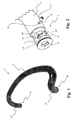
- In order to overcome this drawback, more recently a handle has been devised, as described in the application PD2005A000238 in the name of the same applicant and shown in the accompanying
Figure B , provided with fixing means comprising a retaining element R which can be connected to the threaded rod E and can be inserted inside the door or window F through a hole M so as to bear against the inner face Pi of the sidewall P and thus retain the threaded rod E against the sidewall P. - The aforementioned handle design, while solving the above aesthetic problem associated with the formation of a hole in the fixture, has proved in practice to be not without certain drawbacks.
- In fact, at present, the handles formed by a single tubular body with its ends bent and directed towards the sidewall of the door or window use boss pieces which are fixed by means of screwing onto the ends of the tubular body of the handle. For this purpose, the ends of the tubular body must be internally machined in order to form the inner threads needed to ensure engagement with the corresponding outer threads provided on the boss pieces.
- Locking of the handle to the door or window is performed by means of a grub screw which engages, passing through a hole formed in the end of the tubular body and in the boss piece, with a pin snugly fitted inside the boss piece and screwed onto the threaded rod fastened to the door or window.
- A drawback of the handles of the known type described above consists in the laborious machining which must be performed at the ends of the tubular body in order to form internally the threading for engagement with the boss piece. Furthermore, the need to provide internal threading at the ends of the tubular body of the handle requires the use of sufficiently large thicknesses of the tubular body in order to be able to provide the threading inside the tubular body by means of cutting and stock-removal.
- Handles with a tubular body formed as one piece are known, said handles housing, at each end of the tubular body, a boss piece which has a projecting sliding element which engages inside a track formed in the boss piece. The latter is then retained by means of a through grub screw engaging inside aligned holes formed in the tubular body and in the boss piece. This solution, while overcoming many of the drawbacks of the currently known art, is not easy to use owing to the not particularly well-designed form of the track which does not allow optimum retention of the boss piece on the tubular body in particular during assembly.
- Document
EP 1695647 discloses a gripping or supporting element, comprising a shaped body provided with ends connected to a bearing structure, bushes applied to the bearing structure through first fastening means that project from the outer surface of the bearing structure and second fastening means that permanently connect said shaped body to the bushes. The gripping or supporting element comprises shaped inserts joined to the ends of the shaped body through third fastening means, said inserts being coupled to the bushes when the shaped body is positioned against the bearing structure. - Also known are handles comprising a tubular gripping body connected to the door or window by two tubular spacer members which are fixed at right angles to the tubular gripping member. In this case, the spacing members are fixed to the tubular gripping part by means of a tie rod with its head fastened to the boss piece and its shank engaged inside a threaded hole formed in the tubular gripping body of the handle. By means of this mechanism, the boss piece is automatically fixed to the end of the spacers so as to then be fastened in a conventional manner using a pin and grub screw to the threaded rod rigidly fastened to the door or window.
- It is important to remember that the boss piece must be firmly secured to the tubular body of the handle since it must be able to withstand the numerous mechanical stresses arising from opening and closing of the door or window using the handle grip.
- It is in fact inadvisable to rely on the grub screw alone for the mechanical strength, in particular the tractional force, since it would in fact be subject to an excessive shearing force.
- In this situation, therefore, the object of the present invention is to eliminate the drawbacks of the above-mentioned prior art by providing a tubular handle for doors and windows which may be easily fixed to the sidewalls of the doors and windows and which is operationally entirely reliable.
- Another object of the present invention is to provide a tubular handle for doors and windows which is simple and inexpensive to produce.
- The technical features of the invention, in accordance with the above-mentioned objects, may be clearly determined from the contents of the claims below and the advantages thereof will emerge more clearly from the detailed description which follows, with reference to the accompanying drawings which illustrate a purely exemplary and non-limiting embodiment thereof, where:
-
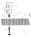
Figure 1 is a perspective view of a first embodiment of a tubular handle for doors and windows according to the invention formed as one piece; -
Figure 2 is an exploded perspective view of the handle according to the invention shown only partially and in accordance with a preferred embodiment; -
Fig. 3 shows an exploded side view of the handle shown inFigure 1 , associated with the sidewall of a door or window; -
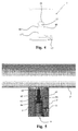
Fig. 4 shows a side view of en enlarged detail of the handle shown in the preceding Figures, relating to a boss piece; -
Figure 5 shows a cross-sectional view of a second embodiment of a tubular handle for doors and windows according to the invention, shown only partially and with the tubular body formed by a column and spacers; - With reference to the accompanying drawings 1 denotes in its entirety a tubular handle for doors and windows, according to the present invention.
- It is intended to be mounted on a door or window F, typically on the sidewall P of a door in particular made of glass, using fixing means generically indicated by 2.
- Obviously, without thereby departing from the scope of protection of this patent, the fixture F may be of any type such as, for example a window, door, French windows or a main entrance door and may be formed with profiles made of metal, PVC or other materials.
- The handle 1 comprises a shaped
tubular body 3 made of plastic or preferably metallic material such as, for example, aluminium, formed, in accordance with the example of embodiment shown inFigures 1 to 3 , as a single piece with a gripping portion 3' connected continuously to twoend portions 3" directed towards the sidewall P of the door or window to which they are to be connected. The gripping and end portions are formed as a single piece, for example by means of moulding or bending. - As can be seen in particular in
Figure 3 , the fastening device 1 comprises a threadedrod 4 which is fixed at right angles to the sidewall P of the door or window F and has a projectingportion 5 intended to be fixed to the handle 1. - The threaded
rod 4 may be fixed to the door or window in a manner conventional per se, as for example described in the patentPD2005A000238 rod 4 inside a through-hole in the sidewall P such that the head 6 is kept in contact against a first face of the sidewall of the door or window by means of a nut screwed onto the opposite face of the same sidewall P. - The
fixing means 2 are preferably designed in an identical manner for eachend 8 of thetubular body 3 and comprise twometal boss pieces 7 with a substantially cylindrical form provided internally with acoaxial seat 9 and each able to be engaged mechanically inside one end of thetubular body 3. - A
pin 10 can be screwed onto the free end of the threadedrod 4, being provided for this purpose with a counter-threaded coaxial hole. Thepin 10 is screwed so as to keep therod 4 rigidly fixed to the sidewall P of the door or window F, if necessary with the aid of a washer orflat insert 25. In order to fix thepin 10 rigidly to the sidewall, the end of said pin directed towards the sidewall P has a hexagonal shaped widened base for engagement with an operating tool, usually consisting of a spanner. - In turn, the
pin 10 can be mechanically connected with a form fit to theinner seat 9 of theboss piece 7. - The
pin 10 is furthermore fixed to theboss piece 7 by means of agrub screw 11 passing through a first threadedhole 12 formed in the thickness of thetubular body 3 at itsend 8 and a second threadedhole 13 aligned with thefirst hole 12 and formed in theboss piece 7 so that the grub screw reaches the innercoaxial seat 9 housing thepin 10 and engages inside anannular recess 14 of the latter. - The tapered shape of the
recess 14 and thecorresponding tip 15 of thegrub screw 11 allow, when engaged in contact with each other, the handle 1 to be forced against the sidewall of the door or window F. - The end of the
pin 10 intended to come into contact against the sidewall P of the door or window F is also provided with a hexagonal shaped widened base for fitting an operating tool such as, for example, a spanner, during assembly of the device 1 on the door or window F. - According to the present invention, the fixing means 2 furthermore comprise a sliding
element 16 projecting from the inner surface of thetubular body 3 and engaging inside atrack 17 formed externally on theboss piece 7 with an end-of-travel stop 18 where the first hole and thesecond hole 13 are aligned with each other. - The sliding
element 16 acts transversely against the walls of thetrack 17, producing the mechanical resistance necessary to ensure securing of theboss piece 7 to thetubular body 3. - Advantageously, the
sliding element 16 is in the form of an annular projection provided around thefirst hole 12, as indicated in the cross-section ofFigure 3 formed diametrically through saidhole 12, and is obtained by means of punching or moulding of thetubular body 3. Thesecond hole 13 is provided at the end of thetrack 17 so that, when thesliding element 16 reaches the end-of-travel stop 18, the twoholes - The
track 17 extends with one portion 17', directed in an axial direction along the axis of theboss piece 7 so as to allow insertion of the latter inside thetubular body 3, and with oneportion 17" directed circumferentially, i.e. transversely with respect to the axial direction so as to help constrain mechanically theboss piece 7 to thetubular body 3. - According to the present invention the above-mentioned
track 17 has a first longitudinal section 17', arranged parallel along the axis of theboss piece 7, and asecond section 17", extending along a circumference of theboss piece 7 from the inner end of the longitudinal section 17'. The track thereby assumes an L shape which offers numerous advantages. - The first
longitudinal section 17" is intended for insertion of theboss piece 7 inside thetubular body 3 until it reaches a slightly inset position so as to avoid coming into contact with the glass sidewall P of the door when the handle is mounted. - When the handle 1 is mounted with the
grubs screw 11 fixed inside theholes circumferential section 17" exerts a reactive force perpendicular to that exerted by operation of the handle and transmitted by the grub screw and the projecting slidingelement 16. During mounting of the handle 1 the secondcircumferential section 17" performs the function of retaining theboss piece 7 inside thetubular body 3. - Advantageously for this latter purpose, at least one projecting
nib 60 is provided in the vicinity of the end-of-travel stop 18 of the secondcircumferential section 17" of the track, said nib being able to be deformed by the passing movement of the projecting slidingelement 16 when theboss piece 7 is forcibly inserted inside thetubular body 3. - Preferably two opposite nibs are provided on the sides of the
track 17 as shown inFigure 4 . - Once the
nib 60 has been passed by, the projecting slidingelement 16 is retained in the end-of-travel position 18, allowing the elimination of play and preventing theboss piece 7 from coming out of thetubular body 3 during assembly. - In order to allow the
boss piece 7 to overcome thenib 60, force may be applied using a spanner engaged on the hexagonal shaped portion of thecoaxial seat 9. - This solution for retaining the
boss piece 7 inside the tubular body has proved to be simpler to realize and operationally better than other solutions already known in the art which envisage the boss piece being retained insidetubular body 3 by providing a precise interference fit achieved, for example, by designing the boss with at least one slightly conical shaped section. - In accordance with the second example of embodiment of the handle shown in
Figure 5 , thetubular body 3 is formed by a column, in particular with a straight shape, acting as a grip 3', and with two ormore end portions 3" acting as spacers for fixing, at a distance, the straight column onto the sidewall P of the door or window. - The two
spacers 3" have a first, circular, end profile and a second, shaped, end profile for resting against the outer surface of the column 3'. - Each
spacer 3" is fixed to the column 3' by means of ascrew 61 which has itsshank 62 inserted inside a through-hole 63 formed on theboss piece 7 and itshead 64 bearing against ashoulder 65 formed on the bottom of thecoaxial seat 9. The end of theshank 62 of thescrew 61 engages inside afemale thread 66 integral with the column 3' and preferably formed by an internally threaded bush welded so as to project from the outer surface of the said column 3'. - The invention thus conceived therefore achieves the predefined objects.
- All the details may be replaced by technically equivalent elements and the dimensions, the forms and the materials used may be of any nature according to requirements, always without departing from the scope of the invention as defined by the appended claims.
Claims (7)
- Tubular handle (1) for doors and windows, comprising a tubular support body (3) for gripping the handle, fixing means (2) able to connect mechanically at least one end (8) of said tubular body (3) to a door or window, directed towards said door or window (F), said fixing means (2) comprising:- at least one threaded rod (4) intended to be fixed to said door or window (F);- at least one boss piece (7) which can be mechanically engaged on said at least one end (8) of said tubular body (3);- at least one pin (10) which can be engaged by means of screwing onto said threaded rod (4), can be inserted inside a coaxial seat (9) of said boss piece (7) and can be mechanically constrained to said boss piece (7) by means of a grub screw (11) passing through a first hole (12) formed in said tubular body (3) and a second hole (13) aligned with the first hole (12) and formed in said boss piece (7), so as to be inserted inside a recess (14) of said pin (10);- a sliding element (16) projecting from the inner surface of said tubular body (3) and engaging inside a track (17) formed externally on said boss piece (7);
characterized in that said track (17) is provided with an end-of-travel stop (18) where said first (12) and second holes (13) are aligned with each other, said track (17) extending with a substantially L-shaped form having a first section (17') directed in an axial direction along said boss piece (7), so as to allow the latter to be inserted inside said tubular body (3), and with at least one second section (17") directed circumferentially or transversely relative to said axial direction so as to help constrain mechanically said boss piece (7) to said tubular body (3). - Tubular handle according to Claim 1, wherein said sliding element (16) is in the form of a substantially annular projection provided around said first hole (12).
- Tubular handle according to any one of the preceding claims, wherein said second hole (13) is provided at the end of said track (17).
- Tubular handle according to Claim 1, wherein said sliding element (16) is formed by means of punching or moulding of said tubular body (3).
- Tubular handle according to Claim 1, wherein a projecting nib (60) is provided in the vicinity of the end-of-travel stop (18) of the second circumferential section (17") of said track (17), said nib (60) being able to be deformed by the passing movement of the projecting sliding element (16) when the boss piece (7) is forcibly inserted inside the tubular body (3).
- Tubular handle according to Claim 5, wherein the projecting sliding element (16), once it has passed over the nib (60), is retained by the latter against the end-of-travel stop (18) so as to eliminate the play and prevent, during assembly of said handle, said boss piece (7) from coming out of said tubular body (3).
- Tubular handle according to Claim 1, wherein the tubular body (3) is formed by a column, in particular a straight column, acting as a grip (3") and with two or more separate end portions (3') acting as spacers, each of them being fixed to said column by means of a screw (61) with a shank (62) inserted inside a through-hole (63) formed axially in the boss piece (7) and engaging inside a female thread (66) integral with said column, and with a head (64) arranged so as to bear against a shoulder (65) formed on the bottom of the coaxial seat (9) of said boss piece (7).
Applications Claiming Priority (1)
| Application Number | Priority Date | Filing Date | Title |
|---|---|---|---|
| ITPD20080091 ITPD20080091A1 (en) | 2008-03-21 | 2008-03-21 | TUBULAR HANDLE FOR WINDOWS |
Publications (3)
| Publication Number | Publication Date |
|---|---|
| EP2103763A2 EP2103763A2 (en) | 2009-09-23 |
| EP2103763A3 EP2103763A3 (en) | 2010-05-26 |
| EP2103763B1 true EP2103763B1 (en) | 2012-05-16 |
Family
ID=40293084
Family Applications (1)
| Application Number | Title | Priority Date | Filing Date |
|---|---|---|---|
| EP20090155465 Not-in-force EP2103763B1 (en) | 2008-03-21 | 2009-03-18 | Tubular handle for doors and windows |
Country Status (2)
| Country | Link |
|---|---|
| EP (1) | EP2103763B1 (en) |
| IT (1) | ITPD20080091A1 (en) |
Families Citing this family (2)
| Publication number | Priority date | Publication date | Assignee | Title |
|---|---|---|---|---|
| KR101408400B1 (en) | 2013-04-05 | 2014-06-17 | 김동진 | A door handle |
| US11719019B2 (en) * | 2020-12-01 | 2023-08-08 | Kohler Co. | Handle assembly for a shower door |
Family Cites Families (3)
| Publication number | Priority date | Publication date | Assignee | Title |
|---|---|---|---|---|
| DE3518127C2 (en) * | 1985-05-21 | 1994-02-17 | Grimberg Hans Edelstahl | Handle fastening system |
| DE202004018872U1 (en) * | 2004-12-07 | 2005-04-14 | Elram Wintergartentechnik Gmbh | Door handle has at predetermined intervals sockets for external handle fixing bolt with one socket having distance adjusting device to compensate different spacing between fixing bolt and socket |
| ITVI20050051A1 (en) | 2005-02-24 | 2006-08-25 | Primo Roberto Malini | ELEMENT OF GRIP OR SUPPORT |
-
2008
- 2008-03-21 IT ITPD20080091 patent/ITPD20080091A1/en unknown
-
2009
- 2009-03-18 EP EP20090155465 patent/EP2103763B1/en not_active Not-in-force
Also Published As
| Publication number | Publication date |
|---|---|
| EP2103763A3 (en) | 2010-05-26 |
| EP2103763A2 (en) | 2009-09-23 |
| ITPD20080091A1 (en) | 2009-09-22 |
Similar Documents
| Publication | Publication Date | Title |
|---|---|---|
| US6286185B1 (en) | Hinge for metal cupboard doors | |
| EP3313236B1 (en) | Joining device, particularly for joining a shelf to a wall of a piece of furniture | |
| US7331358B2 (en) | Device for fixing a tap handle | |
| US20090263180A1 (en) | Device for securing an add-on and a support in spaced-apart relation | |
| US9267310B2 (en) | Handle assembly for double-walled door | |
| US8087685B2 (en) | Securing device for head tube bearings, and method for securing head tube bearings | |
| EP3271530B1 (en) | Holding element for a door or window handle and arrangement of a door or window handle on a receiving opening of a window frame, a door leaf or the like | |
| EP2206856B1 (en) | Actuation handle | |
| EP2103763B1 (en) | Tubular handle for doors and windows | |
| EP1022413B1 (en) | Mounting plate | |
| US7389715B1 (en) | Pliers-type hand tool | |
| WO2019193559A1 (en) | Screwless handle unit for a door | |
| EP2705260B1 (en) | Coupling device for furniture and furnishing articles | |
| KR20060095214A (en) | Hinge | |
| US9206831B2 (en) | Dual pitch thread | |
| EP2974947A2 (en) | Bicycle frame element | |
| KR20160109950A (en) | Handle Assembly For Sliding Door | |
| FR2897908A1 (en) | FIXING ARRANGEMENT | |
| US9441400B2 (en) | Closure latch | |
| AU2016201008B2 (en) | A spindle for use with a latch assembly | |
| US20190193291A1 (en) | System and method of cutting molding material | |
| DE102013113267A1 (en) | fastening device | |
| CN212867147U (en) | Fixing base and multidirectional fixing handle | |
| KR200141385Y1 (en) | Door handle fixing structure | |
| JP6405278B2 (en) | Pull out hinge |
Legal Events
| Date | Code | Title | Description |
|---|---|---|---|
| PUAI | Public reference made under article 153(3) epc to a published international application that has entered the european phase |
Free format text: ORIGINAL CODE: 0009012 |
|
| AK | Designated contracting states |
Kind code of ref document: A2 Designated state(s): AT BE BG CH CY CZ DE DK EE ES FI FR GB GR HR HU IE IS IT LI LT LU LV MC MK MT NL NO PL PT RO SE SI SK TR |
|
| AX | Request for extension of the european patent |
Extension state: AL BA RS |
|
| PUAL | Search report despatched |
Free format text: ORIGINAL CODE: 0009013 |
|
| AK | Designated contracting states |
Kind code of ref document: A3 Designated state(s): AT BE BG CH CY CZ DE DK EE ES FI FR GB GR HR HU IE IS IT LI LT LU LV MC MK MT NL NO PL PT RO SE SI SK TR |
|
| AX | Request for extension of the european patent |
Extension state: AL BA RS |
|
| 17P | Request for examination filed |
Effective date: 20101125 |
|
| AKX | Designation fees paid |
Designated state(s): AT BE BG CH CY CZ DE DK EE ES FI FR GB GR HR HU IE IS IT LI LT LU LV MC MK MT NL NO PL PT RO SE SI SK TR |
|
| GRAP | Despatch of communication of intention to grant a patent |
Free format text: ORIGINAL CODE: EPIDOSNIGR1 |
|
| GRAS | Grant fee paid |
Free format text: ORIGINAL CODE: EPIDOSNIGR3 |
|
| GRAA | (expected) grant |
Free format text: ORIGINAL CODE: 0009210 |
|
| AK | Designated contracting states |
Kind code of ref document: B1 Designated state(s): AT BE BG CH CY CZ DE DK EE ES FI FR GB GR HR HU IE IS IT LI LT LU LV MC MK MT NL NO PL PT RO SE SI SK TR |
|
| REG | Reference to a national code |
Ref country code: GB Ref legal event code: FG4D |
|
| REG | Reference to a national code |
Ref country code: CH Ref legal event code: EP |
|
| REG | Reference to a national code |
Ref country code: AT Ref legal event code: REF Ref document number: 558184 Country of ref document: AT Kind code of ref document: T Effective date: 20120615 |
|
| REG | Reference to a national code |
Ref country code: IE Ref legal event code: FG4D |
|
| REG | Reference to a national code |
Ref country code: DE Ref legal event code: R096 Ref document number: 602009006946 Country of ref document: DE Effective date: 20120726 |
|
| REG | Reference to a national code |
Ref country code: NL Ref legal event code: VDEP Effective date: 20120516 |
|
| REG | Reference to a national code |
Ref country code: LT Ref legal event code: MG4D Effective date: 20120516 |
|
| PG25 | Lapsed in a contracting state [announced via postgrant information from national office to epo] |
Ref country code: FI Free format text: LAPSE BECAUSE OF FAILURE TO SUBMIT A TRANSLATION OF THE DESCRIPTION OR TO PAY THE FEE WITHIN THE PRESCRIBED TIME-LIMIT Effective date: 20120516 Ref country code: IS Free format text: LAPSE BECAUSE OF FAILURE TO SUBMIT A TRANSLATION OF THE DESCRIPTION OR TO PAY THE FEE WITHIN THE PRESCRIBED TIME-LIMIT Effective date: 20120916 Ref country code: NO Free format text: LAPSE BECAUSE OF FAILURE TO SUBMIT A TRANSLATION OF THE DESCRIPTION OR TO PAY THE FEE WITHIN THE PRESCRIBED TIME-LIMIT Effective date: 20120816 Ref country code: SE Free format text: LAPSE BECAUSE OF FAILURE TO SUBMIT A TRANSLATION OF THE DESCRIPTION OR TO PAY THE FEE WITHIN THE PRESCRIBED TIME-LIMIT Effective date: 20120516 Ref country code: CY Free format text: LAPSE BECAUSE OF FAILURE TO SUBMIT A TRANSLATION OF THE DESCRIPTION OR TO PAY THE FEE WITHIN THE PRESCRIBED TIME-LIMIT Effective date: 20120516 Ref country code: LT Free format text: LAPSE BECAUSE OF FAILURE TO SUBMIT A TRANSLATION OF THE DESCRIPTION OR TO PAY THE FEE WITHIN THE PRESCRIBED TIME-LIMIT Effective date: 20120516 Ref country code: PL Free format text: LAPSE BECAUSE OF FAILURE TO SUBMIT A TRANSLATION OF THE DESCRIPTION OR TO PAY THE FEE WITHIN THE PRESCRIBED TIME-LIMIT Effective date: 20120516 |
|
| REG | Reference to a national code |
Ref country code: AT Ref legal event code: MK05 Ref document number: 558184 Country of ref document: AT Kind code of ref document: T Effective date: 20120516 |
|
| PG25 | Lapsed in a contracting state [announced via postgrant information from national office to epo] |
Ref country code: SI Free format text: LAPSE BECAUSE OF FAILURE TO SUBMIT A TRANSLATION OF THE DESCRIPTION OR TO PAY THE FEE WITHIN THE PRESCRIBED TIME-LIMIT Effective date: 20120516 Ref country code: LV Free format text: LAPSE BECAUSE OF FAILURE TO SUBMIT A TRANSLATION OF THE DESCRIPTION OR TO PAY THE FEE WITHIN THE PRESCRIBED TIME-LIMIT Effective date: 20120516 Ref country code: GR Free format text: LAPSE BECAUSE OF FAILURE TO SUBMIT A TRANSLATION OF THE DESCRIPTION OR TO PAY THE FEE WITHIN THE PRESCRIBED TIME-LIMIT Effective date: 20120817 Ref country code: PT Free format text: LAPSE BECAUSE OF FAILURE TO SUBMIT A TRANSLATION OF THE DESCRIPTION OR TO PAY THE FEE WITHIN THE PRESCRIBED TIME-LIMIT Effective date: 20120917 Ref country code: HR Free format text: LAPSE BECAUSE OF FAILURE TO SUBMIT A TRANSLATION OF THE DESCRIPTION OR TO PAY THE FEE WITHIN THE PRESCRIBED TIME-LIMIT Effective date: 20120516 |
|
| PG25 | Lapsed in a contracting state [announced via postgrant information from national office to epo] |
Ref country code: BE Free format text: LAPSE BECAUSE OF FAILURE TO SUBMIT A TRANSLATION OF THE DESCRIPTION OR TO PAY THE FEE WITHIN THE PRESCRIBED TIME-LIMIT Effective date: 20120516 |
|
| PG25 | Lapsed in a contracting state [announced via postgrant information from national office to epo] |
Ref country code: SK Free format text: LAPSE BECAUSE OF FAILURE TO SUBMIT A TRANSLATION OF THE DESCRIPTION OR TO PAY THE FEE WITHIN THE PRESCRIBED TIME-LIMIT Effective date: 20120516 Ref country code: AT Free format text: LAPSE BECAUSE OF FAILURE TO SUBMIT A TRANSLATION OF THE DESCRIPTION OR TO PAY THE FEE WITHIN THE PRESCRIBED TIME-LIMIT Effective date: 20120516 Ref country code: CZ Free format text: LAPSE BECAUSE OF FAILURE TO SUBMIT A TRANSLATION OF THE DESCRIPTION OR TO PAY THE FEE WITHIN THE PRESCRIBED TIME-LIMIT Effective date: 20120516 Ref country code: RO Free format text: LAPSE BECAUSE OF FAILURE TO SUBMIT A TRANSLATION OF THE DESCRIPTION OR TO PAY THE FEE WITHIN THE PRESCRIBED TIME-LIMIT Effective date: 20120516 Ref country code: EE Free format text: LAPSE BECAUSE OF FAILURE TO SUBMIT A TRANSLATION OF THE DESCRIPTION OR TO PAY THE FEE WITHIN THE PRESCRIBED TIME-LIMIT Effective date: 20120516 Ref country code: NL Free format text: LAPSE BECAUSE OF FAILURE TO SUBMIT A TRANSLATION OF THE DESCRIPTION OR TO PAY THE FEE WITHIN THE PRESCRIBED TIME-LIMIT Effective date: 20120516 Ref country code: DK Free format text: LAPSE BECAUSE OF FAILURE TO SUBMIT A TRANSLATION OF THE DESCRIPTION OR TO PAY THE FEE WITHIN THE PRESCRIBED TIME-LIMIT Effective date: 20120516 |
|
| PG25 | Lapsed in a contracting state [announced via postgrant information from national office to epo] |
Ref country code: IT Free format text: LAPSE BECAUSE OF FAILURE TO SUBMIT A TRANSLATION OF THE DESCRIPTION OR TO PAY THE FEE WITHIN THE PRESCRIBED TIME-LIMIT Effective date: 20120516 |
|
| PLBE | No opposition filed within time limit |
Free format text: ORIGINAL CODE: 0009261 |
|
| STAA | Information on the status of an ep patent application or granted ep patent |
Free format text: STATUS: NO OPPOSITION FILED WITHIN TIME LIMIT |
|
| 26N | No opposition filed |
Effective date: 20130219 |
|
| PG25 | Lapsed in a contracting state [announced via postgrant information from national office to epo] |
Ref country code: ES Free format text: LAPSE BECAUSE OF FAILURE TO SUBMIT A TRANSLATION OF THE DESCRIPTION OR TO PAY THE FEE WITHIN THE PRESCRIBED TIME-LIMIT Effective date: 20120827 |
|
| REG | Reference to a national code |
Ref country code: DE Ref legal event code: R097 Ref document number: 602009006946 Country of ref document: DE Effective date: 20130219 |
|
| PG25 | Lapsed in a contracting state [announced via postgrant information from national office to epo] |
Ref country code: BG Free format text: LAPSE BECAUSE OF FAILURE TO SUBMIT A TRANSLATION OF THE DESCRIPTION OR TO PAY THE FEE WITHIN THE PRESCRIBED TIME-LIMIT Effective date: 20120816 |
|
| PG25 | Lapsed in a contracting state [announced via postgrant information from national office to epo] |
Ref country code: MC Free format text: LAPSE BECAUSE OF NON-PAYMENT OF DUE FEES Effective date: 20130331 |
|
| REG | Reference to a national code |
Ref country code: CH Ref legal event code: PL |
|
| GBPC | Gb: european patent ceased through non-payment of renewal fee |
Effective date: 20130318 |
|
| REG | Reference to a national code |
Ref country code: FR Ref legal event code: ST Effective date: 20131129 |
|
| REG | Reference to a national code |
Ref country code: IE Ref legal event code: MM4A |
|
| REG | Reference to a national code |
Ref country code: DE Ref legal event code: R119 Ref document number: 602009006946 Country of ref document: DE Effective date: 20131001 |
|
| PG25 | Lapsed in a contracting state [announced via postgrant information from national office to epo] |
Ref country code: DE Free format text: LAPSE BECAUSE OF NON-PAYMENT OF DUE FEES Effective date: 20131001 Ref country code: FR Free format text: LAPSE BECAUSE OF NON-PAYMENT OF DUE FEES Effective date: 20130402 Ref country code: IE Free format text: LAPSE BECAUSE OF NON-PAYMENT OF DUE FEES Effective date: 20130318 Ref country code: CH Free format text: LAPSE BECAUSE OF NON-PAYMENT OF DUE FEES Effective date: 20130331 Ref country code: GB Free format text: LAPSE BECAUSE OF NON-PAYMENT OF DUE FEES Effective date: 20130318 Ref country code: LI Free format text: LAPSE BECAUSE OF NON-PAYMENT OF DUE FEES Effective date: 20130331 |
|
| PG25 | Lapsed in a contracting state [announced via postgrant information from national office to epo] |
Ref country code: MT Free format text: LAPSE BECAUSE OF FAILURE TO SUBMIT A TRANSLATION OF THE DESCRIPTION OR TO PAY THE FEE WITHIN THE PRESCRIBED TIME-LIMIT Effective date: 20120516 |
|
| PG25 | Lapsed in a contracting state [announced via postgrant information from national office to epo] |
Ref country code: TR Free format text: LAPSE BECAUSE OF FAILURE TO SUBMIT A TRANSLATION OF THE DESCRIPTION OR TO PAY THE FEE WITHIN THE PRESCRIBED TIME-LIMIT Effective date: 20120516 |
|
| PG25 | Lapsed in a contracting state [announced via postgrant information from national office to epo] |
Ref country code: HU Free format text: LAPSE BECAUSE OF FAILURE TO SUBMIT A TRANSLATION OF THE DESCRIPTION OR TO PAY THE FEE WITHIN THE PRESCRIBED TIME-LIMIT; INVALID AB INITIO Effective date: 20090318 Ref country code: MK Free format text: LAPSE BECAUSE OF FAILURE TO SUBMIT A TRANSLATION OF THE DESCRIPTION OR TO PAY THE FEE WITHIN THE PRESCRIBED TIME-LIMIT Effective date: 20120516 Ref country code: LU Free format text: LAPSE BECAUSE OF NON-PAYMENT OF DUE FEES Effective date: 20130318 |