EP2102493B1 - A wind turbine apparatus - Google Patents
A wind turbine apparatus Download PDFInfo
- Publication number
- EP2102493B1 EP2102493B1 EP07815663.5A EP07815663A EP2102493B1 EP 2102493 B1 EP2102493 B1 EP 2102493B1 EP 07815663 A EP07815663 A EP 07815663A EP 2102493 B1 EP2102493 B1 EP 2102493B1
- Authority
- EP
- European Patent Office
- Prior art keywords
- wind turbine
- turbine
- wind
- blades
- axis
- Prior art date
- Legal status (The legal status is an assumption and is not a legal conclusion. Google has not performed a legal analysis and makes no representation as to the accuracy of the status listed.)
- Not-in-force
Links
- XLYOFNOQVPJJNP-UHFFFAOYSA-N water Substances O XLYOFNOQVPJJNP-UHFFFAOYSA-N 0.000 claims description 17
- 238000010438 heat treatment Methods 0.000 claims description 4
- 238000001125 extrusion Methods 0.000 claims description 2
- 241000237519 Bivalvia Species 0.000 claims 1
- 235000020639 clam Nutrition 0.000 claims 1
- 239000011888 foil Substances 0.000 description 10
- 230000000694 effects Effects 0.000 description 5
- 230000006872 improvement Effects 0.000 description 5
- 238000009987 spinning Methods 0.000 description 4
- 230000008901 benefit Effects 0.000 description 3
- 230000005611 electricity Effects 0.000 description 2
- 238000000034 method Methods 0.000 description 2
- 239000007787 solid Substances 0.000 description 2
- 230000009471 action Effects 0.000 description 1
- 230000008859 change Effects 0.000 description 1
- 230000001627 detrimental effect Effects 0.000 description 1
- 230000009977 dual effect Effects 0.000 description 1
- 238000005516 engineering process Methods 0.000 description 1
- 238000001746 injection moulding Methods 0.000 description 1
- 238000009434 installation Methods 0.000 description 1
- 238000004519 manufacturing process Methods 0.000 description 1
- 238000007567 mass-production technique Methods 0.000 description 1
- 239000000463 material Substances 0.000 description 1
- 230000004048 modification Effects 0.000 description 1
- 238000012986 modification Methods 0.000 description 1
- 230000002093 peripheral effect Effects 0.000 description 1
- 229920003023 plastic Polymers 0.000 description 1
- 239000004033 plastic Substances 0.000 description 1
Images


Classifications
-
- F—MECHANICAL ENGINEERING; LIGHTING; HEATING; WEAPONS; BLASTING
- F03—MACHINES OR ENGINES FOR LIQUIDS; WIND, SPRING, OR WEIGHT MOTORS; PRODUCING MECHANICAL POWER OR A REACTIVE PROPULSIVE THRUST, NOT OTHERWISE PROVIDED FOR
- F03D—WIND MOTORS
- F03D3/00—Wind motors with rotation axis substantially perpendicular to the air flow entering the rotor
- F03D3/002—Wind motors with rotation axis substantially perpendicular to the air flow entering the rotor the axis being horizontal
-
- F—MECHANICAL ENGINEERING; LIGHTING; HEATING; WEAPONS; BLASTING
- F03—MACHINES OR ENGINES FOR LIQUIDS; WIND, SPRING, OR WEIGHT MOTORS; PRODUCING MECHANICAL POWER OR A REACTIVE PROPULSIVE THRUST, NOT OTHERWISE PROVIDED FOR
- F03D—WIND MOTORS
- F03D3/00—Wind motors with rotation axis substantially perpendicular to the air flow entering the rotor
- F03D3/04—Wind motors with rotation axis substantially perpendicular to the air flow entering the rotor having stationary wind-guiding means, e.g. with shrouds or channels
-
- F—MECHANICAL ENGINEERING; LIGHTING; HEATING; WEAPONS; BLASTING
- F03—MACHINES OR ENGINES FOR LIQUIDS; WIND, SPRING, OR WEIGHT MOTORS; PRODUCING MECHANICAL POWER OR A REACTIVE PROPULSIVE THRUST, NOT OTHERWISE PROVIDED FOR
- F03D—WIND MOTORS
- F03D9/00—Adaptations of wind motors for special use; Combinations of wind motors with apparatus driven thereby; Wind motors specially adapted for installation in particular locations
- F03D9/30—Wind motors specially adapted for installation in particular locations
- F03D9/34—Wind motors specially adapted for installation in particular locations on stationary objects or on stationary man-made structures
-
- F—MECHANICAL ENGINEERING; LIGHTING; HEATING; WEAPONS; BLASTING
- F05—INDEXING SCHEMES RELATING TO ENGINES OR PUMPS IN VARIOUS SUBCLASSES OF CLASSES F01-F04
- F05B—INDEXING SCHEME RELATING TO WIND, SPRING, WEIGHT, INERTIA OR LIKE MOTORS, TO MACHINES OR ENGINES FOR LIQUIDS COVERED BY SUBCLASSES F03B, F03D AND F03G
- F05B2240/00—Components
- F05B2240/20—Rotors
- F05B2240/30—Characteristics of rotor blades, i.e. of any element transforming dynamic fluid energy to or from rotational energy and being attached to a rotor
- F05B2240/301—Cross-section characteristics
-
- F—MECHANICAL ENGINEERING; LIGHTING; HEATING; WEAPONS; BLASTING
- F05—INDEXING SCHEMES RELATING TO ENGINES OR PUMPS IN VARIOUS SUBCLASSES OF CLASSES F01-F04
- F05B—INDEXING SCHEME RELATING TO WIND, SPRING, WEIGHT, INERTIA OR LIKE MOTORS, TO MACHINES OR ENGINES FOR LIQUIDS COVERED BY SUBCLASSES F03B, F03D AND F03G
- F05B2240/00—Components
- F05B2240/90—Mounting on supporting structures or systems
- F05B2240/91—Mounting on supporting structures or systems on a stationary structure
- F05B2240/911—Mounting on supporting structures or systems on a stationary structure already existing for a prior purpose
- F05B2240/9111—Mounting on supporting structures or systems on a stationary structure already existing for a prior purpose which is a chimney
-
- F—MECHANICAL ENGINEERING; LIGHTING; HEATING; WEAPONS; BLASTING
- F05—INDEXING SCHEMES RELATING TO ENGINES OR PUMPS IN VARIOUS SUBCLASSES OF CLASSES F01-F04
- F05B—INDEXING SCHEME RELATING TO WIND, SPRING, WEIGHT, INERTIA OR LIKE MOTORS, TO MACHINES OR ENGINES FOR LIQUIDS COVERED BY SUBCLASSES F03B, F03D AND F03G
- F05B2240/00—Components
- F05B2240/90—Mounting on supporting structures or systems
- F05B2240/91—Mounting on supporting structures or systems on a stationary structure
- F05B2240/911—Mounting on supporting structures or systems on a stationary structure already existing for a prior purpose
- F05B2240/9112—Mounting on supporting structures or systems on a stationary structure already existing for a prior purpose which is a building
-
- Y—GENERAL TAGGING OF NEW TECHNOLOGICAL DEVELOPMENTS; GENERAL TAGGING OF CROSS-SECTIONAL TECHNOLOGIES SPANNING OVER SEVERAL SECTIONS OF THE IPC; TECHNICAL SUBJECTS COVERED BY FORMER USPC CROSS-REFERENCE ART COLLECTIONS [XRACs] AND DIGESTS
- Y02—TECHNOLOGIES OR APPLICATIONS FOR MITIGATION OR ADAPTATION AGAINST CLIMATE CHANGE
- Y02B—CLIMATE CHANGE MITIGATION TECHNOLOGIES RELATED TO BUILDINGS, e.g. HOUSING, HOUSE APPLIANCES OR RELATED END-USER APPLICATIONS
- Y02B10/00—Integration of renewable energy sources in buildings
- Y02B10/30—Wind power
-
- Y—GENERAL TAGGING OF NEW TECHNOLOGICAL DEVELOPMENTS; GENERAL TAGGING OF CROSS-SECTIONAL TECHNOLOGIES SPANNING OVER SEVERAL SECTIONS OF THE IPC; TECHNICAL SUBJECTS COVERED BY FORMER USPC CROSS-REFERENCE ART COLLECTIONS [XRACs] AND DIGESTS
- Y02—TECHNOLOGIES OR APPLICATIONS FOR MITIGATION OR ADAPTATION AGAINST CLIMATE CHANGE
- Y02E—REDUCTION OF GREENHOUSE GAS [GHG] EMISSIONS, RELATED TO ENERGY GENERATION, TRANSMISSION OR DISTRIBUTION
- Y02E10/00—Energy generation through renewable energy sources
- Y02E10/70—Wind energy
- Y02E10/728—Onshore wind turbines
-
- Y—GENERAL TAGGING OF NEW TECHNOLOGICAL DEVELOPMENTS; GENERAL TAGGING OF CROSS-SECTIONAL TECHNOLOGIES SPANNING OVER SEVERAL SECTIONS OF THE IPC; TECHNICAL SUBJECTS COVERED BY FORMER USPC CROSS-REFERENCE ART COLLECTIONS [XRACs] AND DIGESTS
- Y02—TECHNOLOGIES OR APPLICATIONS FOR MITIGATION OR ADAPTATION AGAINST CLIMATE CHANGE
- Y02E—REDUCTION OF GREENHOUSE GAS [GHG] EMISSIONS, RELATED TO ENERGY GENERATION, TRANSMISSION OR DISTRIBUTION
- Y02E10/00—Energy generation through renewable energy sources
- Y02E10/70—Wind energy
- Y02E10/74—Wind turbines with rotation axis perpendicular to the wind direction
Definitions
- the present invention relates to a wind turbine apparatus.
- the present invention provides a wind turbine apparatus in which at least some of the abovementioned problems are alleviated.
- a wind turbine apparatus comprising a plurality of elongated turbine blades rotatably mounted about an elongated axis, each turbine blade having an aerofoil shaped profile with a continuously curved outer foil surface, wherein the turbine blades are disposed at an angle of less than 90° to a radius line extending from the axis.
- a wind turbine apparatus comprising a plurality of elongated turbine blades rotatably mounted about an elongated axis, each turbine blade having an aerofoil shaped profile with a continuously curved outer foil surface, wherein wind deflection members are located adjacent the apparatus so as to direct wind air into the apparatus.
- a wind turbine apparatus comprising by a plurality of elongated turbine blades rotatably mounted about an elongated axis, each turbine blade having an aerofoil shaped profile with a continuously curved outer foil surface, wherein the apparatus is also arranged to heat water by means of solar energy.
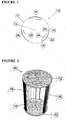
- FIG. 1 and 2 of the accompanying drawings there is shown a wind turbine apparatus 10 comprising a pair of end plate discs 12 (only one of which can be seen in Figure 1 ).
- the end plate discs 12 are mounted on a central axis 14 and are arranged for rotation about the central axis 14.
- the apparatus 10 further comprises a plurality, in this case three, of asymmetrical aero foil turbine blades 16.
- the blades 16 are equispaced about the periphery of the discs 12 and are located between the discs 12.
- Each blade 16 comprises a leading edge 18, a trailing edge 20, an outer low pressure lift producing curved surface 22 and an inner relatively high (ambient) pressure surface 24.
- each blade 16 is cupped by virtue of a hollow 28 between an inner face of the surface 22 thereof and an adjacent face of the corresponding surface 24.
- the blades 16 may be provided with cut away portions adjacent the trailing edges 20.
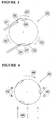
- a twin blade apparatus 30 there is shown a plurality of arrows 31 which indicate wind direction.
- a turbine spinning direction is indicated by arrows 32.
- the turbine blades 16 are conveniently held between the two outer end discs 12 as described hereinabove. However, they can also be curved back into the central axis 14 without end plates.
- the number of blades used in a wind turbine apparatus 10 of the present invention is two or three but more can be utilised if desired.
- each blade 16 provides the wind turbine apparatus 10 with a dual drag and lift operational effect.
- the curved outer surface 22 preferably largely follows an outer curve of the end plate discs 12.
- the inner high pressure surface 24 can extend rearwardly from the leading edge 18 for a distance from 10 - 90% of the distance between the leading edge 18 and the trailing edge 20. However, this distance is preferably about 50 - 60% of the distance from the leading edge 18 to the trailing edge 20 as this has been found to offer a preferred compromise between early start up performance and Tip Speed Ratio (TSR) performance.
- TSR Tip Speed Ratio
- This configuration provides sufficient inside surface for the wind path to be induced to flow smoothly back across the inside of each blade 16 with only a minimal performance change from a full foil.
- the foil cupped shape enables the wind air to be caught even in very light winds so that the wind turbine apparatus 10 can be readily started even in light wind conditions.
- the wind turbine apparatus 10 gains sufficient rotational speed and/or the wind gains sufficient strength, it begins to act as a lift type device and the apparatus 10 is therefore able to spin faster than wind speed. It has been found that the TSR exceeds 1 and may typically operate in the 1.5 - 3 range.
- FIG 4 of the accompanying drawings there is shown a turbine blade apparatus 40 similar to that shown in Figure 1 .
- This embodiment also comprises a pair of opposed wind deflection members 42 and 44.
- the deflection member 42 has a first plate A and a second plate B.
- the deflection member 44 has a first plate D and a second plate C.
- Wind direction is shown by arrows 46 whilst the turbine apparatus 40 spinning direction is shown by an arrow 48.
- FIG 5 of the accompanying drawings there is shown a turbine blade apparatus 50, mounted on a ridge line 52 of a roof 54. Wind direction is shown by arrows 56 and the turbine apparatus 50 spinning direction is shown by an arrow 58.
- the turbine blade apparatus is mounted by means of a support frame 59.
- Addition of the deflection members 42 and 44 about the periphery of the wind turbine apparatus can increase turbine performance.
- the plates A and D clearly provide an extra degree of wind concentration through the turbine apparatus 40.
- the presence of these plates leads to an increase in performance.
- the largest individual improvement from a single plate comes from the plate B which does not compress wind into the turbine.
- plate C does not compress wind but also provides significant improvements.
- the deflection members 42 and 44 alter the wind flow patterns through the turbine to advantageous performance effect.
- the apex edges of the deflector members 42 and 44 are disposed at a distance of less than 20% of the diameter of the wind turbine from the wind turbine to produce significant improvements in performance.
- the roof 54 provides one element of a wind deflector. This provides some of the benefits of the embodiments shown in Figure 4 .
- wind turbine apparatus can be mounted at building edges such as 90° building corners. It has been found that such corners provide an opportunity for mounting of the apparatus of the present invention as the building corners provide an area of wind concentration and offer natural deflector plate type geometry.
- roof top ridge lines and building corners structurally are the most strong positions at which to mount wind turbine apparatuses according to the present invention.
- FIG. 6 there are shown three examples of wind turbine apparatuses mounted on roof ridge lines. At (a) there is shown a single module, at (b) there is shown a double module and at (c) there is shown a triple module.
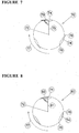
- Figure 7 of the accompanying drawings there is shown an end view of a conventional wind turbine apparatus 70.
- a wind turbine apparatus 70 having a central rotational axis 72 and a plurality of peripheral solid turbine foil blades 74.
- the blades 74 are symmetrical when viewed in end elevation as seen in Figure 7 .
- the blades 74 have a leading end 76 and a trailing edge 78.
- the turbine spinning direction is shown by an arrow 77.
- the blades 74 are disposed at an angle of 90° relative to a radius 75 extending from the axis 72 and intersecting with a line 79 extending from the trailing edge 78 to a mid point where the blade 74 is thickest. As can be seen each trailing edge 78 extends outwardly beyond the confines of the discs 12. It has been found that this 90° angle is detrimental to efficiency of the apparatus 70.
- Figure 8 there is shown a wind turbine apparatus 80 in accordance with the present invention in which solid turbine foil blades 74 are disposed at an angle of less than 90° to a radius 81 extending from the axis 72 intersecting with a line 83 extending from the trailing edge 78 to a mid point where the blade 74 is thickest.
- FIG. 9 of the accompanying drawings there is shown a turbine blade turbine apparatus 90 of the present invention which is similar to that shown in Figure 8 .
- the apparatus 90 comprises a pair of cupped turbine blades 16 similar to those shown in Figure 1 .
- a line from the trailing edge 20 of each blade 16 to the mid point of the thickest part of the blade 16 intersects a radius line 92 at an angle of about 76°.
- FIG. 10 of the accompanying drawings there is shown a single module wind turbine apparatus 100 of the present invention.
- two wind turbine sections 10 are placed together to form one complete module.
- these turbine sections 10 comprise the plate discs 12 and the turbine blades 16 together with the axis 14.
- the two blades 16 of one section are rotated at 90° from the two turbine blades 16 of the other section.
- This arrangement provides a smoother torque curve and generally smoother and better balanced performance than single sections of two blades only.
- FIG 11 of the accompanying drawings there is shown an apparatus 110 similar to that shown in Figure 1 .
- the apparatus 110 comprises turbine foil blades 112 which have flexible trailing edges 114.
- the trailing edges 114 tend to flex outwardly at increased rotational speeds.
- each trailing edge 114 is arranged to move from its relaxed stationary position outwardly as the spin rate increases. In this way, if rotational speeds become excessive the trailing edges 114 flex outwardly and apply a lower lift and higher drag effect to inhibit increased rotational speeds of the apparatus 110.
- the blades 112 could be made flexible other than at the trailing edge to achieve a similar result to that achieved by the use of the flexible trailing edges 114.
- the wind turbine apparatus of the present invention would be made in a modular style so that a number of units could be connected together in a modular arrangement on a building. Further, it is envisaged that the individual turbines would be relatively easy to manufacture cheaply by low cost mass production techniques such as injection moulding and extrusion. Further, the units could be made from plastics materials. Further, although the embodiments described herein utilise units with a horizontal axis of rotation it is envisaged that units with vertical axis of rotation or any angle in between horizontal and vertical could be utilised.
- the wind turbine apparatus of the present invention is particularly envisaged for use in generation of electricity.
- the units of the present invention could utilise regularly available electrical connectors and that the plurality of units in a modular system could be connected together in known manner similar to that employed for photo voltaic solar panels.
- the apparatus of the present invention is designed for mounting onto buildings at external locations of wind concentration, in most instances these locations are also usually sunny. It therefore stands to reason that there could be significant cost savings if the apparatus also incorporated the ability to heat water.
- Incorporated into the apparatus of the present invention is the ability to also heat water by solar means without affecting the electrical generation performance of the turbine. This has the advantage of being able to create hot water for a small cost addition, above the base cost of the turbines themselves. Instead of a consumer having to pay the traditional large cost of a conventional solar hot water system, they can now obtain hot water for smaller cost by incorporating it into their purchase of apparatus of the present invention. This way the consumer can save on their solar hot water system costs in addition to now being able to generate electricity.
- Figure 12(a) is by running water through an axis 14 in the form of a tube and incorporating parabolic micro-strip reflection into the insides of blades.
- the sun's rays 130 can be refracted off the inside of the blades and concentrated onto the axis tube to heat the water. Although some sunlight is blocked by the blades as they spin, this method has the advantage of suiting a wider range of sun angles.
- Another example is by running water through the mounting frame base 59 and heating via conventional solar thermal means as shown in Figure 12(b) at 122.
- Another example is by running water through the mounting frame top and heating via conventional solar thermal means as shown in Figure 12(b) at 124.
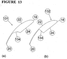
- FIG 13(a) and 13(b) there are shown examples of turbine blades 131 and 132 which have cut away profiles. These blades may be used in place of the blades 16 shown in Figures 1 and 2 . As can be seen these blade embodiments do not have a hollow 28 but they still have the surface 24 which extends partially from the leading edge 18 towards the trailing edge 20. Thus, in each case there is a rearwardly facing surface 134 arranged to catch wind at start up in similar manner to the hollow 28.
Landscapes
- Engineering & Computer Science (AREA)
- Life Sciences & Earth Sciences (AREA)
- Sustainable Development (AREA)
- Sustainable Energy (AREA)
- Chemical & Material Sciences (AREA)
- Combustion & Propulsion (AREA)
- Mechanical Engineering (AREA)
- General Engineering & Computer Science (AREA)
- Wind Motors (AREA)
Applications Claiming Priority (3)
| Application Number | Priority Date | Filing Date | Title |
|---|---|---|---|
| AU2006906751A AU2006906751A0 (en) | 2006-12-04 | Modular wind turbine system | |
| AU2007904481A AU2007904481A0 (en) | 2007-08-21 | Modular wind turbine system | |
| PCT/AU2007/001865 WO2008067593A1 (en) | 2006-12-04 | 2007-12-04 | A wind turbine apparatus |
Publications (3)
| Publication Number | Publication Date |
|---|---|
| EP2102493A1 EP2102493A1 (en) | 2009-09-23 |
| EP2102493A4 EP2102493A4 (en) | 2010-10-20 |
| EP2102493B1 true EP2102493B1 (en) | 2017-05-03 |
Family
ID=39491561
Family Applications (1)
| Application Number | Title | Priority Date | Filing Date |
|---|---|---|---|
| EP07815663.5A Not-in-force EP2102493B1 (en) | 2006-12-04 | 2007-12-04 | A wind turbine apparatus |
Country Status (8)
| Country | Link |
|---|---|
| US (1) | US9303622B2 (enExample) |
| EP (1) | EP2102493B1 (enExample) |
| JP (1) | JP2010511831A (enExample) |
| CN (1) | CN101583792B (enExample) |
| AU (1) | AU2007329173B2 (enExample) |
| CA (1) | CA2671858C (enExample) |
| NZ (1) | NZ578143A (enExample) |
| WO (1) | WO2008067593A1 (enExample) |
Cited By (1)
| Publication number | Priority date | Publication date | Assignee | Title |
|---|---|---|---|---|
| CN110735763A (zh) * | 2019-10-31 | 2020-01-31 | 祁家琦 | 一种垂直轴风力发电机 |
Families Citing this family (17)
| Publication number | Priority date | Publication date | Assignee | Title |
|---|---|---|---|---|
| AU2007329173B2 (en) | 2006-12-04 | 2013-12-19 | Design Licensing International Pty Ltd | A wind turbine apparatus |
| AU2009243924B2 (en) | 2008-05-07 | 2013-11-21 | Design Licensing International Pty Ltd | Wind turbine |
| GB0912695D0 (en) | 2009-07-22 | 2009-08-26 | Power Collective The Ltd | A generator |
| JP2011038468A (ja) * | 2009-08-11 | 2011-02-24 | Global Energy Co Ltd | 発電車両 |
| KR101068443B1 (ko) * | 2009-12-24 | 2011-09-28 | 황지선 | 풍력 발전용 로터 |
| FR2957387B1 (fr) * | 2010-03-09 | 2017-05-12 | Erick Gros-Dubois | Eolienne a rendement eleve |
| WO2012028893A2 (en) * | 2010-08-31 | 2012-03-08 | Matrahazi Janos | Wind turbine |
| BE1019714A3 (nl) * | 2010-12-31 | 2012-10-02 | Dacus Walter | Windturbine met verticale as. |
| US20110232630A1 (en) * | 2011-06-03 | 2011-09-29 | Jason Tsao | Solar collector/wind deflector conversion of a solar and wind converter |
| US9022721B2 (en) | 2011-10-10 | 2015-05-05 | Wind Power Systems, LLC | Vertical axis wind turbine |
| AT512326B1 (de) * | 2011-12-29 | 2013-09-15 | Wind Gmbh T | Strömungsmaschine |
| CN102562442B (zh) * | 2012-02-07 | 2015-09-16 | 秦皇岛风日和科技有限公司 | 垂直轴风力发电机叶片 |
| BE1020677A3 (nl) * | 2012-05-08 | 2014-03-04 | Devisch Geert | Windturbine en gebouw omvattende een dergelijke windturbine. |
| WO2015014370A1 (en) * | 2013-08-02 | 2015-02-05 | Vestas Wind Systems A/S | A blade for a wind turbine and a method for manufacturing a blade for a wind turbine |
| USD766808S1 (en) * | 2014-08-20 | 2016-09-20 | Don Allen Harwood | Wing with slipstream turbine |
| US10487799B2 (en) * | 2015-12-18 | 2019-11-26 | Dan Pendergrass | Pressure and vacuum assisted vertical axis wind turbines |
| JP6302591B1 (ja) * | 2017-06-08 | 2018-03-28 | 豊 根本 | 高層ルーフ向けの風力発電機 |
Citations (1)
| Publication number | Priority date | Publication date | Assignee | Title |
|---|---|---|---|---|
| US1835018A (en) * | 1925-10-09 | 1931-12-08 | Leblanc Vickers Maurice Sa | Turbine having its rotating shaft transverse to the flow of the current |
Family Cites Families (70)
| Publication number | Priority date | Publication date | Assignee | Title |
|---|---|---|---|---|
| US705922A (en) * | 1901-11-13 | 1902-07-29 | Albert Gran | Wind-motor. |
| US1574171A (en) * | 1924-04-02 | 1926-02-23 | James T Ryan | Windmill |
| GB561435A (en) | 1942-12-23 | 1944-05-19 | Charles Owen Griffith | Turbines |
| US3033441A (en) * | 1956-05-08 | 1962-05-08 | Benninger Ag Maschf | Turbomachine |
| US3070287A (en) * | 1959-07-16 | 1962-12-25 | Eck Bruno | Drum rotor for radial blower |
| JPS5390543A (en) * | 1977-01-18 | 1978-08-09 | Jiyuntarou Yamada | Tower type exchanging apparatus of wind and sun shine energy |
| FR2395409A1 (fr) * | 1977-06-20 | 1979-01-19 | Lagarde Jean De | Pale flexible et aerogenerateur a axe vertical comportant de telles pales |
| US4162410A (en) * | 1977-11-30 | 1979-07-24 | Amick James L | Vertical-axis windmill |
| US4247251A (en) * | 1978-05-17 | 1981-01-27 | Wuenscher Hans F | Cycloidal fluid flow engine |
| NL7809790A (nl) * | 1978-09-27 | 1980-03-31 | Mattheus Willem Verplanke | Inrichting voor het opwekken van energie uit een stro- mend medium. |
| US4245958A (en) * | 1978-11-22 | 1981-01-20 | Ewers Marion H | Vertical axis wind turbine |
| JPS55142978A (en) | 1979-04-23 | 1980-11-07 | Ogawa Kenbi:Kk | Vertical shaft wind wheel |
| GB2049066A (en) | 1979-05-09 | 1980-12-17 | Santos Afonso L D | Apparatus for generating energy |
| US4321476A (en) * | 1980-06-24 | 1982-03-23 | Buels Jesse H | Bi-directional wind power generator |
| GB2082260B (en) * | 1980-08-20 | 1984-01-25 | Nianbilla Co Ltd | Vertical axis windmill |
| SE433648B (sv) * | 1981-05-15 | 1984-06-04 | Saab Scania Ab | Varvtalsbegrensande anordning vid en vertikalaxlad vindturbin |
| US4379972A (en) * | 1981-05-26 | 1983-04-12 | Daniel T. Sosa | Turbine ventilator |
| US4430044A (en) * | 1981-11-23 | 1984-02-07 | Liljegren L Kenyon | Vertical axis wind turbine |
| US4486143A (en) * | 1982-09-01 | 1984-12-04 | Mcvey Paul W | Turbine-type wind machine |
| SE8205692D0 (sv) * | 1982-10-06 | 1982-10-06 | Arne F Jonsson | Tvers axeln genomstrommad stromningsmaskin med stellbara skovlar |
| GB8626347D0 (en) * | 1986-11-04 | 1986-12-03 | Bicc Plc | Wind energy convertor |
| US5076759A (en) | 1986-10-29 | 1991-12-31 | Schoenell Juergen | Windmill |
| SU1733680A1 (ru) * | 1990-01-03 | 1992-05-15 | Сумский филиал Харьковского политехнического института им.В.И.Ленина | Лопасть ветроколеса |
| SU1733681A1 (ru) | 1990-04-27 | 1992-05-15 | Научно-Производственное Объединение По Исследованию И Проектированию Энергетического Оборудования Им.И.И.Ползунова | Ветроколесо |
| GR910200234U (en) * | 1990-05-31 | 1992-07-30 | Mihail Valsamidis | Turbine wind machine with a vertical axis |
| US5527151A (en) * | 1992-03-04 | 1996-06-18 | Northern Power Systems, Inc. | Advanced wind turbine with lift-destroying aileron for shutdown |
| RU2044157C1 (ru) * | 1992-07-31 | 1995-09-20 | Лев Анатольевич Степанов | Аэрогидродинамический двигатель |
| RU2096259C1 (ru) * | 1993-11-15 | 1997-11-20 | Владимир Викторович Мозжилкин | Роторный вертикально-осевой ветродвижитель |
| US5451138A (en) * | 1994-01-11 | 1995-09-19 | Northeastern University | Unidirecional reaction turbine operable under reversible fluid from flow |
| US5642984A (en) | 1994-01-11 | 1997-07-01 | Northeastern University | Helical turbine assembly operable under multidirectional fluid flow for power and propulsion systems |
| US5640984A (en) * | 1995-09-12 | 1997-06-24 | Dubunsky; Emanuel | Special fold-up umbrella having rib and frame design for easier opening and closing of umbrella, and two canopies designed to stabilize the ribs and vent the air |
| FR2752599B1 (fr) * | 1996-08-23 | 2002-11-29 | Gual Georges Jean | Module stato-eolien a conformation plate et periptere |
| JPH11107907A (ja) * | 1997-10-04 | 1999-04-20 | Yoshiro Nakamatsu | 対流エネルギ装置 |
| US6097104A (en) * | 1999-01-19 | 2000-08-01 | Russell; Thomas H. | Hybrid energy recovery system |
| JPH11336340A (ja) * | 1998-05-25 | 1999-12-07 | Kumagai Gumi Co Ltd | 給電装置 |
| IL126678A (en) * | 1998-10-20 | 2003-01-12 | Bruce Brill | Modular wind energy device |
| US6884020B2 (en) * | 1999-01-06 | 2005-04-26 | Water Power Industries As | Turbine driven with a fluid medium |
| JP2001193631A (ja) * | 2000-01-11 | 2001-07-17 | Penta Ocean Constr Co Ltd | 風力発電装置 |
| JP2002021705A (ja) * | 2000-07-05 | 2002-01-23 | Koji Iizuka | 屋根設置用風車 |
| US6784566B2 (en) * | 2001-01-25 | 2004-08-31 | Robert Nason Thomas | Coupled vortex vertical axis wind turbine |
| NL1019855C2 (nl) * | 2001-06-13 | 2002-12-16 | Ngup Holding B V | Rotor, windturbine en samenstel daarvan. |
| US6877948B2 (en) * | 2001-07-10 | 2005-04-12 | Alan B. Cutcher | Wind turbine generator |
| US6538340B2 (en) | 2001-08-06 | 2003-03-25 | Headwinds Corporation | Wind turbine system |
| JP2003065206A (ja) * | 2001-08-24 | 2003-03-05 | Daiwa House Ind Co Ltd | 風車設置建物構造 |
| JP3368537B1 (ja) * | 2001-11-08 | 2003-01-20 | 学校法人東海大学 | 直線翼型風水車 |
| US6638005B2 (en) * | 2002-01-17 | 2003-10-28 | John W. Holter | Coaxial wind turbine apparatus having a closeable air inlet opening |
| US6870280B2 (en) * | 2002-05-08 | 2005-03-22 | Elcho R. Pechler | Vertical-axis wind turbine |
| JP2004019537A (ja) * | 2002-06-17 | 2004-01-22 | Ko Yamaguchi | クリーンエネルギー発電機 |
| US6740989B2 (en) * | 2002-08-21 | 2004-05-25 | Pacifex Management Inc. | Vertical axis wind turbine |
| JP3451085B1 (ja) * | 2002-09-20 | 2003-09-29 | 常夫 野口 | 風力発電用の風車 |
| JP2004176551A (ja) * | 2002-11-25 | 2004-06-24 | Satsuki Seisakusho:Kk | ダリウス形風車 |
| US6814070B2 (en) * | 2003-01-06 | 2004-11-09 | Davis Energy Group, Inc. | Molded polymer solar water heater |
| JP2005036649A (ja) * | 2003-04-23 | 2005-02-10 | Shinko Electric Co Ltd | 垂直軸型風力発電装置 |
| US6966747B2 (en) * | 2003-04-30 | 2005-11-22 | Taylor Ronald J | Wind turbine having airfoils for blocking and directing wind and rotors with or without a central gap |
| DE10328249A1 (de) * | 2003-06-24 | 2005-02-03 | Roland Reinhard | Windrotor Windkraftmaschine |
| GB2404700A (en) * | 2003-08-01 | 2005-02-09 | Robin Matthew Hilder | Roof mounted wind turbine |
| RU2249125C1 (ru) * | 2003-09-24 | 2005-03-27 | Царев Виктор Владимирович | Система автономного электро- и теплоснабжения жилых и производственных помещений |
| JP2005220893A (ja) * | 2004-02-03 | 2005-08-18 | Dmw Japan:Kk | 全方向型垂直型風車に取り付ける風向蛇付風増速装置 |
| US7008171B1 (en) * | 2004-03-17 | 2006-03-07 | Circle Wind Corp. | Modified Savonius rotor |
| KR100571123B1 (ko) * | 2004-03-19 | 2006-04-14 | 주장식 | 태양열을 이용한 온수가열이 가능한 풍력발전기 |
| US7109599B2 (en) * | 2004-05-05 | 2006-09-19 | Watkins Philip G | Omni-directional wind turbine electric generation system |
| WO2005116446A1 (ja) * | 2004-05-27 | 2005-12-08 | Intellectual Property Bank Corp. | 垂直軸風車用ブレードおよび垂直軸風車 |
| ITCE20050006A1 (it) * | 2005-03-11 | 2006-09-12 | Mast S R L B | Turbina eolica con rotore a portanza alare e convogliatore |
| FR2886353A1 (fr) | 2005-05-27 | 2006-12-01 | Michel Georges Ponge | Turbine aeromotrice avec accelerateur de flux |
| WO2007027113A1 (en) | 2005-09-02 | 2007-03-08 | Ballena Abraham E | Vertical axis wind turbine |
| GB2431696B (en) * | 2005-10-28 | 2007-10-03 | Adrian Raphael Montford | Roof Turbine |
| GB0612677D0 (en) * | 2006-06-27 | 2006-08-09 | Taylor Derek A | Energy conversion device for wind & other fluids |
| AU2007329173B2 (en) | 2006-12-04 | 2013-12-19 | Design Licensing International Pty Ltd | A wind turbine apparatus |
| AU2009243924B2 (en) | 2008-05-07 | 2013-11-21 | Design Licensing International Pty Ltd | Wind turbine |
| EP2425128B1 (en) * | 2009-04-28 | 2018-12-19 | Bang-Moeller, Soeren | Combined wing and turbine device for improved utilization of fluid flow energy |
-
2007
- 2007-12-04 AU AU2007329173A patent/AU2007329173B2/en not_active Ceased
- 2007-12-04 CN CN2007800498941A patent/CN101583792B/zh not_active Expired - Fee Related
- 2007-12-04 NZ NZ578143A patent/NZ578143A/xx not_active IP Right Cessation
- 2007-12-04 WO PCT/AU2007/001865 patent/WO2008067593A1/en not_active Ceased
- 2007-12-04 CA CA2671858A patent/CA2671858C/en not_active Expired - Fee Related
- 2007-12-04 EP EP07815663.5A patent/EP2102493B1/en not_active Not-in-force
- 2007-12-04 JP JP2009539570A patent/JP2010511831A/ja active Pending
-
2009
- 2009-06-04 US US12/478,597 patent/US9303622B2/en not_active Expired - Fee Related
Patent Citations (1)
| Publication number | Priority date | Publication date | Assignee | Title |
|---|---|---|---|---|
| US1835018A (en) * | 1925-10-09 | 1931-12-08 | Leblanc Vickers Maurice Sa | Turbine having its rotating shaft transverse to the flow of the current |
Cited By (1)
| Publication number | Priority date | Publication date | Assignee | Title |
|---|---|---|---|---|
| CN110735763A (zh) * | 2019-10-31 | 2020-01-31 | 祁家琦 | 一种垂直轴风力发电机 |
Also Published As
| Publication number | Publication date |
|---|---|
| AU2007329173A1 (en) | 2008-06-12 |
| CN101583792A (zh) | 2009-11-18 |
| EP2102493A4 (en) | 2010-10-20 |
| NZ578143A (en) | 2013-01-25 |
| CA2671858C (en) | 2015-09-29 |
| HK1137206A1 (en) | 2010-07-23 |
| US9303622B2 (en) | 2016-04-05 |
| WO2008067593A1 (en) | 2008-06-12 |
| AU2007329173B2 (en) | 2013-12-19 |
| CN101583792B (zh) | 2013-02-13 |
| EP2102493A1 (en) | 2009-09-23 |
| JP2010511831A (ja) | 2010-04-15 |
| CA2671858A1 (en) | 2008-06-12 |
| US20090304512A1 (en) | 2009-12-10 |
Similar Documents
| Publication | Publication Date | Title |
|---|---|---|
| EP2102493B1 (en) | A wind turbine apparatus | |
| US7008171B1 (en) | Modified Savonius rotor | |
| US7976267B2 (en) | Helix turbine system and energy production means | |
| US8226369B2 (en) | Conical helicoid wind turbine | |
| US10495063B2 (en) | Wind turbine | |
| US20130017084A1 (en) | High efficiency verical axis wind turbine | |
| AU2006257538A1 (en) | A blade with hinged blade tip | |
| US20200300217A1 (en) | Vertical axis wind turbine | |
| US20090256359A1 (en) | Wind turbine and wind power installation | |
| GB2451670A (en) | A fluid driven rotor | |
| CN109931215B (zh) | 一种具有永磁限位功能的帆翼式垂直轴风轮机 | |
| BRPI0901809A2 (pt) | pás de turbina eólica com ponteiras retorcidas e cÈnicas | |
| WO2017144837A1 (en) | Wind turbine system, method and application | |
| JP2013521431A (ja) | 垂直シャフトを備える風力ローター | |
| CN201165936Y (zh) | 一臂多叶垂直轴风力机 | |
| KR101263935B1 (ko) | 터빈 블레이드 및 이를 구비한 풍력 발전기 | |
| CN106050556A (zh) | 垂直轴风力机自适应柔性叶片 | |
| WO2021017033A1 (zh) | 一种摆动叶片式导流型垂直轴风轮机 | |
| CN101949362B (zh) | 一种垂直轴风力机 | |
| CN200985865Y (zh) | 垂直轴风力发电装置 | |
| CN216894723U (zh) | 一种风轮结构 | |
| CN2471963Y (zh) | 塔轴式摆翼风力机 | |
| HK1137206B (en) | A wind turbine apparatus | |
| CN1015732B (zh) | 风力涡轮机 | |
| CN2802117Y (zh) | 立轴式风车装置 |
Legal Events
| Date | Code | Title | Description |
|---|---|---|---|
| PUAI | Public reference made under article 153(3) epc to a published international application that has entered the european phase |
Free format text: ORIGINAL CODE: 0009012 |
|
| 17P | Request for examination filed |
Effective date: 20090702 |
|
| AK | Designated contracting states |
Kind code of ref document: A1 Designated state(s): AT BE BG CH CY CZ DE DK EE ES FI FR GB GR HU IE IS IT LI LT LU LV MC MT NL PL PT RO SE SI SK TR |
|
| DAX | Request for extension of the european patent (deleted) | ||
| A4 | Supplementary search report drawn up and despatched |
Effective date: 20100922 |
|
| 17Q | First examination report despatched |
Effective date: 20120201 |
|
| REG | Reference to a national code |
Ref country code: DE Ref legal event code: R079 Ref document number: 602007050866 Country of ref document: DE Free format text: PREVIOUS MAIN CLASS: F03D0003020000 Ipc: F03D0003000000 |
|
| GRAP | Despatch of communication of intention to grant a patent |
Free format text: ORIGINAL CODE: EPIDOSNIGR1 |
|
| RIC1 | Information provided on ipc code assigned before grant |
Ipc: F03D 3/00 20060101AFI20161017BHEP Ipc: F03D 3/04 20060101ALI20161017BHEP |
|
| INTG | Intention to grant announced |
Effective date: 20161118 |
|
| GRAS | Grant fee paid |
Free format text: ORIGINAL CODE: EPIDOSNIGR3 |
|
| GRAA | (expected) grant |
Free format text: ORIGINAL CODE: 0009210 |
|
| AK | Designated contracting states |
Kind code of ref document: B1 Designated state(s): AT BE BG CH CY CZ DE DK EE ES FI FR GB GR HU IE IS IT LI LT LU LV MC MT NL PL PT RO SE SI SK TR |
|
| REG | Reference to a national code |
Ref country code: GB Ref legal event code: FG4D |
|
| REG | Reference to a national code |
Ref country code: AT Ref legal event code: REF Ref document number: 890298 Country of ref document: AT Kind code of ref document: T Effective date: 20170515 Ref country code: CH Ref legal event code: EP |
|
| REG | Reference to a national code |
Ref country code: IE Ref legal event code: FG4D |
|
| REG | Reference to a national code |
Ref country code: DE Ref legal event code: R096 Ref document number: 602007050866 Country of ref document: DE |
|
| REG | Reference to a national code |
Ref country code: NL Ref legal event code: MP Effective date: 20170503 |
|
| REG | Reference to a national code |
Ref country code: AT Ref legal event code: MK05 Ref document number: 890298 Country of ref document: AT Kind code of ref document: T Effective date: 20170503 |
|
| REG | Reference to a national code |
Ref country code: LT Ref legal event code: MG4D |
|
| PG25 | Lapsed in a contracting state [announced via postgrant information from national office to epo] |
Ref country code: FI Free format text: LAPSE BECAUSE OF FAILURE TO SUBMIT A TRANSLATION OF THE DESCRIPTION OR TO PAY THE FEE WITHIN THE PRESCRIBED TIME-LIMIT Effective date: 20170503 Ref country code: GR Free format text: LAPSE BECAUSE OF FAILURE TO SUBMIT A TRANSLATION OF THE DESCRIPTION OR TO PAY THE FEE WITHIN THE PRESCRIBED TIME-LIMIT Effective date: 20170804 Ref country code: LT Free format text: LAPSE BECAUSE OF FAILURE TO SUBMIT A TRANSLATION OF THE DESCRIPTION OR TO PAY THE FEE WITHIN THE PRESCRIBED TIME-LIMIT Effective date: 20170503 Ref country code: ES Free format text: LAPSE BECAUSE OF FAILURE TO SUBMIT A TRANSLATION OF THE DESCRIPTION OR TO PAY THE FEE WITHIN THE PRESCRIBED TIME-LIMIT Effective date: 20170503 Ref country code: AT Free format text: LAPSE BECAUSE OF FAILURE TO SUBMIT A TRANSLATION OF THE DESCRIPTION OR TO PAY THE FEE WITHIN THE PRESCRIBED TIME-LIMIT Effective date: 20170503 |
|
| PG25 | Lapsed in a contracting state [announced via postgrant information from national office to epo] |
Ref country code: PL Free format text: LAPSE BECAUSE OF FAILURE TO SUBMIT A TRANSLATION OF THE DESCRIPTION OR TO PAY THE FEE WITHIN THE PRESCRIBED TIME-LIMIT Effective date: 20170503 Ref country code: IS Free format text: LAPSE BECAUSE OF FAILURE TO SUBMIT A TRANSLATION OF THE DESCRIPTION OR TO PAY THE FEE WITHIN THE PRESCRIBED TIME-LIMIT Effective date: 20170903 Ref country code: BG Free format text: LAPSE BECAUSE OF FAILURE TO SUBMIT A TRANSLATION OF THE DESCRIPTION OR TO PAY THE FEE WITHIN THE PRESCRIBED TIME-LIMIT Effective date: 20170803 Ref country code: NL Free format text: LAPSE BECAUSE OF FAILURE TO SUBMIT A TRANSLATION OF THE DESCRIPTION OR TO PAY THE FEE WITHIN THE PRESCRIBED TIME-LIMIT Effective date: 20170503 Ref country code: SE Free format text: LAPSE BECAUSE OF FAILURE TO SUBMIT A TRANSLATION OF THE DESCRIPTION OR TO PAY THE FEE WITHIN THE PRESCRIBED TIME-LIMIT Effective date: 20170503 Ref country code: LV Free format text: LAPSE BECAUSE OF FAILURE TO SUBMIT A TRANSLATION OF THE DESCRIPTION OR TO PAY THE FEE WITHIN THE PRESCRIBED TIME-LIMIT Effective date: 20170503 |
|
| PG25 | Lapsed in a contracting state [announced via postgrant information from national office to epo] |
Ref country code: RO Free format text: LAPSE BECAUSE OF FAILURE TO SUBMIT A TRANSLATION OF THE DESCRIPTION OR TO PAY THE FEE WITHIN THE PRESCRIBED TIME-LIMIT Effective date: 20170503 Ref country code: SK Free format text: LAPSE BECAUSE OF FAILURE TO SUBMIT A TRANSLATION OF THE DESCRIPTION OR TO PAY THE FEE WITHIN THE PRESCRIBED TIME-LIMIT Effective date: 20170503 Ref country code: EE Free format text: LAPSE BECAUSE OF FAILURE TO SUBMIT A TRANSLATION OF THE DESCRIPTION OR TO PAY THE FEE WITHIN THE PRESCRIBED TIME-LIMIT Effective date: 20170503 Ref country code: CZ Free format text: LAPSE BECAUSE OF FAILURE TO SUBMIT A TRANSLATION OF THE DESCRIPTION OR TO PAY THE FEE WITHIN THE PRESCRIBED TIME-LIMIT Effective date: 20170503 Ref country code: DK Free format text: LAPSE BECAUSE OF FAILURE TO SUBMIT A TRANSLATION OF THE DESCRIPTION OR TO PAY THE FEE WITHIN THE PRESCRIBED TIME-LIMIT Effective date: 20170503 |
|
| REG | Reference to a national code |
Ref country code: DE Ref legal event code: R097 Ref document number: 602007050866 Country of ref document: DE |
|
| PG25 | Lapsed in a contracting state [announced via postgrant information from national office to epo] |
Ref country code: IT Free format text: LAPSE BECAUSE OF FAILURE TO SUBMIT A TRANSLATION OF THE DESCRIPTION OR TO PAY THE FEE WITHIN THE PRESCRIBED TIME-LIMIT Effective date: 20170503 |
|
| PLBE | No opposition filed within time limit |
Free format text: ORIGINAL CODE: 0009261 |
|
| STAA | Information on the status of an ep patent application or granted ep patent |
Free format text: STATUS: NO OPPOSITION FILED WITHIN TIME LIMIT |
|
| 26N | No opposition filed |
Effective date: 20180206 |
|
| PG25 | Lapsed in a contracting state [announced via postgrant information from national office to epo] |
Ref country code: SI Free format text: LAPSE BECAUSE OF FAILURE TO SUBMIT A TRANSLATION OF THE DESCRIPTION OR TO PAY THE FEE WITHIN THE PRESCRIBED TIME-LIMIT Effective date: 20170503 |
|
| REG | Reference to a national code |
Ref country code: DE Ref legal event code: R119 Ref document number: 602007050866 Country of ref document: DE |
|
| REG | Reference to a national code |
Ref country code: CH Ref legal event code: PL |
|
| GBPC | Gb: european patent ceased through non-payment of renewal fee |
Effective date: 20171204 |
|
| REG | Reference to a national code |
Ref country code: IE Ref legal event code: MM4A |
|
| PG25 | Lapsed in a contracting state [announced via postgrant information from national office to epo] |
Ref country code: LU Free format text: LAPSE BECAUSE OF NON-PAYMENT OF DUE FEES Effective date: 20171204 Ref country code: MT Free format text: LAPSE BECAUSE OF NON-PAYMENT OF DUE FEES Effective date: 20171204 |
|
| REG | Reference to a national code |
Ref country code: FR Ref legal event code: ST Effective date: 20180831 |
|
| REG | Reference to a national code |
Ref country code: BE Ref legal event code: MM Effective date: 20171231 |
|
| PG25 | Lapsed in a contracting state [announced via postgrant information from national office to epo] |
Ref country code: IE Free format text: LAPSE BECAUSE OF NON-PAYMENT OF DUE FEES Effective date: 20171204 Ref country code: DE Free format text: LAPSE BECAUSE OF NON-PAYMENT OF DUE FEES Effective date: 20180703 Ref country code: FR Free format text: LAPSE BECAUSE OF NON-PAYMENT OF DUE FEES Effective date: 20180102 |
|
| PG25 | Lapsed in a contracting state [announced via postgrant information from national office to epo] |
Ref country code: BE Free format text: LAPSE BECAUSE OF NON-PAYMENT OF DUE FEES Effective date: 20171231 Ref country code: GB Free format text: LAPSE BECAUSE OF NON-PAYMENT OF DUE FEES Effective date: 20171204 Ref country code: LI Free format text: LAPSE BECAUSE OF NON-PAYMENT OF DUE FEES Effective date: 20171231 Ref country code: CH Free format text: LAPSE BECAUSE OF NON-PAYMENT OF DUE FEES Effective date: 20171231 |
|
| PG25 | Lapsed in a contracting state [announced via postgrant information from national office to epo] |
Ref country code: HU Free format text: LAPSE BECAUSE OF FAILURE TO SUBMIT A TRANSLATION OF THE DESCRIPTION OR TO PAY THE FEE WITHIN THE PRESCRIBED TIME-LIMIT; INVALID AB INITIO Effective date: 20071204 Ref country code: MC Free format text: LAPSE BECAUSE OF FAILURE TO SUBMIT A TRANSLATION OF THE DESCRIPTION OR TO PAY THE FEE WITHIN THE PRESCRIBED TIME-LIMIT Effective date: 20170503 |
|
| PG25 | Lapsed in a contracting state [announced via postgrant information from national office to epo] |
Ref country code: CY Free format text: LAPSE BECAUSE OF NON-PAYMENT OF DUE FEES Effective date: 20170503 |
|
| PG25 | Lapsed in a contracting state [announced via postgrant information from national office to epo] |
Ref country code: TR Free format text: LAPSE BECAUSE OF FAILURE TO SUBMIT A TRANSLATION OF THE DESCRIPTION OR TO PAY THE FEE WITHIN THE PRESCRIBED TIME-LIMIT Effective date: 20170503 |
|
| PG25 | Lapsed in a contracting state [announced via postgrant information from national office to epo] |
Ref country code: PT Free format text: LAPSE BECAUSE OF FAILURE TO SUBMIT A TRANSLATION OF THE DESCRIPTION OR TO PAY THE FEE WITHIN THE PRESCRIBED TIME-LIMIT Effective date: 20170503 |