EP2102074B1 - Protective box for transporting or storing a part in the form of a plate pierced by an opening - Google Patents
Protective box for transporting or storing a part in the form of a plate pierced by an opening Download PDFInfo
- Publication number
- EP2102074B1 EP2102074B1 EP07847843A EP07847843A EP2102074B1 EP 2102074 B1 EP2102074 B1 EP 2102074B1 EP 07847843 A EP07847843 A EP 07847843A EP 07847843 A EP07847843 A EP 07847843A EP 2102074 B1 EP2102074 B1 EP 2102074B1
- Authority
- EP
- European Patent Office
- Prior art keywords
- flange
- stake
- cover
- plate
- shaped part
- Prior art date
- Legal status (The legal status is an assumption and is not a legal conclusion. Google has not performed a legal analysis and makes no representation as to the accuracy of the status listed.)
- Active
Links
- 230000001681 protective effect Effects 0.000 title claims abstract description 7
- 230000003100 immobilizing effect Effects 0.000 abstract description 2
- 239000004809 Teflon Substances 0.000 description 2
- 229920006362 Teflon® Polymers 0.000 description 2
- 239000000463 material Substances 0.000 description 2
- 230000000717 retained effect Effects 0.000 description 2
- 239000000969 carrier Substances 0.000 description 1
- 239000000470 constituent Substances 0.000 description 1
- 230000000694 effects Effects 0.000 description 1
- 239000013013 elastic material Substances 0.000 description 1
- 238000000605 extraction Methods 0.000 description 1
- 239000011121 hardwood Substances 0.000 description 1
- 238000003780 insertion Methods 0.000 description 1
- 230000037431 insertion Effects 0.000 description 1
- 238000004519 manufacturing process Methods 0.000 description 1
- 238000000034 method Methods 0.000 description 1
- 238000012986 modification Methods 0.000 description 1
- 230000004048 modification Effects 0.000 description 1
- 238000004806 packaging method and process Methods 0.000 description 1
- 230000035939 shock Effects 0.000 description 1
- 239000000725 suspension Substances 0.000 description 1
Images


Classifications
-
- B—PERFORMING OPERATIONS; TRANSPORTING
- B65—CONVEYING; PACKING; STORING; HANDLING THIN OR FILAMENTARY MATERIAL
- B65D—CONTAINERS FOR STORAGE OR TRANSPORT OF ARTICLES OR MATERIALS, e.g. BAGS, BARRELS, BOTTLES, BOXES, CANS, CARTONS, CRATES, DRUMS, JARS, TANKS, HOPPERS, FORWARDING CONTAINERS; ACCESSORIES, CLOSURES, OR FITTINGS THEREFOR; PACKAGING ELEMENTS; PACKAGES
- B65D81/00—Containers, packaging elements, or packages, for contents presenting particular transport or storage problems, or adapted to be used for non-packaging purposes after removal of contents
- B65D81/02—Containers, packaging elements, or packages, for contents presenting particular transport or storage problems, or adapted to be used for non-packaging purposes after removal of contents specially adapted to protect contents from mechanical damage
-
- B—PERFORMING OPERATIONS; TRANSPORTING
- B65—CONVEYING; PACKING; STORING; HANDLING THIN OR FILAMENTARY MATERIAL
- B65D—CONTAINERS FOR STORAGE OR TRANSPORT OF ARTICLES OR MATERIALS, e.g. BAGS, BARRELS, BOTTLES, BOXES, CANS, CARTONS, CRATES, DRUMS, JARS, TANKS, HOPPERS, FORWARDING CONTAINERS; ACCESSORIES, CLOSURES, OR FITTINGS THEREFOR; PACKAGING ELEMENTS; PACKAGES
- B65D25/00—Details of other kinds or types of rigid or semi-rigid containers
- B65D25/02—Internal fittings
- B65D25/10—Devices to locate articles in containers
- B65D25/101—Springs, elastic lips, or other resilient elements to locate the articles by pressure
-
- B—PERFORMING OPERATIONS; TRANSPORTING
- B65—CONVEYING; PACKING; STORING; HANDLING THIN OR FILAMENTARY MATERIAL
- B65D—CONTAINERS FOR STORAGE OR TRANSPORT OF ARTICLES OR MATERIALS, e.g. BAGS, BARRELS, BOTTLES, BOXES, CANS, CARTONS, CRATES, DRUMS, JARS, TANKS, HOPPERS, FORWARDING CONTAINERS; ACCESSORIES, CLOSURES, OR FITTINGS THEREFOR; PACKAGING ELEMENTS; PACKAGES
- B65D85/00—Containers, packaging elements or packages, specially adapted for particular articles or materials
- B65D85/30—Containers, packaging elements or packages, specially adapted for particular articles or materials for articles particularly sensitive to damage by shock or pressure
- B65D85/38—Containers, packaging elements or packages, specially adapted for particular articles or materials for articles particularly sensitive to damage by shock or pressure for delicate optical, measuring, calculating or control apparatus
- B65D85/40—Containers, packaging elements or packages, specially adapted for particular articles or materials for articles particularly sensitive to damage by shock or pressure for delicate optical, measuring, calculating or control apparatus for watches or clocks; for components thereof
-
- G—PHYSICS
- G04—HOROLOGY
- G04D—APPARATUS OR TOOLS SPECIALLY DESIGNED FOR MAKING OR MAINTAINING CLOCKS OR WATCHES
- G04D1/00—Gripping, holding, or supporting devices
- G04D1/06—Supporting devices for clockworks or parts of time-pieces
- G04D1/066—Packaging and boxes for transport
Definitions
- Another object of the present invention is to provide a box that can accommodate the widest possible range of pieces of different dimensions (diameter, thickness, diameter of the opening, etc.).
- Another object of the present invention is to provide a box whose unit cost is reduced.
- the cleat is fixedly mounted on the flange, and the flange is itself retained by resilient means provided to recall it towards the cover.
- exerted by the projection on the cleat is always equal to the restoring force provided by the elastic means.
- An advantage of the present invention is therefore that the presence of elastic means makes it possible not to damage the cleat.
- the elastic means must return the flange towards the cover with sufficient force to hold the cleat wedged in the opening of the plate-shaped part. That is to say that, to maintain the cleat wedged in the opening of the plate, it is necessary that it offers less resistance to deformation than the elastic means. Otherwise, the diameter of the cleat remains insufficient to immobilize the room.
- the present invention further provides a box capable of receiving plate-shaped parts that differ in the diameter of their opening.
- the cleat comprises a longitudinally split tubular element, the slotted wall of the tubular element constituting at least two elastic arms.
- the projection formed under the cover is intended to be introduced into the split tubular element in the manner of a wedge, to separate said elastic arms.
- the flange is perforated.
- This feature has the particular advantage of allowing to condition dials already equipped with dial feet.
- this combination has the advantage of allowing the identification of a reference or a bar code possibly carried by the underside of the plate or dial. Thus, it is not necessary to open the box to learn about its contents.
- the box bears a distinctive sign indicating the diameter of the cleat it contains.
- the operation of the box will now be described in reference to figures 2 and 3 .
- the box is first laid flat, and the lid 3 is removed.
- a dial 11 can then be inserted into the box and positioned flat on the flange 6, with the cleat extending through the center hole of the dial.
- the box can then be closed again.
- the cleat 7 can no longer be deformed. It is therefore the mobile flange 6 which lowers under the pressure of the lid 3 by compressing the springs 9a, 9b, 9c and 9d, until the box is completely closed. At this moment, the cylindrical flanges 4 and 5 are completely nested.
- the cylindrical flange 4, within which the flange 6 moves has a small inner shoulder 16 which is provided to limit the stroke of the flange 6 upwards.
- the presence of the shoulder 16 prevents the flange 6 from disengaging the cylindrical flange 4 when the box is open.
- the shoulder 16 ensures that the top of the dial 11 can not come into contact with the underside of the lid 3.
- housings 10a, 10b, 10c and 10d each intended to receive the upper end of one of the helical springs 9a, 9b, 9c and 9d, are further arranged in the lower part of the flange 6.
- the rim 4 has two chamfers 13 intended to facilitate the correct orientation of the flange 6 relative to the bottom 2.
- the presence of the chamfers 13 also facilitates the introduction flask.
- the hunting itself is preferably done with a driving tool having a large bearing surface, so that the flange 6 downwards parallel to the bottom 2.
- the flange 6 has in the center of its upper face a housing constituted by a cylindrical recess 15 provided to receive the cleat 7.
- the inner diameter of the recess 15 corresponds to the outer diameter of the base 14, so that the cleat can be driven up to At the bottom of the recess and to be maintained therein.
- the insertion of the batten into the recess is preferably carried out with a tool designed so as to avoid damaging the clamp of the cleat.
- This tool may for example have the shape of a tube surrounding the cylindrical element of the cleat and bearing against the base 14.
- the flange and flange are made in one piece, so as to reduce production costs. Under these conditions, for example, a box according to the invention can be adapted to another dial dimension simply by changing the flange. It may also be provided in other embodiments to make the cleat not on the flange but on the cover, in this case the cone cooperating with the cleat will be arranged on the flange.
- box according to the invention for packaging other plate-shaped parts than watch dials.
Abstract
Description
La présente invention concerne une boîte protectrice pour le transport ou le stockage d'une pièce ayant la forme d'une pièce plane, ou plaque, percée d'une ouverture ; par exemple un cadran de montre. La présente invention concerne plus particulièrement une telle boîte comportant un dispositif de serrage prévu pour s'étendre dans l'ouverture de la plaque de façon à retenir la plaque. La présente invention concerne notamment une telle boîte prévue pour contenir un cadran de montre.The present invention relates to a protective box for transporting or storing a workpiece in the form of a flat part, or plate, pierced with an opening; for example a watch dial. The present invention relates more particularly to such a box comprising a clamping device intended to extend into the opening of the plate so as to retain the plate. The present invention relates in particular to such a box designed to contain a watch face.
Un but de la présente invention est de fournir une boîte dont la conception minimise les conséquences néfastes que pourrait avoir une manipulation maladroite ou erronée. En particulier, un but est de fournir une boîte conçue pour que la force avec laquelle on presse sur le couvercle n'influence pas la force de maintien de la pièce en forme de plaque.An object of the present invention is to provide a box whose design minimizes the harmful consequences that could have an awkward or wrong handling. In particular, an object is to provide a box designed so that the force with which one presses on the lid does not influence the holding force of the plate-shaped part.
Un autre but est de fournir une boîte prévue pour supporter des chocs accidentels de 5000 g (chute de un mètre sur du bois dur) sans pour autant que le contenu ou la boîte ne subisse quoi que ce soit comme dégâts.Another goal is to provide a box designed to withstand accidental shocks of 5000 g (falling one meter on hardwood) without the content or the box experiencing anything as damage.
Un autre but de la présente invention est de fournir une boîte pouvant accomoder la gamme la plus large possible de pièces de dimensions différentes (diamètre, épaisseur, diamètre de l'ouverture, etc).Another object of the present invention is to provide a box that can accommodate the widest possible range of pieces of different dimensions (diameter, thickness, diameter of the opening, etc.).
Un autre but de la présente invention est de fournir une gamme de boîtes ne se distinguant les unes des autres que par les dimensions du dispositif de serrage qui peut être adapté aux dimensions particulières d'un modèle de pièces.Another object of the present invention is to provide a range of boxes distinguished from each other only by the dimensions of the clamping device which can be adapted to the particular dimensions of a model parts.
Un autre but de la présente invention est de fournir une boite avec laquelle l'introduction et l'extraction d'une pièce est aisée.Another object of the present invention is to provide a box with which the introduction and extraction of a part is easy.
Un autre but de la présente invention est de fournir une boîte dont le coût unitaire est réduit.Another object of the present invention is to provide a box whose unit cost is reduced.
La présente invention atteint ces buts en fournissant une boîte, pour le transport et le stockage d'une pièce ayant la forme d'une plaque percée d'une ouverture, conforme à la revendication 1 annexée.The present invention achieves these objects by providing a box for transporting and storing a workpiece in the form of a plate pierced with an opening according to the appended
Le document
Selon la présente invention, le tasseau est monté fixe sur la flasque, et la flasque est elle-même retenue par des moyens élastiques prévus pour la rappeler en direction du couvercle. Dans ces conditions, lorsque la boîte est fermée, !a force exercée par la saillie sur le tasseau est toujours égale à la force de rappel fournie par les moyens elastiques. Ainsi, la force avec laquelle on presse sur le couvercle n'influence pas la force exercée sur le tasseau. Un avantantge de la présente invention est donc que la présence des moyens élastiques permet de ne pas endommager le tasseau.According to the present invention, the cleat is fixedly mounted on the flange, and the flange is itself retained by resilient means provided to recall it towards the cover. Under these conditions, when the box is closed,! exerted by the projection on the cleat is always equal to the restoring force provided by the elastic means. Thus, the force with which one presses on the lid does not influence the force exerted on the cleat. An advantage of the present invention is therefore that the presence of elastic means makes it possible not to damage the cleat.
Un autre avantage de la présente invention est d'éviter que, sous l'effet d'une trop forte pression, le tasseau n'endommage le cadran.Another advantage of the present invention is to avoid that, under the effect of too much pressure, the cleat does not damage the dial.
Un autre avantage de la présente invention est que seul la flasque et le tasseau entrent en contact avec le cadran. Les parties fonctionnelles du cadran, qui sont situées sur sa face supérieure, n'ont donc jamais à entrer en contact avec les différentes parties de la boîte.Another advantage of the present invention is that only the flange and the cleat come into contact with the dial. The functional parts of the dial, which are located on its upper face, therefore never have to come into contact with the different parts of the box.
Un autre avantage est que la flasque retenue élastiquement permet d'utiliser la même boîte avec des cadrans ayant des épaisseurs différentes.Another advantage is that the elastically retained flange allows the same box to be used with dials having different thicknesses.
Selon la présente invention, les moyens élastiques doivent rappeler la flasque en direction du couvercle avec suffisamment de force pour maintenir le tasseau calé dans l'ouverture de la pièce en forme de plaque. Cela revient à dire que, pour maintenir le tasseau calé dans l'ouverture de la plaque, il est nécessaire que celui-ci offre moins de résistance à la déformation que les moyens élastiques. Sans quoi, le diamètre du tasseau demeure insuffisant pour immobiliser la pièce.According to the present invention, the elastic means must return the flange towards the cover with sufficient force to hold the cleat wedged in the opening of the plate-shaped part. That is to say that, to maintain the cleat wedged in the opening of the plate, it is necessary that it offers less resistance to deformation than the elastic means. Otherwise, the diameter of the cleat remains insufficient to immobilize the room.
Grâce à l'utilisation d'un tasseau déformable élastiquement, la présente invention permet en outre de fournir une boîte pouvant recevoir des pièces en forme de plaque qui diffèrent quant au diamètre de leur ouverture.Through the use of an elastically deformable cleat, the present invention further provides a box capable of receiving plate-shaped parts that differ in the diameter of their opening.
Selon une variante avantageuse de la présente invention, le tasseau comporte un élément tubulaire fendu longitudinalement, la parois fendue de l'élément tubulaire constituant au moins deux bras élastiques. De plus, lors de la fermeture de la boîte, la saillie formée sous le couvercle est prévue pour s'introduire dans l'élément tubulaire fendu, à la manière d'un coin, pour écarter lesdits bras élastiques.According to an advantageous variant of the present invention, the cleat comprises a longitudinally split tubular element, the slotted wall of the tubular element constituting at least two elastic arms. In addition, when closing the box, the projection formed under the cover is intended to be introduced into the split tubular element in the manner of a wedge, to separate said elastic arms.
Selon encore une autre variante avantageuse de la présente invention, la flasque est ajourée. Cette caractéristique présente notamment l'avantage de permettre de conditionner des cadrans déjà munis de pied de cadran. D'autre part, si la caractéristique d'une flasque ajourée est combinée avec celle d'un fond transparent ou translucide, cette combinaison présente l'avantage de permettre l'indentification d'une référence ou d'un code barre éventuellement porté par la face inférieure de la plaque ou du cadran. Ainsi, il n'est pas nécessaire d'ouvrir la boîte pour prendre connaissance de son contenu.According to yet another advantageous variant of the present invention, the flange is perforated. This feature has the particular advantage of allowing to condition dials already equipped with dial feet. On the other hand, if the characteristic of a perforated flange is combined with that of a transparent or translucent background, this combination has the advantage of allowing the identification of a reference or a bar code possibly carried by the underside of the plate or dial. Thus, it is not necessary to open the box to learn about its contents.
Selon encore une autre variante avantageuse, les moyens élastiques pour rappeler la flasque en direction du couvercle sont des ressorts héficoïdaux.According to yet another advantageous variant, the resilient means for biasing the flange towards the cover are heftoidal springs.
Selon encore une autre variante avantageuse, la boîte porte un signe distinctif indiquant le diamètre du tasseau qu'elle contient.According to yet another advantageous variant, the box bears a distinctive sign indicating the diameter of the cleat it contains.
Un mode de réalisation particulier de l'invention va maintenant être décrit en détail à titre d'exemple en se référant aux dessins annexés dans lesquels :
- la
figure 1 est une vue en perspective d'une boîte protectrice pour le transport et le stockage d'un cadran de montre correspondant à un mode particulier de réalisation de la présente invention ; - la
figure 2 est une vue en coupe de la boîte protectrice de lafigure 1 ; - la
figure 3 est une vue en coupe agrandie montrant le cône et les bras du tasseau constituant un exemple de moyens de serrage selon la présente invention ; - la
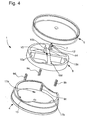
figure 4 est une vue en éclaté permettant de comprendre le mode d'assemblage des différents constituants de la boîte protectrice ; - la
figure 5 est une vue en coupe agrandie montrant le petit épaulement intérieur que présente la partie supérieure du rebord cylindrique.
- the
figure 1 is a perspective view of a protective box for transporting and storing a watch face corresponding to a particular embodiment of the present invention; - the
figure 2 is a sectional view of the protective box of thefigure 1 ; - the
figure 3 is an enlarged sectional view showing the cone and arms of the cleat constituting an example of clamping means according to the present invention; - the
figure 4 is an exploded view to understand the method of assembly of the various constituents of the protective box; - the
figure 5 is an enlarged sectional view showing the small inner shoulder that presents the upper portion of the cylindrical rim.
En se référant aux
Le fonctionnement de la boîte va maintenant être décrit en référance aux
Dès que l'abaissement du couvercle provoque la rencontre du cône 8 et du tasseau 7 (qui forment ensemble le dispositif de serrage), la pointe du cône va s'introduire à la manière d'un coin entre les quatres bras du tasseau. Le cône va ainsi pousser les quatre bras radialement de manière à ce qu'il s'écartent suffisament pour venir buter contre le bord intérieur du trou de centre du cadran 11, immobilisant ainsi le cadran.As soon as the lowering of the lid causes the
Dès que la pince formée par les quatre bras du tasseau presse contre les flancs du trou de centre, le tasseau 7 ne peut plus se déformer. C'est donc la flasque mobile 6 qui s'abaisse sous la pression du couvercle 3 en comprimant les ressorts 9a, 9b, 9c et 9d, jusqu'à ce que la boîte soit complètement fermée. A ce moment là, les rebords cylindriques 4 et 5 sont complètement emboîtés.As soon as the clamp formed by the four arms of the cleat press against the sides of the center hole, the
On comprendra que selon le principe de fonctionnement qui vient d'être décrit, l'élasticité du tasseau 7 et celle des moyens élastiques 9a, 9b, 9c et 9d assurant la suspension de la flasque 6 sont, en quelque sorte, en concurrence pour accompagner l'abbaissement du couvercle 3 et du cône 8. Il est donc important que les moyens élastiques soient suffisament résistants à la déformation pour permettre le calage des bras du tasseau 7 dans le trou de centre du cadran 11. Cela revient à dire qu'il est nécessaire que le tasseau soit plus souple que les moyens élastiques. Sans quoi, le diamètre du tasseau ne peut pas augmenter suffisament pour immobiliser le cadran.It will be understood that according to the operating principle which has just been described, the elasticity of the
Selon le mode de réalisation de l'invention qui fait l'objet du présent exemple, une même gamme de boîtes et prévue pour accommoder tous les modèles de cadran d'un fabriquant. De plus, dans le présent exemple, les différentes boîtes de la gamme se distinguent uniquement par les dimensions de leur tasseau. Comme les tasseaux sont interchangeables, on comprendra qu'il est possible de conditionner l'ensemble des cadrans d'un fabriquant avec le même modèle de boîte. Comme on va le voir plus en détail, selon le présent exemple, les tasseaux eux-mêmes peuvent être indentiques en tout point, exception faite du diamètre (extérieur et intérieur) de la pince formée par les bras du tasseau.According to the embodiment of the invention which is the subject of this example, the same range of boxes and provided to accommodate all dial models of a manufacturer. In addition, in the present example, the different boxes of the range are distinguished only by the dimensions of their cleat. As the cleats are interchangeable, it will be understood that it is possible to package all the dials of a manufacturer with the same model box. As will be seen in more detail, according to the present example, the cleats themselves can be identical in every way, except for the diameter (outside and inside) of the clamp formed by the arms of the cleat.
Supposons à titre d'exemple que les différents modèles de cadran que l'on désire conditionner à l'aide de boîtes selon la présente invention ont des épaisseurs au centre comprises entre 0.25mm et 1 mm. Suposons de plus que les diamètres des trous de cadran de ces cadrans sont compris entre 1.1 mm et 2.7mm. A titre d'exemple, on pourra choisir d'avoir quatre modèles de tasseau avec des diamètres de pince différents. Tous ces tasseaux pourront avoir la même hauteur de 1.1 mm de manière à pouvoir recevoir tous les cadrans :
- le premier modèle de tasseau pourra avoir une pince avec un diamètre extérieur de 1.05mm. Ce modèle pourra convenir pour des diamètres de trou de cadran compris entre environ 1.1 mm et 1.65mm.
- le deuxième modèle de tasseau pourra avoir une pince avec un diamètre de 1.45mm. Ce modèle pourra convenir pour des diamètres de trou de cadran compris entre environ 1.65mm et 1.9mm.
- le troisième modèle de tasseau pourra avoir une pince avec un diamètre de 1.65mm. Ce modèle pourra convenir pour des diamètres de trou de cadran compris entre environ 1.7mm et 2.3mm.
- le quatrième modèle de tasseau pourra avoir une pince avec un diamètre de 2.35mm. Ce modèle pourra convenir pour des diamètres de trou de cadran compris entre environ 2.4mm et 2.7mm.
- the first model of cleat can have a clamp with an outer diameter of 1.05mm. This model may be suitable for dial hole diameters of between 1.1 mm and 1.65 mm.
- the second model of cleat can have a clamp with a diameter of 1.45mm. This model may be suitable for dial hole diameters of between 1.65mm and 1.9mm.
- the third model of cleat can have a clamp with a diameter of 1.65mm. This model may be suitable for dial hole diameters between about 1.7mm and 2.3mm.
- the fourth model of cleat can have a clamp with a diameter of 2.35mm. This model may be suitable for dial hole diameters between approximately 2.4mm and 2.7mm.
Si comme dans le présent exemple, les tasseaux sont réalisés en téflon, l'épaisseur de la paroi de l'élément tubulaire du tasseau pourra être, par exemple, de 0.3mm pour le modèle de tasseau le plus petit. Pour les trois modèles plus grand, l'épaisseur de la paroi pourra être par exemple de 0.5mm.If, as in the present example, the cleats are made of Teflon, the thickness of the wall of the tubular element of the cleat may be, for example, 0.3mm for the smallest cleat model. For the three larger models, the thickness of the wall may for example be 0.5mm.
D'autre part, Le cône 8 est de préférence dimensionné de manière à garder un certain écartement entre le dessus d'un cadran et le dessous du couvercle, quel que soit le diamètre du trou de centre du cadran. Cette condition est respectée, par exemple, si le cône présente un angle au sommet de 90° et que sa base circulaire possède un diamètre de 3mm.On the other hand, the
On voit de plus, sur la
L'assemblage de la boîte va maintenant être décrit en s'appuyant sur les
La seconde opération consiste en le montage de la flasque 6 sur le fond. Le diamètre extérieur de la flasque et le diamètre intérieur du rebord 4 sont ajustés de manière à ce que la flasque puisse coulisser tout en étant maintenue latéralement. Toutefois, comme on l'a déjà dit, le rebord 4 présente, dans sa partie supérieure, un petit épaulement intérieur 16 prévu pour limiter la course de la flasque 6 et l'empècher de se désengager du rebord cylindrique 4. Le diamètre intérieur de l'épaulement 16 est légèrement inférieur au diamètre extérieur de la flasque 6. Dans ces conditions, lors de l'assemblage, pour introduire la flasque dans le fond 2, il est nécessaire de forcer le passage. Cette opération est rendue possible par l'élasticité du matériau dont sont faits le rebord 4 et le fond 2. Ce matériau peut être par exemple du polystirène.The second operation consists in mounting the
Quatre logements 10a, 10b, 10c et 10d, prévus chacun pour recevoir l'extrémité supérieure d'un des ressorts hélicoïdaux 9a, 9b, 9c et 9d, sont encore aménagés dans la partie inférieure de la flasque 6. Lors du montage, avant de chasser la flasque 6 dans le fond 2, il est nécessaire de prépositionner la flasque 6 au dessus du fond 2 avec les quatre logements à la verticale des ressorts. A cet effet, on voit sur la
Une fois la flasque 6 en place, l'étape suivante est le montage du tasseau 7 sur la flasque. Comme on l'a vu, dans le présent exemple, plusieurs modèles de tasseaux, avec des éléments tubulaires de diamètres différents, sont requis pour accommoder toute la gamme des cadrans existants. Dans le présent exemple, tous les modèles de tasseaux présentent une embase 14 de même diamètre. Cette caractéristique assure l'interchangeabilité des tasseaux.Once the
La flasque 6 présente au centre de sa face supérieure un logement constitué par un chambrage cylindrique 15 prévu pour recevoir le tasseau 7. Le diamètre intérieur du chambrage 15 correspond au diamètre extérieur de l'embase 14, de sorte que le tasseau puisse être chassé jusqu'au fond du chambrage et y être maintenu._L'introduction du tasseau dans le chambrage est de préférence effectuée avec un outil conçu de manière à éviter d'abîmer la pince du tasseau. Cette outil peut par exemple avoir la forme d'un tube entourant l'élément cylindrique du tasseau et venant en appui contre l'embase 14.The
On voit sur la figure 7 que le chambrage cylindrique 15 se prolonge du côté inférieur de la flasque par un trou circulaire 16 traversant. Le fond 2 de la boîte est également percé d'un trou 18 traversant disposé dans le prolongement de l'axe du chambrage 15. Grâce à la présence de ces deux trous alignés il est possible de retirer le tasseau 7 de la boîte sans qu'il soit nécessaire, au préalable, d'extraire la flasque 6 du fond 2. En effet, en insérant une goupille par le fond dans les trous 18 et 16, il est possible d'éjecter le tasseau 7 de son logement 15. Cette possibilité est utile par exemple lorsqu'on veut remplacer le tasseau en place par un tasseau de diamètre différent.It can be seen in FIG. 7 that the
On comprendra que diverses modifications et/ou améliorations évidentes pour un homme du métier peuvent être apportées au mode de réalisation décrit dans la description sans sortir du cadre de la présente invention définie par les revendications annexées.It will be understood that various modifications and / or improvements obvious to those skilled in the art can be made to the embodiment described in the description without departing from the scope of the present invention defined by the appended claims.
On pourra notamment prévoir dans d'autres modes de réalisation que flasque et tasseau viennent réalisés en une seule pièce, de façon à réduire les coûts de production. Dans ces conditions, on pourra par exemple adapter une boîte selon l'invention à une autre dimension de cadran simplement en changeant de flasque. On pourra aussi prévoir dans d'autres variantes de réalisation de réaliser le tasseau non pas sur la flasque mais sur le couvercle, dans ce cas le cone coopérant avec le tasseau sera arrangé sur la flasque.It may be provided in other embodiments that the flange and flange are made in one piece, so as to reduce production costs. Under these conditions, for example, a box according to the invention can be adapted to another dial dimension simply by changing the flange. It may also be provided in other embodiments to make the cleat not on the flange but on the cover, in this case the cone cooperating with the cleat will be arranged on the flange.
On pourra notamment prévoir d'utiliser la boîte selon l'invention pour conditionner d'autres pièces en forme de plaque que des cadrans de montre. On pense notamment à des supports d'informations sous forme de disques.In particular, it will be possible to use the box according to the invention for packaging other plate-shaped parts than watch dials. One thinks in particular of information carriers in the form of disks.
D'autre part, dans l'exemple de la description détaillée, le couvercle est transparent. Cette caractéristique présente l'avantage de permettre de lire des indications portées sur la face supérieure du cadran sans ouvrir la boîte. De plus, dans l'exemple, la flasque est ajourée. Cette caractéristique présente notamment l'avantage de permettre de conditionner des cadrans déjà munis de pied de cadran. D'autre part, si la caractéristique d'une flasque ajourée est combinée avec celle d'un fond transparent ou translucide, cette combinaison présente l'avantage de permettre l'indentification d'une référence ou d'un code barre éventuellement porté par la face inférieure du cadran.On the other hand, in the example of the detailed description, the cover is transparent. This feature has the advantage of allowing to read indications on the upper face of the dial without opening the box. In addition, in the example, the flange is perforated. This feature has the particular advantage of allowing to condition dials already equipped with dial feet. On the other hand, if the characteristic of a perforated flange is combined with that of a transparent or translucent background, this combination has the advantage of allowing the identification of a reference or a bar code possibly carried by the lower face of the dial.
Dans l'exemple de la description détaillée, les moyens élastiques pour rappeler la flasque en direction du couvercle sont des ressorts hélicoïdaux. On comprendra, toutefois, que tout autre forme de moyens de rappel connue de l'homme du métier est susceptible d'être utilisée dans la présente invention.In the example of the detailed description, the resilient means for biasing the flange towards the cover are helical springs. It will be understood, however, that any other form of return means known to those skilled in the art may be used in the present invention.
Enfin, pour faciliter la gestion des boîtes, il est possible de prévoir qu'elles portent un signe distinctif indiquant le diamètre du tasseau qu'elles contiennent.Finally, to facilitate the management of the boxes, it is possible to provide that they carry a distinctive sign indicating the diameter of the cleat they contain.
Claims (9)
- Protective case (1) for transporting or storing a plate-shaped part pierced with an aperture (11), including a back cover (2) and a cover (3), the back cover and the cover each having an edge (4, 5), and said edges fitting into each other when the case is closed, the case further including a flange (6) inserted in the back cover (2) and held laterally by the edge (4) thereof, and clamping means (7, 8) for immobilising the plate-shaped part, characterized in that the clamping means include an elastically deformable stake (7) that is mounted on the top surface of the flange (6) and is arranged to be inserted in the aperture in the plate-shaped part (11), the clamping means further including projecting portion (8) formed under the bottom surface of the cover (3), the projecting portion being arranges to press against the stake (7) when the case is closed so as to increase the external diameter of the stake so as to jam said stake in the aperture of the plate-shaped part (11 elastic means (9a, 9b, 9c, 9d) also being provided under the flange (6) to return the flange and the stake (7) that it carries in the direction of the cover (3) with sufficient force to hold the stake (7) jammed in the aperture of the plate-shaped part (11).
- Case according to claim 1, characterized in that the stake (7) has a longitudinally slit tubular element, the slit wall of the tubular element forming at least two elastic arms, and in that the projecting portion (8) formed under the cover is introduced into the slit tubular element like a wedge to separate said elastic arms so as to increase the external diameter of the stake.
- Case according to claim 1 or 2, characterized in that the stake (7) is integral with the flange (6).
- Case according to claim 1 or 2, characterized in that the stake (7) is parc that is added to the flange (6) and in that the diameter of the stake is determined in accordance with the diameter of the aperture of the plate-shaped part (11).
- Case according to any of the preceding claims, characterized in that the flange (6) is cut away.
- Case according to claim 5, characterized in that the back cover (2) is transparent.
- Case according tn any of the preceding claims, characterized in that the cover (3) is transparent.
- Case according to any of the preceding claims, characterized in that the elastic means that are provided for returning the flange in the direction of the cover are springs compressed between the back cover and the flange.
- Case according to any of the preceding claims, characterized in that it bears a distinctive sign indicating the diameter of the stake that it contains.
Applications Claiming Priority (2)
| Application Number | Priority Date | Filing Date | Title |
|---|---|---|---|
| CH19982006 | 2006-12-07 | ||
| PCT/EP2007/063351 WO2008068282A1 (en) | 2006-12-07 | 2007-12-05 | Protective box for transporting or storing a part in the form of a plate pierced by an opening |
Publications (2)
| Publication Number | Publication Date |
|---|---|
| EP2102074A1 EP2102074A1 (en) | 2009-09-23 |
| EP2102074B1 true EP2102074B1 (en) | 2011-11-02 |
Family
ID=39145047
Family Applications (1)
| Application Number | Title | Priority Date | Filing Date |
|---|---|---|---|
| EP07847843A Active EP2102074B1 (en) | 2006-12-07 | 2007-12-05 | Protective box for transporting or storing a part in the form of a plate pierced by an opening |
Country Status (7)
| Country | Link |
|---|---|
| US (1) | US8520474B2 (en) |
| EP (1) | EP2102074B1 (en) |
| JP (1) | JP5016059B2 (en) |
| CN (1) | CN101646612B (en) |
| AT (1) | ATE531644T1 (en) |
| HK (1) | HK1140991A1 (en) |
| WO (1) | WO2008068282A1 (en) |
Families Citing this family (5)
| Publication number | Priority date | Publication date | Assignee | Title |
|---|---|---|---|---|
| EP2144126A1 (en) * | 2008-07-10 | 2010-01-13 | Breitling AG | Work-piece carrier, system and method of transporting at least one piece, in particular for horology |
| EP2595008B1 (en) * | 2011-11-17 | 2015-01-07 | Montres Rado S.A. | Case for a clock piece |
| CH707808B1 (en) * | 2013-03-19 | 2017-05-15 | Nivarox Far Sa | Watch mechanism cassette. |
| EP2781966B1 (en) * | 2013-03-19 | 2018-05-02 | Nivarox-FAR S.A. | Anchor for clock escapement mechanism |
| CN105480588B (en) * | 2015-12-16 | 2018-01-16 | 天津市天门进保科技有限公司 | A kind of seal box of photoelectric detector |
Family Cites Families (37)
| Publication number | Priority date | Publication date | Assignee | Title |
|---|---|---|---|---|
| US646843A (en) * | 1897-10-06 | 1900-04-03 | Ernest Krahenbuhl | Watch-dial. |
| US1003132A (en) * | 1911-05-20 | 1911-09-12 | Metal Specialties Mfg Co | Balance-wheel holder. |
| DE592168C (en) | 1932-08-16 | 1934-02-02 | Hermann Tautz | Dummy for displaying food |
| US2313766A (en) * | 1941-05-01 | 1943-03-16 | Pfanstiehl Chemical Company | Container for phonograph needles and the like |
| US2380215A (en) * | 1944-09-26 | 1945-07-10 | Caldara Nicholas | Watch |
| US2719403A (en) * | 1951-07-14 | 1955-10-04 | Gisiger Armin | Tight container |
| FR1253107A (en) | 1960-04-05 | 1961-02-03 | Miremont | Packaging for clockwork balance |
| DE1825496U (en) | 1960-09-28 | 1961-01-19 | Kienzle Uhrenfabriken Ag | CONTAINER FOR COMPLETE VIBRATION SYSTEMS FOR UNRUH- WATCHES. |
| US3291134A (en) * | 1965-12-20 | 1966-12-13 | William H Novales | File prop |
| US3765249A (en) * | 1971-09-23 | 1973-10-16 | Dresser Ind | Gauge casing construction |
| CH598082A5 (en) | 1975-12-02 | 1978-04-28 | Robert Giavarini | Packaging for clock and watch dials |
| US4154110A (en) * | 1978-01-13 | 1979-05-15 | Sybron Corporation | Housing assembly for barometer or other instrument having a settable index |
| DE3205478A1 (en) * | 1982-02-16 | 1983-08-25 | Polygram Gmbh, 2000 Hamburg | STORAGE CASSETTE FOR DISK-SHAPED INFORMATION CARRIERS WITH HIGH STORAGE DENSITY |
| DE3301644A1 (en) * | 1983-01-19 | 1984-07-19 | Polygram Gmbh, 2000 Hamburg | STORAGE CASSETTE FOR TWO AND MORE DISK-SHAPED INFORMATION CARRIERS WITH HIGH STORAGE DENSITY |
| JP2521139Y2 (en) * | 1989-06-20 | 1996-12-25 | 株式会社吉野工業所 | Liquid dispenser |
| US5531321A (en) * | 1993-05-28 | 1996-07-02 | Ivy Hill Corporation | Glueless storage package |
| US5573120A (en) * | 1993-04-27 | 1996-11-12 | Pop-Pak, Limited | Storage container for compact discs and the like |
| DE9309103U1 (en) * | 1993-06-18 | 1993-08-12 | Cartonneries De Thulin S.A., Thulin, Be | |
| GB2291640B (en) * | 1994-11-03 | 1996-07-24 | Dubois Plc | Apparatus for holding a compact disk |
| CH687898B5 (en) * | 1995-04-25 | 1997-09-30 | Ebauchesfabrik Eta Ag | Watch with an electroluminescent dial. |
| DE19605336A1 (en) * | 1996-02-14 | 1997-08-21 | Polygram Manufacturing & Distr | Housing for receiving plate-shaped information carriers |
| WO1998017549A1 (en) * | 1996-10-21 | 1998-04-30 | Weingarden Marshall L | Storage container for information bearing disc devices |
| US5845771A (en) * | 1997-05-23 | 1998-12-08 | Fu; Hsin-Yu | Case for compact disks |
| JP3137934B2 (en) * | 1997-10-14 | 2001-02-26 | 高岡精工株式会社 | Disc body storage case |
| US5894924A (en) * | 1997-11-25 | 1999-04-20 | Koch; Hans G. | Alternative CD-ROM/DVD packaging device |
| DE20004218U1 (en) * | 1999-03-09 | 2000-07-27 | Chin Ta Ind Co | Device for storing CDs |
| JP4564638B2 (en) * | 2000-09-14 | 2010-10-20 | 株式会社ディスコ | Blade case |
| GB0024496D0 (en) * | 2000-10-05 | 2000-11-22 | Pettigrew Michael | New compact disc case |
| ES2294129T3 (en) * | 2001-02-20 | 2008-04-01 | Nexpak Corporation | STORAGE CONTAINER FOR RECORDED SUPPORT MEDIA. |
| US6805238B2 (en) * | 2001-07-27 | 2004-10-19 | Cammy Magnetech Company, Ltd. | Apparatus for holding a media storage disk |
| US20030150755A1 (en) * | 2002-02-11 | 2003-08-14 | Chen Kun Chang | Compact disk case |
| US7111729B2 (en) * | 2003-04-15 | 2006-09-26 | Finest Industrial Co., Ltd. | Low-profile disk case |
| US20050023179A1 (en) * | 2003-07-31 | 2005-02-03 | Albritton Charles Wade | Fragile-product cage for vacuum packaging appliances |
| JP2007527346A (en) * | 2004-03-05 | 2007-09-27 | ミードウエストベコ・コーポレーション | Storage package for storage media with improved rosette |
| JP2006054306A (en) * | 2004-08-11 | 2006-02-23 | Fanuc Ltd | Accommodation tool for transferring semiconductor wafer |
| JP2006199342A (en) * | 2005-01-20 | 2006-08-03 | Epson Toyocom Corp | Optical component-packing container |
| US8096702B2 (en) * | 2009-05-28 | 2012-01-17 | The Avalanche Group, Llc | Ornament container for watch |
-
2007
- 2007-12-05 CN CN2007800508394A patent/CN101646612B/en not_active Expired - Fee Related
- 2007-12-05 JP JP2009539746A patent/JP5016059B2/en not_active Expired - Fee Related
- 2007-12-05 EP EP07847843A patent/EP2102074B1/en active Active
- 2007-12-05 WO PCT/EP2007/063351 patent/WO2008068282A1/en active Application Filing
- 2007-12-05 AT AT07847843T patent/ATE531644T1/en active
- 2007-12-05 US US12/518,205 patent/US8520474B2/en not_active Expired - Fee Related
-
2010
- 2010-08-09 HK HK10107594.3A patent/HK1140991A1/en not_active IP Right Cessation
Also Published As
| Publication number | Publication date |
|---|---|
| HK1140991A1 (en) | 2010-10-29 |
| WO2008068282A1 (en) | 2008-06-12 |
| ATE531644T1 (en) | 2011-11-15 |
| US8520474B2 (en) | 2013-08-27 |
| JP2010529933A (en) | 2010-09-02 |
| EP2102074A1 (en) | 2009-09-23 |
| CN101646612A (en) | 2010-02-10 |
| US20100108697A1 (en) | 2010-05-06 |
| JP5016059B2 (en) | 2012-09-05 |
| CN101646612B (en) | 2011-08-17 |
Similar Documents
| Publication | Publication Date | Title |
|---|---|---|
| EP2102074B1 (en) | Protective box for transporting or storing a part in the form of a plate pierced by an opening | |
| EP1035922A1 (en) | Rack comprising refills for stacked pipette tips | |
| LU82241A1 (en) | FOOD CONTAINERS | |
| WO2019030451A2 (en) | Device for packaging an object, assembly and corresponding extraction method | |
| WO2012045972A1 (en) | Reaction vessel for an automatic chemical or biological analysis device | |
| EP1406041A2 (en) | Security device for puncturable cartridge | |
| WO2005056958A1 (en) | Anti-theft device | |
| FR2969130A1 (en) | Liquid i.e. wine, dispensing device, has container formed of two half housings complementary to each other, where each housing half includes notch partially complementary to valve and hole of container is formed by cooperation of notch | |
| EP2058579A2 (en) | Removable protective enclosure for a tank containing fluid under pressure, suitable removal tool and use of such a tool | |
| FR3061484B1 (en) | BOTTLE BOX COMPRISING MEANS FOR RETAINING THE BOTTLE | |
| FR2967663A1 (en) | Suspension device for suspending open bags in container of dust bin, has suspension elements suspending open bags, where bags are rolled up and pinched between suspension elements and upper edge of container | |
| EP0836822B1 (en) | Packaging and display device for jewelry and support or storage element to be used therein | |
| FR2898109A1 (en) | Load supporting pallet`s plate for loading power lift truck yoke, has case for housing retractable stop comprising stop body with pivoting unit which cooperates with another pivoting unit of case to form articulation between two positions | |
| FR3020802A1 (en) | NON-DESOLIDARIZABLE COVER FOR CONTAINER AND CONTAINER EQUIPPED WITH SUCH SHELL | |
| WO2022189721A1 (en) | Opening device with an integrated straw, and method for manufacturing the device | |
| BE1008306A6 (en) | Disc storage case | |
| FR3079823A1 (en) | STORAGE AND PROTECTION BOX OF GEOMETRY INSTRUMENTS | |
| FR2950031A1 (en) | Package for transporting and dispatching objects i.e. postal, has side beams including integration units for integrating cover by providing pressure to base plate, where beams supports pressure applied to integrate cover with side walls | |
| FR3120217A1 (en) | Device for holding an electronic device with a concave surface and associated assembly | |
| EP4258930A1 (en) | Transport package | |
| FR2706331A1 (en) | Device for helping to empty boxes containing letters (items of mail) | |
| EP4027941A1 (en) | Assembly for handling multiple straws for packaging animal semen | |
| FR3126606A1 (en) | Cup for a beverage dispensing machine | |
| FR3120215A1 (en) | Device for holding an electronic device comprising two parts and associated assembly | |
| WO2021048223A1 (en) | Support element for a plurality of animal semen packaging straws and assembly comprising said support element |
Legal Events
| Date | Code | Title | Description |
|---|---|---|---|
| PUAI | Public reference made under article 153(3) epc to a published international application that has entered the european phase |
Free format text: ORIGINAL CODE: 0009012 |
|
| 17P | Request for examination filed |
Effective date: 20090707 |
|
| AK | Designated contracting states |
Kind code of ref document: A1 Designated state(s): AT BE BG CH CY CZ DE DK EE ES FI FR GB GR HU IE IS IT LI LT LU LV MC MT NL PL PT RO SE SI SK TR |
|
| DAX | Request for extension of the european patent (deleted) | ||
| GRAP | Despatch of communication of intention to grant a patent |
Free format text: ORIGINAL CODE: EPIDOSNIGR1 |
|
| GRAS | Grant fee paid |
Free format text: ORIGINAL CODE: EPIDOSNIGR3 |
|
| GRAA | (expected) grant |
Free format text: ORIGINAL CODE: 0009210 |
|
| AK | Designated contracting states |
Kind code of ref document: B1 Designated state(s): AT BE BG CH CY CZ DE DK EE ES FI FR GB GR HU IE IS IT LI LT LU LV MC MT NL PL PT RO SE SI SK TR |
|
| REG | Reference to a national code |
Ref country code: GB Ref legal event code: FG4D Free format text: NOT ENGLISH |
|
| REG | Reference to a national code |
Ref country code: CH Ref legal event code: EP |
|
| REG | Reference to a national code |
Ref country code: IE Ref legal event code: FG4D |
|
| REG | Reference to a national code |
Ref country code: DE Ref legal event code: R096 Ref document number: 602007018515 Country of ref document: DE Effective date: 20120119 |
|
| REG | Reference to a national code |
Ref country code: CH Ref legal event code: NV Representative=s name: ICB INGENIEURS CONSEILS EN BREVETS SA |
|
| REG | Reference to a national code |
Ref country code: NL Ref legal event code: VDEP Effective date: 20111102 |
|
| LTIE | Lt: invalidation of european patent or patent extension |
Effective date: 20111102 |
|
| PG25 | Lapsed in a contracting state [announced via postgrant information from national office to epo] |
Ref country code: LT Free format text: LAPSE BECAUSE OF FAILURE TO SUBMIT A TRANSLATION OF THE DESCRIPTION OR TO PAY THE FEE WITHIN THE PRESCRIBED TIME-LIMIT Effective date: 20111102 Ref country code: IS Free format text: LAPSE BECAUSE OF FAILURE TO SUBMIT A TRANSLATION OF THE DESCRIPTION OR TO PAY THE FEE WITHIN THE PRESCRIBED TIME-LIMIT Effective date: 20120302 |
|
| PG25 | Lapsed in a contracting state [announced via postgrant information from national office to epo] |
Ref country code: SE Free format text: LAPSE BECAUSE OF FAILURE TO SUBMIT A TRANSLATION OF THE DESCRIPTION OR TO PAY THE FEE WITHIN THE PRESCRIBED TIME-LIMIT Effective date: 20111102 Ref country code: PL Free format text: LAPSE BECAUSE OF FAILURE TO SUBMIT A TRANSLATION OF THE DESCRIPTION OR TO PAY THE FEE WITHIN THE PRESCRIBED TIME-LIMIT Effective date: 20111102 Ref country code: SI Free format text: LAPSE BECAUSE OF FAILURE TO SUBMIT A TRANSLATION OF THE DESCRIPTION OR TO PAY THE FEE WITHIN THE PRESCRIBED TIME-LIMIT Effective date: 20111102 Ref country code: PT Free format text: LAPSE BECAUSE OF FAILURE TO SUBMIT A TRANSLATION OF THE DESCRIPTION OR TO PAY THE FEE WITHIN THE PRESCRIBED TIME-LIMIT Effective date: 20120302 Ref country code: GR Free format text: LAPSE BECAUSE OF FAILURE TO SUBMIT A TRANSLATION OF THE DESCRIPTION OR TO PAY THE FEE WITHIN THE PRESCRIBED TIME-LIMIT Effective date: 20120203 Ref country code: LV Free format text: LAPSE BECAUSE OF FAILURE TO SUBMIT A TRANSLATION OF THE DESCRIPTION OR TO PAY THE FEE WITHIN THE PRESCRIBED TIME-LIMIT Effective date: 20111102 Ref country code: NL Free format text: LAPSE BECAUSE OF FAILURE TO SUBMIT A TRANSLATION OF THE DESCRIPTION OR TO PAY THE FEE WITHIN THE PRESCRIBED TIME-LIMIT Effective date: 20111102 |
|
| REG | Reference to a national code |
Ref country code: IE Ref legal event code: FD4D |
|
| PG25 | Lapsed in a contracting state [announced via postgrant information from national office to epo] |
Ref country code: CY Free format text: LAPSE BECAUSE OF FAILURE TO SUBMIT A TRANSLATION OF THE DESCRIPTION OR TO PAY THE FEE WITHIN THE PRESCRIBED TIME-LIMIT Effective date: 20111102 |
|
| BERE | Be: lapsed |
Owner name: MONTRES BREGUET SA MANUFACTURE Effective date: 20111231 |
|
| PG25 | Lapsed in a contracting state [announced via postgrant information from national office to epo] |
Ref country code: EE Free format text: LAPSE BECAUSE OF FAILURE TO SUBMIT A TRANSLATION OF THE DESCRIPTION OR TO PAY THE FEE WITHIN THE PRESCRIBED TIME-LIMIT Effective date: 20111102 Ref country code: CZ Free format text: LAPSE BECAUSE OF FAILURE TO SUBMIT A TRANSLATION OF THE DESCRIPTION OR TO PAY THE FEE WITHIN THE PRESCRIBED TIME-LIMIT Effective date: 20111102 Ref country code: DK Free format text: LAPSE BECAUSE OF FAILURE TO SUBMIT A TRANSLATION OF THE DESCRIPTION OR TO PAY THE FEE WITHIN THE PRESCRIBED TIME-LIMIT Effective date: 20111102 Ref country code: MC Free format text: LAPSE BECAUSE OF NON-PAYMENT OF DUE FEES Effective date: 20111231 Ref country code: BG Free format text: LAPSE BECAUSE OF FAILURE TO SUBMIT A TRANSLATION OF THE DESCRIPTION OR TO PAY THE FEE WITHIN THE PRESCRIBED TIME-LIMIT Effective date: 20120202 Ref country code: IE Free format text: LAPSE BECAUSE OF FAILURE TO SUBMIT A TRANSLATION OF THE DESCRIPTION OR TO PAY THE FEE WITHIN THE PRESCRIBED TIME-LIMIT Effective date: 20111102 Ref country code: SK Free format text: LAPSE BECAUSE OF FAILURE TO SUBMIT A TRANSLATION OF THE DESCRIPTION OR TO PAY THE FEE WITHIN THE PRESCRIBED TIME-LIMIT Effective date: 20111102 |
|
| PG25 | Lapsed in a contracting state [announced via postgrant information from national office to epo] |
Ref country code: IT Free format text: LAPSE BECAUSE OF FAILURE TO SUBMIT A TRANSLATION OF THE DESCRIPTION OR TO PAY THE FEE WITHIN THE PRESCRIBED TIME-LIMIT Effective date: 20111102 Ref country code: RO Free format text: LAPSE BECAUSE OF FAILURE TO SUBMIT A TRANSLATION OF THE DESCRIPTION OR TO PAY THE FEE WITHIN THE PRESCRIBED TIME-LIMIT Effective date: 20111102 |
|
| PLBE | No opposition filed within time limit |
Free format text: ORIGINAL CODE: 0009261 |
|
| STAA | Information on the status of an ep patent application or granted ep patent |
Free format text: STATUS: NO OPPOSITION FILED WITHIN TIME LIMIT |
|
| REG | Reference to a national code |
Ref country code: AT Ref legal event code: MK05 Ref document number: 531644 Country of ref document: AT Kind code of ref document: T Effective date: 20111102 |
|
| 26N | No opposition filed |
Effective date: 20120803 |
|
| GBPC | Gb: european patent ceased through non-payment of renewal fee |
Effective date: 20120202 |
|
| PG25 | Lapsed in a contracting state [announced via postgrant information from national office to epo] |
Ref country code: BE Free format text: LAPSE BECAUSE OF NON-PAYMENT OF DUE FEES Effective date: 20111231 |
|
| REG | Reference to a national code |
Ref country code: DE Ref legal event code: R097 Ref document number: 602007018515 Country of ref document: DE Effective date: 20120803 |
|
| PG25 | Lapsed in a contracting state [announced via postgrant information from national office to epo] |
Ref country code: AT Free format text: LAPSE BECAUSE OF FAILURE TO SUBMIT A TRANSLATION OF THE DESCRIPTION OR TO PAY THE FEE WITHIN THE PRESCRIBED TIME-LIMIT Effective date: 20111102 Ref country code: GB Free format text: LAPSE BECAUSE OF NON-PAYMENT OF DUE FEES Effective date: 20120202 |
|
| PG25 | Lapsed in a contracting state [announced via postgrant information from national office to epo] |
Ref country code: MT Free format text: LAPSE BECAUSE OF FAILURE TO SUBMIT A TRANSLATION OF THE DESCRIPTION OR TO PAY THE FEE WITHIN THE PRESCRIBED TIME-LIMIT Effective date: 20111102 |
|
| PG25 | Lapsed in a contracting state [announced via postgrant information from national office to epo] |
Ref country code: ES Free format text: LAPSE BECAUSE OF FAILURE TO SUBMIT A TRANSLATION OF THE DESCRIPTION OR TO PAY THE FEE WITHIN THE PRESCRIBED TIME-LIMIT Effective date: 20120213 |
|
| PG25 | Lapsed in a contracting state [announced via postgrant information from national office to epo] |
Ref country code: LU Free format text: LAPSE BECAUSE OF NON-PAYMENT OF DUE FEES Effective date: 20111205 |
|
| PG25 | Lapsed in a contracting state [announced via postgrant information from national office to epo] |
Ref country code: FI Free format text: LAPSE BECAUSE OF FAILURE TO SUBMIT A TRANSLATION OF THE DESCRIPTION OR TO PAY THE FEE WITHIN THE PRESCRIBED TIME-LIMIT Effective date: 20111102 |
|
| PG25 | Lapsed in a contracting state [announced via postgrant information from national office to epo] |
Ref country code: TR Free format text: LAPSE BECAUSE OF FAILURE TO SUBMIT A TRANSLATION OF THE DESCRIPTION OR TO PAY THE FEE WITHIN THE PRESCRIBED TIME-LIMIT Effective date: 20111102 |
|
| PG25 | Lapsed in a contracting state [announced via postgrant information from national office to epo] |
Ref country code: HU Free format text: LAPSE BECAUSE OF FAILURE TO SUBMIT A TRANSLATION OF THE DESCRIPTION OR TO PAY THE FEE WITHIN THE PRESCRIBED TIME-LIMIT Effective date: 20111102 |
|
| REG | Reference to a national code |
Ref country code: FR Ref legal event code: PLFP Year of fee payment: 9 |
|
| REG | Reference to a national code |
Ref country code: FR Ref legal event code: PLFP Year of fee payment: 10 |
|
| REG | Reference to a national code |
Ref country code: FR Ref legal event code: PLFP Year of fee payment: 11 |
|
| PGFP | Annual fee paid to national office [announced via postgrant information from national office to epo] |
Ref country code: CH Payment date: 20230101 Year of fee payment: 16 |
|
| P01 | Opt-out of the competence of the unified patent court (upc) registered |
Effective date: 20230611 |
|
| PGFP | Annual fee paid to national office [announced via postgrant information from national office to epo] |
Ref country code: FR Payment date: 20231122 Year of fee payment: 17 Ref country code: DE Payment date: 20231121 Year of fee payment: 17 |