EP2102071B1 - Dispositif d'irremplissabilite pour goulot de recipient - Google Patents
Dispositif d'irremplissabilite pour goulot de recipient Download PDFInfo
- Publication number
- EP2102071B1 EP2102071B1 EP07871800.4A EP07871800A EP2102071B1 EP 2102071 B1 EP2102071 B1 EP 2102071B1 EP 07871800 A EP07871800 A EP 07871800A EP 2102071 B1 EP2102071 B1 EP 2102071B1
- Authority
- EP
- European Patent Office
- Prior art keywords
- transverse wall
- refilling device
- neck
- wall
- typically
- Prior art date
- Legal status (The legal status is an assumption and is not a legal conclusion. Google has not performed a legal analysis and makes no representation as to the accuracy of the status listed.)
- Not-in-force
Links
Images





Classifications
-
- B—PERFORMING OPERATIONS; TRANSPORTING
- B65—CONVEYING; PACKING; STORING; HANDLING THIN OR FILAMENTARY MATERIAL
- B65D—CONTAINERS FOR STORAGE OR TRANSPORT OF ARTICLES OR MATERIALS, e.g. BAGS, BARRELS, BOTTLES, BOXES, CANS, CARTONS, CRATES, DRUMS, JARS, TANKS, HOPPERS, FORWARDING CONTAINERS; ACCESSORIES, CLOSURES, OR FITTINGS THEREFOR; PACKAGING ELEMENTS; PACKAGES
- B65D49/00—Arrangements or devices for preventing refilling of containers
- B65D49/02—One-way valves
-
- B—PERFORMING OPERATIONS; TRANSPORTING
- B65—CONVEYING; PACKING; STORING; HANDLING THIN OR FILAMENTARY MATERIAL
- B65D—CONTAINERS FOR STORAGE OR TRANSPORT OF ARTICLES OR MATERIALS, e.g. BAGS, BARRELS, BOTTLES, BOXES, CANS, CARTONS, CRATES, DRUMS, JARS, TANKS, HOPPERS, FORWARDING CONTAINERS; ACCESSORIES, CLOSURES, OR FITTINGS THEREFOR; PACKAGING ELEMENTS; PACKAGES
- B65D49/00—Arrangements or devices for preventing refilling of containers
-
- B—PERFORMING OPERATIONS; TRANSPORTING
- B65—CONVEYING; PACKING; STORING; HANDLING THIN OR FILAMENTARY MATERIAL
- B65D—CONTAINERS FOR STORAGE OR TRANSPORT OF ARTICLES OR MATERIALS, e.g. BAGS, BARRELS, BOTTLES, BOXES, CANS, CARTONS, CRATES, DRUMS, JARS, TANKS, HOPPERS, FORWARDING CONTAINERS; ACCESSORIES, CLOSURES, OR FITTINGS THEREFOR; PACKAGING ELEMENTS; PACKAGES
- B65D49/00—Arrangements or devices for preventing refilling of containers
- B65D49/12—Arrangements or devices for preventing refilling of containers by destroying, in the act of opening the container, an integral portion thereof
Definitions
- the invention relates to the field of capping capsules, and more particularly that of anti-fraud capping capsules for packaging liquid products of great value or of great renown, typically in the field of wines, alcohols, liqueurs or spirits. .
- anti-fraud to the refilling function, preventing or signaling any fraudulent reuse of a container by filling a different liquid from the original liquid.
- the term “inviolability” will be reserved for the "first opening control” function, generally provided by a strip or skirt connected to the capsule by a line of breakable bridges, also called “line of weakening", which is detached during of the first opening.
- a first object according to the invention is an irreplacability device, intended to be irreversibly fixed to the neck of a container containing a liquid and to be closed by a closure cap, said device having an axis coinciding with the axis.
- said neck when attached thereto, characterized in that it has an axial distribution duct of said liquid traversed by a transverse wall irreversibly fixed to said non-refill device and provided with a plurality of through channels, each of said through channels connecting an outer orifice, facing the outside of the container, to an inner orifice, facing the interior of the container, the smallest dimension of said external orifice being smaller than a critical dimension determined according to the tension of the critical surface of the constituent material of said transverse wall and wherein the smallest dimension of said inner port is greater than said critical dimension.
- the through channels have a variable section, this section can be defined by two extreme dimensions, measured along the main directions of said section.
- This section evolves from the inside of the container to the outside so that the smallest dimension decreases to a value below a critical value which depends on many parameters, among which the ability of the liquid to wet the surface of the transverse wall seems the most important parameter.
- This critical value is also a function of the viscosity of the liquid, but the latter is generally an alcohol to drink, typically a cognac, and has almost always the same viscous behavior.
- the critical surface tension of a material is associated with the wettability of this material.
- the wetting of the transverse wall depends primarily on the liquid surface tension and the critical surface tension of the material constituting the transverse wall.
- the critical surface tension of solid substrates can be determined by the method of measuring the contact angle. A very rapid determination of approximate values can be made by means of special test-inks (for example, according to ASTM Method 0 2578/67).
- the applicant has found that it was first necessary to control the size of the smallest dimension of the orifice: outer side, the edges and the wall of the channels not being, or being badly wetted by said liquid due to the critical surface tension of the material of the transverse wall, the latter can not penetrate easily into the through channel.
- the edges and the entrance of the wall of the through channels are more easily wetted: the liquid can enter the channel and cross it to the outlet orifice and eject it through the dynamic effect of the flow of the liquid and the pressure of the column of liquid still contained in the bottle.
- the smallest dimension of the external orifice must be certainly less but as close as possible to the said critical value.
- said transverse wall is made of a plastic material having a surface tension of between 25 and 50 mN / m and the smallest dimension of the outer orifices of the through channels is less than 0.7 mm, while the smaller dimension of their inner holes are greater than 0.7 mm. More preferably, the smallest dimension of the outer orifices is less than 0.6 mm, which makes the fraud even more difficult.
- the smallest dimension of the internal orifices is greater than 0.8 mm, which facilitates the flow of the liquid contained in the bottle.
- the transverse wall is substantially perpendicular to the axis of said device.
- the central portion of said transverse wall is present in the form of a grid having a network of through channels with sections whose form factor, defined by the ratio of the largest dimension on the smallest dimension, is less than 2, preferably close to 1.
- the inner holes have a square or rectangular shape.
- Said transverse wall may be flat.
- said through channels are all oriented substantially along the axis. In another embodiment, they are all inclined at an angle ⁇ with respect to the axial direction of the device, the angle a being typically between 30 and 60 °. In yet another embodiment said so-called through channels are composed of two axial portions communicating with each other but offset from each other with respect to the axis.
- Said transverse wall may also be curved and have its convexity towards the outside, typically having the shape of a hemispherical dome.
- the through channels are then preferably inclined relative to the direction normal to said transverse wall so that they remain substantially parallel to said axial direction.
- transverse wall makes it possible to prevent or at least to report any fraudulent reuse of the container by filling a liquid different from the original liquid: to fraudulently introduce this liquid, it is necessary to inject it under pressure while having to leave to escape the air contained in the bottle.
- the said transverse wall is given appropriate mechanical properties, the forces to be brought into play necessarily entail a destruction of the said wall.
- the invention therefore becomes particularly advantageous if said transverse wall is made of a sufficiently rigid and fragile material so that any fraudulent attempt to refill said container is made visible by the destruction or alteration of all or part of said transverse wall.
- said transverse wall is made of polyethylene terephthalate (PET) or polystyrene (PS), in particular impact polystyrene (SB) or crystal polystyrene. It has a thickness of between 0.5 and 2 mm.
- a molded one-piece device comprising a substantially cylindrical side wall to which said transverse wall is connected by means of a plurality of easily scored N bridges, N being preferably less than 12, of unit section less than 2 mm 2 , preferably less than 1 mm 2 .
- said transverse wall comprises in central part a grid provided with said plurality of through channels and at the periphery a plurality of curvilinear slots, the smallest dimension of which is smaller than said critical dimension, typically for a transverse plastic wall, less than 0.7 mm, and preferably less than 0.6 mm.
- the plurality of curvilinear slots is delimited by a crown attached to said side wall by easily broken outer bridges and the said grid by inner bridges also easily scored.
- each plurality of inner and outer bridges is regularly distributed and preferably angularly offset by ⁇ / N relative to the other plurality of bridges, N being preferably less than 12, of unit section less than 2 mm 2 , preferably less than 1 mm 2 .
- the non-refillable device according to the invention is advantageously assembled to a closure cap comprising at least one metal shell provided with a metal skirt. It comprises a temporary or removable securing means, typically a screw thread or a reversible snap-fitting bead, intended to cooperate with said composite closure cap.
- said metal skirt is provided with a complementary temporary securing means or is assembled to an insert provided with said complementary temporary securing means.
- an autonomous assembly which comprises the closure cap itself and the non-refill device and which can be fixed on the neck in a single step during capping of the container, typically by axial depression or by screwing.
- said wall is given a cylindrical diameter substantially equal to that of the inner diameter of said metal skirt, and it is provided with a peripheral annular groove, so that said device can be introduced into said shell and secured thereto, typically by formation of a crimping ring.
- the metal skirt is provided with an annular line of weakness which separates the metal shell in an upper part and a lower part. After breaking the weakening zone, the upper part is part of the removable cap closure and the lower part, crimped either on the neck or on the bottom of the refill device, remains attached to the bottle.
- the upper part is advantageously irreversibly secured to the lower part by the cooperation of complementary assembly means belonging to each of the two parts or by the introduction of the collar which serves to fix the device on the neck and which in the occurrence also serves as an outer ring of solidarity.
- the lower part preferably comprises a central portion obstructing said cavity, typically at its upper part, so as to trap said moving means of said non-return means in said cavity. It also includes an interior wall, with a lower lip delimiting a typically circular lower orifice of surface S 0 typically ranging from 50 to 150 mm 2. Said lower lip forms a seat cooperating with said movable part, so as to form said non-return valve, said moving part tending by gravity to close said lower orifice being pressed against said lower lip when said container is typically straight, and to separating axially from said lower seat and thus opening said lower orifice when said container is inclined to pour said liquid.
- the lower part also comprises a transverse wall intended to form an axial stop during the attachment of said refilling device to said neck, said transverse wall bearing against the rim of said neck, so as to ensure automatic axial positioning of said device relative to said neck during said fixing.
- the central part of the lower part advantageously comprises said axial duct which carries said cylindrical wall provided with at least one circular fin intended to cooperate with the inner wall of the neck.
- said transverse wall arriving in abutment on the rim of the neck and on which is fixed a flexible lip forming a pourer, typically with a thinned portion forming an annular hinge.
- the lower part comprises an axial central part, the upper part is provided with a central wall on which said transverse wall is fixed and the axial distribution duct is provided with an irreversible joining means, typically a bead.
- the central part of the lower part is provided with reversible securing means cooperating with those of the closure cap and the axial central portion of the upper piece is a sleeve inside which said means for temporarily securing the lower part. and said means for temporarily securing the capsule can move and cooperate.
- the periphery of the lower part of the transverse wall is preferably fixed on the internal face of a sleeve belonging to the upper part.
- the lower part also comprises a protection means preventing access to the non-return means, positioned above the central part of the lower part.
- Said protection means is for example a solid metal pellet which can move between the upper orifice of the lower piece and a ring which is connected to the lower piece by a plurality of axial arms surrounding said upper orifice, and whose internal diameter is less than the diameter of said solid pellet.
- Another object of the invention is an assembly of a closure cap and a non-refill device, said device being temporarily or removably assembled to said closure cap, so as to be able to assemble in a single step , at said neck, during the capping of said container, said non-refill device and said closure cap.
- Another object of the invention is a composite closure capsule comprising a closure cap and the non-refill device according to the invention, said device being temporarily or removably assembled to said closure cap, characterized in that said capsule capping includes a metal shell with a metal skirt.
- said skirt comprises at least one weakening line annular, and a crimping zone, typically annular, said line of weakness being located above said crimping zone, said weakening line being intended to facilitate a first opening of said capsule or to form an indication of first opening of said capsule, after said composite closure cap has closed said neck of said container during a capping phase of said container, said line of weakness delimiting an upper portion of said shell above said line of weakness and a lower part of said shell located below said line of weakness, said lower part being crimped to said lower part typically by embossing or crimping of said lower part in an annular groove of said outer wall, or being intended to be crimped on the neck, under his glass ring.
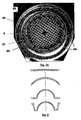
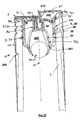
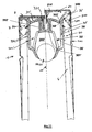
- FIG. 1 a illustrates the characteristics common to all the non-refillable devices according to the invention: said device has an axis (10) which coincides with the axis of the neck (40) of the container when it is fixed thereon. It has an axial conduit (39) for dispensing said liquid through which a transverse wall (6) is fixed irreversibly to said non-refill device (3) and provided with a plurality of through channels (63). Each of the through channels (63) connects an outer port (60) facing the outside of the container to an inner port (61) facing the interior of the container.
- the smallest dimension of said outer orifice (60) is chosen so that it remains smaller than a critical dimension determined as a function of the critical surface tension of the material constituting said transverse wall.
- the smallest dimension of said inner orifice (61) is chosen to be greater than said critical dimension.
- the transverse wall (6) is made of a plastic material which has a critical surface tension of between 25 and 50 mN / m.
- the smallest dimension of said outer orifice (60) is less than 0.6 mm and the smallest dimension of said inner orifice is greater than 0.8 mm.
- the transverse wall (6) present in the form of a grid having a network of through channels having approximately square sections which gradually decrease from the inside to the outside.
- the transverse wall (6) is curved and has its convexity outwardly, typically having the shape of a hemispherical dome. It is made of a sufficiently rigid and fragile material that any fraudulent attempt to refill said container is made visible by the destruction or alteration of all or part of said transverse wall.
- the device and the transverse wall are molded in one piece, of a material such as shock polystyrene or crystal polystyrene.
- the axial distribution duct (39) and the transverse wall (6) are connected via a plurality of bridges (65) whose section is less than 1 mm 2 .
- the transverse wall (6) comprises in the central part a grid provided with said plurality of through channels (63) and at the periphery a plurality of curvilinear slots (64), the smallest dimension of which is less than 0.6 mm.
- Said plurality of curvilinear slots is delimited by a ring gear (67) attached to said axial duct (39) by 8 regularly distributed outer bridges (65) and said grid (6) by 8 regularly spaced inner bridges (66) angularly offset from each other. ⁇ / 8 with respect to the outer bridges (67).
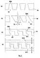
- the transverse wall (6a) is presented flat and perpendicular to the axis, as the walls illustrated in FIG. figure 3 .
- the through channels (63) are axial, that is, oriented substantially in a direction normal to said transverse wall as illustrated in FIG. figure 3 a) . In other embodiments, they are inclined differently so as to prevent, or at least impede, the introduction of a tapered object towards the interior of the container.
- case b) of the figure 3a illustrates channels inclined at an angle ⁇ with respect to the axial direction (10) of the device (3), the angle ⁇ being typically between 30 and 60 °.
- the through channels (63) are composed of two axial prismatic parts (630, 631) communicating with each other but offset from each other with respect to the axis.
- the inwardly oriented portion (631) has an upper section.
- figure 3d we schematically represented the molding tool to obtain the transverse wall shown in 3c.
- the wall is curved in the form of a hemispherical dome.
- the transverse wall is in the form of a portion of an annular ring or hemispherical dome without a central portion, the latter being occupied by the central axial portion (310 ') of the upper piece (31') of the device.
- the set of non-refillable devices according to the invention have a cylindrical wall (36, 36 ') provided with at least one irreversible fastening means to said neck.
- said cylindrical wall (36) has an internal diameter greater than the outer diameter of the glass ring and the irreversible fixing means is a hook (360) cooperating with the attachment zone (405) of the counter-ring. (403).
- said cylindrical wall (36) has an internal diameter greater than the outer diameter of the glass ring and said irreversible fixing means comprises at least one metal collar (38) which surrounds said cylindrical wall (36) and which is integral with the latter, said collar being intended to be crimped on the attachment zone (404) of the counter-ring (403).
- the flange (38) has been secured to said cylindrical wall (36) by at least one crimping on an upper peripheral annular shoulder (362) adjacent to said cylindrical wall (36).
- said cylindrical wall (36 ') has an external diameter less than the internal diameter of the neck (40) and said irreversible fixing means comprises at least one circular fin (334) intended to cooperate with said inner wall of the neck, its end being, when the device is not yet introduced into said neck at a distance from the axis (10) greater than said inner diameter of the neck. It may comprise a complementary attachment means (7) to the neck (40) comprising either an adhesive (70) carried by the surface of said fin (334) ( figure 10 ) is an elastomer ring seal (71) placed on the cylindrical wall (36 ') ( figure 11 ), or both, so as to ensure the sealing of said device (3) to said neck (40).
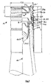
- capsules of figures 4 , 5 , 6 , 7 , 9 , 10 and 11 are inviolable composite capsules (1).
- the non-refill device is provided with a temporary securing means, typically a screw thread (370) ( Figures 4 to 7 and 9 ) or a reversible snap-in bead (371) ( figures 10 and 11 ), intended to cooperate with the closure cap (2).
- a temporary securing means typically a screw thread (370) ( Figures 4 to 7 and 9 ) or a reversible snap-in bead (371) ( figures 10 and 11 ), intended to cooperate with the closure cap (2).
- the latter comprises a metal shell (20) of which said metal skirt (200) is provided with a complementary temporary securing means (204) ( figure 7 ) or which is assembled to an insert (21) or a shutter (21 ') provided with said complementary temporary fastening means (214 complementary to 370, figure 4 (identical system in the examples of figures 5 , 6 , 8 and 9 ), (214 'complementary to 371, figures 10 and 11 ).
- Temporary assembly of the refill device and the capsule forms a "ready-
- the composite capsule is placed on the neck by axial depression until the transverse portion (34, 34 ') of the lower piece (30, 30') abuts the rim (400). ) (with the exception of the figure 4 , which is monobloc and therefore does not have a lower part, but for which fixing is done in the same way, mutatis mutandis).
- the devices "out bore” figures 4 , 5 and 6 are snapped onto the glass ring.
- the skirt (200) of the metal shell (20) is crimped on the attachment zone (404) of the counter-ring (403).
- the skirt (200) of the shell (20) is provided with a weakening band (201).
- the weakening line (201) is intended to facilitate a first opening of the capsule (2) or to form an indication of first opening of said capsule (2). It delimits an upper portion (202) of the shell (20), located above said line of weakness (201), and a lower portion (203) of said shell (20) located below said line of weakening (201).
- the lower portion (203) has a zone (205) which is crimped to the neck under its glass ring (401).
- the lower part (203) has a zone (206) which is crimped on the lower part (30), in an annular groove (361) of the outer wall (36). ).
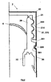
- This device comprises an upper piece (31, 31 ') carrying said transverse wall (6, 6') and a lower piece (30, 30 ') delimiting a cavity (300, 300'), said lower piece (30, 30 ') ) being able to ensure a tight and typically irreversible fixation of said device (3, 3 ') to said neck (40), and a non-return means (5) forming a part (50) movable in said cavity and cooperating with said lower part (30, 30 ') forming a non-return valve.
- the lower part (30, 30 ') comprises a central part (301, 301') obstructing said cavity (300, 300 ') at its upper part, so as to trap said moving means (50) of said non-return means (5). ) in said cavity (300, 300 ').
- Said lower piece (30, 30 ') comprises an inner wall (33, 33'), provided with a lower lip (330, 330 ') delimiting a typically circular lower orifice (331, 331') of surface So typically ranging from 50 to 150 mm 2, said lower lip forming a seat cooperating with said movable part (50), so as to form said non-return valve, said moving part (50) tending by gravity to close said lower orifice by being pressed against said lower lip when said container is typically straight, and to separate axially from said lower seat and thus open said lower orifice when said container (4) is inclined to pour said liquid.
- transverse wall (34, 34 ') intended to form an axial stop during the attachment of said device (3, 3') to said neck (40), said transverse wall (34, 34 ') being supported against the rim (400) of said neck (40), so as to ensure automatic axial positioning of said device relative to said neck (40) during said fixing.
- the lower piece (30 ') comprises said axial duct (39') which carries said cylindrical wall (36 ') provided with at least one circular fin (334) intended to cooperate with the inner wall of the neck and at the top of which is said transverse wall (34 ') abutting on the rim of the neck and on which is fixed a flexible lip (340) forming a pourer, typically with a thinned portion (341) forming an annular hinge.
- the lower piece (30 ') comprises a central portion (301').
- the upper piece (31 ') is provided with an axial central wall (310') on which is fixed said transverse wall (6 ').
- the axial conduit (39 ') of distribution is provided with an irreversible joining means (302'), typically an internal annular bead.
- the periphery (68 ') of the transverse wall (6') is an edge whose diameter is such that, after axial depression of said upper piece (31 ') on said lower piece (30') until the bottom end of said axial central wall (310 ') abuts on said central portion (301') of the lower piece (30 '), said edge is blocked axially upwardly by said irreversible joining means (302').
- the central portion (301 ') of the lower piece (30') is provided with reversible joining means (371) cooperating with those (214 ') of the capsule of capping and the central axial portion (310 ') of the upper piece (310') is a sleeve (311 ') inside which said temporary securing means of the lower part (371) and said means for temporarily securing the capsule (214 ') can move and cooperate.
- the lower part (30) also comprises an optional protection means (8) which prohibits access to said non-return means.
- This protection means is positioned above the central portion (301) of said lower piece (30). It is in the form of a solid metal pellet (8 ') which can move between the upper orifice (335) of the lower piece (30) and a ring (351) which is connected to the lower piece (30). ) by a plurality of axial arms (350) surrounding said upper orifice. In such a way that the edge of the upper orifice (335), the ring (351) and the axial arms (350) trap the solid pellet (8 '), the inner diameter of the ring (351) is smaller than the diameter of said solid pellet.
- Composite capping capsule 1 Axial direction 10 Capsule of 1 2 Simple capping capsule 2 ' Metal hull 20 Skirt of 20 200 Line of weakening 201 Upper part of 20 202 Bottom of 20 203 Thread of 200 204 Crimp ring on 40,401 205 Crimp ring on 3 206 Plastic insert 21 operculum 21 ' Threaded skirt 210, 210 ' Sealing means 211, 211 Joint plan 212 Circular lip 213 Screw thread 214 Reversible snap-in bead 214 ' Non-refillable device of 1 3, 3 ' Bottom piece 30, 30 ' Lower cavity 300, 300 Central part of 30 obstructing 300 301, 301 ' Means of joining with 31, 31 ' 302, 302 ' Superior Room 31, 31 ' Axial central part 310 ' Muff .
Landscapes
- Engineering & Computer Science (AREA)
- Mechanical Engineering (AREA)
- Closures For Containers (AREA)
- Filling Of Jars Or Cans And Processes For Cleaning And Sealing Jars (AREA)
- Details Of Rigid Or Semi-Rigid Containers (AREA)
- Packages (AREA)
Priority Applications (1)
| Application Number | Priority Date | Filing Date | Title |
|---|---|---|---|
| PL07871800T PL2102071T3 (pl) | 2006-12-13 | 2007-12-06 | Urządzenie uniemożliwiające ponowne napełnienie, dla szyjki pojemnika |
Applications Claiming Priority (2)
| Application Number | Priority Date | Filing Date | Title |
|---|---|---|---|
| FR0610886A FR2909978B1 (fr) | 2006-12-13 | 2006-12-13 | Dispositif d'irremplissabilite pour goulot de recipient, typiquement une bouteille, et capsule de bouchage composite comprenant ledit dispositif. |
| PCT/FR2007/002004 WO2008084143A2 (fr) | 2006-12-13 | 2007-12-06 | Dispositif d' irremplissabilite pour goulot de recipient |
Publications (2)
| Publication Number | Publication Date |
|---|---|
| EP2102071A2 EP2102071A2 (fr) | 2009-09-23 |
| EP2102071B1 true EP2102071B1 (fr) | 2013-06-05 |
Family
ID=38328556
Family Applications (1)
| Application Number | Title | Priority Date | Filing Date |
|---|---|---|---|
| EP07871800.4A Not-in-force EP2102071B1 (fr) | 2006-12-13 | 2007-12-06 | Dispositif d'irremplissabilite pour goulot de recipient |
Country Status (16)
| Country | Link |
|---|---|
| US (1) | US20100018940A1 (da) |
| EP (1) | EP2102071B1 (da) |
| AR (1) | AR064335A1 (da) |
| AU (1) | AU2007343186B2 (da) |
| BR (1) | BRPI0719992B1 (da) |
| CA (1) | CA2669740C (da) |
| DK (1) | DK2102071T3 (da) |
| ES (1) | ES2429594T3 (da) |
| FR (1) | FR2909978B1 (da) |
| MX (1) | MX2009005453A (da) |
| NZ (1) | NZ576922A (da) |
| PL (1) | PL2102071T3 (da) |
| PT (1) | PT2102071E (da) |
| RU (1) | RU2415792C2 (da) |
| WO (1) | WO2008084143A2 (da) |
| ZA (1) | ZA200903937B (da) |
Families Citing this family (11)
| Publication number | Priority date | Publication date | Assignee | Title |
|---|---|---|---|---|
| CN101905781B (zh) * | 2010-07-23 | 2011-09-07 | 蔡守国 | 防伪茶杯式酒瓶 |
| WO2012083368A1 (en) * | 2010-12-23 | 2012-06-28 | Kurmis Manfred Imand | A sealing assembly for a closure |
| EP2522591A1 (fr) | 2011-05-09 | 2012-11-14 | Amcor Flexibles Capsules France | Capsule de bouchage à vis |
| CN103575915B (zh) * | 2012-07-30 | 2015-12-02 | 河南汉威电子股份有限公司 | 一种酒精检测方法及装置 |
| US8955717B2 (en) | 2012-09-17 | 2015-02-17 | Owens-Brockway Glass Container Inc. | Anti-refill dispensing fitment for a container |
| MX347918B (es) * | 2012-12-18 | 2017-05-17 | Bartning Diaz * Carlos | Sistema para inhibir el re-uso de botellas de vidrio. |
| ES2486465B1 (es) * | 2014-04-09 | 2015-02-26 | Bericap, S.A. | Tapón irrellenable para recipientes de líquidos alimenticios |
| US9630829B2 (en) * | 2014-07-23 | 2017-04-25 | Ronald Sokol | Bottle valve insert |
| IT201800009901A1 (it) | 2018-10-30 | 2020-04-30 | Guala Closures Spa | Versatore per un contenitore, in particolare per una bottiglia. |
| IT201800009907A1 (it) | 2018-10-30 | 2020-04-30 | Guala Closures Spa | Versatore per un contenitore, in particolare per una bottiglia. |
| US12227337B2 (en) * | 2019-03-11 | 2025-02-18 | Alpla Werke Alwin Lehner Gmbh & Co. Kg | Container closure |
Family Cites Families (16)
| Publication number | Priority date | Publication date | Assignee | Title |
|---|---|---|---|---|
| US589097A (en) * | 1897-08-31 | Cliffe | ||
| US805087A (en) * | 1905-02-18 | 1905-11-21 | John J Mcdonald | Non-refillable bottle. |
| US1055591A (en) * | 1912-06-04 | 1913-03-11 | Sandvikens Jernverks Ab | Belt conveyer. |
| US2611904A (en) * | 1948-09-02 | 1952-09-30 | Arthur G Gross | Sink stopper |
| US2653726A (en) * | 1950-12-23 | 1953-09-29 | Bernal Ricardo More | Closure for unrefillable containers |
| FR1055727A (fr) * | 1952-05-14 | 1954-02-22 | Bouchon inviolable | |
| US2816548A (en) * | 1955-09-16 | 1957-12-17 | Earl S Tupper | Sipper seal for fluid-filled vessels |
| FR2460854A1 (fr) * | 1979-07-11 | 1981-01-30 | Fischer Marc | Bouchon inviolable |
| DK123591A (da) * | 1991-06-25 | 1992-12-26 | Schur Int As Brdr | Genlukkelig salgsforpakning, f.eks. til skivepaalaeg |
| US6416674B1 (en) * | 1997-04-16 | 2002-07-09 | Earl Roger Singleton | Silt-guard apparatus for use in a detention pond |
| US6976604B2 (en) * | 2001-10-05 | 2005-12-20 | The First Years Inc. | Restricting flow in drinking containers |
| RU2261205C2 (ru) * | 2002-11-10 | 2005-09-27 | Общество с ограниченной ответственностью "ПЕРИНТ" | Затвор для бутылки (варианты) |
| GB0417393D0 (en) * | 2004-08-05 | 2004-09-08 | Aitken Leon | One-way valve |
| GB0425108D0 (en) * | 2004-11-15 | 2004-12-15 | Robertson Michael | Apparatus for preventing the addition of a foreign substance to a drink |
| GB0500556D0 (en) * | 2005-01-12 | 2005-02-16 | Ingram Roy A | Security device for use with a drinks receptacle |
| WO2007060325A1 (fr) * | 2005-11-23 | 2007-05-31 | Alcan Packaging Capsules | Capsule de bouchage composite |
-
2006
- 2006-12-13 FR FR0610886A patent/FR2909978B1/fr not_active Expired - Fee Related
-
2007
- 2007-12-06 CA CA2669740A patent/CA2669740C/fr not_active Expired - Fee Related
- 2007-12-06 PL PL07871800T patent/PL2102071T3/pl unknown
- 2007-12-06 BR BRPI0719992-9A patent/BRPI0719992B1/pt not_active IP Right Cessation
- 2007-12-06 ES ES07871800T patent/ES2429594T3/es active Active
- 2007-12-06 RU RU2009126541/12A patent/RU2415792C2/ru not_active IP Right Cessation
- 2007-12-06 EP EP07871800.4A patent/EP2102071B1/fr not_active Not-in-force
- 2007-12-06 MX MX2009005453A patent/MX2009005453A/es active IP Right Grant
- 2007-12-06 WO PCT/FR2007/002004 patent/WO2008084143A2/fr not_active Ceased
- 2007-12-06 DK DK07871800.4T patent/DK2102071T3/da active
- 2007-12-06 US US12/515,459 patent/US20100018940A1/en not_active Abandoned
- 2007-12-06 NZ NZ576922A patent/NZ576922A/en not_active IP Right Cessation
- 2007-12-06 ZA ZA200903937A patent/ZA200903937B/xx unknown
- 2007-12-06 AU AU2007343186A patent/AU2007343186B2/en not_active Ceased
- 2007-12-06 PT PT78718004T patent/PT2102071E/pt unknown
- 2007-12-13 AR ARP070105601A patent/AR064335A1/es not_active Application Discontinuation
Also Published As
| Publication number | Publication date |
|---|---|
| US20100018940A1 (en) | 2010-01-28 |
| RU2009126541A (ru) | 2011-01-20 |
| PT2102071E (pt) | 2013-08-29 |
| BRPI0719992B1 (pt) | 2018-07-31 |
| EP2102071A2 (fr) | 2009-09-23 |
| WO2008084143A8 (fr) | 2008-10-09 |
| AU2007343186B2 (en) | 2013-04-04 |
| WO2008084143A3 (fr) | 2008-09-12 |
| AR064335A1 (es) | 2009-04-01 |
| ZA200903937B (en) | 2010-10-27 |
| NZ576922A (en) | 2011-12-22 |
| PL2102071T3 (pl) | 2013-12-31 |
| FR2909978A1 (fr) | 2008-06-20 |
| DK2102071T3 (da) | 2013-09-08 |
| WO2008084143A2 (fr) | 2008-07-17 |
| ES2429594T3 (es) | 2013-11-15 |
| FR2909978B1 (fr) | 2009-01-23 |
| CA2669740C (fr) | 2015-05-05 |
| MX2009005453A (es) | 2009-06-01 |
| RU2415792C2 (ru) | 2011-04-10 |
| CA2669740A1 (fr) | 2008-07-17 |
| AU2007343186A1 (en) | 2008-07-17 |
| BRPI0719992A2 (pt) | 2014-03-18 |
Similar Documents
| Publication | Publication Date | Title |
|---|---|---|
| EP2102071B1 (fr) | Dispositif d'irremplissabilite pour goulot de recipient | |
| EP1961668B1 (fr) | Ensemble de stockage et de distribution d'objets unitaire muni d'un témoin de première ouverture | |
| EP1226076B1 (fr) | Verseur ameliore et capsule a verseur incorpore | |
| EP4298028B1 (fr) | Dispositif d'obturation d'un reservoir de produit fluide | |
| EP2718197B1 (fr) | Dispositif de bouchage et récipient équipé d'un tel dispositif | |
| FR2936782A1 (fr) | Dispositif de bouchage d'un col de recipient, recipient equipe d'un tel dispositif, et procede de bouchage d'un tel recipient | |
| CA2649461A1 (fr) | Dispositif de bouchage d'un recipient, recipient equipe d'un tel dispositif et procede de fabrication d'un tel dispositif | |
| EP2630054B1 (fr) | Organe de bouchage et distributeur de produit fluide comprenant un tel organe | |
| WO2015155474A1 (fr) | Flacon et son procédé de fabrication | |
| EP1474341B1 (fr) | Insert fonctionnel pour goulot de recipient, typiquement une bouteille, et capsule de bouchage comprenant ledit insert | |
| EP2276676B1 (fr) | Dispositif d'irremplissabilite anti-coulure pour goulot de bouteille et capsule de bouchage composite comprenant ledit dispositif | |
| EP4389634B1 (fr) | Coiffe de verrouillage sécable pour récipient à col | |
| FR2996534A1 (fr) | Capsule pour flacon | |
| FR2799739A1 (fr) | Verseur anti-goutte erectile pour capsule de bouchage | |
| EP1317384A1 (fr) | Verseur a verrouillage ameliore et capsule munie dudit verseur | |
| FR2890943A1 (fr) | Dispositif de bouchage d'un col de recipient, recipient equipe d'un tel dispositif et procede de fabrication d'un tel dispositif | |
| FR2738802A1 (fr) | Dispositif de bouchage anti-fraude | |
| FR2739360A1 (fr) | Capsule de bouchage anti-fraude | |
| FR2886924A1 (fr) | Dispositif d'irremplissabilite pour goulot de recepient, typiquement une bouteille, et capsule de bouchage composite comprenant ledit dispositif | |
| EP1556293B1 (fr) | Organe de fixation pour fixer un organe de distribution sur une ouverture de reservoir et distributeur comprenant un tel organe de fixation | |
| EP4686670A1 (fr) | Dispositif obturateur destiné à venir coiffer le col d'un contenant ou d'un récipient | |
| EP3489167B1 (fr) | Ensemble comprenant un bouchon et un conteneur | |
| EP1607343A1 (fr) | Procédé pour obturer une cartouche cylindrique déformable | |
| EP3196142A1 (fr) | Bouchon à fixer par encliquetage sur un col de récipient |
Legal Events
| Date | Code | Title | Description |
|---|---|---|---|
| PUAI | Public reference made under article 153(3) epc to a published international application that has entered the european phase |
Free format text: ORIGINAL CODE: 0009012 |
|
| 17P | Request for examination filed |
Effective date: 20090604 |
|
| AK | Designated contracting states |
Kind code of ref document: A2 Designated state(s): AT BE BG CH CY CZ DE DK EE ES FI FR GB GR HU IE IS IT LI LT LU LV MC MT NL PL PT RO SE SI SK TR |
|
| DAX | Request for extension of the european patent (deleted) | ||
| GRAP | Despatch of communication of intention to grant a patent |
Free format text: ORIGINAL CODE: EPIDOSNIGR1 |
|
| GRAS | Grant fee paid |
Free format text: ORIGINAL CODE: EPIDOSNIGR3 |
|
| GRAA | (expected) grant |
Free format text: ORIGINAL CODE: 0009210 |
|
| RAP1 | Party data changed (applicant data changed or rights of an application transferred) |
Owner name: AMCOR FLEXIBLES CAPSULES FRANCE |
|
| AK | Designated contracting states |
Kind code of ref document: B1 Designated state(s): AT BE BG CH CY CZ DE DK EE ES FI FR GB GR HU IE IS IT LI LT LU LV MC MT NL PL PT RO SE SI SK TR |
|
| REG | Reference to a national code |
Ref country code: GB Ref legal event code: FG4D Free format text: NOT ENGLISH |
|
| REG | Reference to a national code |
Ref country code: CH Ref legal event code: EP |
|
| REG | Reference to a national code |
Ref country code: AT Ref legal event code: REF Ref document number: 615542 Country of ref document: AT Kind code of ref document: T Effective date: 20130615 |
|
| REG | Reference to a national code |
Ref country code: IE Ref legal event code: FG4D Free format text: LANGUAGE OF EP DOCUMENT: FRENCH |
|
| REG | Reference to a national code |
Ref country code: DE Ref legal event code: R096 Ref document number: 602007030950 Country of ref document: DE Effective date: 20130801 |
|
| REG | Reference to a national code |
Ref country code: PT Ref legal event code: SC4A Free format text: AVAILABILITY OF NATIONAL TRANSLATION Effective date: 20130823 Ref country code: RO Ref legal event code: EPE |
|
| REG | Reference to a national code |
Ref country code: DK Ref legal event code: T3 |
|
| REG | Reference to a national code |
Ref country code: SE Ref legal event code: TRGR |
|
| REG | Reference to a national code |
Ref country code: NL Ref legal event code: T3 |
|
| REG | Reference to a national code |
Ref country code: CH Ref legal event code: NV Representative=s name: SUISSE TECHNOLOGY PARTNERS AG, CH |
|
| REG | Reference to a national code |
Ref country code: ES Ref legal event code: FG2A Ref document number: 2429594 Country of ref document: ES Kind code of ref document: T3 Effective date: 20131115 |
|
| REG | Reference to a national code |
Ref country code: GR Ref legal event code: EP Ref document number: 20130401834 Country of ref document: GR Effective date: 20131015 |
|
| REG | Reference to a national code |
Ref country code: LT Ref legal event code: MG4D |
|
| REG | Reference to a national code |
Ref country code: EE Ref legal event code: FG4A Ref document number: E008450 Country of ref document: EE Effective date: 20130904 |
|
| REG | Reference to a national code |
Ref country code: PL Ref legal event code: T3 |
|
| REG | Reference to a national code |
Ref country code: SK Ref legal event code: T3 Ref document number: E 15063 Country of ref document: SK |
|
| PG25 | Lapsed in a contracting state [announced via postgrant information from national office to epo] |
Ref country code: IS Free format text: LAPSE BECAUSE OF FAILURE TO SUBMIT A TRANSLATION OF THE DESCRIPTION OR TO PAY THE FEE WITHIN THE PRESCRIBED TIME-LIMIT Effective date: 20131005 Ref country code: LT Free format text: LAPSE BECAUSE OF FAILURE TO SUBMIT A TRANSLATION OF THE DESCRIPTION OR TO PAY THE FEE WITHIN THE PRESCRIBED TIME-LIMIT Effective date: 20130605 |
|
| REG | Reference to a national code |
Ref country code: HU Ref legal event code: AG4A Ref document number: E018554 Country of ref document: HU |
|
| PLBE | No opposition filed within time limit |
Free format text: ORIGINAL CODE: 0009261 |
|
| STAA | Information on the status of an ep patent application or granted ep patent |
Free format text: STATUS: NO OPPOSITION FILED WITHIN TIME LIMIT |
|
| 26N | No opposition filed |
Effective date: 20140306 |
|
| PG25 | Lapsed in a contracting state [announced via postgrant information from national office to epo] |
Ref country code: SI Free format text: LAPSE BECAUSE OF FAILURE TO SUBMIT A TRANSLATION OF THE DESCRIPTION OR TO PAY THE FEE WITHIN THE PRESCRIBED TIME-LIMIT Effective date: 20130605 |
|
| REG | Reference to a national code |
Ref country code: DE Ref legal event code: R097 Ref document number: 602007030950 Country of ref document: DE Effective date: 20140306 |
|
| PG25 | Lapsed in a contracting state [announced via postgrant information from national office to epo] |
Ref country code: RO Free format text: LAPSE BECAUSE OF NON-PAYMENT OF DUE FEES Effective date: 20130605 |
|
| PG25 | Lapsed in a contracting state [announced via postgrant information from national office to epo] |
Ref country code: LV Free format text: LAPSE BECAUSE OF NON-PAYMENT OF DUE FEES Effective date: 20131206 |
|
| PGFP | Annual fee paid to national office [announced via postgrant information from national office to epo] |
Ref country code: FI Payment date: 20141230 Year of fee payment: 8 Ref country code: MC Payment date: 20141120 Year of fee payment: 8 |
|
| PGFP | Annual fee paid to national office [announced via postgrant information from national office to epo] |
Ref country code: LU Payment date: 20150106 Year of fee payment: 8 |
|
| PGFP | Annual fee paid to national office [announced via postgrant information from national office to epo] |
Ref country code: CY Payment date: 20141119 Year of fee payment: 8 |
|
| REG | Reference to a national code |
Ref country code: FR Ref legal event code: PLFP Year of fee payment: 9 |
|
| PG25 | Lapsed in a contracting state [announced via postgrant information from national office to epo] |
Ref country code: LU Free format text: LAPSE BECAUSE OF NON-PAYMENT OF DUE FEES Effective date: 20151206 Ref country code: CY Free format text: LAPSE BECAUSE OF NON-PAYMENT OF DUE FEES Effective date: 20151206 Ref country code: MC Free format text: LAPSE BECAUSE OF NON-PAYMENT OF DUE FEES Effective date: 20151231 |
|
| PGFP | Annual fee paid to national office [announced via postgrant information from national office to epo] |
Ref country code: MT Payment date: 20141201 Year of fee payment: 8 |
|
| REG | Reference to a national code |
Ref country code: FR Ref legal event code: PLFP Year of fee payment: 10 |
|
| PG25 | Lapsed in a contracting state [announced via postgrant information from national office to epo] |
Ref country code: IT Free format text: LAPSE BECAUSE OF NON-PAYMENT OF DUE FEES Effective date: 20151206 |
|
| PG25 | Lapsed in a contracting state [announced via postgrant information from national office to epo] |
Ref country code: FI Free format text: LAPSE BECAUSE OF NON-PAYMENT OF DUE FEES Effective date: 20151206 |
|
| PG25 | Lapsed in a contracting state [announced via postgrant information from national office to epo] |
Ref country code: IT Free format text: LAPSE BECAUSE OF NON-PAYMENT OF DUE FEES Effective date: 20151206 Ref country code: MT Free format text: LAPSE BECAUSE OF NON-PAYMENT OF DUE FEES Effective date: 20151231 |
|
| PGRI | Patent reinstated in contracting state [announced from national office to epo] |
Ref country code: IT Effective date: 20170710 |
|
| REG | Reference to a national code |
Ref country code: FR Ref legal event code: PLFP Year of fee payment: 11 |
|
| PGFP | Annual fee paid to national office [announced via postgrant information from national office to epo] |
Ref country code: EE Payment date: 20171128 Year of fee payment: 11 Ref country code: HU Payment date: 20171115 Year of fee payment: 11 Ref country code: DK Payment date: 20171212 Year of fee payment: 11 Ref country code: SK Payment date: 20171115 Year of fee payment: 11 |
|
| PGFP | Annual fee paid to national office [announced via postgrant information from national office to epo] |
Ref country code: BE Payment date: 20171113 Year of fee payment: 11 Ref country code: IE Payment date: 20171211 Year of fee payment: 11 Ref country code: AT Payment date: 20171128 Year of fee payment: 11 Ref country code: CH Payment date: 20171212 Year of fee payment: 11 Ref country code: PT Payment date: 20171204 Year of fee payment: 11 Ref country code: GR Payment date: 20171113 Year of fee payment: 11 Ref country code: SE Payment date: 20171213 Year of fee payment: 11 |
|
| REG | Reference to a national code |
Ref country code: CH Ref legal event code: PCAR Free format text: NEW ADDRESS: QUERSTRASSE 5, 8212 NEUHAUSEN AM RHEINFALL (CH) |
|
| PG25 | Lapsed in a contracting state [announced via postgrant information from national office to epo] |
Ref country code: MT Free format text: LAPSE BECAUSE OF NON-PAYMENT OF DUE FEES Effective date: 20151206 |
|
| PGFP | Annual fee paid to national office [announced via postgrant information from national office to epo] |
Ref country code: DE Payment date: 20181120 Year of fee payment: 12 Ref country code: CZ Payment date: 20181123 Year of fee payment: 12 Ref country code: NL Payment date: 20181213 Year of fee payment: 12 Ref country code: PL Payment date: 20181109 Year of fee payment: 12 |
|
| PGFP | Annual fee paid to national office [announced via postgrant information from national office to epo] |
Ref country code: FR Payment date: 20181126 Year of fee payment: 12 |
|
| PGFP | Annual fee paid to national office [announced via postgrant information from national office to epo] |
Ref country code: IT Payment date: 20181220 Year of fee payment: 12 Ref country code: ES Payment date: 20190102 Year of fee payment: 12 |
|
| REG | Reference to a national code |
Ref country code: EE Ref legal event code: MM4A Ref document number: E008450 Country of ref document: EE Effective date: 20181231 |
|
| REG | Reference to a national code |
Ref country code: DK Ref legal event code: EBP Effective date: 20181231 |
|
| REG | Reference to a national code |
Ref country code: SE Ref legal event code: EUG |
|
| PG25 | Lapsed in a contracting state [announced via postgrant information from national office to epo] |
Ref country code: PT Free format text: LAPSE BECAUSE OF NON-PAYMENT OF DUE FEES Effective date: 20190606 Ref country code: SE Free format text: LAPSE BECAUSE OF NON-PAYMENT OF DUE FEES Effective date: 20181207 |
|
| REG | Reference to a national code |
Ref country code: CH Ref legal event code: PL |
|
| REG | Reference to a national code |
Ref country code: AT Ref legal event code: MM01 Ref document number: 615542 Country of ref document: AT Kind code of ref document: T Effective date: 20181206 |
|
| REG | Reference to a national code |
Ref country code: SK Ref legal event code: MM4A Ref document number: E 15063 Country of ref document: SK Effective date: 20181206 |
|
| REG | Reference to a national code |
Ref country code: IE Ref legal event code: MM4A |
|
| REG | Reference to a national code |
Ref country code: BE Ref legal event code: MM Effective date: 20181231 |
|
| PG25 | Lapsed in a contracting state [announced via postgrant information from national office to epo] |
Ref country code: EE Free format text: LAPSE BECAUSE OF NON-PAYMENT OF DUE FEES Effective date: 20181231 Ref country code: SK Free format text: LAPSE BECAUSE OF NON-PAYMENT OF DUE FEES Effective date: 20181206 Ref country code: IE Free format text: LAPSE BECAUSE OF NON-PAYMENT OF DUE FEES Effective date: 20181206 |
|
| PG25 | Lapsed in a contracting state [announced via postgrant information from national office to epo] |
Ref country code: BE Free format text: LAPSE BECAUSE OF NON-PAYMENT OF DUE FEES Effective date: 20181231 Ref country code: HU Free format text: LAPSE BECAUSE OF NON-PAYMENT OF DUE FEES Effective date: 20181207 Ref country code: GR Free format text: LAPSE BECAUSE OF NON-PAYMENT OF DUE FEES Effective date: 20190702 |
|
| PG25 | Lapsed in a contracting state [announced via postgrant information from national office to epo] |
Ref country code: LI Free format text: LAPSE BECAUSE OF NON-PAYMENT OF DUE FEES Effective date: 20181231 Ref country code: CH Free format text: LAPSE BECAUSE OF NON-PAYMENT OF DUE FEES Effective date: 20181231 Ref country code: AT Free format text: LAPSE BECAUSE OF NON-PAYMENT OF DUE FEES Effective date: 20181206 |
|
| PG25 | Lapsed in a contracting state [announced via postgrant information from national office to epo] |
Ref country code: DK Free format text: LAPSE BECAUSE OF NON-PAYMENT OF DUE FEES Effective date: 20181231 |
|
| PGFP | Annual fee paid to national office [announced via postgrant information from national office to epo] |
Ref country code: TR Payment date: 20191205 Year of fee payment: 13 |
|
| PGFP | Annual fee paid to national office [announced via postgrant information from national office to epo] |
Ref country code: GB Payment date: 20191206 Year of fee payment: 13 |
|
| REG | Reference to a national code |
Ref country code: DE Ref legal event code: R119 Ref document number: 602007030950 Country of ref document: DE |
|
| PG25 | Lapsed in a contracting state [announced via postgrant information from national office to epo] |
Ref country code: CZ Free format text: LAPSE BECAUSE OF NON-PAYMENT OF DUE FEES Effective date: 20191206 |
|
| REG | Reference to a national code |
Ref country code: NL Ref legal event code: MM Effective date: 20200101 |
|
| PG25 | Lapsed in a contracting state [announced via postgrant information from national office to epo] |
Ref country code: NL Free format text: LAPSE BECAUSE OF NON-PAYMENT OF DUE FEES Effective date: 20200101 |
|
| PG25 | Lapsed in a contracting state [announced via postgrant information from national office to epo] |
Ref country code: FR Free format text: LAPSE BECAUSE OF NON-PAYMENT OF DUE FEES Effective date: 20191231 Ref country code: IT Free format text: LAPSE BECAUSE OF NON-PAYMENT OF DUE FEES Effective date: 20191206 Ref country code: DE Free format text: LAPSE BECAUSE OF NON-PAYMENT OF DUE FEES Effective date: 20200701 |
|
| PG25 | Lapsed in a contracting state [announced via postgrant information from national office to epo] |
Ref country code: BG Free format text: LAPSE BECAUSE OF NON-PAYMENT OF DUE FEES Effective date: 20200630 |
|
| REG | Reference to a national code |
Ref country code: ES Ref legal event code: FD2A Effective date: 20210601 |
|
| GBPC | Gb: european patent ceased through non-payment of renewal fee |
Effective date: 20201206 |
|
| PG25 | Lapsed in a contracting state [announced via postgrant information from national office to epo] |
Ref country code: ES Free format text: LAPSE BECAUSE OF NON-PAYMENT OF DUE FEES Effective date: 20191207 |
|
| PG25 | Lapsed in a contracting state [announced via postgrant information from national office to epo] |
Ref country code: GB Free format text: LAPSE BECAUSE OF NON-PAYMENT OF DUE FEES Effective date: 20201206 Ref country code: PL Free format text: LAPSE BECAUSE OF NON-PAYMENT OF DUE FEES Effective date: 20191206 |
|
| PG25 | Lapsed in a contracting state [announced via postgrant information from national office to epo] |
Ref country code: TR Free format text: LAPSE BECAUSE OF NON-PAYMENT OF DUE FEES Effective date: 20201206 |