EP2100760A2 - Leiste zum Anbringen von Verdeckstoff an einen Verdeckspannbügel und Verdeck mit einer Leiste - Google Patents
Leiste zum Anbringen von Verdeckstoff an einen Verdeckspannbügel und Verdeck mit einer Leiste Download PDFInfo
- Publication number
- EP2100760A2 EP2100760A2 EP09003068A EP09003068A EP2100760A2 EP 2100760 A2 EP2100760 A2 EP 2100760A2 EP 09003068 A EP09003068 A EP 09003068A EP 09003068 A EP09003068 A EP 09003068A EP 2100760 A2 EP2100760 A2 EP 2100760A2
- Authority
- EP
- European Patent Office
- Prior art keywords
- strip
- bar
- receiving space
- holding device
- clamping bracket
- Prior art date
- Legal status (The legal status is an assumption and is not a legal conclusion. Google has not performed a legal analysis and makes no representation as to the accuracy of the status listed.)
- Granted
Links
- 239000000463 material Substances 0.000 title claims description 14
- 239000004744 fabric Substances 0.000 claims description 26
- 210000000689 upper leg Anatomy 0.000 claims 1
- 239000004033 plastic Substances 0.000 description 5
- 238000003780 insertion Methods 0.000 description 4
- 230000037431 insertion Effects 0.000 description 4
- 239000000853 adhesive Substances 0.000 description 3
- 238000004026 adhesive bonding Methods 0.000 description 3
- 230000001070 adhesive effect Effects 0.000 description 3
- 230000000694 effects Effects 0.000 description 3
- 239000002184 metal Substances 0.000 description 3
- 238000003892 spreading Methods 0.000 description 3
- 238000004519 manufacturing process Methods 0.000 description 2
- 238000000465 moulding Methods 0.000 description 2
- 229910045601 alloy Inorganic materials 0.000 description 1
- 239000000956 alloy Substances 0.000 description 1
- 230000000295 complement effect Effects 0.000 description 1
- 238000010276 construction Methods 0.000 description 1
- 230000001419 dependent effect Effects 0.000 description 1
- 238000001035 drying Methods 0.000 description 1
- 238000000034 method Methods 0.000 description 1
- 238000010137 moulding (plastic) Methods 0.000 description 1
- 239000002990 reinforced plastic Substances 0.000 description 1
- 230000002787 reinforcement Effects 0.000 description 1
- 238000009958 sewing Methods 0.000 description 1
- 238000003466 welding Methods 0.000 description 1
Images


Classifications
-
- B—PERFORMING OPERATIONS; TRANSPORTING
- B60—VEHICLES IN GENERAL
- B60J—WINDOWS, WINDSCREENS, NON-FIXED ROOFS, DOORS, OR SIMILAR DEVICES FOR VEHICLES; REMOVABLE EXTERNAL PROTECTIVE COVERINGS SPECIALLY ADAPTED FOR VEHICLES
- B60J7/00—Non-fixed roofs; Roofs with movable panels, e.g. rotary sunroofs
- B60J7/08—Non-fixed roofs; Roofs with movable panels, e.g. rotary sunroofs of non-sliding type, i.e. movable or removable roofs or panels, e.g. let-down tops or roofs capable of being easily detached or of assuming a collapsed or inoperative position
- B60J7/12—Non-fixed roofs; Roofs with movable panels, e.g. rotary sunroofs of non-sliding type, i.e. movable or removable roofs or panels, e.g. let-down tops or roofs capable of being easily detached or of assuming a collapsed or inoperative position foldable; Tensioning mechanisms therefor, e.g. struts
- B60J7/1226—Soft tops for convertible vehicles
- B60J7/123—Soft tops for convertible vehicles characterised by means for fastening the soft top cloth to the arches or vehicle body work
-
- B—PERFORMING OPERATIONS; TRANSPORTING
- B60—VEHICLES IN GENERAL
- B60J—WINDOWS, WINDSCREENS, NON-FIXED ROOFS, DOORS, OR SIMILAR DEVICES FOR VEHICLES; REMOVABLE EXTERNAL PROTECTIVE COVERINGS SPECIALLY ADAPTED FOR VEHICLES
- B60J7/00—Non-fixed roofs; Roofs with movable panels, e.g. rotary sunroofs
- B60J7/08—Non-fixed roofs; Roofs with movable panels, e.g. rotary sunroofs of non-sliding type, i.e. movable or removable roofs or panels, e.g. let-down tops or roofs capable of being easily detached or of assuming a collapsed or inoperative position
- B60J7/12—Non-fixed roofs; Roofs with movable panels, e.g. rotary sunroofs of non-sliding type, i.e. movable or removable roofs or panels, e.g. let-down tops or roofs capable of being easily detached or of assuming a collapsed or inoperative position foldable; Tensioning mechanisms therefor, e.g. struts
- B60J7/1226—Soft tops for convertible vehicles
- B60J7/1234—Soft tops for convertible vehicles characterised by arches, e.g. shape or material
- B60J7/1247—Tensioning bow at rear of soft top
Definitions
- the invention relates to a bar for attaching top material to a top clamp and a top with a bar.
- the hood linkage parts of a convertible vehicle are usually formed from a plurality of components connected to one another in an articulated manner.
- One of these components is the so-called top clamp. This is seen in the vehicle direction of the rearmost part of the roof and tightens the top cloth on a passenger compartment with the roof down.
- Seen in the vehicle forward direction (vehicle direction) rearmost end of the top fabric is usually sewn to a plastic strip. This strip is inserted with the sewn top fabric from obliquely back down into a receiving space, which is formed in the top clamp.
- the hood is closed, the bar is pulled into the clamping bracket solely by the fabric tension and thus secured in position.
- the EP 0 713 796 Bl discloses a folding top in which a suit strip is attached to an inside of a top cloth or a top fabric.
- the suit strip is connected at its free end with a resilient spreading member, the latching in a longitudinal groove, the in the clamping bracket is formed, can be used.
- a snap hook of the spreading member engages behind a nose of the longitudinal groove.
- the spreading member is sewn or glued to the free end of the suit strip.
- the DE 41 12 256 C3 discloses a folding top in which one end of the top cloth is pulled over a rear edge of the tension bow.
- the top fabric is screwed with the help of plastic moldings with the clamping bracket.
- the molding is sewn to the fabric.
- a binding band encloses this seam area.
- An object of the invention is to provide a bar, with a top fabric with a light construction is securely attached to a clamping bracket.
- the invention is based on the idea to form a bar so integral with a holding device that the bar can be easily attached to a clamp.
- Simple in this context is to be understood that it is possible to attach the bar to the clamping bracket by merely introducing the holding device in the clamping bracket. Therefore, there is no need for other components to attach and the bar can be fixed in a few steps. It was also considered that a way is given to make the bar easy by the bar and the fixture together, ie, can be made by molding processes, for example, known plastic, for example.
- the holding device is a clip, whereby a simple production is given.
- the holding device has a curvature and is deformable such that, in a state in which it is introduced into a receiving space formed in the top clamping bar, it presses or presses against a wall of the receiving space and thus ensures that the holding effect reinforced and the bar, especially with the top down, is kept particularly good.
- a plurality of holding devices are provided and each of the holding devices is provided in a recess of the strip, whereby the risk that the holding device can break off the strip is reduced.
- a plurality of holding devices and a plurality of recesses are provided, wherein the recesses can be arranged evenly spaced from each other on the bar, whereby the bar can be securely held at several locations in the receiving space.
- the strip is at least partially insertable into a receiving space formed in the top clamping bracket and has at least one retaining clip as an additional securing means or corresponding conventional securing means for holding the strip in the receiving space, whereby an additional reinforcement of the Holding effect is achieved.
- retaining clips or securing means are required in less number than hitherto.
- the retaining clip is provided on the strip such that, in a state in which the strip is introduced into the receiving space, it holds the strip with its legs, whereby the strip is held particularly well in the receiving space.
- a projection on the bar is provided, which extends in a substantially longitudinal direction of the bar, whereby a maximum insertion depth of the bar is fixed in the clamping bracket.
- the bar is formed from at least two bar sections in the longitudinal direction of the bar, which allows only individual parts of the bar to be replaced.
- the strip is adapted to be sewn with a top fabric, so that the bar can be attached to a quick-release bow of a top faster than when gluing the components, there is no need to wait until the adhesive is dried or cured.
- a convertible top for a convertible vehicle has a tensioning bow which forms a receiving space adapted for receiving one of the abovementioned strips, whereby a top is indicated in which a top fabric can be easily attached to a tensioning bow. This is particularly facilitated when the top fabric is sewn to the strip.
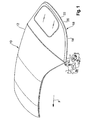
- Fig. 1 shows a perspective view of a hood 10 according to the invention for a convertible vehicle from behind.
- vehicle forward direction (vehicle direction) is indicated by an arrow F.
- the top has a top cloth or top cloth 12.
- the top 10 further has a clamping bracket 14.
- the clamping bracket 14 forms a receiving space 16 (FIG. Fig. 5 and 6 )
- a rear end 20 of the top material 12 seen in the vehicle direction is guided around the strip 18 and sewn thereto, as indicated by a seam 22.
- Fig. 2 shows a perspective view of the bar 18 according to the invention from behind.
- the bar 18 has two Strip sections 18a, 18b, which are manufactured separately.
- the one strip portion 18a of the bar 18 has a tapered region, on which the other strip portion 18b of the bar 18 is then inserted overlapping for the final production.
- a firm connection between the two strip portions 18a, 18b can be achieved by welding, gluing or the like.
- Fig. 3 is a perspective view of the bar 18 from the front, the bar 18 has a substantially rectangular cross-section. Furthermore, the bar 18 has a projection or projection 24, which extends in a longitudinal direction of the bar 18 in the receiving space 16 in the direction transverse to the insertion direction of the bar substantially.
- the strip 18 further has integral with it formed clips 28 and recesses 30.
- the strip 18 and the projection 24 are interrupted by the uniformly spaced recesses 30, wherein the clips 28 are arranged in the recesses 30.
- the clips 28 are deformable relative to adjacent strip parts, preferably elastically deformable.
- the clips 28 and the projection 24 are integrally formed with the strip 18, that is, in one piece and of the same material, for example made of plastic, reinforced plastic or the like.
- the recesses 30 interrupt the longitudinal extension of the strip 18 in a region 32 of the strip 18, which is the area which is intended to be introduced into the receiving space 16.
- the chips 28 serve as a holding device for the strip 18 when the strip 18 is attached to the clamping bracket 14, and have a certain flexibility, in particular with respect to adjacent strip parts, which is achieved, for example, that the clips 28 via a hinge with thinned Material with the remaining part the bar 18 are connected.
- the clips 28 are formed with a convex curvature or bend 34, wherein the curvature 34 is directed in substantially the same direction as the projection 24.
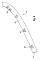
- the Fig. 4 shows a perspective view of the bar 18 from behind.
- the strip 18 has clips 36, one of which is shown and which are plugged onto the strip 18 or formed integrally therewith.
- the brackets 36 serve as an additional holding device in addition to the clips 28 for the bar 18 when the bar 18 is inserted into the receiving space 16 of the clamping bracket 14.
- the brackets 36 are provided such that they are located between the clips 28 located. In particular, the brackets 36 are placed on the bar 18 so that their legs can firmly clamp the bar 18.
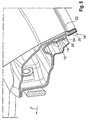
- Fig. 5 shows an enlarged sectional view through the clamping bracket 14, wherein the bar 18 is inserted into the receiving space 16 of the clamping bracket.
- the receiving space 16 is in the form of a longitudinal groove and extends substantially in a vehicle transverse direction.
- the projection 24 serves to define a relative position between the bar 18 and the clamping bracket 14. More specifically, the bar 18 can be inserted only up to its projection 24 in the receiving space 16, since this by abutting a wall 26 of the receiving space 16 another Insertion into the receiving space 16 prevented.
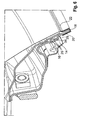
- Fig. 6 shows an enlarged sectional view through the clamping bracket 14, wherein the section through one of the clips 28 extends.
- the clips 28 are in the inserted state of the bar 18, the clips 28 in the receiving space 16.
- the clips 28 press with the curvature 34 and its free end walls 26 of the receiving space 16. This prevents the clips 28 that when the roof 10 is open or relaxed top material 12, the bar 18 can remove from the receiving space 16.
- the legs of the brackets 36 are pressed by the walls 26 of the receiving space 16 fixed to the bar 18.
- the brackets 36 support the clips 28 to hold the bar 18 in the receiving space 16.
- the bar For a change of the top fabric 12, for example, due to damage of the fabric can be pulled together with the brackets 36 from the receiving space 16 and thus from the clamping bracket 14 by a correspondingly light force with relaxed top material 12, the bar.
- the bracket is to be regarded as an optional, additional backup for the bar.
- the number of clamps can be determined as needed with respect to the respective clamp in which the strip is to be inserted.
- the bar can be formed in one piece or from more than two bar sections.
- the strip can be made of a material as needed and is not limited to plastic.
- a structure of the bar of any material that ensures the necessary stability of the bar and is sewable, is conceivable and not limited to the above types of plastic.
- Sheet metal or light metal, metal and alloys thereof for the strip are also possible. However, these materials are so far not sewable, so that the strip corresponding to prefabricated holes must be penetrated by a needle to be nourished.
- the sewing machine works with a given hole size, which corresponds to the spacing of the holes of the bar. Gluing the top fabric to the strip is also possible, but is not preferred due to the waiting time for curing or drying of the adhesive.
- the recess need not be evenly spaced. An arrangement of the recesses and the determination of their number are possible as needed.
- the walls of the receiving space have a shape complementary to the clip, ie also a curvature, into which the curvature of the clips when inserting the bar can latch, so that thus the holding effect is further enhanced.
- the number of clips can be determined as needed with regard to the respective clamping bracket, is to be introduced into the bar.
- the clips can be deformable only once upon insertion into the receiving space, ie deform plastically, so that they are to break off when removing the bar from the receiving space or otherwise destroyed.
- the rear portion of the top cloth, which is guided around the bar, may additionally be surrounded by a binding tape, which is sewn or screwed to the top and the bar.
Landscapes
- Engineering & Computer Science (AREA)
- Mechanical Engineering (AREA)
- Clamps And Clips (AREA)
- Vehicle Interior And Exterior Ornaments, Soundproofing, And Insulation (AREA)
- Connection Of Plates (AREA)
Abstract
Description
- Die Erfindung betrifft eine Leiste zum Anbringen von Verdeckstoff an einen Verdeckspannbügel und ein Verdeck mit einer Leiste.
- Die Verdeckgestängeteile eines Cabrioletfahrzeugs sind üblicherweise aus mehreren miteinander gelenkig verbundenen Bauteilen gebildet. Eines dieser Bauteile ist der sogenannte Verdeckspannbügel. Dieser ist in Fahrzeugrichtung gesehen der hinterste Teil des verdecks und spannt bei geschlossenem Verdeck den Verdeckstoff über einen Fahrgastinnenraum. Das in Fahrzeugvorwärtsfahrtrichtung (Fahrzeugrichtung) gesehen hinterste Ende des Verdeckstoffs wird üblicherweise an eine Kunststoffleiste angenäht. Diese Leiste wird mit dem angenähten Verdeckstoff von schräg hinten unten in einen Aufnahmeraum, der in dem Verdeckspannbügel gebildet ist, eingesteckt. Bei geschlossenem Verdeck wird die Leiste allein durch die Verdeckstoffspannung in den Spannbügel hineingezogen und so in ihrer Lage gesichert. Bei geöffnetem Verdeck besteht das Problem, dass die Leiste mit dem angenähtem Verdeckstoff keine Zugspannung erfährt und somit nicht mehr in den Aufnahmeraum hineingezogen wird. Um auch bei geöffnetem Verdeck und dementsprechend entspanntem Verdeckstoff die Leiste in ihrer Lage innerhalb des Spannbügels zu sichern, wurden verschiedene Vorrichtungen entwickelt.
- Die
EP 0 713 796 Bl offenbart ein Faltverdeck, bei dem ein Anzugsstreifen an einer Innenseite eines Verdeckbezugs bzw. eines Verdeckstoffs befestigt wird. Der Anzugsstreifen ist an seinem freien Ende mit einem federnden Spreizglied verbunden, das verrastend in eine Längsnut, die in dem Spannbügel gebildet ist, einsetzbar ist. Ein Schnapphaken des Spreizglieds hintergreift eine Nase der Längsnut. Das Spreizglied ist mit dem freien Ende des Anzugsstreifens vernäht oder verklebt. - Die
DE 41 12 256 C3 offenbart ein Klapp- bzw. Faltverdeck, bei dem ein Ende des Verdeckbezugs über eine hintere Kante des Spannbügels gezogen wird. Der Verdeckstoff wird mit Hilfe von Formleisten aus Kunststoff mit dem Spannbügel verschraubt. Dabei wird die Formleiste an den Verdeckstoff genäht. Ein Einfassband umschließt diesen Nahtbereich. - Eine Aufgabe der Erfindung ist es, eine Leiste anzugeben, mit der ein Verdeckstoff mit einem leichten Aufbau sicher an einen Spannbügel anbringbar ist.
- Diese Aufgabe wird durch eine Leiste gemäß Patentanspruch 1 und ein Verdeck gemäß Patentanspruch 11 gelöst. Weitere vorteilhafte Ausführungsformen der Erfindung sind in den abhängigen Ansprüchen angegeben.
- Der Erfindung liegt die Idee zugrunde, eine Leiste so integral mit einer Haltevorrichtung auszubilden, dass die Leiste einfach an einem Spannbügel angebracht werden kann. Einfach ist in diesem Zusammenhang so zu verstehen, dass es möglich ist, die Leiste an dem Spannbügel durch lediglich Einbringen der Haltevorrichtung in den Spannbügel anzubringen. Daher bedarf es keiner weiteren Bauteile zum Befestigen und die Leiste kann mit wenigen Arbeitsschritten befestigt werden. Berücksichtigt wurde dabei auch, dass eine Möglichkeit gegeben ist, die Leiste einfach herzustellen, indem die Leiste und die Haltevorrichtung gemeinsam, d.h. integral, durch beispielsweise bekannte Kunststoff formverfahren gefertigt werden können.
- Vorteilhafterweise weist eine Leiste zum Anbringen von Verdeckstoff bzw. -bezug an einen Spannbügel eines Verdecks eines Cabrioletfahrzeugs zumindest eine Haltevorrichtung auf, die integral mit der Leiste ausgebildet ist.
- Vorteilhafterweise ist die Haltevorrichtung ein Clip, wodurch eine einfache Herstellung gegeben ist.
- Vorteilhafterweise weist die Haltevorrichtung eine Wölbung auf und ist derart verformbar, dass sie sich in einem Zustand, in dem sie in einen in dem Verdeckspannbügel ausgebildeten Aufnahmeraum eingebracht ist, an eine Wand des Aufnahmeraums andrückt bzw, anpresst und so dafür sorgt, dass sich die Haltewirkung verstärkt und die Leiste, insbesondere bei geöffnetem Verdeck, besonders gut gehalten wird.
- Vorteilhafterweise sind mehrere Haltevorrichtungen vorgesehen und jede der Haltevorrichtungen ist in einer Ausnehmung der Leiste vorgesehen, wodurch die Gefahr, dass die Haltevorrichtung von der Leiste abbrechen kann, verringert ist.
- Vorteilhafterweise sind mehrere Haltevorrichtungen und mehrere Ausnehmungen vorgesehen, wobei die Ausnehmungen gleichmäßig voneinander beabstandet an der Leiste angeordnet sein könne, wodurch die Leiste sicher an mehreren Stellen in dem Aufnahmeraum gehalten werden kann.
- Vorteilhafterweise ist die Leiste zumindest teilweise in einen in dem Verdeckspannbügel ausgebildeten Aufnahmeraum einbringbar und weist zumindest eine Halteklammer als ein zusätzliches Sicherungsmittel oder entsprechendes herkömmliches Sicherungsmittel zum Halten der Leiste in dem Aufnahmeraum auf, wodurch eine zusätzliche Verstärkung der Haltewirkung erreicht wird. Allerdings sind solche Halteklammern bzw. Sicherungsmittel in weniger hoher Anzahl als bisher erforderlich.
- Vorteilhafterweise ist die Halteklammer derart an der Leiste vorgesehen, dass sie in einem Zustand, in dem die Leiste in dem Aufnahmeraum eingebracht ist, die Leiste mit ihren Schenkeln festhält, wodurch die Leiste besonders gut in dem Aufnahmeraum gehalten wird.
- Vorteilhafterweise ist ein Vorsprung an der Leiste vorgesehen, der sich in einer im Wesentlichen Längsrichtung der Leiste erstreckt, wodurch eine maximale Einbringtiefe der Leiste in den Spannbügel festlegbar ist.
- Vorteilhafterweise ist die Leiste aus wenigstens zwei Leistenabschnitten in Längsrichtung der Leiste gebildet, wodurch ermöglicht wird nur einzelne Teile der Leiste auszutauschen.
- Vorteilhafterweise ist die Leiste dazu angepasst, mit einem Verdeckstoff vernäht zu werden, so dass die Leiste schneller an einen Spannbügel eines Verdecks angebracht werden kann als bei einem Verkleben der Bauteile, da nicht abgewartet werden muss, bis das Klebemittel getrocknet bzw. ausgehärtet ist.
- Vorteilhafterweise weist ein Verdeck für ein Cabrioletfahrzeug einen Spannbügel auf, der einen Aufnahmeraum bildet, der zum Aufnehmen einer der vorstehend genannten Leisten angepasst ist, wodurch ein Verdeck angegeben ist, bei dem in einfacher Weise ein Verdeckstoff an einen Spannbügel angebracht werden kann. Dies wird besonders erleichtert, wenn der Verdeckstoff mit der Leiste vernäht ist.
- Weitere Merkmale und Zweckmäßigkeiten der Erfindung ergeben sich aus der Beschreibung einer beispielhaften Ausführungsform anhand der Figuren, von denen zeigen:
- Fig. 1
- eine perspektivische Ansicht eines Verdecks von hinten,
- Fig. 2
- eine perspektivische Ansicht einer Leiste von hinten,
- Fig. 3
- eine vergrößerte perspektivische Ansicht der Leiste von vorne
- Fig. 4
- eine vergrößerte perspektivische Ansicht der Leiste von hinten,
- Fig.5
- eine vergrößerte Schnittansicht durch einen Spannbügel mit angebrachtem Verdeckbezug, wobei der Schnitt nicht durch eine Haltevorrichtung der Leiste verläuft und
- Fig.6
- eine weitere vergrößerte Schnittansicht durch einen Spannbügel mit angebrachtem Verdeckbezug, wobei der Schnitt durch eine Haltevorrichtung der Leiste verläuft.
-
Fig. 1 zeigt eine perspektivische Ansicht eines erfindungsgemäßen Verdecks 10 für ein Cabrioletfahrzeug von hinten. Dabei ist die Fahrzeugvorwärtsfahrtrichtung (Fahrzeugrichtung) durch einen Pfeil F angegeben. Das Verdeck weist einen Verdeckbezug bzw. Verdeckstoff 12 auf. Das Verdeck 10 weist weiter einen Spannbügel 14 auf. Der Spannbügel 14 bildet einen Aufnahmeraum 16 (Fig. 5 und6 ) für eine Leiste 18. Ein in Fahrzeugrichtung gesehen hinteres Ende 20 des Verdeckstoffs 12 ist um die Leiste 18 herum geführt und mit dieser vernäht, wie durch eine Naht 22 angegeben ist. -
Fig. 2 zeigt eine perspektivische Ansicht der erfindungsgemäßen Leiste 18 von hinten. Die Leiste 18 weist zwei Leistenabschnitte 18a, 18b auf, die getrennt gefertigt werden. Dabei weist der eine Leistenabschnitt 18a der Leiste 18 einen sich verjüngenden Bereich auf, auf den der andere Leistenabschnitt 18b der Leiste 18 dann für die Endfertigung überlappend gesteckt wird. Eine feste Verbindung zwischen den beiden Leistenabschnitten 18a, 18b kann durch Schweißen, Kleben oder dergleichen erreicht werden. - Wie der
Fig. 3 zu entnehmen ist, die eine perspektivische Ansicht der Leiste 18 von vorne ist, weist die Leiste 18 einen im Wesentlichen quaderförmigen Querschnitt auf. Ferner weist die Leiste 18 einen Ansatz bzw. Vorsprung 24 auf, der sich im Wesentlichen in einer Längserstreckungsrichtung der Leiste 18 in Querrichtung zur Einschubrichtung der Leiste 18 in den Aufnahmeraum 16 erstreckt. - Die Leiste 18 weist weiter integral damit gebildete Clips 28 und Ausnehmungen 30 auf. Die Leiste 18 und der vorsprung 24 sind durch die voneinander gleichmäßig beabstandet angeordneten Ausnehmungen 30 unterbrochen, wobei die Clips 28 in den Ausnehmungen 30 angeordnet sind. Die Clips 28 sind relativ zu angrenzenden Leistenteilen verformbar, vorzugsweise elastisch verformbar. Die Clips 28 und der Vorsprung 24 sind integral mit der Leiste 18 ausgebildet, d.h. einstückig und materialeinheitlich, z.B. aus Kunststoff, verstärktem Kunststoff oder dergleichen. Die Ausnehmungen 30 unterbrechen die Längsstreckung der Leiste 18 dabei in einem Bereich 32 der Leiste 18, der der Bereich ist, der vorgesehen ist, in den Aufnahmeraum 16 eingebracht zu werden. Die Chips 28 dienen als Haltevorrichtung für die Leiste 18, wenn die Leiste 18 an dem Spannbügel 14 angebracht wird, und weisen eine gewisse Flexibilität, insbesondere gegenüber angrenzenden Leistenteilen, auf, die z.B. dadurch erreicht wird, dass die Clips 28 über ein Scharnier mit verdünntem Material mit dem restlichen Teil der Leiste 18 verbunden sind. Die Clips 28 sind mit einer konvexen Wölbung bzw. Biegung 34 ausgebildet, wobei die Wölbung 34 im Wesentlichen in die gleiche Richtung wie der Vorsprung 24 gerichtet ist.
- Die
Fig. 4 zeigt eine perspektivische Ansicht der Leiste 18 von hinten. Die Leiste 18 weist Klammern 36 auf, von denen eine gezeigt ist und die auf die Leiste 18 gesteckt sind oder integral mit dieser ausgebildet sind. Die Klammern 36 dienen als zusätzliche Haltevorrichtung neben den Clips 28 für die Leiste 18, wenn die Leiste 18 in den Aufnahmeraum 16 des Spannbügels 14 gesteckt wird. Die Klammern 36 sind derart vorgesehen, dass sie zwischen den Clips 28 befindlich angeordnet sind. Insbesondere sind die Klammern 36 so auf die Leiste 18 gesteckt, dass ihre Schenkel die Leiste 18 fest umklammern können. -
Fig. 5 zeigt eine vergrößerte Schnittansicht durch den Spannbügel 14, wobei die Leiste 18 in den Aufnahmeraum 16 des Spannbügels gesteckt ist. Der Aufnahmeraum 16 ist in der Form einer Längsnut und erstreckt sich im Wesentlichen in einer Fahrzeugquerrichtung. Der Vorsprung 24 dient dabei zum Definieren einer Relativlage zwischen der Leiste 18 und dem Spannbügel 14. Genauer gesagt kann die Leiste 18 nur bis zu ihrem vorsprung 24 in den Aufnahmeraum 16 eingesteckt werden, da dieser durch Anstoßen an eine Wand 26 des Aufnahmeraums 16 ein weiteres Einschieben in den Aufnahmeraum 16 verhindert. Bei geschlossenem Verdeck 10 wird durch die Spannung bzw. die Straffung des Verdeckstoffs 12 die Leiste 18 in den Aufnahmeraum 16 hineingezogen. Bei geöffnetem Verdeck kann sich die Leiste 18 aber auf Grund der nicht mehr vorhandenen Spannung durch den verdeckstoff 12 aus dem Aufnahmeraum 16 heraus bewegen. -
Fig. 6 zeigt eine vergrößerte Schnittansicht durch den Spannbügel 14, wobei der Schnitt durch einen der Clips 28 verläuft. Insbesondere befinden sich in dem eingesteckten Zustand der Leiste 18 die Clips 28 in dem Aufnahmeraum 16. Die Clips 28 drücken sich mit der Wölbung 34 und ihrem freien Ende an wände 26 des Aufnahmeraums 16. Dadurch verhindern die Clips 28, dass sich bei geöffneten Verdeck 10 bzw. entspanntem Verdeckstoff 12, die Leiste 18 aus dem Aufnahmeraum 16 entfernen kann. In diesem Zustand, in dem die Leiste 18 in den Aufnahmeraum 16 gesteckt ist, werden die Schenkel der Klammern 36 durch die Wände 26 des Aufnahmeraums 16 fest an die Leiste 18 gedrückt. Dadurch unterstützen die Klammern 36 die Clips 28, die Leiste 18 in dem Aufnahmeraum 16 zu halten. - Für ein Wechseln des Verdeckstoffs 12, beispielsweise aufgrund einer Beschädigung des Stoffs, kann durch eine entsprechend leichte Krafteinwirkung bei entspanntem Verdeckstoff 12 die Leiste 18 zusammen mit den Klammern 36 aus dem Aufnahmeraum 16 und damit aus dem Spannbügel 14 gezogen werden.
- Ist es erforderlich die Leiste 18 zu wechseln, beispielsweise auf Grund einer Beschädigung der Leiste 18, ist es lediglich erforderlich, die Naht 22 aufzutrennen. Da der Verdeckstoff 12 nicht mit der Leiste 18 verklebt ist, müssen bei einem Wechsel der Leiste 18 auch keine Klebstoffreste entfernt werden.
- Die Klammer ist als optionale, zusätzliche Sicherung für die Leiste anzusehen. Die Anzahl der Klammern kann nach Bedarf im Hinblick auf den jeweiligen Spannbügel, in den die Leiste eingebracht werden soll, festgelegt werden.
- Die Leiste kann einstückig oder aus mehr als zwei Leistenabschnitten gebildet werden. Die Leiste kann aus einem Material nach Bedarf gefertigt sein und ist nicht auf Kunststoff eingeschränkt. Ein Aufbau der Leiste aus jedem Material, das die nötige Stabilität der Leiste gewährleistet und nähbar ist, ist denkbar und nicht auf die oben angegebenen Kunststoffarten beschränkt. Blech oder Leichtmetall, Metall und Legierungen davon für die Leiste sind ebenso möglich. Allerdings sind diese Materialien bislang nicht nähbar, so dass die Leiste entsprechend vorgefertigte Löcher aufweisen muss, die von einer Nadel zum vernähren durchdrungen werden. Die Nähmaschine arbeitet dabei mit einer vorgegeben Lochweite, die den Abständen der Löcher der Leiste entspricht. Auch ein Verkleben des Verdeckstoffs mit der Leiste ist möglich, ist aber auf Grund der Wartezeit für das Aushärten bzw. Trocknen des Klebemittels nicht bevorzugt.
- Die Ausnehmung müssen nicht gleichmäßig beabstandet angeordnet sein. Ein Anordnen der Ausnehmungen und die Festlegung ihrer Anzahl sind nach Bedarf möglich.
- Denkbar ist auch, dass die Wände des Aufnahmeraums eine dem Clip komplementäre Form, d.h. auch eine Wölbung, aufweisen, in die die Wölbung der Clips beim Einstecken der Leiste verrasten können, so dass damit die Haltewirkung noch weiter verstärkt wird. Die Zahl der Clips kann nach Bedarf im Hinblick auf den jeweiligen Spannbügel, in die Leiste eingebracht werden soll, festgelegt werden. Die Clips können nur einmal beim Einbringen in den Aufnahmeraum verformbar sein, d.h. sich plastisch verformen, so dass sie bei einem Entfernen der Leiste aus dem Aufnahmeraum abbrechen oder anderweitig zu zerstören sind.
- Der hintere Bereich des Verdeckstoffs, der um die Leiste geführt ist, kann zusätzlich von einem Einfassband umgeben sein, das mit dem Verdeckstöff und der Leiste vernäht oder verschraubt wird.
Claims (12)
- Leiste (18) zum Anbringen von Verdeckstoff (12) an einen Spannbügel (14) eines Verdecks (10) eines Cabrioletfahrzeugs, wobei die Leiste zumindest eine Haltevorrichtung (28) aufweist, die integral mit der Leiste ausgebildet ist.
- Leiste (18) nach Anspruch 1, bei der die Haltevorrichtung (28) ein Clip (28) ist.
- Leiste (18) nach Anspruch 2, bei der die Haltevorrichtung (28) eine Wölbung (34) aufweist und derart verformbar ist, dass sie sich in einem Zustand, in dem sie in einen in dem Verdeckspannbügel (14) ausgebildeten Aufnahmeraum (16) eingebracht ist, an eine Wand (26) des Aufnahmeraums (16) andrückt.
- Leiste (18) nach einem der vorhergehenden Ansprüche, bei der mehrere Haltevorrichtungen (28) vorgesehen sind und jede der Haltevorrichtungen (28) in einer Ausnehmung (30) der Leiste (18) vorgesehen ist.
- Leiste (18) nach Anspruch 4, bei der mehrere Haltevorrichtungen (28) und mehrere Ausnehmungen (30) vorgesehen sind, wobei die Ausnehmungen (30) gleichmäßig voneinander beabstandet an der Leiste (18) angeordnet sind.
- Leiste (18) nach einem der vorhergehenden Ansprüche, wobei die Leiste (18) zumindest teilweise in einen in dem Verdeckspannbügel (14) ausgebildeten Aufnahmeraum (16) einbringbar ist, und die zumindest eine Halteklammer (36) als ein zusätzliches Sicherungsmittel zum Halten der Leiste (18) in dem Aufnahmeraum (16) aufweist.
- Leiste (18) nach Anspruch 6, bei der die Halteklammer (36) derart an der Leiste (18) vorgesehen ist, dass sie in einem zustand, in dem die Leiste (18) in dem Aufnahmeraum (16) eingebracht ist, die Leiste (18) mit ihren Schenkeln festhält.
- Leiste (18) nach einem der vorhergehenden Ansprüche, bei der ein Vorsprung (24) vorgesehen ist, der sich in einer im Wesentlichen Längsrichtung der Leiste (18) erstreckt.
- Leiste (18) nach einem der vorhergehenden Ansprüche, die aus wenigstens zwei Leistenabschnitten (18a, 18b) in Längsrichtung der Leiste (18) gebildet ist.
- Leiste (18) nach einem der vorhergehenden Ansprüche, die dazu angepasst ist, mit einem Verdeckstoff (12) vernäht zu werden.
- Verdeck (10) für ein Cabrioletfahrzeug, das einen Spannbügel (14) aufweist, wobei der Spannbügel (14) einen Aufnahmeraum (16) bildet, der zum Aufnehmen einer Leiste (18) nach einem der vorhergehenden Ansprüche angepasst ist.
- Verdeck (10) nach Anspruch 11, mit einem Verdeckstoff (12), der mit der Leiste (18) vernäht ist.
Applications Claiming Priority (1)
| Application Number | Priority Date | Filing Date | Title |
|---|---|---|---|
| DE102008013894A DE102008013894A1 (de) | 2008-03-12 | 2008-03-12 | Leiste zum Anbringen von Verdeckstoff an einen Verdeckspannbügel und Verdeck mit einer Leiste |
Publications (3)
| Publication Number | Publication Date |
|---|---|
| EP2100760A2 true EP2100760A2 (de) | 2009-09-16 |
| EP2100760A3 EP2100760A3 (de) | 2014-12-10 |
| EP2100760B1 EP2100760B1 (de) | 2018-08-22 |
Family
ID=40756697
Family Applications (1)
| Application Number | Title | Priority Date | Filing Date |
|---|---|---|---|
| EP09003068.5A Ceased EP2100760B1 (de) | 2008-03-12 | 2009-03-04 | Leiste zum Anbringen von Verdeckstoff an einen Verdeckspannbügel und Verdeck mit einer Leiste |
Country Status (2)
| Country | Link |
|---|---|
| EP (1) | EP2100760B1 (de) |
| DE (1) | DE102008013894A1 (de) |
Citations (2)
| Publication number | Priority date | Publication date | Assignee | Title |
|---|---|---|---|---|
| DE4112256C2 (de) | 1991-04-15 | 1993-10-14 | Parat Werk Schoenenbach Gmbh | Klapp- bzw. Faltverdeck für Fahrzeuge wie Cabriolets o. dgl. |
| EP0713796B1 (de) | 1994-11-23 | 1998-08-19 | Dr.Ing.h.c. F. Porsche Aktiengesellschaft | Faltverdeck für Fahrzeuge |
Family Cites Families (9)
| Publication number | Priority date | Publication date | Assignee | Title |
|---|---|---|---|---|
| DE9102147U1 (de) * | 1991-02-23 | 1991-05-16 | Wilhelm Karmann GmbH, 4500 Osnabrück | Haltevorrichtung für das Verdeck eines Cabriolet-Fahrzeuges |
| US5702147A (en) * | 1995-05-09 | 1997-12-30 | Bestop, Inc. | Tailgate sealing arrangement |
| JP2003512216A (ja) * | 1999-03-18 | 2003-04-02 | デューラ コンバーティブル システムズ,インコーポレイティド | 幌のタックストリップ及びその取り付け方法 |
| CN1308178C (zh) * | 2000-12-23 | 2007-04-04 | 宝马公司 | 汽车车身外壳的平坦部分 |
| DE10224095B4 (de) * | 2002-05-31 | 2010-07-15 | Bayerische Motoren Werke Aktiengesellschaft | Verdeckstoffbefestigung für ein Cabriolet |
| DE10240213B4 (de) * | 2002-08-28 | 2005-03-24 | Open Air Systems Gmbh | Verdeck eines Fahrzeugs mit einem Dachteil sowie Dachmodul mit einem derartigen Verdeck |
| DE10331407B3 (de) * | 2003-07-10 | 2004-12-23 | Open Air Systems Gmbh | Spriegel für ein Faltverdeck |
| DE102004016201B4 (de) * | 2004-04-01 | 2006-05-11 | Wilhelm Karmann Gmbh | Verdeck eines Cabriolet-Kraftfahrzeuges |
| DE102006036658B3 (de) * | 2006-08-05 | 2008-01-10 | Magna Car Top Systems Gmbh | Spannbügel für ein Fahrzeugdach, vorzugsweise für Kraftfahrzeuge |
-
2008
- 2008-03-12 DE DE102008013894A patent/DE102008013894A1/de not_active Withdrawn
-
2009
- 2009-03-04 EP EP09003068.5A patent/EP2100760B1/de not_active Ceased
Patent Citations (2)
| Publication number | Priority date | Publication date | Assignee | Title |
|---|---|---|---|---|
| DE4112256C2 (de) | 1991-04-15 | 1993-10-14 | Parat Werk Schoenenbach Gmbh | Klapp- bzw. Faltverdeck für Fahrzeuge wie Cabriolets o. dgl. |
| EP0713796B1 (de) | 1994-11-23 | 1998-08-19 | Dr.Ing.h.c. F. Porsche Aktiengesellschaft | Faltverdeck für Fahrzeuge |
Also Published As
| Publication number | Publication date |
|---|---|
| EP2100760B1 (de) | 2018-08-22 |
| DE102008013894A1 (de) | 2009-09-17 |
| EP2100760A3 (de) | 2014-12-10 |
Similar Documents
| Publication | Publication Date | Title |
|---|---|---|
| DE60131785T2 (de) | Zubehörbefestigungssystem für fahrzeuginnenräume | |
| EP2004430B1 (de) | Rolloanordnung für ein fahrzeug | |
| DE102007055016B3 (de) | Verkleidungsteil mit Airbagabdeckung und Verfahren zum Herstellen eines Verkleidungsteils | |
| DE3902278C1 (de) | ||
| DE3918802A1 (de) | Schmutzfaengerbefestigung | |
| DE202014003512U1 (de) | Befestigungsvorrichtung sowie Gassackmodul | |
| DE10042087B4 (de) | Befestigungssystem für einen Kraftfahrzeugkotflügel und eine Klammer dafür | |
| DE112016006808B4 (de) | Bezugsstoff-befestigungsklemme | |
| DE60122086T2 (de) | Fahrzeugsitzbezug | |
| DE2907656C2 (de) | ||
| DE69008132T2 (de) | Vorrichtung zum Befestigen eines Überzuges eines Kraftzeugsitzes. | |
| EP2100760B1 (de) | Leiste zum Anbringen von Verdeckstoff an einen Verdeckspannbügel und Verdeck mit einer Leiste | |
| DE10106738C2 (de) | Vorrichtung zum Festlegen einer Heckscheibe an einem Bezug eines Cabrioletverdecks | |
| DE10335220B4 (de) | Anbindungsvorrichtung eines Fahrzeughimmels an einen Rahmen eines Schiebedachs eines Kraftfahrzeuges | |
| DE60031617T2 (de) | Anordnung zur Befestigung eines Einbauelementes in einer Öffnung einer Trägerplatte | |
| DE2701350A1 (de) | Verbindervorrichtung | |
| EP1273739B1 (de) | Vorrichtung zum Manipulieren von Lasten, insbesondere von Stahlmatten aus Stahlstäben | |
| DE102008024894B4 (de) | Befestigungsanordnung | |
| DE29801871U1 (de) | Gassack-Modul für einen Kopfschutz-Gassack | |
| EP1445526A1 (de) | Fixierteil für eine Schlauchschelle | |
| DE29804548U1 (de) | Dichtungsprofil für ein Kraftfahrzeug | |
| DE60036910T2 (de) | Rollo mit Gehäuse und Halteelementen | |
| DE19916542C1 (de) | Befestigungsvorrichtung für einen Bezug eines Fahrzeugsitzes | |
| DE102015009367A1 (de) | Befestiger zum lösbaren Verbinden eines Paneels an einer Struktur, Abdeckpaneel für ein Airbag und Fahrzeug mit einer Struktur und einem Airbag | |
| DE102016111091B3 (de) | Halterung für das Kennzeichen eines Fahrzeugs |
Legal Events
| Date | Code | Title | Description |
|---|---|---|---|
| PUAI | Public reference made under article 153(3) epc to a published international application that has entered the european phase |
Free format text: ORIGINAL CODE: 0009012 |
|
| AK | Designated contracting states |
Kind code of ref document: A2 Designated state(s): AT BE BG CH CY CZ DE DK EE ES FI FR GB GR HR HU IE IS IT LI LT LU LV MC MK MT NL NO PL PT RO SE SI SK TR |
|
| AX | Request for extension of the european patent |
Extension state: AL BA RS |
|
| 19U | Interruption of proceedings before grant |
Effective date: 20090629 |
|
| 19W | Proceedings resumed before grant after interruption of proceedings |
Effective date: 20101201 |
|
| RAP1 | Party data changed (applicant data changed or rights of an application transferred) |
Owner name: VALMET AUTOMOTIVE OY |
|
| PUAL | Search report despatched |
Free format text: ORIGINAL CODE: 0009013 |
|
| AK | Designated contracting states |
Kind code of ref document: A3 Designated state(s): AT BE BG CH CY CZ DE DK EE ES FI FR GB GR HR HU IE IS IT LI LT LU LV MC MK MT NL NO PL PT RO SE SI SK TR |
|
| AX | Request for extension of the european patent |
Extension state: AL BA RS |
|
| RIC1 | Information provided on ipc code assigned before grant |
Ipc: B60J 7/12 20060101AFI20141104BHEP |
|
| 17P | Request for examination filed |
Effective date: 20150511 |
|
| RBV | Designated contracting states (corrected) |
Designated state(s): AT BE BG CH CY CZ DE DK EE ES FI FR GB GR HR HU IE IS IT LI LT LU LV MC MK MT NL NO PL PT RO SE SI SK TR |
|
| RBV | Designated contracting states (corrected) |
Designated state(s): AT BE BG CH CY CZ DE DK EE ES FI FR GB GR HR HU IE IS IT LI LT LU LV MC MK MT NL NO PL PT RO SE SI SK TR |
|
| AKX | Designation fees paid |
Designated state(s): DE FR GB |
|
| AXX | Extension fees paid |
Extension state: AL Extension state: BA Extension state: RS |
|
| GRAP | Despatch of communication of intention to grant a patent |
Free format text: ORIGINAL CODE: EPIDOSNIGR1 |
|
| INTG | Intention to grant announced |
Effective date: 20180305 |
|
| GRAS | Grant fee paid |
Free format text: ORIGINAL CODE: EPIDOSNIGR3 |
|
| GRAA | (expected) grant |
Free format text: ORIGINAL CODE: 0009210 |
|
| RIN1 | Information on inventor provided before grant (corrected) |
Inventor name: KREILING, NILS |
|
| AK | Designated contracting states |
Kind code of ref document: B1 Designated state(s): DE FR GB |
|
| REG | Reference to a national code |
Ref country code: GB Ref legal event code: FG4D Free format text: NOT ENGLISH |
|
| REG | Reference to a national code |
Ref country code: DE Ref legal event code: R096 Ref document number: 502009015202 Country of ref document: DE |
|
| REG | Reference to a national code |
Ref country code: DE Ref legal event code: R097 Ref document number: 502009015202 Country of ref document: DE |
|
| PLBE | No opposition filed within time limit |
Free format text: ORIGINAL CODE: 0009261 |
|
| STAA | Information on the status of an ep patent application or granted ep patent |
Free format text: STATUS: NO OPPOSITION FILED WITHIN TIME LIMIT |
|
| 26N | No opposition filed |
Effective date: 20190523 |
|
| PGFP | Annual fee paid to national office [announced via postgrant information from national office to epo] |
Ref country code: GB Payment date: 20220324 Year of fee payment: 14 |
|
| PGFP | Annual fee paid to national office [announced via postgrant information from national office to epo] |
Ref country code: FR Payment date: 20220322 Year of fee payment: 14 |
|
| P01 | Opt-out of the competence of the unified patent court (upc) registered |
Effective date: 20230601 |
|
| PGFP | Annual fee paid to national office [announced via postgrant information from national office to epo] |
Ref country code: DE Payment date: 20230519 Year of fee payment: 15 |
|
| GBPC | Gb: european patent ceased through non-payment of renewal fee |
Effective date: 20230304 |
|
| PG25 | Lapsed in a contracting state [announced via postgrant information from national office to epo] |
Ref country code: GB Free format text: LAPSE BECAUSE OF NON-PAYMENT OF DUE FEES Effective date: 20230304 |
|
| PG25 | Lapsed in a contracting state [announced via postgrant information from national office to epo] |
Ref country code: GB Free format text: LAPSE BECAUSE OF NON-PAYMENT OF DUE FEES Effective date: 20230304 Ref country code: FR Free format text: LAPSE BECAUSE OF NON-PAYMENT OF DUE FEES Effective date: 20230331 |
|
| REG | Reference to a national code |
Ref country code: DE Ref legal event code: R119 Ref document number: 502009015202 Country of ref document: DE |
|
| PG25 | Lapsed in a contracting state [announced via postgrant information from national office to epo] |
Ref country code: DE Free format text: LAPSE BECAUSE OF NON-PAYMENT OF DUE FEES Effective date: 20241001 |
|
| PG25 | Lapsed in a contracting state [announced via postgrant information from national office to epo] |
Ref country code: DE Free format text: LAPSE BECAUSE OF NON-PAYMENT OF DUE FEES Effective date: 20241001 |