EP2100541B1 - Elementary support for an object display comprising an articulated polyhedral case - Google Patents
Elementary support for an object display comprising an articulated polyhedral case Download PDFInfo
- Publication number
- EP2100541B1 EP2100541B1 EP20090290173 EP09290173A EP2100541B1 EP 2100541 B1 EP2100541 B1 EP 2100541B1 EP 20090290173 EP20090290173 EP 20090290173 EP 09290173 A EP09290173 A EP 09290173A EP 2100541 B1 EP2100541 B1 EP 2100541B1
- Authority
- EP
- European Patent Office
- Prior art keywords
- box
- holding
- sleeve
- support
- edges
- Prior art date
- Legal status (The legal status is an assumption and is not a legal conclusion. Google has not performed a legal analysis and makes no representation as to the accuracy of the status listed.)
- Active
Links
- 238000004026 adhesive bonding Methods 0.000 description 2
- 238000005452 bending Methods 0.000 description 2
- 238000012423 maintenance Methods 0.000 description 2
- 230000000007 visual effect Effects 0.000 description 1
Images


Classifications
-
- G—PHYSICS
- G06—COMPUTING; CALCULATING OR COUNTING
- G06F—ELECTRIC DIGITAL DATA PROCESSING
- G06F1/00—Details not covered by groups G06F3/00 - G06F13/00 and G06F21/00
- G06F1/16—Constructional details or arrangements
-
- A—HUMAN NECESSITIES
- A47—FURNITURE; DOMESTIC ARTICLES OR APPLIANCES; COFFEE MILLS; SPICE MILLS; SUCTION CLEANERS IN GENERAL
- A47F—SPECIAL FURNITURE, FITTINGS, OR ACCESSORIES FOR SHOPS, STOREHOUSES, BARS, RESTAURANTS OR THE LIKE; PAYING COUNTERS
- A47F3/00—Show cases or show cabinets
- A47F3/14—Display trays or containers
-
- A—HUMAN NECESSITIES
- A47—FURNITURE; DOMESTIC ARTICLES OR APPLIANCES; COFFEE MILLS; SPICE MILLS; SUCTION CLEANERS IN GENERAL
- A47F—SPECIAL FURNITURE, FITTINGS, OR ACCESSORIES FOR SHOPS, STOREHOUSES, BARS, RESTAURANTS OR THE LIKE; PAYING COUNTERS
- A47F5/00—Show stands, hangers, or shelves characterised by their constructional features
- A47F5/10—Adjustable or foldable or dismountable display stands
- A47F5/11—Adjustable or foldable or dismountable display stands made of cardboard, paper or the like
- A47F5/112—Adjustable or foldable or dismountable display stands made of cardboard, paper or the like hand-folded from sheet material
-
- G—PHYSICS
- G06—COMPUTING; CALCULATING OR COUNTING
- G06F—ELECTRIC DIGITAL DATA PROCESSING
- G06F1/00—Details not covered by groups G06F3/00 - G06F13/00 and G06F21/00
- G06F1/16—Constructional details or arrangements
- G06F1/1601—Constructional details related to the housing of computer displays, e.g. of CRT monitors, of flat displays
-
- G—PHYSICS
- G09—EDUCATION; CRYPTOGRAPHY; DISPLAY; ADVERTISING; SEALS
- G09F—DISPLAYING; ADVERTISING; SIGNS; LABELS OR NAME-PLATES; SEALS
- G09F1/00—Cardboard or like show-cards of foldable or flexible material
- G09F1/04—Folded cards
- G09F1/06—Folded cards to be erected in three dimensions
-
- G—PHYSICS
- G09—EDUCATION; CRYPTOGRAPHY; DISPLAY; ADVERTISING; SEALS
- G09F—DISPLAYING; ADVERTISING; SIGNS; LABELS OR NAME-PLATES; SEALS
- G09F15/00—Boards, hoardings, pillars, or like structures for notices, placards, posters, or the like
- G09F15/0006—Boards, hoardings, pillars, or like structures for notices, placards, posters, or the like planar structures comprising one or more panels
- G09F15/0056—Boards, hoardings, pillars, or like structures for notices, placards, posters, or the like planar structures comprising one or more panels portable display standards
- G09F15/0062—Boards, hoardings, pillars, or like structures for notices, placards, posters, or the like planar structures comprising one or more panels portable display standards collapsible
Definitions
- the field of the invention is that of displays foldable on themselves and unfolded almost automatically, with the advantage of being able to be transported and stored under excellent conditions, on the one hand, and to be quickly installed on site, on the other hand.
- Such displays can be used for communication or visual advertising at points of sale, called POS, and be in the form of a column.
- POS points of sale
- Such displays are described in the document FR 2,824,946 .
- an elementary object display carrier comprising a hinged polyhedric case for moving between a folded flat state and an unfolded and open functional state for receiving an object, retractable means for holding the box in its unfolded and open state, and resilient biasing means of the holding means in the non-retracted holding position, the flattening of the box being effected by retraction of the holding means against the action of the elastic means.
- a polyhedron is a flat-faced body.
- the box of the prior document does not support a body or any object of significant weight.
- the invention of the present application relates first of all to an elementary support of the type defined above, characterized in that the box comprises a polyhedral sleeve with hinge edges and at least one retractable wall for pivoting support. , the hinge edges delimiting a floor face and a ceiling face of the box and the retractable pivoting holding wall being arranged to ensure, between these ceiling and floor faces, a shoring function.
- the holding wall is a retractable shoring wall.
- the box can easily support on the ceiling surface a body or any object of significant weight, or even another elementary support and even a plurality of these supports.
- the holding wall is pivotally mounted around an orthogonal edge at the hinge and outer edges of the polyhedral sleeve.
- the holding wall is pivotally mounted around an inner edge of the sleeve.
- the support box comprises a single compartment, in the other embodiments, it may comprise two.
- the holding wall is pivotally mounted around an edge parallel to the hinge edges.
- the holding wall may be hollowed out as the faces of the box which are parallel to it in the folded and unfolded states of the box.
- the invention also relates to a set of several elementary supports as defined above.
- FIG. 1 a first embodiment of the elementary display rack of the invention.
- This is a polyhedral box 1, in this case parallelepipedic, with a sleeve 2 with four faces 3-6 joined by their common edges 7-10 constituting articulation edges.
- the sleeve 2 On one side, the sleeve 2 is almost open, with only two small flaps 11, 12 hinged around two edges 13, 14 of the two opposite faces 6.4 of the box 1, the edges 13, 14 being perpendicular and orthogonal to the articulation edges 7-10.
- the sleeve 2 can be closed by two retractable flaps 15, 16 for maintaining the box 1 in an unfolded and open state, as will now be explained.
- the two holding flaps 15, 16 are pivotally mounted around the two ridges 17, 18 opposite faces 6.4 to the edges 13, 14 of articulation of the two small front flaps 11, 12.
- the sum of their widths is substantially equal to the width of the sleeve 2 in the open state, that is to say the width of both floor 5 and ceiling 3 faces of the sleeve 2.
- Notches are formed from the three free edges 19, 20, 21 and 22, 23, 24 of the two holding flaps 15, 16 as well as from the two rear edges 25, 26 of the faces 3, 5, notches terminated by eyelets. receipt of a return elastic 27.
- the elastic 27 is passed through a pair of eyelets 28 of the face 3, near the edge 25, a pair eyelets 29 of the flap 15, near its edge 20, a pair of eyelets 30 of the face 5, near the edge 26, and a pair of eyelets 31 of the flap 16, near its edge 23.
- the box 1 can evolve between a folded flat state and a functional state unfolded and open to receive an object in its single compartment.
- the faces of the sleeve 2 are two by two on one another 3, 4 and 5, 6 after pivoting around the four hinge edges 7-10.
- the sleeve is held in the open state by the holding flaps 15, 16 pivoted around the outer edges 17, 18, orthogonal to the hinge edges, under the action of the elastic 27, which arranged the four pairs of eyelets 28-31 substantially, in a common plane to reduce its tension, the edges 19, 21 and 22, 24 of the two flaps 15, 16 coming substantially in the plane of the two edges 25, 26 to serve as a support for both sides 3, 5.
- the two flaps are then in the non-retracted holding position and provide a shoring function between the floor face 5 and the ceiling face 3.
- the flattening of the box 1 is effected by retracting the flaps 15, 16, that is to say by rotating them around their edges 17, 18, against the action of the elastic return 27, and by folding against the inside of the faces 6, 4.
- box 1 which has just been described may be stacked or juxtaposed on top of each other or next to each other, by any appropriate fastening means, for example by gluing.
- Element 100 shown above the other 150 on the figure 3 -
- the two elements differs only by the fixing of the return elastic - is also a box parallelepiped 101, with a sleeve 102 four-sided 103-106 joined by their common edges 107-110 constituting hinge edges.
- a retractable holding wall 115 is pivotally mounted about a central line 116 of the face 105, a line extending orthogonally to the hinge edges of the box and substantially equal distances from the anterior edges 111, 112 and posterior 113, 114 of the box, edges perpendicular to the hinge edges of the box and belonging to the upper faces 103 and lower 105 of the box.
- the holding wall is rectangular and corresponds to the opening section of the sleeve 102, of width equal to the length of the edges 111-114 and of height equal to the length of the edges 117-120 connecting the hinge edges 107-110 .
- Notches are formed from the anterior edge 111 of the face 103 of the box and from the free edge 121 of the holding wall 115, opposite its pivoting edge 116, notches ending with eyelets receiving a return elastic 127.
- the elastic is passed through a pair of eyelets 128 of the face 103, near the edge 111, and in a pair of eyelets 129 of the holding wall 115, near its free edge 121.
- a pair of eyelets 128 of the face 103 near the edge 111
- a pair of eyelets 129 of the holding wall 115 near its free edge 121.
- the box 100 can evolve between a folded flat state and a functional state unfolded and open to receive one or more objects.
- the box In the functional state, the box has two compartments 130, 131, one on each side of the holding wall 115.
- the faces of the sleeve 102 are in pairs on one another 103, 104 and 105, 106, after pivoting around the four hinge edges 107-110.
- the sleeve is held in the open state by the holding wall 115 pivoted around its edge 116, orthogonal to the hinge edges, under the action of the elastic 127 which has brought the two together. pairs of eyelets 128, 129, the holding wall substantially in a plane perpendicular to the four faces 103-106 of the sleeve 102 of the box 100, which it serves as a support. The wall 115 is then in the non-retracted position of maintaining the box 100 in the open position.
- the flattening of the box 101 of the sleeve 102 is effected by retracting the wall 115, that is to say by rotating it around its hinge edge 116 and pushing it and bending it against the face 105, bringing its free edge 121 closer to the posterior edge 114 of this lower face 105.
- the other element 150 is fixed to the element 100, here by gluing. It is distinguished from the associated element 100 by the fixing of the return elastic 157 and the reversal of the pivoting of the holding wall.
- the lower face 155 of the sleeve of the box 150 as indeed, the upper face 103 of the box 100, has a central opening 158.
- the Elastic 157 is here passed outside the box, through the central opening 158.
- pivoting edges of the two walls 115 and 160 of the two boxes 100 and 150 are opposite, one at the bottom, on the figure 3 on the lower face 105, the other, at the top, on the upper face of the box 150 here coincides with the underside of the associated box.
- the wall of maintenance 115 can not ensure its function of shoring between these two faces ceiling and floor. Therefore, it is preferable to use the box 100, and therefore the box 150, in a position rotated by 90 ° with respect to that illustrated in FIG. figure 3 , so that the holding wall 115, even if it is not perfectly pivoted, still ensures its shoring function between the faces, no longer 103 and 105, but between the faces 104 and 106, perpendicular to the faces 103 and 105. In this case, the holding wall 115, in the non-retracted position, will always form with these faces 104, 106 a force descent to serve as a support for a body of significant weight.
- the elementary support always comprises a parallelepipedic polyhedral box 201, with a sleeve 202 with four faces 203-206 joined by four outer articulation edges 207-210.
- the two upper 203 and lower 205 faces can be folded in two along two inner bending, articulation and pivot edges 211, 212, parallel to the outer hinge edges.
- a retractable wall 221 substantially of the same dimensions as the lateral faces 204, 206 of the sleeve 202, is pivotally mounted around the lower pivoting edge 212 of the lower face 205 of the sleeve 202.
- Notches are formed in the upper face 203 of the sleeve 202, on either side of the fold line 211 of the face 203 of the sleeve 202, and from the edges 213, 214 of the face 203, perpendicular to the edges 207, 210, notches which end with eyelets 215-218 for receiving return elastics 219, 220.
- Notches are also provided in the retractable wall 221, from its two edges 222 orthogonal to the hinge edges 207-210, near of the pivoting edge 212, and which end with eyelets 223 for receiving the return elastics 219-220.
- the retractable wall 221, as the side faces 204, 206 of the sleeve 202 are recessed 224, 225.
- retractable walls 230-232 are provided, pivotally mounted around the four outer edges 226-229 of the sleeve 222, orthogonal to the hinge edges 207-210.
- the box 201 can evolve between a folded flat state and a functional state unfolded and open to receive one or more objects.
- the box comprises two compartments 233, 234, one on each side of the retractable wall 221, in the non-retracted, raised and holding position of the upper faces 203 and lower 205, along the lines 211, 212, with which the face retractable wall forms a descent of force to serve as a support for a body of significant weight.
- the squaring of the box 201 is performed by folding the secondary retaining walls 230-232 against the lateral faces of the sleeve and, against the action of the return elastics 219-, 220, by pivoting the median holding wall 221 around its pivoting edge 212.
- the two faces 203, 205 fold in two along the lines 211, 212, the two lateral faces 204, 206 coming against each other with interposition of the free upper part of the median holding wall 221.
Description
Le domaine de l'invention est celui des présentoirs repliables sur eux-mêmes et dépliables quasi-automatiquement, avec, pour avantage, de pouvoir être transportés et stockés dans d'excellentes conditions, d'une part, et d'être rapidement installés sur site, d'autre part.The field of the invention is that of displays foldable on themselves and unfolded almost automatically, with the advantage of being able to be transported and stored under excellent conditions, on the one hand, and to be quickly installed on site, on the other hand.
A partir d'un état replié, il suffit de commencer à déplier le support pour que, sous l'action de moyens élastiques de rappel, il se déplie complètement automatiquement.From a folded state, simply begin to unfold the support so that, under the action of resilient return means, it unfolds completely automatically.
Naturellement, à l'inverse, le repliement du support s'effectue contre l'action des moyens de rappel.Naturally, conversely, the folding of the support takes place against the action of the return means.
Le demandeur développe de tels présentoirs depuis longtemps.The applicant has been developing such displays for a long time.
Il avait commencé par des présentoirs supports d'informations. De tels présentoirs peuvent servir à la communication ou publicité visuelle sur les lieux de vente, dite PLV, et se présenter sous forme de colonne. De tels présentoirs sont décrits dans le document
Puis, le demandeur a proposé des présentoirs supports dont l'espace intérieur, dans l'état déployé, est laissé libre pour pouvoir y glisser un objet ou glisser le support autour d'un objet, qui dépasse ou non du support. Ces présentoirs sont décrits dans la demande de brevet français
Le demandeur avait d'ailleurs auparavant déjà proposé des colonnes supports d'informations pour PLV permettant aussi de recevoir des objets, comme celles décrites dans le document
Et bien aujourd'hui, le demandeur propose des présentoirs réalisés sur un principe similaire, mais destinés tout d'abord à supporter ou présenter des objets et, accessoirement, des informations.Well today, the applicant offers displays made on a similar principle, but intended primarily to support or present objects and, incidentally, information.
On connaît déjà, par le document
On rappellera qu'un polyèdre est un corps à faces planes.It will be recalled that a polyhedron is a flat-faced body.
La case du document antérieur ne permet toutefois pas de supporter un corps ou tout objet d'un poids important.The box of the prior document, however, does not support a body or any object of significant weight.
Ainsi, l'invention de la présente demande concerne tout d'abord un support élémentaire du type défini ci-dessus, caractérisé par le fait que la case comporte un manchon polyédrique avec des arêtes d'articulation et au moins une paroi escamotable de maintien pivotante, les arêtes d'articulation délimitant une face plancher et une face plafond de la case et la paroi escamotable de maintien pivotante étant agencée pour assurer, entre ces faces plafond et plancher, une fonction d'étaiement.Thus, the invention of the present application relates first of all to an elementary support of the type defined above, characterized in that the box comprises a polyhedral sleeve with hinge edges and at least one retractable wall for pivoting support. , the hinge edges delimiting a floor face and a ceiling face of the box and the retractable pivoting holding wall being arranged to ensure, between these ceiling and floor faces, a shoring function.
La paroi de maintien est une paroi d'étaiement escamotable.The holding wall is a retractable shoring wall.
Dans ces conditions, la case peut facilement supporter sur la surface plafond un corps ou tout objet d'un poids important, voire un autre support élémentaire et même une pluralité de ces supports.Under these conditions, the box can easily support on the ceiling surface a body or any object of significant weight, or even another elementary support and even a plurality of these supports.
En d'autres termes, à l'état déplié et ouvert de la case, la face plafond et la paroi d'étaiement forment, jusqu'au sol, une descente de force.In other words, in the unfolded and open state of the box, the ceiling face and the shoring wall form, to the ground, a descent force.
Dans une première forme de réalisation, la paroi de maintien est montée pivotante autour d'une arête orthogonale aux arêtes d'articulation et extérieure du manchon polyédrique.In a first embodiment, the holding wall is pivotally mounted around an orthogonal edge at the hinge and outer edges of the polyhedral sleeve.
Dans d'autres formes de réalisation, la paroi de maintien est montée pivotante autour d'une arête intérieure au manchon.In other embodiments, the holding wall is pivotally mounted around an inner edge of the sleeve.
Dans la première forme de réalisation, la case support comporte un unique compartiment, dans les autres formes de réalisation, elle peut en comporter deux.In the first embodiment, the support box comprises a single compartment, in the other embodiments, it may comprise two.
Dans une forme de réalisation particulière, la paroi de maintien est montée pivotante autour d'une arête parallèle aux arêtes d'articulation.In a particular embodiment, the holding wall is pivotally mounted around an edge parallel to the hinge edges.
Dans ce cas, la paroi de maintien est peut-être évidée comme les faces de la case qui lui sont parallèles dans les états repliés et dépliés de la case.In this case, the holding wall may be hollowed out as the faces of the box which are parallel to it in the folded and unfolded states of the box.
Toujours dans ce cas, on peut prévoir des parois de maintien secondaires montées librement pivotantes autour d'arêtes extérieures du manchon polyédrique.Still in this case, it is possible to provide secondary holding walls mounted freely pivoting around outer edges of the polyhedral sleeve.
L'invention concerne également un ensemble de plusieurs supports élémentaires tels que définis ci-dessus.The invention also relates to a set of several elementary supports as defined above.
L'invention sera mieux comprise à l'aide de la description suivante de plusieurs formes de réalisation du support élémentaire et de l'ensemble de supports élémentaires de l'invention, en référence au dessin en annexe, sur lequel
- la
figure 1 est une vue en perspective de face d'une première forme de réalisation du support élémentaire de présentoir ; - la
figure 2 est une vue en perspective arrière du support de lafigure 1 ; - la
figure 3 est une vue en perspective de face d'un ensemble de deux secondes formes de réalisation du support élémentaire de présentoir et - la
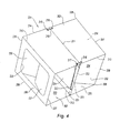
figure 4 est une vue en perspective d'une troisième forme de réalisation du support élémentaire de présentoir de l'invention.
- the
figure 1 is a front perspective view of a first embodiment of the elementary display stand; - the
figure 2 is a rear perspective view of the support of thefigure 1 ; - the
figure 3 is a front perspective view of a set of two second embodiments of the display stand elementary support and - the
figure 4 is a perspective view of a third embodiment of the elementary display rack of the invention.
En référence aux
D'un côté, le manchon 2 est quasiment ouvert, avec seulement deux petits rabats 11, 12 articulés autour de deux arêtes 13, 14 des deux faces opposées 6,4 de la case 1, les arêtes 13, 14 étant perpendiculaires et orthogonales aux arêtes d'articulation 7-10. De l'autre côté, le manchon 2 peut être fermé par deux rabats escamotables 15, 16 de maintien de la case 1 dans un état déplié et ouvert, comme cela va maintenant être expliqué.On one side, the
Les deux rabats de maintien 15, 16 sont montés pivotants autour des deux arêtes 17, 18 des faces 6,4 opposées aux arêtes 13, 14 d'articulation des deux petits rabats antérieurs 11, 12. La somme de leurs largeurs est sensiblement égale à la largeur du manchon 2 à l'état ouvert, c'est-à-dire à la largeur des deux faces plancher 5 et plafond 3 du manchon 2.The two
Des échancrures sont ménagées depuis les trois bords libres 19, 20, 21 et 22, 23, 24 des deux rabats de maintien 15, 16 ainsi que depuis les deux bords arrières 25, 26 des faces 3, 5, échancrures terminées par des oeillets de réception d'un élastique de rappel 27. Ainsi, l'élastique 27 est passé dans une paire d'oeillets 28 de la face 3, près du bord 25, une paire d'oeillets 29 du rabat 15, près de son bord 20, une paire d'oeillets 30 de la face 5, près du bord 26, et une paire d'oeillets 31 du rabat 16, près de son bord 23.Notches are formed from the three
Ainsi, la case 1 peut évoluer entre un état replié à plat et un état fonctionnel déplié et ouvert pour recevoir un objet dans son unique compartiment. A plat, les faces du manchon 2 sont deux à deux l'une sur l'autre 3, 4 et 5, 6 après pivotement autour des quatre arêtes d'articulation 7-10. Le manchon est maintenu à l'état ouvert par les rabats de maintien 15, 16 pivotés autour des arêtes extérieures 17, 18, orthogonales aux arêtes d'articulation, sous l'action de l'élastique 27, qui a disposé les quatre paires d'oeillets 28-31 sensiblement, dans un plan commun pour diminuer sa tension, les bords 19, 21 et 22, 24 des deux rabats 15, 16 venant sensiblement dans le plan des deux bords 25, 26 pour servir d'appui aux deux faces 3, 5. Les deux rabats sont alors en position non escamotée de maintien et assurent une fonction d'étaiement entre la face plancher 5 et la face plafond 3.Thus, the box 1 can evolve between a folded flat state and a functional state unfolded and open to receive an object in its single compartment. Flat, the faces of the
La mise à plat de la case 1 (du manchon 2) s'effectue en escamotant les rabats 15, 16, c'est-à-dire en les faisant pivoter autour de leurs arêtes 17, 18, contre l'action de l'élastique de rappel 27, et en les rabattant contre l'intérieur des faces 6, 4.The flattening of the box 1 (of the sleeve 2) is effected by retracting the
Naturellement, une pluralité de cases comme la case 1 qui vient d'être décrite peuvent être empilées ou juxtaposées les unes sur les autres ou à côté des autres, par tout moyen de fixation approprié, par exemple par collage.Naturally, a plurality of boxes such as box 1 which has just been described may be stacked or juxtaposed on top of each other or next to each other, by any appropriate fastening means, for example by gluing.
En référence à la
Une paroi de maintien escamotable 115 est montée pivotante autour d'une ligne centrale 116 de la face 105, ligne s'étendant orthogonalement aux arêtes d'articulation de la case et sensiblement à égales distances des bords antérieurs 111, 112 et postérieurs 113, 114 de la case, bords perpendiculaires aux arêtes d'articulation de la case et appartenant aux faces supérieure 103 et inférieure 105 de la case. La paroi de maintien est rectangulaire et correspond à la section d'ouverture du manchon 102, de largeur égale à la longueur des bords 111-114 et de hauteur égale à la longueur des arêtes 117-120 reliant les arêtes d'articulation 107-110.A
Des échancrures sont ménagées depuis le bord antérieur 111 de la face 103 de la case et depuis le bord libre 121 de la paroi de maintien 115, opposé à son bord de pivotement 116, échancrures terminées par des oeillets de réception d'un élastique de rappel 127.Notches are formed from the
Ainsi, l'élastique est passé dans une paire d'oeillets 128 de la face 103, près du bord 111, et dans une paire d'oeillets 129 de la paroi de maintien 115, près de son bord libre 121. L'élastique s'étend ici directement de l'une des deux paires d'oeillets 128, 129 à l'autre.Thus, the elastic is passed through a pair of
Ainsi, la case 100 peut évoluer entre un état replié à plat et un état fonctionnel déplié et ouvert pour recevoir un ou plusieurs objets. A l'état fonctionnel, la case comporte deux compartiments 130, 131, un de chaque côté de la paroi de maintien 115.Thus, the
A plat, les faces du manchon 102 sont deux à deux l'une sur l'autre 103, 104 et 105, 106, après pivotement autour des quatre arêtes d'articulation 107-110.Flat, the faces of the
Le manchon est maintenu à l'état ouvert par la paroi de maintien 115 pivotée autour de son arête 116, orthogonale aux arêtes d'articulation, sous l'action de l'élastique 127 qui a rapproché l'une de l'autre les deux paires d'oeillets 128, 129, la paroi de maintien venant sensiblement dans un plan perpendiculaire aux quatre faces 103-106 du manchon 102 de la case 100, auxquelles elle sert d'appui. La paroi 115 est alors en position non escamotée de maintien de la case 100 en position ouverte.The sleeve is held in the open state by the
La mise à plat de la case 101 du manchon 102 s'effectue en escamotant la paroi 115, c'est-à-dire en la faisant pivoter autour de son arête d'articulation 116 et en la poussant et en la rabattant contre la face inférieure 105, en rapprochant son bord libre 121 du bord postérieur 114 de cette face inférieure 105.The flattening of the
L'autre élément 150 est fixé à l'élément 100, ici par collage. Il se distingue de l'élément associé 100 par la fixation de l'élastique de rappel 157 et l'inversion du pivotement de la paroi de maintien. La face inférieure 155 du manchon de la case 150, tout comme d'ailleurs, la face supérieure 103 de la case 100, comporte une ouverture centrale 158. Et bien au lieu de tendre l'élastique 157 entre la paire d'oeillets 159 du bord libre 161 de la paroi de maintien escamotable 160, d'une part, et la paire d'oeillets du bord postérieur inférieur de la face inférieure 155, d'autre part, par l'intérieur de la case, comme précédemment, l'élastique 157 est ici passé à l'extérieur de la case, à travers l'ouverture centrale 158.The
On notera que les arêtes de pivotement des deux parois 115 et 160 des deux cases 100 et 150 sont opposées, l'une en bas, sur la
On remarquera, en référence à la
En référence à la
Les deux faces supérieure 203 et inférieure 205 peuvent être pliées en deux le long de deux arêtes de pliage, d'articulation et de pivotement intérieures 211, 212, parallèles aux arêtes d'articulation extérieures.The two upper 203 and lower 205 faces can be folded in two along two inner bending, articulation and pivot
Une paroi escamotable 221, sensiblement de mêmes dimensions que les faces latérales 204, 206 du manchon 202, est montée pivotante autour de l'arête inférieure de pivotement 212 de la face inférieure 205 du manchon 202.A
Des échancrures sont ménagées dans la face supérieure 203 du manchon 202, de part et d'autre de la ligne de pliage 211 de la face 203 du manchon 202, et depuis les bords 213, 214 de la face 203, perpendiculaires aux arêtes 207, 210, échancrures qui se terminent par des oeillets 215-218 de réception d'élastiques de rappel 219, 220. Des échancrures sont également ménagées dans la paroi escamotables 221, depuis ses deux bords 222 orthogonaux aux arêtes d'articulation 207-210, près de l'arête de pivotement 212, et qui se terminent par des oeillets 223 de réception des élastiques de rappel 219-220.Notches are formed in the
Dans la forme de réalisation de la
Quatre autres parois escamotables 230-232 sont prévues, montées pivotantes autour des quatre arêtes extérieures 226-229 du manchon 222, orthogonales aux arêtes d'articulation 207-210.Four other retractable walls 230-232 are provided, pivotally mounted around the four outer edges 226-229 of the
Ainsi, la case 201 peut évoluer entre un état replié à plat et un état fonctionnel déplié et ouvert pour recevoir un ou plusieurs objets.Thus, the
A l'état fonctionnel (
Cette position relevée de la paroi médiane 221 a été atteinte sous l'action des élastiques de rappel 219, 220. Pour parfaire le maintien du manchon 202 dans sa forme parallélépipédique, on a fait pivoter les parois de maintien secondaires 230-232 autour de leurs arêtes de pivotement, depuis leur positions plaquées contre les faces latérales 206, 204 jusque dans leur position de maintien des faces supérieure 203 et inférieure 205, sensiblement orthogonales aux faces 203-206 du manchon 202.This raised position of the
La mise à plat de la case 201 s'effectue en rabattant les parois de maintien secondaires 230-232 contre les faces latérales du manchon et, contre l'action des élastiques de rappel 219-, 220, en faisant pivoter la paroi de maintien médiane 221 autour de son arête de pivotement 212. Lors de cette mise à plat, les deux faces 203, 205 se plient en deux le long des lignes 211, 212, les deux faces latérales 204, 206 venant l'une contre l'autre avec interposition de la partie supérieure libre de la paroi de maintien médiane 221.The squaring of the
Claims (10)
- Elementary support for an object display, comprising a polyhedral box (1; 101; 201) articulated to switch between a flat folded state and a functional unfolded state in which it is open to receive an object, retractable means (15, 16; 115; 221) for holding the box in its unfolded, open state, and resilient means (27; 127; 219; 220) for biasing the holding means in the non-retracted holding position, the flattening of the box being carried out by retracting the holding means counter to the action of the resilient means, characterised in that the box comprises a polyhedral sleeve (2; 102; 202), with articulation edges (7-10; 107-110; 207-210) and at least one pivoting retractable holding wall (15, 16; 115, 221), the pivoting retractable holding wall (15, 16; 115, 221) being a shoring wall between a floor surface (5; 105; 205) and a ceiling surface (3; 103; 203) with which it produces a downward application of force.
- Support according to claim 1, wherein the retractable holding wall (15, 16; 115) is arranged to pivot about an edge (17, 18; 116) orthogonal to the articulation edges of the sleeve.
- Support according to one of claims 1 and 2, wherein the holding wall (11, 12) is mounted to be pivotable about an outer edge (13, 14) of the polyhedral sleeve.
- Support according to one of claims 1 and 2, wherein the holding wall (115; 221) is mounted to be pivotable about an edge (116; 212) inside the sleeve (102; 202).
- Support according to one of claims 1 to 3, wherein the support box (1) comprises a single compartment.
- Support according to one of claims 1, 2 and 4, wherein the support box (101; 201) comprises two compartments (130, 131; 233, 234).
- Support according to one of claims 1, 4 and 6, wherein the holding wall (221) is mounted to be pivotable about an edge (212) parallel to the articulation edges.
- Support according to claim 7, wherein the holding wall (221) is recessed like the surfaces (204, 206) of the box (201) that are parallel thereto in the folded and unfolded states of the box.
- Support according to claim 8, wherein secondary holding walls (230-232) are provided which are mounted to be freely pivotable about outer edges (226-229) of the polyhedral sleeve (202).
- Set of several elementary supports (1; 100, 150; 201) according to one of claims 1 to 9.
Priority Applications (1)
| Application Number | Priority Date | Filing Date | Title |
|---|---|---|---|
| PL09290173T PL2100541T3 (en) | 2008-03-12 | 2009-03-11 | Elementary support for an object display comprising an articulated polyhedral case |
Applications Claiming Priority (1)
| Application Number | Priority Date | Filing Date | Title |
|---|---|---|---|
| FR0801347A FR2928528B1 (en) | 2008-03-12 | 2008-03-12 | ELEMENTARY OBJECT DISPENSER SUPPORT COMPRISING AN ARTICULATED POLYEDRIQUE CASE. |
Publications (2)
| Publication Number | Publication Date |
|---|---|
| EP2100541A1 EP2100541A1 (en) | 2009-09-16 |
| EP2100541B1 true EP2100541B1 (en) | 2015-05-06 |
Family
ID=39831862
Family Applications (1)
| Application Number | Title | Priority Date | Filing Date |
|---|---|---|---|
| EP20090290173 Active EP2100541B1 (en) | 2008-03-12 | 2009-03-11 | Elementary support for an object display comprising an articulated polyhedral case |
Country Status (37)
| Country | Link |
|---|---|
| US (1) | US8348360B2 (en) |
| EP (1) | EP2100541B1 (en) |
| JP (1) | JP5339596B2 (en) |
| KR (1) | KR101352202B1 (en) |
| CN (1) | CN101530275B (en) |
| AP (1) | AP2566A (en) |
| AR (1) | AR071746A1 (en) |
| AT (1) | AT506442B1 (en) |
| AU (1) | AU2009200790B2 (en) |
| BE (1) | BE1018920A3 (en) |
| BR (1) | BRPI0900651B1 (en) |
| CA (1) | CA2655597C (en) |
| CH (1) | CH698631B1 (en) |
| CL (1) | CL2009000520A1 (en) |
| CO (1) | CO6200100A1 (en) |
| DE (1) | DE102009001060A1 (en) |
| EG (1) | EG26486A (en) |
| ES (2) | ES2353511B8 (en) |
| FR (1) | FR2928528B1 (en) |
| GB (1) | GB2458343B (en) |
| GR (1) | GR1008222B (en) |
| IS (1) | IS2953B (en) |
| IT (1) | IT1393435B1 (en) |
| LU (1) | LU91536B1 (en) |
| MA (1) | MA30851B1 (en) |
| ME (1) | MEP8709A (en) |
| MX (1) | MX2009002755A (en) |
| NZ (1) | NZ575230A (en) |
| PE (1) | PE20100043A1 (en) |
| PL (1) | PL2100541T3 (en) |
| PT (1) | PT104422B (en) |
| RO (1) | RO125741B1 (en) |
| RU (1) | RU2500326C2 (en) |
| SG (1) | SG155855A1 (en) |
| TW (1) | TWI562637B (en) |
| UA (1) | UA95491C2 (en) |
| ZA (1) | ZA200901472B (en) |
Families Citing this family (6)
| Publication number | Priority date | Publication date | Assignee | Title |
|---|---|---|---|---|
| FR2955472B1 (en) | 2010-01-27 | 2012-01-20 | Hotel Francois L | OBJECT PRESENTATION BRACKET |
| KR101213494B1 (en) * | 2010-05-12 | 2012-12-20 | 삼성디스플레이 주식회사 | A solid display apparatus, a flexible display apparatus, and a method for manufacturing the display apparatuses |
| ES2537350B1 (en) | 2013-07-04 | 2016-03-15 | Ferrán Mestres Armengol | Self-expanding folding hollow body for exhibitor and self-expanding folding hollow structural assembly for exhibitor |
| CN107301823A (en) * | 2017-06-15 | 2017-10-27 | 洪海光电集团有限公司 | Lift multimedia presentation device |
| CN110861821B (en) * | 2017-06-26 | 2021-09-03 | 上海鸿研物流技术有限公司 | Logistics appliance and empty and full state identification method thereof |
| CN111627356A (en) * | 2020-06-17 | 2020-09-04 | 龙岩市康庆科技有限公司 | Environmental protection and energy saving technique is with show board |
Family Cites Families (40)
| Publication number | Priority date | Publication date | Assignee | Title |
|---|---|---|---|---|
| US1216071A (en) * | 1916-08-09 | 1917-02-13 | Alfred H Carstensen | Hat-box. |
| FR702817A (en) | 1929-11-01 | 1931-04-17 | Kali Forschungsanstalt Gmbh | Improvements to processes for obtaining calcium or magnesium orthophosphates |
| US1871706A (en) * | 1931-04-03 | 1932-08-16 | William R Krebs | Foldable paper box |
| GB467854A (en) * | 1936-01-24 | 1937-06-24 | William Augustus May | Improvements in or relating to advertising circulars, showcards or the like |
| US3010246A (en) * | 1959-04-20 | 1961-11-28 | England Press Inc | Self-forming device |
| FR1254983A (en) * | 1960-01-16 | 1961-03-03 | Thibaud & Cie G | Foldable display |
| US3300166A (en) * | 1965-06-14 | 1967-01-24 | Container Corp | Collapsible automatically set up display container |
| US3385424A (en) * | 1966-04-11 | 1968-05-28 | Robertshaw Controls Co | Carton and insert |
| US3391848A (en) * | 1967-01-13 | 1968-07-09 | Martin L. Schmidt | Pop-open box |
| US3576354A (en) * | 1969-05-08 | 1971-04-27 | Roseth Corp | Knockdown closets |
| DE6936641U (en) * | 1969-09-17 | 1970-01-02 | Stabernack Gmbh Gustav | SALES DISPLAY |
| GB1381135A (en) * | 1972-09-29 | 1975-01-22 | Tonhaeuser H L | Display device |
| CA975961A (en) * | 1972-12-18 | 1975-10-14 | David C. Jenkins | Self-erecting devices |
| US3933300A (en) * | 1975-01-20 | 1976-01-20 | Hoerner Waldorf Corporation | Loin box with locking cover |
| US3987957A (en) * | 1975-10-31 | 1976-10-26 | Container Corporation Of America | One piece simplex carton |
| US4335830A (en) * | 1980-11-17 | 1982-06-22 | Industrial Packaging Co., Inc. | Solution container |
| US4619426A (en) * | 1985-05-22 | 1986-10-28 | Drueck Jr Fred | Self-erecting hollow structure |
| IL77611A (en) * | 1986-01-15 | 1988-11-15 | Abraham Schnapp | Toy comprising an expandable cube |
| US4854060A (en) * | 1987-02-27 | 1989-08-08 | Manco Inc. | Self-erecting photo display |
| US4723664A (en) * | 1987-03-26 | 1988-02-09 | Arrow Art Finishers Co. | Reinforced display stand for supporting heavy loads |
| JP2511770Y2 (en) * | 1990-06-07 | 1996-09-25 | レンゴー株式会社 | Display stand |
| DE4102082A1 (en) * | 1991-01-24 | 1992-07-30 | Horst Gmbh & Co Kg | Goods-carrier of carton form or formed of cardboard paper - has foot with dies joined by elastic tension pieces, and fold lines |
| JP3662328B2 (en) * | 1996-01-29 | 2005-06-22 | 株式会社Tana−X | Structure that lifts and holds the inner box |
| US5887782A (en) * | 1997-09-24 | 1999-03-30 | Mueller; Charles J. | High stacking strength automatic corrugated box |
| CN2364771Y (en) * | 1998-01-26 | 2000-02-23 | 汤玛士·贝尔斯 | Photo connection and picture show frame |
| AU2000265752A1 (en) * | 2000-07-11 | 2001-10-23 | Francois L'hotel | Folding structure for displaying information |
| JP2002308349A (en) * | 2001-04-11 | 2002-10-23 | Shinsei:Kk | Thermal insulating box |
| FR2824946B1 (en) | 2001-05-18 | 2003-10-03 | Hotel Francois L | INFORMATION DISPLAY HOLDER HAVING AT LEAST ONE FACE OF PRESENTATION |
| JP4049623B2 (en) * | 2002-06-26 | 2008-02-20 | レンゴー株式会社 | Two-stage display stand |
| US20040111930A1 (en) * | 2002-09-17 | 2004-06-17 | Ossmann Francis J. | Advertising/promotional display system with integral sound generating means |
| FR2847062B1 (en) | 2002-11-12 | 2005-01-07 | Hotel Francois L | INFORMATION HOLDER HOLDER HOLDER |
| CA2435134C (en) * | 2003-07-10 | 2013-02-05 | Geoffrey A. Moss | Display stand with foldable self erecting supporting base |
| GB0317928D0 (en) * | 2003-07-31 | 2003-09-03 | Atomic Mk Ltd | Display device |
| JP2005132407A (en) * | 2003-10-30 | 2005-05-26 | Kyocera Mita Corp | Carton box |
| JP2005343478A (en) * | 2004-05-31 | 2005-12-15 | Sharp Corp | Packaging box |
| FR2876827B1 (en) * | 2004-10-06 | 2007-04-27 | L'hotel Francois | INSERT HOLDER HOLDER WITH DISCRETE ACTION INSERTS |
| JP3993191B2 (en) * | 2004-10-19 | 2007-10-17 | 日本通運株式会社 | Foldable container |
| AU2006213811B8 (en) * | 2005-02-11 | 2010-07-01 | Graphic Packaging International, Inc. | Carton with interlocking divider |
| RU54904U1 (en) * | 2005-09-19 | 2006-07-27 | Общество с ограниченной ответственностью "Конкорд-М" | SURPRISE PACKAGING |
| FR2915305B1 (en) | 2007-04-18 | 2009-06-05 | Hotel Francois L | INVISIBLE FIXING MOUNT DISPLAY STAND |
-
2008
- 2008-03-12 FR FR0801347A patent/FR2928528B1/en active Active
-
2009
- 2009-02-20 DE DE102009001060A patent/DE102009001060A1/en not_active Ceased
- 2009-02-23 CH CH00267/09A patent/CH698631B1/en not_active IP Right Cessation
- 2009-02-23 CA CA2655597A patent/CA2655597C/en active Active
- 2009-02-26 GR GR20090100116A patent/GR1008222B/en active IP Right Grant
- 2009-02-27 NZ NZ575230A patent/NZ575230A/en not_active IP Right Cessation
- 2009-02-27 AU AU2009200790A patent/AU2009200790B2/en not_active Ceased
- 2009-03-01 EG EG2009030280A patent/EG26486A/en active
- 2009-03-02 RO ROA200900193A patent/RO125741B1/en unknown
- 2009-03-02 RU RU2009107284/12A patent/RU2500326C2/en active
- 2009-03-02 ZA ZA2009/01472A patent/ZA200901472B/en unknown
- 2009-03-03 TW TW098106778A patent/TWI562637B/en not_active IP Right Cessation
- 2009-03-03 PT PT104422A patent/PT104422B/en active IP Right Grant
- 2009-03-04 GB GB0903735A patent/GB2458343B/en active Active
- 2009-03-05 CL CL2009000520A patent/CL2009000520A1/en unknown
- 2009-03-05 MA MA31688A patent/MA30851B1/en unknown
- 2009-03-06 AR ARP090100821A patent/AR071746A1/en active IP Right Grant
- 2009-03-06 AP AP2009004797A patent/AP2566A/en active
- 2009-03-06 JP JP2009053511A patent/JP5339596B2/en not_active Expired - Fee Related
- 2009-03-06 ES ES200900626A patent/ES2353511B8/en active Active
- 2009-03-06 LU LU91536A patent/LU91536B1/en active
- 2009-03-09 IS IS8805A patent/IS2953B/en unknown
- 2009-03-09 ME MEP-87/09A patent/MEP8709A/en unknown
- 2009-03-09 CO CO09023942A patent/CO6200100A1/en active IP Right Grant
- 2009-03-10 PE PE2009000350A patent/PE20100043A1/en active IP Right Grant
- 2009-03-10 BR BRPI0900651-6 patent/BRPI0900651B1/en not_active IP Right Cessation
- 2009-03-10 SG SG200901812-8A patent/SG155855A1/en unknown
- 2009-03-10 IT ITTO2009A000175A patent/IT1393435B1/en active
- 2009-03-10 AT ATA387/2009A patent/AT506442B1/en not_active IP Right Cessation
- 2009-03-11 UA UAA200902137A patent/UA95491C2/en unknown
- 2009-03-11 KR KR1020090020549A patent/KR101352202B1/en active IP Right Grant
- 2009-03-11 ES ES09290173.5T patent/ES2544487T3/en active Active
- 2009-03-11 EP EP20090290173 patent/EP2100541B1/en active Active
- 2009-03-11 PL PL09290173T patent/PL2100541T3/en unknown
- 2009-03-12 BE BE2009/0144A patent/BE1018920A3/en not_active IP Right Cessation
- 2009-03-12 US US12/402,654 patent/US8348360B2/en active Active
- 2009-03-12 MX MX2009002755A patent/MX2009002755A/en active IP Right Grant
- 2009-03-12 CN CN200910130784.9A patent/CN101530275B/en not_active Expired - Fee Related
Also Published As
Similar Documents
| Publication | Publication Date | Title |
|---|---|---|
| EP1804621B1 (en) | Very simple information presentation support and methods for assembly and disassembly of said support | |
| EP2528482B1 (en) | Item display stand | |
| EP2100541B1 (en) | Elementary support for an object display comprising an articulated polyhedral case | |
| CA2581924C (en) | Information display support | |
| EP1983498B1 (en) | Display stand support with invisible attachment flaps | |
| EP2526839B1 (en) | Display pack which can be collapsed flat and which expands automatically | |
| EP0575275B1 (en) | Foldable display unit structure, entirely made from cardboard | |
| FR2876827A1 (en) | Information display support for communication, has inserts equal in length to distance between side edges of panel, and elastic bands co-operating with inserts and flaps and exerting opposite vertical forces to maintain inserts heightwise | |
| EP2028113B1 (en) | Banana transport tray comprising seats supporting a top tray which can be easily shaped, associated shaping method | |
| FR2812526A1 (en) | System for building cardboard stand for displaying articles for sale comprises shelves made up of polygonal base and peripheral wall and with slots in their corners through which polygonal tubes which lock together to form a rack | |
| FR3117753A1 (en) | Display structure comprising foldable tray support elements | |
| EP1596350A1 (en) | Self erecting display stand | |
| FR3017526A1 (en) | MERCHANDISE PRESENTATION CARRIER FOR VEHICLE AND EQUIPPED VEHICLE | |
| FR3116368A1 (en) | Collapsible device for presenting visual information | |
| FR2957055A1 (en) | Assembly for arranging e.g. goods in displaying and transporting box, has subunits articulated around folding lines between position in extension of one another and deployed position in which subunits are juxtaposed against one another | |
| FR2841218A1 (en) | Cardboard cake box with handle comprises body and hinged lid, body formed by raising lateral walls which cause lifting of rear and front walls, flap locking deployed body enables forming of handle from pre-cuts | |
| FR2727384A1 (en) | Container used for transporting, storage and display of poultry | |
| EP1783057A1 (en) | Package with flaps, made of semi-rigid material, for the packaging and sales display of articles. |
Legal Events
| Date | Code | Title | Description |
|---|---|---|---|
| PUAI | Public reference made under article 153(3) epc to a published international application that has entered the european phase |
Free format text: ORIGINAL CODE: 0009012 |
|
| AK | Designated contracting states |
Kind code of ref document: A1 Designated state(s): AT BE BG CH CY CZ DE DK EE ES FI FR GB GR HR HU IE IS IT LI LT LU LV MC MK MT NL NO PL PT RO SE SI SK TR |
|
| AX | Request for extension of the european patent |
Extension state: AL BA RS |
|
| 17P | Request for examination filed |
Effective date: 20100310 |
|
| 17Q | First examination report despatched |
Effective date: 20100409 |
|
| AKX | Designation fees paid |
Designated state(s): AT BE BG CH CY CZ DE DK EE ES FI FR GB GR HR HU IE IS IT LI LT LU LV MC MK MT NL NO PL PT RO SE SI SK TR |
|
| AXX | Extension fees paid |
Extension state: RS Payment date: 20090404 Extension state: BA Payment date: 20090404 |
|
| GRAP | Despatch of communication of intention to grant a patent |
Free format text: ORIGINAL CODE: EPIDOSNIGR1 |
|
| INTG | Intention to grant announced |
Effective date: 20141029 |
|
| RAP1 | Party data changed (applicant data changed or rights of an application transferred) |
Owner name: L'HOTEL, FRANCOIS |
|
| RIN1 | Information on inventor provided before grant (corrected) |
Inventor name: L'HOTEL, FRANCOIS |
|
| GRAS | Grant fee paid |
Free format text: ORIGINAL CODE: EPIDOSNIGR3 |
|
| GRAA | (expected) grant |
Free format text: ORIGINAL CODE: 0009210 |
|
| AK | Designated contracting states |
Kind code of ref document: B1 Designated state(s): AT BE BG CH CY CZ DE DK EE ES FI FR GB GR HR HU IE IS IT LI LT LU LV MC MK MT NL NO PL PT RO SE SI SK TR |
|
| AX | Request for extension of the european patent |
Extension state: BA RS |
|
| REG | Reference to a national code |
Ref country code: GB Ref legal event code: FG4D Free format text: NOT ENGLISH |
|
| REG | Reference to a national code |
Ref country code: CH Ref legal event code: EP |
|
| REG | Reference to a national code |
Ref country code: IE Ref legal event code: FG4D Free format text: LANGUAGE OF EP DOCUMENT: FRENCH |
|
| REG | Reference to a national code |
Ref country code: AT Ref legal event code: REF Ref document number: 725104 Country of ref document: AT Kind code of ref document: T Effective date: 20150615 |
|
| REG | Reference to a national code |
Ref country code: DE Ref legal event code: R096 Ref document number: 602009031061 Country of ref document: DE Effective date: 20150618 |
|
| REG | Reference to a national code |
Ref country code: NL Ref legal event code: T3 |
|
| REG | Reference to a national code |
Ref country code: SE Ref legal event code: TRGR |
|
| REG | Reference to a national code |
Ref country code: ES Ref legal event code: FG2A Ref document number: 2544487 Country of ref document: ES Kind code of ref document: T3 Effective date: 20150831 |
|
| REG | Reference to a national code |
Ref country code: AT Ref legal event code: MK05 Ref document number: 725104 Country of ref document: AT Kind code of ref document: T Effective date: 20150506 |
|
| REG | Reference to a national code |
Ref country code: LT Ref legal event code: MG4D |
|
| PG25 | Lapsed in a contracting state [announced via postgrant information from national office to epo] |
Ref country code: HR Free format text: LAPSE BECAUSE OF FAILURE TO SUBMIT A TRANSLATION OF THE DESCRIPTION OR TO PAY THE FEE WITHIN THE PRESCRIBED TIME-LIMIT Effective date: 20150506 Ref country code: LT Free format text: LAPSE BECAUSE OF FAILURE TO SUBMIT A TRANSLATION OF THE DESCRIPTION OR TO PAY THE FEE WITHIN THE PRESCRIBED TIME-LIMIT Effective date: 20150506 Ref country code: FI Free format text: LAPSE BECAUSE OF FAILURE TO SUBMIT A TRANSLATION OF THE DESCRIPTION OR TO PAY THE FEE WITHIN THE PRESCRIBED TIME-LIMIT Effective date: 20150506 Ref country code: NO Free format text: LAPSE BECAUSE OF FAILURE TO SUBMIT A TRANSLATION OF THE DESCRIPTION OR TO PAY THE FEE WITHIN THE PRESCRIBED TIME-LIMIT Effective date: 20150806 Ref country code: PT Free format text: LAPSE BECAUSE OF FAILURE TO SUBMIT A TRANSLATION OF THE DESCRIPTION OR TO PAY THE FEE WITHIN THE PRESCRIBED TIME-LIMIT Effective date: 20150907 |
|
| REG | Reference to a national code |
Ref country code: PL Ref legal event code: T3 |
|
| PG25 | Lapsed in a contracting state [announced via postgrant information from national office to epo] |
Ref country code: IS Free format text: LAPSE BECAUSE OF FAILURE TO SUBMIT A TRANSLATION OF THE DESCRIPTION OR TO PAY THE FEE WITHIN THE PRESCRIBED TIME-LIMIT Effective date: 20150906 Ref country code: LV Free format text: LAPSE BECAUSE OF FAILURE TO SUBMIT A TRANSLATION OF THE DESCRIPTION OR TO PAY THE FEE WITHIN THE PRESCRIBED TIME-LIMIT Effective date: 20150506 Ref country code: BG Free format text: LAPSE BECAUSE OF FAILURE TO SUBMIT A TRANSLATION OF THE DESCRIPTION OR TO PAY THE FEE WITHIN THE PRESCRIBED TIME-LIMIT Effective date: 20150806 Ref country code: AT Free format text: LAPSE BECAUSE OF FAILURE TO SUBMIT A TRANSLATION OF THE DESCRIPTION OR TO PAY THE FEE WITHIN THE PRESCRIBED TIME-LIMIT Effective date: 20150506 Ref country code: GR Free format text: LAPSE BECAUSE OF FAILURE TO SUBMIT A TRANSLATION OF THE DESCRIPTION OR TO PAY THE FEE WITHIN THE PRESCRIBED TIME-LIMIT Effective date: 20150807 |
|
| PG25 | Lapsed in a contracting state [announced via postgrant information from national office to epo] |
Ref country code: DK Free format text: LAPSE BECAUSE OF FAILURE TO SUBMIT A TRANSLATION OF THE DESCRIPTION OR TO PAY THE FEE WITHIN THE PRESCRIBED TIME-LIMIT Effective date: 20150506 Ref country code: EE Free format text: LAPSE BECAUSE OF FAILURE TO SUBMIT A TRANSLATION OF THE DESCRIPTION OR TO PAY THE FEE WITHIN THE PRESCRIBED TIME-LIMIT Effective date: 20150506 |
|
| REG | Reference to a national code |
Ref country code: DE Ref legal event code: R097 Ref document number: 602009031061 Country of ref document: DE |
|
| PG25 | Lapsed in a contracting state [announced via postgrant information from national office to epo] |
Ref country code: CZ Free format text: LAPSE BECAUSE OF FAILURE TO SUBMIT A TRANSLATION OF THE DESCRIPTION OR TO PAY THE FEE WITHIN THE PRESCRIBED TIME-LIMIT Effective date: 20150506 Ref country code: SK Free format text: LAPSE BECAUSE OF FAILURE TO SUBMIT A TRANSLATION OF THE DESCRIPTION OR TO PAY THE FEE WITHIN THE PRESCRIBED TIME-LIMIT Effective date: 20150506 Ref country code: RO Free format text: LAPSE BECAUSE OF NON-PAYMENT OF DUE FEES Effective date: 20150506 |
|
| PLBE | No opposition filed within time limit |
Free format text: ORIGINAL CODE: 0009261 |
|
| STAA | Information on the status of an ep patent application or granted ep patent |
Free format text: STATUS: NO OPPOSITION FILED WITHIN TIME LIMIT |
|
| REG | Reference to a national code |
Ref country code: FR Ref legal event code: PLFP Year of fee payment: 8 |
|
| 26N | No opposition filed |
Effective date: 20160209 |
|
| PG25 | Lapsed in a contracting state [announced via postgrant information from national office to epo] |
Ref country code: SI Free format text: LAPSE BECAUSE OF FAILURE TO SUBMIT A TRANSLATION OF THE DESCRIPTION OR TO PAY THE FEE WITHIN THE PRESCRIBED TIME-LIMIT Effective date: 20150506 |
|
| PG25 | Lapsed in a contracting state [announced via postgrant information from national office to epo] |
Ref country code: MC Free format text: LAPSE BECAUSE OF FAILURE TO SUBMIT A TRANSLATION OF THE DESCRIPTION OR TO PAY THE FEE WITHIN THE PRESCRIBED TIME-LIMIT Effective date: 20150506 |
|
| REG | Reference to a national code |
Ref country code: FR Ref legal event code: PLFP Year of fee payment: 9 |
|
| PG25 | Lapsed in a contracting state [announced via postgrant information from national office to epo] |
Ref country code: MT Free format text: LAPSE BECAUSE OF FAILURE TO SUBMIT A TRANSLATION OF THE DESCRIPTION OR TO PAY THE FEE WITHIN THE PRESCRIBED TIME-LIMIT Effective date: 20150506 |
|
| REG | Reference to a national code |
Ref country code: FR Ref legal event code: PLFP Year of fee payment: 10 |
|
| PG25 | Lapsed in a contracting state [announced via postgrant information from national office to epo] |
Ref country code: HU Free format text: LAPSE BECAUSE OF FAILURE TO SUBMIT A TRANSLATION OF THE DESCRIPTION OR TO PAY THE FEE WITHIN THE PRESCRIBED TIME-LIMIT; INVALID AB INITIO Effective date: 20090311 Ref country code: CY Free format text: LAPSE BECAUSE OF FAILURE TO SUBMIT A TRANSLATION OF THE DESCRIPTION OR TO PAY THE FEE WITHIN THE PRESCRIBED TIME-LIMIT Effective date: 20150506 |
|
| PG25 | Lapsed in a contracting state [announced via postgrant information from national office to epo] |
Ref country code: MK Free format text: LAPSE BECAUSE OF FAILURE TO SUBMIT A TRANSLATION OF THE DESCRIPTION OR TO PAY THE FEE WITHIN THE PRESCRIBED TIME-LIMIT Effective date: 20150506 Ref country code: TR Free format text: LAPSE BECAUSE OF FAILURE TO SUBMIT A TRANSLATION OF THE DESCRIPTION OR TO PAY THE FEE WITHIN THE PRESCRIBED TIME-LIMIT Effective date: 20150506 |
|
| PGFP | Annual fee paid to national office [announced via postgrant information from national office to epo] |
Ref country code: IE Payment date: 20220322 Year of fee payment: 14 Ref country code: GB Payment date: 20220321 Year of fee payment: 14 Ref country code: DE Payment date: 20220322 Year of fee payment: 14 Ref country code: CH Payment date: 20220321 Year of fee payment: 14 |
|
| PGFP | Annual fee paid to national office [announced via postgrant information from national office to epo] |
Ref country code: SE Payment date: 20220321 Year of fee payment: 14 Ref country code: PL Payment date: 20220307 Year of fee payment: 14 Ref country code: NL Payment date: 20220321 Year of fee payment: 14 Ref country code: LU Payment date: 20220323 Year of fee payment: 14 Ref country code: IT Payment date: 20220322 Year of fee payment: 14 Ref country code: BE Payment date: 20220321 Year of fee payment: 14 |
|
| PGFP | Annual fee paid to national office [announced via postgrant information from national office to epo] |
Ref country code: ES Payment date: 20220527 Year of fee payment: 14 |
|
| PGFP | Annual fee paid to national office [announced via postgrant information from national office to epo] |
Ref country code: FR Payment date: 20230531 Year of fee payment: 15 |
|
| REG | Reference to a national code |
Ref country code: DE Ref legal event code: R119 Ref document number: 602009031061 Country of ref document: DE |
|
| REG | Reference to a national code |
Ref country code: SE Ref legal event code: EUG Ref country code: CH Ref legal event code: PL |
|
| REG | Reference to a national code |
Ref country code: NL Ref legal event code: MM Effective date: 20230401 |
|
| GBPC | Gb: european patent ceased through non-payment of renewal fee |
Effective date: 20230311 |
|
| REG | Reference to a national code |
Ref country code: BE Ref legal event code: MM Effective date: 20230331 |
|
| PG25 | Lapsed in a contracting state [announced via postgrant information from national office to epo] |
Ref country code: NL Free format text: LAPSE BECAUSE OF NON-PAYMENT OF DUE FEES Effective date: 20230401 Ref country code: LU Free format text: LAPSE BECAUSE OF NON-PAYMENT OF DUE FEES Effective date: 20230311 |
|
| REG | Reference to a national code |
Ref country code: IE Ref legal event code: MM4A |
|
| PG25 | Lapsed in a contracting state [announced via postgrant information from national office to epo] |
Ref country code: GB Free format text: LAPSE BECAUSE OF NON-PAYMENT OF DUE FEES Effective date: 20230311 |
|
| PG25 | Lapsed in a contracting state [announced via postgrant information from national office to epo] |
Ref country code: SE Free format text: LAPSE BECAUSE OF NON-PAYMENT OF DUE FEES Effective date: 20230312 Ref country code: LI Free format text: LAPSE BECAUSE OF NON-PAYMENT OF DUE FEES Effective date: 20230331 Ref country code: IE Free format text: LAPSE BECAUSE OF NON-PAYMENT OF DUE FEES Effective date: 20230311 Ref country code: GB Free format text: LAPSE BECAUSE OF NON-PAYMENT OF DUE FEES Effective date: 20230311 Ref country code: DE Free format text: LAPSE BECAUSE OF NON-PAYMENT OF DUE FEES Effective date: 20231003 Ref country code: CH Free format text: LAPSE BECAUSE OF NON-PAYMENT OF DUE FEES Effective date: 20230331 |
|
| PG25 | Lapsed in a contracting state [announced via postgrant information from national office to epo] |
Ref country code: BE Free format text: LAPSE BECAUSE OF NON-PAYMENT OF DUE FEES Effective date: 20230331 |