EP2099895B1 - A streaking applicator cartridge and a system for connecting same to a streaking apparatus - Google Patents
A streaking applicator cartridge and a system for connecting same to a streaking apparatus Download PDFInfo
- Publication number
- EP2099895B1 EP2099895B1 EP08700005.5A EP08700005A EP2099895B1 EP 2099895 B1 EP2099895 B1 EP 2099895B1 EP 08700005 A EP08700005 A EP 08700005A EP 2099895 B1 EP2099895 B1 EP 2099895B1
- Authority
- EP
- European Patent Office
- Prior art keywords
- cartridge
- applicator
- dispensing
- streaking
- case
- Prior art date
- Legal status (The legal status is an assumption and is not a legal conclusion. Google has not performed a legal analysis and makes no representation as to the accuracy of the status listed.)
- Active
Links
Images


Classifications
-
- G—PHYSICS
- G01—MEASURING; TESTING
- G01N—INVESTIGATING OR ANALYSING MATERIALS BY DETERMINING THEIR CHEMICAL OR PHYSICAL PROPERTIES
- G01N1/00—Sampling; Preparing specimens for investigation
- G01N1/28—Preparing specimens for investigation including physical details of (bio-)chemical methods covered elsewhere, e.g. G01N33/50, C12Q
- G01N1/30—Staining; Impregnating ; Fixation; Dehydration; Multistep processes for preparing samples of tissue, cell or nucleic acid material and the like for analysis
- G01N1/31—Apparatus therefor
-
- B—PERFORMING OPERATIONS; TRANSPORTING
- B01—PHYSICAL OR CHEMICAL PROCESSES OR APPARATUS IN GENERAL
- B01L—CHEMICAL OR PHYSICAL LABORATORY APPARATUS FOR GENERAL USE
- B01L3/00—Containers or dishes for laboratory use, e.g. laboratory glassware; Droppers
- B01L3/52—Containers specially adapted for storing or dispensing a reagent
-
- C—CHEMISTRY; METALLURGY
- C12—BIOCHEMISTRY; BEER; SPIRITS; WINE; VINEGAR; MICROBIOLOGY; ENZYMOLOGY; MUTATION OR GENETIC ENGINEERING
- C12M—APPARATUS FOR ENZYMOLOGY OR MICROBIOLOGY; APPARATUS FOR CULTURING MICROORGANISMS FOR PRODUCING BIOMASS, FOR GROWING CELLS OR FOR OBTAINING FERMENTATION OR METABOLIC PRODUCTS, i.e. BIOREACTORS OR FERMENTERS
- C12M99/00—Subject matter not otherwise provided for in other groups of this subclass
-
- A—HUMAN NECESSITIES
- A61—MEDICAL OR VETERINARY SCIENCE; HYGIENE
- A61B—DIAGNOSIS; SURGERY; IDENTIFICATION
- A61B10/00—Instruments for taking body samples for diagnostic purposes; Other methods or instruments for diagnosis, e.g. for vaccination diagnosis, sex determination or ovulation-period determination; Throat striking implements
- A61B10/0096—Casings for storing test samples
-
- B—PERFORMING OPERATIONS; TRANSPORTING
- B01—PHYSICAL OR CHEMICAL PROCESSES OR APPARATUS IN GENERAL
- B01L—CHEMICAL OR PHYSICAL LABORATORY APPARATUS FOR GENERAL USE
- B01L2300/00—Additional constructional details
- B01L2300/06—Auxiliary integrated devices, integrated components
- B01L2300/0609—Holders integrated in container to position an object
-
- C—CHEMISTRY; METALLURGY
- C12—BIOCHEMISTRY; BEER; SPIRITS; WINE; VINEGAR; MICROBIOLOGY; ENZYMOLOGY; MUTATION OR GENETIC ENGINEERING
- C12M—APPARATUS FOR ENZYMOLOGY OR MICROBIOLOGY; APPARATUS FOR CULTURING MICROORGANISMS FOR PRODUCING BIOMASS, FOR GROWING CELLS OR FOR OBTAINING FERMENTATION OR METABOLIC PRODUCTS, i.e. BIOREACTORS OR FERMENTERS
- C12M33/00—Means for introduction, transport, positioning, extraction, harvesting, peeling or sampling of biological material in or from the apparatus
- C12M33/04—Means for introduction, transport, positioning, extraction, harvesting, peeling or sampling of biological material in or from the apparatus by injection or suction, e.g. using pipettes, syringes, needles
Definitions
- the present invention relates generally to apparatus involved in the inoculation of solid growth culture media with a microbiological sample, and the subsequent streaking of the inoculum to produce isolated bacterial colonies, principally for diagnostic purposes in a laboratory, such as for medical diagnostic purposes.
- the present invention specifically relates to cartridges used for the transportation and storage of streaking applicators, and for the subsequent dispensing of the streaking applicators to an automated streaking apparatus, together with a system for the connection of those cartridges to such an automated streaking apparatus.
- the hand-tool typically includes a terminal loop to make multiple streaks of increasing dilution of the inoculum across the medium.
- the streaks of increasing dilution tend to provide, generally towards the tail of the streaks, a number of single cells that allow for the growth of isolated microbiological colonies after incubation. These isolated colonies may then be analysed for colony morphology, and may undergo staining and other procedures which are necessary for determining, for example, the genus, the species and the strain of the previously unidentified organism.
- the Wylie and Naccarato patents describe automated and semi-automated apparatus that utilize re-usable streaking tools similar to the hand streaking tools mentioned above.
- the Medvet Science publication describes the use of a new form of streaking tool, being a streaking applicator that includes a line of spaced apart contact surfaces (for contact with the surface of solid growth media), the contact surfaces being resiliently flexibly supported by a common support member.
- This streaking applicator is intended to be a single use applicator, and thus be disposable.
- the traditional geometric spatial reference to x,y and z dimensions and then to the x direction (or axis), the y direction (or axis) and the z direction (or axis), may also be adopted, with the x and y directions lying generally horizontally and the z direction lying generally vertically.
- the present invention provides a cartridge for holding and dispensing streaking applicators for an automated streaking apparatus having a cartridge holder, the cartridge including:
- the present invention also provides a loaded cartridge for holding and dispensing streaking applicators for an automated streaking apparatus having a cartridge holder, the loaded cartridge including:
- the present invention also provides a system for the connection of a loaded cartridge to a cartridge holder of an automated streaking apparatus, the cartridge being for the holding and dispensing of streaking applicators, the system including:
- the cartridge of the present invention is suitable for use with a cartridge holder of an automated streaking apparatus, and the primary functions of the cartridge are the holding and dispensing of streaking applicators for use with that apparatus.
- the automated streaking apparatus is ideally of the type generally described in the present applicant's international patent application filed on 11 January 2008 titled “Method and Apparatus for Inoculating and Streaking a Medium in a Plate", claiming priority from Australian provisional patent application 2007900146 , the full content of which is hereby incorporated by reference.
- that streaking apparatus generally includes:
- the cartridge is intended to be suitable for use as the streaking applicator supply for the above described automated streaking apparatus.
- streaking applicators described as being suitable for use with the above described automated streaking apparatus namely the streaking applicators generally described in the abovementioned international patent publication WO2005/071055 (Medvet Science Pty Ltd) titled "Microbial Streaking Device” (licensed to the present applicant), the full content of which is also herein incorporated by reference, are envisaged to be the principal type of streaking applicator (although not the only type of streaking applicator) that the cartridge of the present invention is preferably configured to receive, hold and dispense.
- these streaking applicators can be said to have a generally flat rectangular form, albeit with two major inclined portions that together form a very shallow inverted v-shaped body.
- An upper portion of the body provides a mounting portion and a lower portion of the body provides the line of spaced apart contact surfaces and a resilient and flexible support member.
- the streaking apparatus may include multiple cartridge holders in order to be able to hold multiple cartridges and thus store, ready for dispensing, a very large number of streaking applicators, in a manner such that the streaking device mentioned above is able to selectively access any one of the cartridges to obtain a streaking applicator.
- each cartridge holder includes a housing configured and sized so as to receive a cartridge within its interior, ideally to slidably receive the cartridge in a close fit therein.
- the housing preferably includes either therewithin or as a part thereof, the biasing member mentioned above that operatively interacts with the elongate slot of the casing and the applicator support member.
- the housing also preferably includes a cartridge lock that releasably engages with the cartridge when in the cartridge holder to secure the cartridge in place.
- the housing is preferably configured and oriented such that, when the cartridge is received therein, the applicator dispensing position of the cartridge can be operatively accessed by the streaking device of the streaking apparatus.
- the housing need not be a fully enclosed housing, in that it includes complete side walls or the like. Indeed, in one form, it is envisaged that the housing will be generally provided by a suitable upright frame made up of four corner posts defining therewithin the cartridge receiving interior.
- the cartridge includes a case with a dispensing end, a longitudinal axis and an elongate slot generally parallel to the elongate slot, the dispensing end of the case including the applicator dispensing position where one applicator (and preferably at least the mounting portion of one applicator) is operatively accessible from outside the case.
- the cartridge also includes the applicator support member that is constrained within the case for longitudinal movement therein and is able to carry a stack of applicators. Then, the elongate slot is capable of operatively receiving the biasing member of the cartridge holder when the cartridge is in the cartridge holder to urge the support member towards the dispensing end and an applicator into the dispensing position.
- the case is preferably generally cylindrical with a rectangular cross-section, thereby having four side walls, a bottom wall (in the preferred form, being that wall at the end of the case opposite to the dispensing end), and a top wall (in this form, being the wall at the dispensing end).
- This preferred orientation illustrates that the cartridge is ideally elongate and is used in a generally upright orientation.
- the top wall only partially covers the dispensing end, there being at least one opening in the top wall to provide the streaking device with gripping access to an applicator in the applicator dispensing position, and at least one other opening through which the applicator may pass to be removed from the cartridge by the streaking device.
- the top wall thus includes an upper applicator-gripping opening and a side applicator-dispensing opening, the gripping opening being sized to reveal the mounting portion of an applicator in the dispensing position, and the dispensing opening being sized to permit that applicator to be slid sideways from the stack of applicators from under the top wall out of the cartridge.
- the top wall is configured to conform to the shape of an applicator such that the uppermost applicator in the stack (being the applicator in the dispensing position) neatly abuts against the underside of the top wall due to the urging of the biasing member mentioned above, in which position the mounting portion of that applicator is accessible through the gripping opening and the applicator itself is removable via the dispensing opening.
- the applicator support member that is constrained within the case for longitudinal movement therein is also preferably rectangular in cross-section and is sized for sliding movement within the case.
- the support member preferably includes ratchet-type resiliently biased engaging members on two of the opposed sides thereof, capable of engaging with a series of corresponding abutments along opposed interior surfaces of two of the side walls of the case, in a manner that only permits one way movement of the support member (in response to the urging towards the dispensing end by the biasing member of the cartridge holder) towards the dispensing end of the case.
- the biasing member is preferably a biased abutment configured at least partially within the housing of the cartridge holder, the abutment being sized and located so as to fit within, and be received by, the elongate slot of the cartridge.
- the biasing is provided by a spring, such as by a torsion spring.
- the elongate slot is preferably arranged longitudinally along one of the side walls of the case, extending into the bottom wall of the case to allow inserting access of the abutment into the slot from below when the cartridge is slid into the housing.
- the abutment When a loaded cartridge, loaded with a stack of applicators supported within the case upon the support member, is slid into the housing, the abutment enters the slot and engages with the underside of the support member.
- the biasing of the abutment is then such as to continuously urge the support member towards the dispensing end of the case so that the uppermost applicator in the stack is always urged into, and held in, the dispensing position.
- the cartridge Upon emptying of the cartridge, it may be removed from the automated streaking apparatus and either disposed of for replacement by a new cartridge, returned to a supplier for re-charging, or re-filled by the user with a new stack of applicators.
- the case of the cartridge may be formed such that one of the four walls is detachably removable to provide easy access to the interior thereof such that the cartridge can be re-loaded.
- the removable wall would preferably be the side wall opposite the elongate slot.
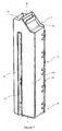
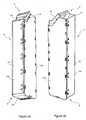
- FIG. 1 , 2a and 2b Illustrated in Figures 1 , 2a and 2b is a cartridge 10 for holding and dispensing streaking applicators (not shown in those figures, but identified in Figure 3b by reference numeral 12) for an automated streaking apparatus (not shown) having a cartridge holder 28 (described later in relation to Figures 4a, 4b , 5 and 6 ).
- the preferred type of streaking applicator 12 has a generally flat rectangular form, with two major inclined portions that together form a very shallow inverted v-shaped body. An upper portion of the body provides a mounting portion 12a and a lower portion 12b of the body provides the line of space apart contact surfaces towards the bottom of a resilient and flexible support member.
- the cartridge 10 includes a case 14 with a dispensing end A and a lower end B.
- the case 14 has a longitudinal axis Y and an elongate slot 15 therealong that is generally parallel to the longitudinal axis Y.
- the case 14 is generally cylindrical with a rectangular cross-section, thereby having four side walls (14a, 14b, 14c and 14d), a bottom wall 14e at the lower end B of the case 14, and a top wall 14f.
- This preferred orientation illustrates that the cartridge 10 is ideally elongate and is used in a generally upright orientation.
- the case 14 illustrated herein is shown as being cylindrical with a rectangular cross-section, other shapes of case are envisaged.
- the top wall 14f only partially covers the dispensing end A, there being one opening in the top wall 14f to provide a streaking device (identified in Figure 5 by reference numeral 60) with gripping access to an applicator 12 in an applicator dispensing position, and at least one other opening through which the applicator 12 may pass to be removed from the cartridge 10 by the streaking device 60.
- a streaking device identified in Figure 5 by reference numeral 60
- the top wall 14f thus includes an upper applicator-gripping opening 16 and a side applicator-dispensing opening 18, the gripping opening 16 being sized to reveal the mounting portion 12a of an applicator 12 in the dispensing position, and the dispensing opening 18 being sized to permit that applicator 12 to be slid sideways from a stack of applicators 12 from under the top wall 14f (the position occupied by the applicator marked as X in Figure 3b ) out of the cartridge 10.
- the underside of the top wall 14f is configured to conform to the shape of an applicator 12 such that the uppermost applicator X in the stack (being the applicator in the dispensing position) neatly abuts against the underside of the top wall 14f, as will be explained below, in which position the mounting portion 12a of that applicator X is accessible through the gripping opening 16 and the applicator X itself is removable via the dispensing opening 18.
- the uppermost applicator X in the stack of applicators is said to be operatively accessible from outside the case 14 of the cartridge 10.
- the cartridge 10 also includes an applicator support member 20 that is constrained within the case 14 for longitudinal movement therein in the direction of arrow Z (shown in Figure 3a ) and is able to carry the stack of applicators.
- the support member 20 is also rectangular in cross-section and is sized for sliding movement within the case 14.
- the support member 20 is shown having ratchet-type resiliently biased engaging members 22 on two of the opposed sides 24 thereof (only one being visible in Figures 3a and 3b ), capable of engaging with a series of corresponding abutments 26 along opposed interior surfaces 28 (only one being visible in Figures 3a and 3b ) of two of the side walls (14b, 14d) of the case 14, in a manner that only permits one way movement of the support member 20 towards the dispensing end A of the case 14.
- the elongate slot 15 is capable of operatively receiving a biasing member 30 when the cartridge 10 is in a cartridge holder 28 (shown in Figures 4a, 4b , 5 and 6 ) to urge the support member 20 towards the dispensing end A, forcing the uppermost applicator X against the underside of the top wall 14f and into the dispensing position.
- the biasing member 30 is a biased abutment 32 configured at least partially within the housing 34 of the cartridge holder 28, the abutment 32 being sized and located so as to fit within, and be received by, the elongate slot 15 of the cartridge 10.
- the biasing for the biased abutment 32 is provided by a spring, such as by a torsion spring 36 arranged to urge the biasing member 30 upwards along a guide-rail 38.
- Figure 4a shows the biasing member 30 in its lowermost position (which is the position it would take if a fully loaded cartridge 10 where located within the cartridge holder 28), whereas Figure 4b shows the biasing member 30 in a position part way towards the dispensing end A of a cartridge 10 that would be within the cartridge holder 28, when half of the applicators 12 therein had been dispensed.
- the elongate slot 15 is shown arranged longitudinally along one of the side walls 14b of the case 14, extending into the bottom wall 14e of the case 14 at its lower end B to allow inserting access of the abutment 32 into the slot 15 from below when the cartridge 10 is slid into the housing 28.
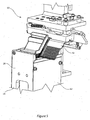
- FIG. 6 illustrates a part of such a streaking apparatus that includes multiple cartridge holders 28 (some of which, such as cartridge holders 28a, are shown without of a cartridge 10 therein) in order to be able to hold multiple cartridges 10 (as seen in cartridge holders 28b) and thus store, ready for dispensing, a very large number of streaking applicators 12, in a manner such that the streaking device 60 mentioned above is able to selectively access any one of the cartridges 10 to obtain a streaking applicator 12 therefrom, such as is shown in the schematic representation of Figure 5 .
- Each cartridge holder 28 includes a housing 34 configured and sized so as to receive a cartridge 10 within its interior, ideally to slidably receive the cartridge 10 in a close fit therein.
- the housing 34 is thus shown including therewithin, the biasing member 30 mentioned above that operatively interacts with the elongate slot 15 of the casing 14 and the applicator support member 20.
- the housing 34 also includes a cartridge lock 40 that releasably engages with the cartridge 10 when in the cartridge holder 28 to secure the cartridge 10 in place.
- the biasing member 30 includes a spring 31 to assist the release of the cartridge 10 when the cartridge lock 40 is released.
- Each housing 34 is shown configured and oriented such that, when a cartridge 10 is housed therein, the applicator dispensing position of the cartridge 10 (which is at the upper, dispensing end A of the cartridge 10) can be operatively accessed by the streaking device 60 of the streaking apparatus.
- the housing need not be a fully enclosed housing, in that it includes complete side walls or the like, although as is evident in Figure 5 , side walls 62 can be incorporated.
- a loaded cartridge 10 loaded with a stack of applicators 12 supported within the case 14 upon the support member 20
- the abutment 32 enters the slot 15 and engages with the underside of the support member 20.
- the biasing of the abutment 32 is then such as to continuously urge the support member 20 towards the dispensing end A of the case 14 so that the uppermost applicator X in the stack is always urged into, and held in, the dispensing position.
- the case 14 of the cartridge 10 in this embodiment is formed such that one of the four walls is detachably removable to provide easy access to the interior thereof such that the cartridge 10 can be re-loaded if required.
- the removable wall is the side wall 14d opposite the side wall 14b that includes the elongate slot 15.
Landscapes
- Health & Medical Sciences (AREA)
- Chemical & Material Sciences (AREA)
- Life Sciences & Earth Sciences (AREA)
- Engineering & Computer Science (AREA)
- Bioinformatics & Cheminformatics (AREA)
- Organic Chemistry (AREA)
- Wood Science & Technology (AREA)
- Zoology (AREA)
- Biochemistry (AREA)
- Biomedical Technology (AREA)
- General Health & Medical Sciences (AREA)
- Genetics & Genomics (AREA)
- Sustainable Development (AREA)
- Microbiology (AREA)
- Biotechnology (AREA)
- General Engineering & Computer Science (AREA)
- Chemical Kinetics & Catalysis (AREA)
- Clinical Laboratory Science (AREA)
- Physics & Mathematics (AREA)
- Molecular Biology (AREA)
- Medicinal Chemistry (AREA)
- Analytical Chemistry (AREA)
- General Physics & Mathematics (AREA)
- Immunology (AREA)
- Pathology (AREA)
- Automatic Analysis And Handling Materials Therefor (AREA)
- Apparatus Associated With Microorganisms And Enzymes (AREA)
- Cartons (AREA)
Applications Claiming Priority (2)
| Application Number | Priority Date | Filing Date | Title |
|---|---|---|---|
| AU2007900144A AU2007900144A0 (en) | 2007-01-12 | A streaking applicator cartridge and a system for connecting same to a streaking apparatus | |
| PCT/AU2008/000015 WO2008083438A1 (en) | 2007-01-12 | 2008-01-11 | A streaking applicator cartridge and a system for connecting same to a streaking apparatus |
Publications (3)
| Publication Number | Publication Date |
|---|---|
| EP2099895A1 EP2099895A1 (en) | 2009-09-16 |
| EP2099895A4 EP2099895A4 (en) | 2013-12-04 |
| EP2099895B1 true EP2099895B1 (en) | 2015-07-22 |
Family
ID=39608259
Family Applications (1)
| Application Number | Title | Priority Date | Filing Date |
|---|---|---|---|
| EP08700005.5A Active EP2099895B1 (en) | 2007-01-12 | 2008-01-11 | A streaking applicator cartridge and a system for connecting same to a streaking apparatus |
Country Status (7)
Families Citing this family (1)
| Publication number | Priority date | Publication date | Assignee | Title |
|---|---|---|---|---|
| US11016007B2 (en) * | 2014-04-01 | 2021-05-25 | Bd Kiestra B.V. | System and method for the automated preparation of biological samples |
Family Cites Families (73)
| Publication number | Priority date | Publication date | Assignee | Title |
|---|---|---|---|---|
| US3455788A (en) | 1966-11-15 | 1969-07-15 | Lever Brothers Ltd | Multiple inoculation device |
| US3632478A (en) | 1968-11-25 | 1972-01-04 | Aaron J Fink | Disposable culture assembly |
| US3623958A (en) | 1969-03-20 | 1971-11-30 | North American Rockwell | Automated streaking device for isolating micro-organisms on an agar surface |
| US3660243A (en) | 1970-03-16 | 1972-05-02 | North American Rockwell | Petri dish with compartment for sterilized spreading element |
| US3830701A (en) | 1970-09-08 | 1974-08-20 | Hycel Inc | Automatic petri dish streaking methods and apparatus |
| US3778351A (en) | 1971-03-16 | 1973-12-11 | Oregon Res Inst | Automatic bacterial specimen streaker |
| US3799844A (en) | 1971-06-02 | 1974-03-26 | Us Health | Instrumental method for plating and counting aerobic bacteria |
| US3788951A (en) | 1971-12-07 | 1974-01-29 | Der Pfordten H Von | Method for growing monocultures |
| US3850754A (en) | 1973-01-24 | 1974-11-26 | Nasa | Automatic inoculating apparatus |
| US3962040A (en) | 1974-03-14 | 1976-06-08 | The United States Of America As Represented By The Department Of Health, Education And Welfare | Method and apparatus for plating and counting aerobic bacteria |
| US3935075A (en) | 1974-05-13 | 1976-01-27 | Diagnostic Research, Inc. | Automatic bacterial specimen streaker and method for using same |
| US4010077A (en) | 1975-02-24 | 1977-03-01 | George Pardos | Bacteriological transfer loop |
| US4287301A (en) | 1976-04-21 | 1981-09-01 | Astle Thomas W | Method and apparatus for streaking agar |
| GB1526037A (en) | 1976-07-31 | 1978-09-27 | Mpj Dev Ltd | Apparatus for spreading inoculant on culture plates |
| US4102748A (en) | 1977-11-09 | 1978-07-25 | Mary Frances Vacanti | Device for plating and streaking a microbiological sample |
| US4170861A (en) | 1978-04-07 | 1979-10-16 | New Brunswick Scientific Co., Inc. | Method and apparatus for filling petri dishes |
| US4279861A (en) * | 1979-05-09 | 1981-07-21 | Eastman Kodak Company | Cartridge discriminator for an automated analysis system |
| GB2025457B (en) | 1978-06-13 | 1982-09-15 | Anagnostopoulos Gd | Spiral plating apparatus |
| US4613573A (en) | 1982-05-20 | 1986-09-23 | Hitachi, Ltd. | Automatic bacterial colony transfer apparatus |
| IL70737A (en) | 1984-01-20 | 1987-02-27 | Univ Ramot | Microorganism culture-transfer device |
| DE3586892T2 (de) | 1984-09-18 | 1993-05-06 | Sumitomo Electric Industries | Vorrichtung zum trennen von zellen. |
| US4659673A (en) | 1985-11-01 | 1987-04-21 | Brown Lewis R | Replicator for cultures of microorganisms |
| CA1302932C (en) * | 1986-04-18 | 1992-06-09 | Colin Wylie | Method and apparatus for streaking a culture medium |
| SE459258B (sv) | 1987-04-16 | 1989-06-19 | Bioinvent Int Ab | Anordning och foerfarande foer spridning av mikroorganismer |
| JPH01191678A (ja) | 1988-01-28 | 1989-08-01 | Hitachi Electron Eng Co Ltd | 自動プレーティング装置 |
| JPH0272898A (ja) | 1988-09-09 | 1990-03-13 | Erumetsukusu:Kk | 培地上への被検物の塗沫方法及びその装置 |
| US4892831A (en) | 1988-12-19 | 1990-01-09 | Evergreen Industries, Inc. | Inoculating device |
| JPH0349676A (ja) | 1989-07-18 | 1991-03-04 | Takeda Chem Ind Ltd | Mic及び生菌数の測定自動化装置および自動測定方法 |
| JP2815912B2 (ja) | 1989-07-28 | 1998-10-27 | 株式会社大日本精機 | シャーレ移送装置 |
| JPH03133375A (ja) | 1989-10-18 | 1991-06-06 | Takeda Chem Ind Ltd | 寒天培地表面への接種液塗布装置 |
| JPH03175996A (ja) | 1989-12-04 | 1991-07-31 | Asutemu Eng:Kk | 培地に対する検体の塗抹方法及び装置 |
| GB2247076A (en) | 1990-08-16 | 1992-02-19 | Health Lab Service Board | Multi-inoculation apparatus |
| FR2668495B1 (fr) | 1990-10-26 | 1993-10-08 | Bernard Lange | Cone de prelevement a usage bacteriologique. |
| US5206171A (en) | 1990-12-17 | 1993-04-27 | Her Majesty The Queen In Right Of Canada | Programmable automated inoculator/replicator |
| JPH04234973A (ja) | 1990-12-29 | 1992-08-24 | Dainippon Seiki:Kk | 細菌類培養装置 |
| JPH04248980A (ja) | 1991-01-31 | 1992-09-04 | Dainippon Seiki:Kk | 自動微生物試験装置 |
| US5466583A (en) | 1991-05-01 | 1995-11-14 | Thomson; Kenneth S. | Method and apparatus for performing 3-dimensional antibiotic susceptibility tests |
| DE69331861T2 (de) * | 1992-01-16 | 2002-08-29 | Fuji Photo Film Co., Ltd. | Chemisches Analysesystem |
| JPH05225995A (ja) | 1992-02-12 | 1993-09-03 | Mitsubishi Electric Corp | 燃料電池 |
| MY136048A (en) | 1992-05-22 | 2008-08-29 | Chong Sue Kheng | Culturing of micro-organisms |
| NL9200909A (nl) | 1992-05-22 | 1993-12-16 | Prolion Dev B V | Inrichting voor het op een voedingsbodem brengen van een vloeistofmonster. |
| JPH05344535A (ja) | 1992-06-05 | 1993-12-24 | Matsushita Electric Ind Co Ltd | 補強信号が付加された映像信号の磁気記録再生装置 |
| JP3382990B2 (ja) | 1993-02-01 | 2003-03-04 | 株式会社大日本精機 | 自動培地分注装置 |
| JP3414431B2 (ja) | 1993-02-19 | 2003-06-09 | 株式会社アステムエンジニアリング | 検査対象物の自動塗沫装置 |
| JPH0767695A (ja) | 1993-09-03 | 1995-03-14 | Snow Brand Milk Prod Co Ltd | 検体の塗抹方法およびその装置 |
| JPH07170970A (ja) | 1993-12-20 | 1995-07-11 | Erumetsukusu:Kk | 検体自動塗抹装置 |
| FR2717186B1 (fr) | 1994-03-10 | 1996-06-07 | Bio Merieux | Dispositif applicateur d'un élément plat de prélèvement de microorganismes, tel qu'une boîte de Pétri. |
| JP3425795B2 (ja) * | 1994-03-11 | 2003-07-14 | 富士写真フイルム株式会社 | 分析フイルム片有無判定方法 |
| DE19520420C2 (de) | 1995-06-02 | 2002-12-05 | Symbio Herborn Group Gmbh & Co | Beimpfung von Nährböden mit Keimen |
| US5756304A (en) | 1995-07-14 | 1998-05-26 | Molecular Solutions | Screening of microorganisms for bioremediation |
| JPH104952A (ja) | 1996-06-26 | 1998-01-13 | Kayagaki Irika Kogyo Kk | 培地塗布装置及び培地塗布方法 |
| GB2337589B (en) | 1997-03-17 | 2001-08-01 | Canadian Space Agency | Method and apparatus for automatically inoculating culture media with bacterial specimens from clinical specimen containers |
| JPH10309199A (ja) | 1997-05-13 | 1998-11-24 | Yoshikawa Kogyo Co Ltd | 検体の自動塗布方法と装置 |
| JP4278717B2 (ja) | 1997-05-23 | 2009-06-17 | ベクトン・ディキンソン・アンド・カンパニー | 自動化微生物学的試験装置およびその方法 |
| JPH11346796A (ja) | 1998-06-08 | 1999-12-21 | Soichi Nakagawa | 微生物検体の検査方法 |
| US6291234B1 (en) | 1998-08-25 | 2001-09-18 | Morphometrix Technologies Inc. | Method and apparatus for transferring a biological specimen to a cellular suspension |
| US6932527B2 (en) * | 1999-01-25 | 2005-08-23 | Fargo Electronics, Inc. | Card cartridge |
| DE60020722T2 (de) | 1999-08-17 | 2006-05-04 | Ttp Labtech Ltd., Royston | Probeentnahme- und -abgabegerät mit kolben und um den kolben herum gearbeitetes gehäuse |
| JP2001149063A (ja) | 1999-11-24 | 2001-06-05 | Nittetsu Mining Co Ltd | 検体検査サンプル自動作成装置 |
| JP2001153761A (ja) | 1999-11-24 | 2001-06-08 | Nittetsu Mining Co Ltd | 試料液分注方法及びその装置 |
| JP2001149062A (ja) | 1999-11-24 | 2001-06-05 | Nittetsu Mining Co Ltd | トレイ型シャーレ収容装置及びこれを備えた検体検査サンプル自動作成装置 |
| DE10011310C2 (de) | 2000-03-10 | 2002-02-28 | Micro Med Ges Fuer Angewandte | Vorrichtung zum Züchten von Keimkulturen |
| US6521190B1 (en) | 2000-05-19 | 2003-02-18 | Digene Corporation | Cell collection apparatus |
| JP2002098704A (ja) | 2000-09-25 | 2002-04-05 | Olympus Optical Co Ltd | 細菌類の自動分析装置 |
| US20020120214A1 (en) | 2000-12-29 | 2002-08-29 | Robert Cole | Spatula for biological sampling |
| US6843962B2 (en) | 2001-09-06 | 2005-01-18 | Genetix Limited | Apparatus for and methods of handling biological sample containers |
| GB0220735D0 (en) | 2002-09-06 | 2002-10-16 | Secr Defence | Innoculation method and related apparatus |
| US7597847B2 (en) * | 2003-03-31 | 2009-10-06 | Ortho-Clinical Diagnostics, Inc. | Analyzer having a stationary multifunction probe |
| JP2005052069A (ja) | 2003-08-04 | 2005-03-03 | Olympus Corp | 培養処理装置および自動培養装置 |
| KR101160240B1 (ko) | 2004-01-22 | 2012-06-26 | 메드벳 싸이언스 피티와이 엘티디 | 미생물의 획선도말 장치 |
| GB2411894B (en) | 2004-03-11 | 2007-09-26 | Mast Group Ltd | Dispensing device |
| EP1802739A2 (en) | 2004-10-13 | 2007-07-04 | Merck & Co., Inc. | Method and apparatus for automatically isolating microbial species |
| JP2008166201A (ja) | 2006-12-28 | 2008-07-17 | Mt Picture Display Co Ltd | 電界放出型電子源素子及び撮像装置 |
-
2008
- 2008-01-11 CN CN2008800018614A patent/CN101636483B/zh active Active
- 2008-01-11 AU AU2008204727A patent/AU2008204727B2/en active Active
- 2008-01-11 ES ES08700005.5T patent/ES2547861T3/es active Active
- 2008-01-11 US US12/520,974 patent/US9029129B2/en active Active
- 2008-01-11 JP JP2009545038A patent/JP5057403B2/ja active Active
- 2008-01-11 WO PCT/AU2008/000015 patent/WO2008083438A1/en active Application Filing
- 2008-01-11 EP EP08700005.5A patent/EP2099895B1/en active Active
-
2015
- 2015-05-06 US US14/705,235 patent/US9939357B2/en active Active
Also Published As
| Publication number | Publication date |
|---|---|
| ES2547861T3 (es) | 2015-10-09 |
| US20100099181A1 (en) | 2010-04-22 |
| EP2099895A1 (en) | 2009-09-16 |
| US9029129B2 (en) | 2015-05-12 |
| AU2008204727A1 (en) | 2008-07-17 |
| WO2008083438A1 (en) | 2008-07-17 |
| JP2010515438A (ja) | 2010-05-13 |
| US20150233801A1 (en) | 2015-08-20 |
| US9939357B2 (en) | 2018-04-10 |
| CN101636483B (zh) | 2013-03-27 |
| AU2008204727B2 (en) | 2013-09-19 |
| JP5057403B2 (ja) | 2012-10-24 |
| CN101636483A (zh) | 2010-01-27 |
| EP2099895A4 (en) | 2013-12-04 |
Similar Documents
| Publication | Publication Date | Title |
|---|---|---|
| EP2099896B1 (en) | Method and apparatus for inoculating and streaking a medium in a plate | |
| AU2008204729B2 (en) | Method and apparatus for orientating a solid growth culture medium plate | |
| US9751084B2 (en) | Biological culture assembly | |
| US9389153B2 (en) | Container system for tissue stabilization for molecular and histopathology diagnostics | |
| US8323957B2 (en) | Device and method for the incubation of cells | |
| US9983308B2 (en) | Method and apparatus for locating the surface of solid growth culture media in a plate | |
| JP2012526559A (ja) | 微生物の自動検出装置 | |
| EP2321402B1 (en) | Holder for culture plates with de-nesting feature | |
| US9939357B2 (en) | System for the connection of a loaded cartridge to a cartridge holder | |
| JPH0728720B2 (ja) | 細胞培養装置 | |
| WO2025045860A1 (en) | Sample rack | |
| CN221986931U (zh) | 一种生化培养箱 | |
| JPS6270760A (ja) | 化学/生物学的テスト方法及びその装置 | |
| US11306282B1 (en) | Modular multiple media tray system |
Legal Events
| Date | Code | Title | Description |
|---|---|---|---|
| PUAI | Public reference made under article 153(3) epc to a published international application that has entered the european phase |
Free format text: ORIGINAL CODE: 0009012 |
|
| 17P | Request for examination filed |
Effective date: 20090625 |
|
| AK | Designated contracting states |
Kind code of ref document: A1 Designated state(s): AT BE BG CH CY CZ DE DK EE ES FI FR GB GR HR HU IE IS IT LI LT LU LV MC MT NL NO PL PT RO SE SI SK TR |
|
| RIN1 | Information on inventor provided before grant (corrected) |
Inventor name: DUNCAN, PHILLIP, JAMES Inventor name: LECKENBY, STEPHEN, LEWIS Inventor name: ANNEAR, RYAN, ANDREW Inventor name: POTTER, COLIN, WILLIAM Inventor name: GUPTA, RAJIV |
|
| DAX | Request for extension of the european patent (deleted) | ||
| RAP1 | Party data changed (applicant data changed or rights of an application transferred) |
Owner name: LBT INNOVATIONS LIMITED |
|
| A4 | Supplementary search report drawn up and despatched |
Effective date: 20131106 |
|
| RIC1 | Information provided on ipc code assigned before grant |
Ipc: C12M 1/26 20060101AFI20131030BHEP Ipc: B65D 85/62 20060101ALI20131030BHEP Ipc: B65D 83/08 20060101ALI20131030BHEP Ipc: C12M 1/32 20060101ALI20131030BHEP |
|
| GRAP | Despatch of communication of intention to grant a patent |
Free format text: ORIGINAL CODE: EPIDOSNIGR1 |
|
| INTG | Intention to grant announced |
Effective date: 20150126 |
|
| GRAS | Grant fee paid |
Free format text: ORIGINAL CODE: EPIDOSNIGR3 |
|
| GRAA | (expected) grant |
Free format text: ORIGINAL CODE: 0009210 |
|
| AK | Designated contracting states |
Kind code of ref document: B1 Designated state(s): AT BE BG CH CY CZ DE DK EE ES FI FR GB GR HR HU IE IS IT LI LT LU LV MC MT NL NO PL PT RO SE SI SK TR |
|
| REG | Reference to a national code |
Ref country code: GB Ref legal event code: FG4D |
|
| REG | Reference to a national code |
Ref country code: CH Ref legal event code: EP |
|
| REG | Reference to a national code |
Ref country code: IE Ref legal event code: FG4D |
|
| REG | Reference to a national code |
Ref country code: AT Ref legal event code: REF Ref document number: 737933 Country of ref document: AT Kind code of ref document: T Effective date: 20150815 |
|
| REG | Reference to a national code |
Ref country code: DE Ref legal event code: R096 Ref document number: 602008039118 Country of ref document: DE |
|
| REG | Reference to a national code |
Ref country code: ES Ref legal event code: FG2A Ref document number: 2547861 Country of ref document: ES Kind code of ref document: T3 Effective date: 20151009 |
|
| REG | Reference to a national code |
Ref country code: AT Ref legal event code: MK05 Ref document number: 737933 Country of ref document: AT Kind code of ref document: T Effective date: 20150722 |
|
| REG | Reference to a national code |
Ref country code: LT Ref legal event code: MG4D |
|
| REG | Reference to a national code |
Ref country code: NL Ref legal event code: MP Effective date: 20150722 |
|
| REG | Reference to a national code |
Ref country code: FR Ref legal event code: PLFP Year of fee payment: 9 |
|
| PG25 | Lapsed in a contracting state [announced via postgrant information from national office to epo] |
Ref country code: LT Free format text: LAPSE BECAUSE OF FAILURE TO SUBMIT A TRANSLATION OF THE DESCRIPTION OR TO PAY THE FEE WITHIN THE PRESCRIBED TIME-LIMIT Effective date: 20150722 Ref country code: LV Free format text: LAPSE BECAUSE OF FAILURE TO SUBMIT A TRANSLATION OF THE DESCRIPTION OR TO PAY THE FEE WITHIN THE PRESCRIBED TIME-LIMIT Effective date: 20150722 Ref country code: NO Free format text: LAPSE BECAUSE OF FAILURE TO SUBMIT A TRANSLATION OF THE DESCRIPTION OR TO PAY THE FEE WITHIN THE PRESCRIBED TIME-LIMIT Effective date: 20151022 Ref country code: FI Free format text: LAPSE BECAUSE OF FAILURE TO SUBMIT A TRANSLATION OF THE DESCRIPTION OR TO PAY THE FEE WITHIN THE PRESCRIBED TIME-LIMIT Effective date: 20150722 Ref country code: GR Free format text: LAPSE BECAUSE OF FAILURE TO SUBMIT A TRANSLATION OF THE DESCRIPTION OR TO PAY THE FEE WITHIN THE PRESCRIBED TIME-LIMIT Effective date: 20151023 |
|
| PG25 | Lapsed in a contracting state [announced via postgrant information from national office to epo] |
Ref country code: SE Free format text: LAPSE BECAUSE OF FAILURE TO SUBMIT A TRANSLATION OF THE DESCRIPTION OR TO PAY THE FEE WITHIN THE PRESCRIBED TIME-LIMIT Effective date: 20150722 Ref country code: PL Free format text: LAPSE BECAUSE OF FAILURE TO SUBMIT A TRANSLATION OF THE DESCRIPTION OR TO PAY THE FEE WITHIN THE PRESCRIBED TIME-LIMIT Effective date: 20150722 Ref country code: PT Free format text: LAPSE BECAUSE OF FAILURE TO SUBMIT A TRANSLATION OF THE DESCRIPTION OR TO PAY THE FEE WITHIN THE PRESCRIBED TIME-LIMIT Effective date: 20151123 Ref country code: HR Free format text: LAPSE BECAUSE OF FAILURE TO SUBMIT A TRANSLATION OF THE DESCRIPTION OR TO PAY THE FEE WITHIN THE PRESCRIBED TIME-LIMIT Effective date: 20150722 Ref country code: AT Free format text: LAPSE BECAUSE OF FAILURE TO SUBMIT A TRANSLATION OF THE DESCRIPTION OR TO PAY THE FEE WITHIN THE PRESCRIBED TIME-LIMIT Effective date: 20150722 Ref country code: IS Free format text: LAPSE BECAUSE OF FAILURE TO SUBMIT A TRANSLATION OF THE DESCRIPTION OR TO PAY THE FEE WITHIN THE PRESCRIBED TIME-LIMIT Effective date: 20151122 |
|
| REG | Reference to a national code |
Ref country code: DE Ref legal event code: R097 Ref document number: 602008039118 Country of ref document: DE |
|
| PG25 | Lapsed in a contracting state [announced via postgrant information from national office to epo] |
Ref country code: DK Free format text: LAPSE BECAUSE OF FAILURE TO SUBMIT A TRANSLATION OF THE DESCRIPTION OR TO PAY THE FEE WITHIN THE PRESCRIBED TIME-LIMIT Effective date: 20150722 Ref country code: EE Free format text: LAPSE BECAUSE OF FAILURE TO SUBMIT A TRANSLATION OF THE DESCRIPTION OR TO PAY THE FEE WITHIN THE PRESCRIBED TIME-LIMIT Effective date: 20150722 Ref country code: CZ Free format text: LAPSE BECAUSE OF FAILURE TO SUBMIT A TRANSLATION OF THE DESCRIPTION OR TO PAY THE FEE WITHIN THE PRESCRIBED TIME-LIMIT Effective date: 20150722 Ref country code: SK Free format text: LAPSE BECAUSE OF FAILURE TO SUBMIT A TRANSLATION OF THE DESCRIPTION OR TO PAY THE FEE WITHIN THE PRESCRIBED TIME-LIMIT Effective date: 20150722 |
|
| PLBE | No opposition filed within time limit |
Free format text: ORIGINAL CODE: 0009261 |
|
| STAA | Information on the status of an ep patent application or granted ep patent |
Free format text: STATUS: NO OPPOSITION FILED WITHIN TIME LIMIT |
|
| PG25 | Lapsed in a contracting state [announced via postgrant information from national office to epo] |
Ref country code: BE Free format text: LAPSE BECAUSE OF NON-PAYMENT OF DUE FEES Effective date: 20160131 Ref country code: RO Free format text: LAPSE BECAUSE OF FAILURE TO SUBMIT A TRANSLATION OF THE DESCRIPTION OR TO PAY THE FEE WITHIN THE PRESCRIBED TIME-LIMIT Effective date: 20150722 |
|
| 26N | No opposition filed |
Effective date: 20160425 |
|
| PG25 | Lapsed in a contracting state [announced via postgrant information from national office to epo] |
Ref country code: SI Free format text: LAPSE BECAUSE OF FAILURE TO SUBMIT A TRANSLATION OF THE DESCRIPTION OR TO PAY THE FEE WITHIN THE PRESCRIBED TIME-LIMIT Effective date: 20150722 Ref country code: LU Free format text: LAPSE BECAUSE OF FAILURE TO SUBMIT A TRANSLATION OF THE DESCRIPTION OR TO PAY THE FEE WITHIN THE PRESCRIBED TIME-LIMIT Effective date: 20160111 |
|
| REG | Reference to a national code |
Ref country code: CH Ref legal event code: PL |
|
| PG25 | Lapsed in a contracting state [announced via postgrant information from national office to epo] |
Ref country code: MC Free format text: LAPSE BECAUSE OF FAILURE TO SUBMIT A TRANSLATION OF THE DESCRIPTION OR TO PAY THE FEE WITHIN THE PRESCRIBED TIME-LIMIT Effective date: 20150722 |
|
| PG25 | Lapsed in a contracting state [announced via postgrant information from national office to epo] |
Ref country code: CH Free format text: LAPSE BECAUSE OF NON-PAYMENT OF DUE FEES Effective date: 20160131 Ref country code: LI Free format text: LAPSE BECAUSE OF NON-PAYMENT OF DUE FEES Effective date: 20160131 |
|
| REG | Reference to a national code |
Ref country code: IE Ref legal event code: MM4A |
|
| PG25 | Lapsed in a contracting state [announced via postgrant information from national office to epo] |
Ref country code: BE Free format text: LAPSE BECAUSE OF FAILURE TO SUBMIT A TRANSLATION OF THE DESCRIPTION OR TO PAY THE FEE WITHIN THE PRESCRIBED TIME-LIMIT Effective date: 20150722 |
|
| REG | Reference to a national code |
Ref country code: FR Ref legal event code: PLFP Year of fee payment: 10 |
|
| PG25 | Lapsed in a contracting state [announced via postgrant information from national office to epo] |
Ref country code: IE Free format text: LAPSE BECAUSE OF NON-PAYMENT OF DUE FEES Effective date: 20160111 |
|
| PG25 | Lapsed in a contracting state [announced via postgrant information from national office to epo] |
Ref country code: NL Free format text: LAPSE BECAUSE OF FAILURE TO SUBMIT A TRANSLATION OF THE DESCRIPTION OR TO PAY THE FEE WITHIN THE PRESCRIBED TIME-LIMIT Effective date: 20150722 |
|
| PG25 | Lapsed in a contracting state [announced via postgrant information from national office to epo] |
Ref country code: MT Free format text: LAPSE BECAUSE OF FAILURE TO SUBMIT A TRANSLATION OF THE DESCRIPTION OR TO PAY THE FEE WITHIN THE PRESCRIBED TIME-LIMIT Effective date: 20150722 |
|
| REG | Reference to a national code |
Ref country code: FR Ref legal event code: PLFP Year of fee payment: 11 |
|
| PG25 | Lapsed in a contracting state [announced via postgrant information from national office to epo] |
Ref country code: CY Free format text: LAPSE BECAUSE OF FAILURE TO SUBMIT A TRANSLATION OF THE DESCRIPTION OR TO PAY THE FEE WITHIN THE PRESCRIBED TIME-LIMIT Effective date: 20150722 Ref country code: HU Free format text: LAPSE BECAUSE OF FAILURE TO SUBMIT A TRANSLATION OF THE DESCRIPTION OR TO PAY THE FEE WITHIN THE PRESCRIBED TIME-LIMIT; INVALID AB INITIO Effective date: 20080111 |
|
| PG25 | Lapsed in a contracting state [announced via postgrant information from national office to epo] |
Ref country code: TR Free format text: LAPSE BECAUSE OF FAILURE TO SUBMIT A TRANSLATION OF THE DESCRIPTION OR TO PAY THE FEE WITHIN THE PRESCRIBED TIME-LIMIT Effective date: 20150722 Ref country code: MT Free format text: LAPSE BECAUSE OF FAILURE TO SUBMIT A TRANSLATION OF THE DESCRIPTION OR TO PAY THE FEE WITHIN THE PRESCRIBED TIME-LIMIT Effective date: 20160131 |
|
| PG25 | Lapsed in a contracting state [announced via postgrant information from national office to epo] |
Ref country code: BG Free format text: LAPSE BECAUSE OF FAILURE TO SUBMIT A TRANSLATION OF THE DESCRIPTION OR TO PAY THE FEE WITHIN THE PRESCRIBED TIME-LIMIT Effective date: 20150722 |
|
| REG | Reference to a national code |
Ref country code: DE Ref legal event code: R082 Ref document number: 602008039118 Country of ref document: DE Representative=s name: MANITZ FINSTERWALD PATENT- UND RECHTSANWALTSPA, DE Ref country code: DE Ref legal event code: R082 Ref document number: 602008039118 Country of ref document: DE Representative=s name: MANITZ FINSTERWALD PATENTANWAELTE PARTMBB, DE Ref country code: DE Ref legal event code: R081 Ref document number: 602008039118 Country of ref document: DE Owner name: AUTOBIO DIAGNOSTICS CO., LTD., CN Free format text: FORMER OWNER: LBT INNOVATIONS LTD., ADELAIDE, SA, AU |
|
| REG | Reference to a national code |
Ref country code: GB Ref legal event code: 732E Free format text: REGISTERED BETWEEN 20180823 AND 20180829 |
|
| REG | Reference to a national code |
Ref country code: ES Ref legal event code: PC2A Owner name: AUTOBIO DIAGNOSTICS CO. LTD. Effective date: 20200817 |
|
| PGFP | Annual fee paid to national office [announced via postgrant information from national office to epo] |
Ref country code: DE Payment date: 20250327 Year of fee payment: 18 |
|
| PGFP | Annual fee paid to national office [announced via postgrant information from national office to epo] |
Ref country code: FR Payment date: 20250127 Year of fee payment: 18 |
|
| PGFP | Annual fee paid to national office [announced via postgrant information from national office to epo] |
Ref country code: IT Payment date: 20250124 Year of fee payment: 18 Ref country code: GB Payment date: 20250119 Year of fee payment: 18 |
|
| PGFP | Annual fee paid to national office [announced via postgrant information from national office to epo] |
Ref country code: ES Payment date: 20250422 Year of fee payment: 18 |