EP2099403B1 - Device for maintaining a patient in a position - Google Patents
Device for maintaining a patient in a position Download PDFInfo
- Publication number
- EP2099403B1 EP2099403B1 EP08701750.5A EP08701750A EP2099403B1 EP 2099403 B1 EP2099403 B1 EP 2099403B1 EP 08701750 A EP08701750 A EP 08701750A EP 2099403 B1 EP2099403 B1 EP 2099403B1
- Authority
- EP
- European Patent Office
- Prior art keywords
- contact members
- patient
- support means
- grip position
- protrudeable
- Prior art date
- Legal status (The legal status is an assumption and is not a legal conclusion. Google has not performed a legal analysis and makes no representation as to the accuracy of the status listed.)
- Not-in-force
Links
- 210000001562 sternum Anatomy 0.000 claims description 29
- 238000001356 surgical procedure Methods 0.000 claims description 17
- 210000001991 scapula Anatomy 0.000 claims description 12
- 210000000038 chest Anatomy 0.000 claims description 6
- 238000000034 method Methods 0.000 description 29
- 210000000115 thoracic cavity Anatomy 0.000 description 9
- 239000000463 material Substances 0.000 description 4
- 239000002184 metal Substances 0.000 description 3
- 210000004072 lung Anatomy 0.000 description 2
- 206010002091 Anaesthesia Diseases 0.000 description 1
- 238000001949 anaesthesia Methods 0.000 description 1
- 230000037005 anaesthesia Effects 0.000 description 1
- 230000000740 bleeding effect Effects 0.000 description 1
- 210000000988 bone and bone Anatomy 0.000 description 1
- 210000000481 breast Anatomy 0.000 description 1
- 239000012141 concentrate Substances 0.000 description 1
- 238000006073 displacement reaction Methods 0.000 description 1
- 239000004744 fabric Substances 0.000 description 1
- 238000012986 modification Methods 0.000 description 1
- 230000004048 modification Effects 0.000 description 1
- 210000003205 muscle Anatomy 0.000 description 1
- 229920003023 plastic Polymers 0.000 description 1
- 239000004033 plastic Substances 0.000 description 1
- 230000002035 prolonged effect Effects 0.000 description 1
- 230000000284 resting effect Effects 0.000 description 1
Images


Classifications
-
- A—HUMAN NECESSITIES
- A61—MEDICAL OR VETERINARY SCIENCE; HYGIENE
- A61G—TRANSPORT, PERSONAL CONVEYANCES, OR ACCOMMODATION SPECIALLY ADAPTED FOR PATIENTS OR DISABLED PERSONS; OPERATING TABLES OR CHAIRS; CHAIRS FOR DENTISTRY; FUNERAL DEVICES
- A61G13/00—Operating tables; Auxiliary appliances therefor
- A61G13/10—Parts, details or accessories
- A61G13/12—Rests specially adapted therefor; Arrangements of patient-supporting surfaces
- A61G13/1205—Rests specially adapted therefor; Arrangements of patient-supporting surfaces for specific parts of the body
- A61G13/122—Upper body, e.g. chest
-
- A—HUMAN NECESSITIES
- A61—MEDICAL OR VETERINARY SCIENCE; HYGIENE
- A61G—TRANSPORT, PERSONAL CONVEYANCES, OR ACCOMMODATION SPECIALLY ADAPTED FOR PATIENTS OR DISABLED PERSONS; OPERATING TABLES OR CHAIRS; CHAIRS FOR DENTISTRY; FUNERAL DEVICES
- A61G13/00—Operating tables; Auxiliary appliances therefor
- A61G13/10—Parts, details or accessories
- A61G13/12—Rests specially adapted therefor; Arrangements of patient-supporting surfaces
- A61G13/1205—Rests specially adapted therefor; Arrangements of patient-supporting surfaces for specific parts of the body
- A61G13/121—Head or neck
-
- A—HUMAN NECESSITIES
- A61—MEDICAL OR VETERINARY SCIENCE; HYGIENE
- A61G—TRANSPORT, PERSONAL CONVEYANCES, OR ACCOMMODATION SPECIALLY ADAPTED FOR PATIENTS OR DISABLED PERSONS; OPERATING TABLES OR CHAIRS; CHAIRS FOR DENTISTRY; FUNERAL DEVICES
- A61G13/00—Operating tables; Auxiliary appliances therefor
- A61G13/10—Parts, details or accessories
- A61G13/12—Rests specially adapted therefor; Arrangements of patient-supporting surfaces
- A61G13/1205—Rests specially adapted therefor; Arrangements of patient-supporting surfaces for specific parts of the body
- A61G13/125—Ankles or feet
-
- A—HUMAN NECESSITIES
- A61—MEDICAL OR VETERINARY SCIENCE; HYGIENE
- A61G—TRANSPORT, PERSONAL CONVEYANCES, OR ACCOMMODATION SPECIALLY ADAPTED FOR PATIENTS OR DISABLED PERSONS; OPERATING TABLES OR CHAIRS; CHAIRS FOR DENTISTRY; FUNERAL DEVICES
- A61G13/00—Operating tables; Auxiliary appliances therefor
- A61G13/10—Parts, details or accessories
- A61G13/12—Rests specially adapted therefor; Arrangements of patient-supporting surfaces
- A61G13/1205—Rests specially adapted therefor; Arrangements of patient-supporting surfaces for specific parts of the body
- A61G13/1255—Shoulders
-
- A—HUMAN NECESSITIES
- A61—MEDICAL OR VETERINARY SCIENCE; HYGIENE
- A61G—TRANSPORT, PERSONAL CONVEYANCES, OR ACCOMMODATION SPECIALLY ADAPTED FOR PATIENTS OR DISABLED PERSONS; OPERATING TABLES OR CHAIRS; CHAIRS FOR DENTISTRY; FUNERAL DEVICES
- A61G13/00—Operating tables; Auxiliary appliances therefor
- A61G13/10—Parts, details or accessories
- A61G13/12—Rests specially adapted therefor; Arrangements of patient-supporting surfaces
- A61G13/128—Rests specially adapted therefor; Arrangements of patient-supporting surfaces with mechanical surface adaptations
- A61G13/1295—Rests specially adapted therefor; Arrangements of patient-supporting surfaces with mechanical surface adaptations having alignment devices for the patient's body
Definitions
- the present invention relates to a device for use after open chest surgery via sternotomy incision.
- the present invention relates to a device for maintaining a patient in a position during surgery, for instance a position in which the sternum can be closed after open chest surgery.
- Sternotomy is a surgical procedure in which an incision is made in the sternum to divide or open the sternum longitudinally to provide access to the chest cavity to allow heart and/or lung surgery.
- the forcing together of the divided sternum edges is typically achieved by an assistant surgeon or anaesthetist placing their palms underneath the patient's torso and manually raising the patient's scapulae (shoulder blades). At the same time, the surgeon pulls on the metal wires to assist in the alignment.
- the wires threaded through the patient's sternum are often used to pull the edges of the sternum together. This can result in the wires cutting through if the bone is soft or breakage of the wire. This very time consuming with potential risk of increased bleeding because all of the wires have to be removed and the wiring procedure recommenced from the start.
- DE 19848218 A1 discloses a fabric-type support which can be stretched over a bed base, on which it is suspendable and raisable by way of rotatable shafts disposed along the sides of the bed and shaft-lifting levers. Mats can be attached to the support. A patient can be moved into the required position by coordinated rotation of the shafts and movement of the shaft-lifting levers.
- US 5121512 discloses a mattress comprising a number of inflatable cells fixed to the mattress bottom and extending along the mattress. The cells are individually fillable and evacuable for changing the position of a patient lying on the mattress.
- the present invention aims to ameliorate at least some of the problems described above and provides a device which will maintain the patient in a position in which alignment of the sternum edges is facilitated without requiring excessive force. This will reduce the incidence of wire breakages/displacement and will also relieve the assistant surgeon or anaesthetist from prolonged physical effort.
- the device comprises additional means for manipulating the torso more generally e.g. to lift the spine of the patient, or to roll or wedge the patient towards one side to simplify access for the surgeon in performing the relevant procedure.
- the present invention provides a device for maintaining a patient in a position in which the patient's sternum can be closed after open chest surgery, said device comprising two contact members (1) for contacting a respective scapula and support means for maintaining the contact members (1) in a grip position in which, in use, each contact member (1) imparts a force on the respective scapula to close the patient's sternum; characterised in that: the support means is pneumatic or hydraulic and includes a respective inflatable bladder (24) located on the underside of each contact member (1); the contact members (1) include at least one protrudeable element (26) for increasing the lateral forces to the respective scapula when the contact members (1) are in the grip position; and the protrudeable element(s) (26) is/are inflatable element(s).
- the contact members take the place of the assistant surgeon's/anaesthetist's hands under the patient's scapulae. In the grip position, the contact members can apply forces, e.g. opposing lateral forces, to raise and squeeze the scapulae which closes the sternum.
- the support means can maintain the contact members in the grip position for the required period of time to allow closure of the chest cavity without requiring any physical effort by the assistant surgeon/anaesthetist and without requiring excessive tension on the wires to approximate the two edges of the sternum.
- the support means are adapted such that they can releasably maintain the contact members in the grip position. Accordingly, after closure of the chest cavity is complete, the contact members can be released from the grip position.
- the support means are adapted to move the contact members from a rest position into the grip position.
- the sternum can be closed with reduced or minimal effort on the part of the assistant surgeon/anaesthetist and without requiring excessive pulling of the metal wires.
- the support means are adapted to move the contact members from a substantially horizontal rest position in which substantially no lateral force can be applied to the scapulae into the grip position in which opposing lateral forces can be applied to the scapulae.
- each contact member can be moved by the support means into the grip position. In the grip position, each contact member can abut the respective scapula so that the contact members can raise the scapulae from the operating table and squeeze them towards each other to bring the edges of the divided sternum together.
- the support means are adapted such that they can move the contact members from the grip position back to the substantially horizontal rest position. This allows the contact members to lie flat on the operating table after closure of the chest cavity is complete so that the device does not impinge on the patient or so that it can easily be removed from under the patient.
- the support means are adapted to move the contact members into the grip position by raising at least part of the edges of the contact members which, in use, are remote from the patient's midline (hereinafter called “the outermost edges").
- the support means are pneumatic or hydraulic.
- the support means are pneumatic or hydraulic, most preferably electrically operated pneumatic or hydraulic support means so that the contact members can be moved into and maintained in the grip position without any physical effort by the assistant surgeon/aneasthetist.
- the support means includes an inflatable bladder located on the underside of each contact member (i.e. on the opposite side to that which can abut the patient in the grip position).
- the inflatable bladders are reversibly inflatable/deflatable.
- the inflatable bladders preferably have a sufficiently low profile in the deflated state that the contact members can lie substantially flat on an operating table with the inflatable bladders between the contact members and the operating table. In the inflated state, the inflatable bladders can push at least part of the contact members (e.g. the outermost edges) from the operating table into the grip position and can maintain them in this position in which the contact members can apply opposing lateral forces on the scapulae.
- the contact members may be joined to a base portion which, in use, is positioned directly under the patient's midline. This helps positioning of the device and also reduces the number of separate parts of the device.
- the contact members may be pivotable along the join with the base portion.
- the support means may be adapted to maintain a grip position in which the contact members are inclined relative to the base portion.
- the support means are adapted to pivot the contact members from the rest position in which both the contact members and the base portion are substantially horizontal, to the grip position in which the contact members are inclined relative to the base portion.
- the contact members and base portion may be integral.
- the contact members and base portion may be formed of a single sheet of flexible material e.g. cloth or plastics material.
- the outermost edges of the contact members are preferably mounted on a frame which cooperates with the support means.
- the support means can maintain a raised position of at least part of the frame e.g. above the level of an operating table, such that at least part of the outermost edges of the contact members are suspended from the frame in the grip position.
- the contact members and base portion are a single sheet of flexible material, the sheet of material can form a hammock structure in which the upper torso of a patient may be gripped.
- the frame has side arms which extend at least partly along the outermost edges of the contact members and a crossbar which joins the side arms, the crossbar cooperating with the support means.
- the crossbar can be raised to move the frame from a rest position (in which the crossbar and side arms are substantially horizontal) to the grip position in which the side arms are inclined to the horizontal so that the outermost edges of the contact members proximal the crossbar are suspended from the side arms.
- the support means can maintain the raised position of the crossbar to maintain the contact members in the grip position.
- the contact members and optionally the base portion may be formed of a series of slats e.g. padded slats, preferably extending in a direction which, in use, is parallel to the patient's midline.
- the slats have a wider base (remote from the patient in use) and a narrower top (adjacent the patient in use) when viewed in a transverse cross-section, i.e. the slats have a trapezoid shaped transverse cross section. This means that the bases of adjacent slats are closer to each other than the tops of adjacent slats.
- the bases of at least some of the slats are connected to the bases of the adjacent slat(s) at a hinge and the support means act to maintain the slats in a position in which they are pivoted at these hinges such that the tops of the adjacent slats approach each other.
- the support means are adapted to move the slats into this "curled" grip position in which the outermost slats (i.e. the contact members) can exert a lateral force on the patient's scapulae.
- the contact members include at least one protrudeable element. This at least one protrudeable element can be used for increasing the lateral forces to the respective scapula when the contact members are in the grip position.
- the contact members include a plurality of protrudeable elements. These protrudeable elements may be arranged such that, in use, they are aligned with the patient's midline or they may be arranged such that, in use, they are transverse to the patient's midline.
- the protrudeable elements are preferably selectively protrudeable.
- the elements when the elements are arranged such that, in use, they are aligned with the patient's midline, they can be selectively protruded to apply extra force on the patient's scapulae.
- extra force can be applied using protrudeable elements located, in use, proximal to the patient's midline.
- extra force can be applied using protrudeable elements located, in use, remote from the patient's midline.
- the protrudeable elements are inflatable elements.
- the device further comprises a further independent torso-moving means which is in use situated beneath the patient's midline.
- This torso-moving means may take the form of a patient's midline support means in similar terms to the support means described above (pneumatic or hydraulic).
- it is an inflatable cell which contacts the patient's spine.
- the torso moving means is adapted to rise from the base portion, thus providing for additional manipulation of the patient and offering the surgeon simplified access during surgery.
- the torso-moving means may apply pressure to open the sternum, or to angle the patient (using both the midline support and the contact members) where that might be desired e.g. during surgery on the breast.
- this torso-moving means is symmetrical and curved in cross section when raised, with the apex being adapted to contact the patient's midline. In other embodiments it may be trapezoid as described above.
- the device may be used in a method of manipulating a patient during, prior, or after, surgery.
- the method may be for maintaining a patient in a position in which the patient's sternum can be closed after open chest surgery, said method comprising: providing a device according to claim 1; positioning the contact members of the device underneath a respective scapula of the patient; moving the contact members into the grip position; and maintaining the contact members in the grip position using the support means.
- the method comprises positioning the contact members underneath a respective scapula of the patient in a substantially horizontal orientation in which substantially no lateral force is applied to the scapulae and moving the contact members into the grip position in which opposing lateral forces are applied to the scapulae.
- the method preferably comprises raising at least part of the outermost edges of the contact members.
- the method comprises moving the contact members into the grip position using the support means.
- the method comprises maintaining the contact members in the grip position by pneumatic or hydraulic support means.
- the method comprises moving the contact members to and/or maintaining the contact members in the grip position using pneumatic or hydraulic support means.
- the method comprises providing a device having an inflatable bladder located on the underside of each contact member (i.e. on the opposite side to that which can abut the patient in the grip position) and inflating the bladders to push at least part of the contact members (e.g. the outermost edges) from the operating table into the grip position.
- the method includes using inflatable bladders to maintain the outermost edges in this position in which the contact members can apply opposing lateral forces on the scapulae.
- the method comprises providing a device in which the contact members are joined to a base portion and positioning the base portion under the patient's midline.
- the method comprises pivoting the contact members at the join with the base portion from a substantially horizontal rest position to the grip position in which both contact members are inclined relative to the base.
- the method may comprise providing a device having a frame with side arms which extend at least partly along the outermost edges of the contact members and moving the frame to move the contact members into the grip position. More preferably, the method comprises providing a frame which further includes a crossbar joining the side arms and raising the crossbar, e.g. above the level of the operating table, such that the side arms are moved from a horizontal position to the grip position in which the side arms are inclined to the horizontal and the outermost edges of the contact members proximal the crossbar are suspended from the side arms.
- the method may comprise providing a device in which the contact members and optionally the base portion are formed of a series of slats e.g. padded slats, preferably extending in a direction parallel to the patient's midline.
- the slats have a wider base (remote from the patient in use) and a narrower top (adjacent the patient in use), i.e. the bases of adjacent slats are closer to each other than the tops of adjacent slats.
- the bases of at least some of the slats are connected to the bases of the adjacent slats at a pivotable hinge.
- the method preferably comprises moving the contact members by pivoting the slats at these hinges such that the tops of the slats move towards each other. This results in the contact members and base portion "curling" into the grip position which the outermost slats (i.e. the contact members) exert a lateral force on the patient's scapulae.
- the method comprises providing at least one protrudeable element on each contact member and causing the protrudeable elements to protrude from the contact member to increase the lateral force to the respective scapula in the grip position.
- the method comprises providing a plurality of protrudeable elements, preferably arranged such that they are aligned with or transverse to the patient's midline.
- the method preferably comprises selectively causing the protrudeable elements to protrude.
- the elements are aligned with the patient's midline, they are selectively protruded to apply extra force on the patient's scapulae.
- extra force is applied by causing protrudeable elements located proximal to the patient's midline to protrude.
- extra force can be applied by causing protrudeable elements located remote from the patient's midline to protrude.
- the protrudeable elements are inflatable elements and the method comprises inflating (preferably selectively inflating) the protrudeable elements.
- the method further comprises releasing the contact members from the grip position after closure of the chest cavity is complete.
- the method may comprise operating or raising the torso-moving means (if present) situated beneath the patient's midline such as to manipulate the patient to offer the surgeon simplified access during surgery - e.g. to angle the patient where that might be desired.
- the device of the present invention can be used in a method of closing a patient's sternum after open chest surgery, said method comprising: providing a device according to claim 1; positioning the contact members of the device underneath a respective scapula of the patient; moving the contact members into the grip position; maintaining the contact members in the grip position using the support means and fixing the sternum in a closed position.
- the method comprises fixing the sternum in the closed position by twisting wires attached to the patient's intersect muscles.
- Figure 1 shows a perspective view of a first preferred embodiment in the rest position.
- two contact members 1 are provided fixed to either side of a base portion 2.
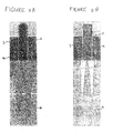
- the base portion slat is positioned directly underneath the patient's midline 14 and the contact member slats 1 are positioned underneath the patient's scapulae as shown in Figure 2A (larger patients) and 2B (smaller patients).
- each contact member is an inflatable bladder 24 (e.g. a PVC inflatable bladder) which can be seen in a deflated state (in the rest position) in Figures 3A and 4A .
- the profile of the deflated bladders is sufficiently low that the contact members can lie is a substantially horizontal plane on the operating table 4.
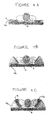
- the inflatable bladders are inflated using a compressor 25. This raises the outermost edges of the compact members 1 from the operating table so that the contact members are inclined relative to the base portion 2. In this position, the contact members 1 can exert opposing lateral forces on the scapulae to close the sternum.
- the inflatable bladders maintain the contact members 1 in the grip position until the air pressure in the bladders 24 is reduced (after fixing of the sternum).
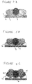
- the contact members 1 additionally include secondary inflatable bladders 26 which are protrudeable elements. When the contact members 1 are in the grip position, the opposing lateral force applied by the contact members 1 to the scapulae can be further increased by inflating the secondary inflatable bladders 26 as shown in Figures 3C and 4C .
- the secondary inflatable 26 bladders can be aligned transverse to the patient's midline as shown in Figure 5 or they can be aligned parallel to the patients' midline as shown in Figures 6A , B and C.
- Figures 6A , B and C show a second preferred embodiment which is substantially identical to the first embodiment but which has the secondary inflatable bladders 26 aligned with the patient's midline, three bladders extending the length of each contact member 1.
- Figure 6A shows the second preferred embodiment in the grip position with the secondary inflatable bladders 26 un-inflated.
- Figures 6B and 6C show how the secondary inflatable bladders 26 can be selectively inflated depending on the size of the patient i.e. the secondary inflatable bladders proximal the patient's scapulae can be selectively inflated.
- the outermost secondary inflatable bladders can be inflated as shown in Figure 6B to impart an increased force on the patient's scapulae.
- the innermost secondary inflatable bladder can be inflated as shown in Figure 6C .
- Figure 7 shows a perspective view of an embodiment of the invention in which an inflation cell, aligned with the patient's midline and arranged to contact it in use, is provided.
Landscapes
- Health & Medical Sciences (AREA)
- Engineering & Computer Science (AREA)
- Biomedical Technology (AREA)
- Life Sciences & Earth Sciences (AREA)
- Animal Behavior & Ethology (AREA)
- General Health & Medical Sciences (AREA)
- Public Health (AREA)
- Veterinary Medicine (AREA)
- Accommodation For Nursing Or Treatment Tables (AREA)
Applications Claiming Priority (2)
| Application Number | Priority Date | Filing Date | Title |
|---|---|---|---|
| GBGB0700372.6A GB0700372D0 (en) | 2007-01-09 | 2007-01-09 | Device and methods of using device |
| PCT/GB2008/000034 WO2008084203A1 (en) | 2007-01-09 | 2008-01-08 | Device for maintaining a patient in a position and methods of using it |
Publications (2)
| Publication Number | Publication Date |
|---|---|
| EP2099403A1 EP2099403A1 (en) | 2009-09-16 |
| EP2099403B1 true EP2099403B1 (en) | 2015-03-04 |
Family
ID=37801913
Family Applications (1)
| Application Number | Title | Priority Date | Filing Date |
|---|---|---|---|
| EP08701750.5A Not-in-force EP2099403B1 (en) | 2007-01-09 | 2008-01-08 | Device for maintaining a patient in a position |
Country Status (9)
Families Citing this family (15)
| Publication number | Priority date | Publication date | Assignee | Title |
|---|---|---|---|---|
| WO2015138317A1 (en) | 2014-03-10 | 2015-09-17 | Stryker Corporation | Limb positioning system |
| US9951904B2 (en) | 2015-03-24 | 2018-04-24 | Stryker Corporation | Rotatable seat clamps for rail clamp |
| US10966892B2 (en) | 2015-08-17 | 2021-04-06 | Warsaw Orthopedic, Inc. | Surgical frame facilitating articulatable support for a patient during surgery |
| US10548796B2 (en) | 2015-08-17 | 2020-02-04 | Warsaw Orthopedic, Inc. | Surgical frame and method for use thereof facilitating articulatable support for a patient during surgery |
| US10900448B2 (en) | 2017-03-10 | 2021-01-26 | Warsaw Orthopedic, Inc. | Reconfigurable surgical frame and method for use thereof |
| US10874570B2 (en) | 2017-06-30 | 2020-12-29 | Warsaw Orthopedic, Inc. | Surgical frame and method for use thereof facilitating patient transfer |
| US11020304B2 (en) * | 2017-08-08 | 2021-06-01 | Warsaw Orthopedic, Inc. | Surgical frame including main beam for facilitating patient access |
| US11116679B2 (en) * | 2017-12-13 | 2021-09-14 | Vandette B. Carter | Bed bound patient turning device |
| JP7060234B2 (ja) * | 2018-04-26 | 2022-04-26 | 長田電機工業株式会社 | 歯科用治療椅子 |
| DE102018133235A1 (de) * | 2018-12-20 | 2020-06-25 | Felix Pany | Lagerungshilfe für medizinische Untersuchungen |
| US10881570B2 (en) | 2019-04-26 | 2021-01-05 | Warsaw Orthopedic, Inc | Reconfigurable pelvic support for a surgical frame and method for use thereof |
| US11672718B2 (en) | 2019-09-25 | 2023-06-13 | Warsaw Orthopedic, Inc. | Reconfigurable upper leg support for a surgical frame |
| US11813217B2 (en) | 2020-04-22 | 2023-11-14 | Warsaw Orthopedic, Inc | Lift and method for use of a lift for positioning a patient relative to a surgical frame |
| US11304867B2 (en) | 2020-04-22 | 2022-04-19 | Warsaw Orthopedic, Inc. | Lift and method for use of a lift for positioning a patient relative to a surgical frame |
| US11147723B1 (en) | 2021-04-05 | 2021-10-19 | Nathan A. Kludt | Patient positioning device |
Family Cites Families (20)
| Publication number | Priority date | Publication date | Assignee | Title |
|---|---|---|---|---|
| US2535559A (en) * | 1949-03-15 | 1950-12-26 | Wolf Monroe | Surgical clamp |
| SE465702B (sv) | 1989-01-03 | 1991-10-21 | Irene Kaufmann | Liggunderlag med individuellt valvis fyllbara evakuerbara flexibla cellkroppar |
| US5390383A (en) * | 1993-11-15 | 1995-02-21 | Sunmed, Inc. | Anterior pelvic support device for a surgery patient |
| US5500964A (en) * | 1994-03-09 | 1996-03-26 | National Health Equipment, Inc. | Patient manipulating kit and method of converting a hospital bed to a patient manipulation apparatus |
| US6076208A (en) * | 1997-07-14 | 2000-06-20 | Hill-Rom, Inc. | Surgical stretcher |
| JPH1199159A (ja) * | 1997-09-26 | 1999-04-13 | Senko Medical Instr Mfg Co Ltd | 姿勢維持装置 |
| US5906205A (en) * | 1998-07-28 | 1999-05-25 | Hiebert; Eugene Lloyd | Surgical positioning device |
| DE19848218C2 (de) | 1998-10-20 | 2000-08-17 | Eos Werke Guenther Gmbh | Liegevorrichtung |
| GB9929407D0 (en) * | 1999-12-14 | 2000-02-09 | Rabaiotti Mario M | Patient support |
| US6298511B1 (en) * | 2000-05-04 | 2001-10-09 | Deborah D. Collymore | Articulated air mattress |
| US6358270B1 (en) * | 2000-07-27 | 2002-03-19 | Haifa Surgical Instruments Ltd. | Sternum closure device |
| US20020128576A1 (en) * | 2001-03-09 | 2002-09-12 | Mayes Billy Jack | Back rehab exercise bench |
| JP2003310668A (ja) * | 2002-02-22 | 2003-11-05 | Sanyo Electric Co Ltd | 可動ベッド |
| US6934987B2 (en) * | 2002-03-11 | 2005-08-30 | Hill-Rom Services, Inc. | Surgical table having integral lateral supports |
| US8286283B2 (en) * | 2004-05-12 | 2012-10-16 | Surgipod Pty. Ltd. | Lateral support for an operating table |
| US7681269B2 (en) * | 2005-06-01 | 2010-03-23 | Anodyne Medical Device, Inc. | Support surface with integral patient turning mechanism |
| EP1982680B1 (de) * | 2007-04-18 | 2011-07-20 | BrainLAB AG | Patienten-Seitenlagerungsvorrichtung für Beckenbehandlungen mit Vakuummatratze |
| US7857779B2 (en) * | 2008-03-06 | 2010-12-28 | Gondringer Chad J | Traction device for use in surgery |
| US8690807B2 (en) * | 2009-09-02 | 2014-04-08 | Allen Medical Systems, Inc. | Surgical positioning system |
| US8782832B2 (en) * | 2009-11-06 | 2014-07-22 | New York Society For The Ruptured And Crippled Maintaining The Hospital For Special Surgery | System, method, and apparatus for patient positioning table |
-
2007
- 2007-01-09 GB GBGB0700372.6A patent/GB0700372D0/en not_active Ceased
-
2008
- 2008-01-08 ES ES08701750.5T patent/ES2537964T3/es active Active
- 2008-01-08 EP EP08701750.5A patent/EP2099403B1/en not_active Not-in-force
- 2008-01-08 AU AU2008204392A patent/AU2008204392B2/en not_active Ceased
- 2008-01-08 CA CA2674284A patent/CA2674284C/en not_active Expired - Fee Related
- 2008-01-08 ZA ZA200904915A patent/ZA200904915B/xx unknown
- 2008-01-08 JP JP2009544445A patent/JP5237301B2/ja not_active Expired - Fee Related
- 2008-01-08 US US12/448,643 patent/US8806681B2/en not_active Expired - Fee Related
- 2008-01-08 WO PCT/GB2008/000034 patent/WO2008084203A1/en active Application Filing
-
2014
- 2014-06-05 US US14/296,942 patent/US9486379B2/en not_active Expired - Fee Related
Also Published As
| Publication number | Publication date |
|---|---|
| CA2674284C (en) | 2014-09-16 |
| ZA200904915B (en) | 2010-10-27 |
| EP2099403A1 (en) | 2009-09-16 |
| US9486379B2 (en) | 2016-11-08 |
| CA2674284A1 (en) | 2008-07-17 |
| US20140283846A1 (en) | 2014-09-25 |
| US8806681B2 (en) | 2014-08-19 |
| GB0700372D0 (en) | 2007-02-14 |
| ES2537964T3 (es) | 2015-06-16 |
| WO2008084203A1 (en) | 2008-07-17 |
| AU2008204392B2 (en) | 2013-01-31 |
| AU2008204392A1 (en) | 2008-07-17 |
| US20100088822A1 (en) | 2010-04-15 |
| JP5237301B2 (ja) | 2013-07-17 |
| JP2010515475A (ja) | 2010-05-13 |
Similar Documents
| Publication | Publication Date | Title |
|---|---|---|
| EP2099403B1 (en) | Device for maintaining a patient in a position | |
| US20210353487A1 (en) | Surgical patient support for lateral-to-prone patient positioning | |
| US20050165429A1 (en) | Surgical clamp possessing a combined parallel and scissor style clamp head | |
| US6510574B2 (en) | Inflatable positioning aids for operating room | |
| KR100354988B1 (ko) | 정체용 거꾸로 매달기 베드 장치 | |
| EP2419070B1 (en) | Backboard for an automated cpr system | |
| US4505268A (en) | Scoliosis frame | |
| CN109310510A (zh) | 医疗装置 | |
| CN112826609B (zh) | 一种可多向调节的头部气囊固定装置 | |
| CN108742978A (zh) | 一种脊柱康复训练床 | |
| CN108969278A (zh) | 普外科用腰部支撑垫 | |
| TWI760271B (zh) | 氣墊床及其控制方法 | |
| CN112057221B (zh) | 一种可拆分式颈椎理疗牵引结构及其使用方法 | |
| CN115089418B (zh) | 一种智能化可调式体位垫 | |
| KR100353266B1 (ko) | 척추 보조기 | |
| US20250228723A1 (en) | Support surface overlay with pivoting inflatable element | |
| CN113288378A (zh) | 一种安全防护性助产钳 | |
| KR20000010827U (ko) | 척추교정용 이동식 테이블 |
Legal Events
| Date | Code | Title | Description |
|---|---|---|---|
| PUAI | Public reference made under article 153(3) epc to a published international application that has entered the european phase |
Free format text: ORIGINAL CODE: 0009012 |
|
| 17P | Request for examination filed |
Effective date: 20090713 |
|
| AK | Designated contracting states |
Kind code of ref document: A1 Designated state(s): AT BE BG CH CY CZ DE DK EE ES FI FR GB GR HR HU IE IS IT LI LT LU LV MC MT NL NO PL PT RO SE SI SK TR |
|
| DAX | Request for extension of the european patent (deleted) | ||
| 17Q | First examination report despatched |
Effective date: 20111109 |
|
| GRAP | Despatch of communication of intention to grant a patent |
Free format text: ORIGINAL CODE: EPIDOSNIGR1 |
|
| INTG | Intention to grant announced |
Effective date: 20140820 |
|
| GRAS | Grant fee paid |
Free format text: ORIGINAL CODE: EPIDOSNIGR3 |
|
| GRAA | (expected) grant |
Free format text: ORIGINAL CODE: 0009210 |
|
| AK | Designated contracting states |
Kind code of ref document: B1 Designated state(s): AT BE BG CH CY CZ DE DK EE ES FI FR GB GR HR HU IE IS IT LI LT LU LV MC MT NL NO PL PT RO SE SI SK TR |
|
| REG | Reference to a national code |
Ref country code: GB Ref legal event code: FG4D |
|
| REG | Reference to a national code |
Ref country code: CH Ref legal event code: EP |
|
| REG | Reference to a national code |
Ref country code: IE Ref legal event code: FG4D |
|
| REG | Reference to a national code |
Ref country code: AT Ref legal event code: REF Ref document number: 713197 Country of ref document: AT Kind code of ref document: T Effective date: 20150415 |
|
| REG | Reference to a national code |
Ref country code: DE Ref legal event code: R096 Ref document number: 602008036933 Country of ref document: DE Effective date: 20150416 |
|
| REG | Reference to a national code |
Ref country code: ES Ref legal event code: FG2A Ref document number: 2537964 Country of ref document: ES Kind code of ref document: T3 Effective date: 20150616 |
|
| REG | Reference to a national code |
Ref country code: AT Ref legal event code: MK05 Ref document number: 713197 Country of ref document: AT Kind code of ref document: T Effective date: 20150304 Ref country code: NL Ref legal event code: VDEP Effective date: 20150304 |
|
| PG25 | Lapsed in a contracting state [announced via postgrant information from national office to epo] |
Ref country code: SE Free format text: LAPSE BECAUSE OF FAILURE TO SUBMIT A TRANSLATION OF THE DESCRIPTION OR TO PAY THE FEE WITHIN THE PRESCRIBED TIME-LIMIT Effective date: 20150304 Ref country code: FI Free format text: LAPSE BECAUSE OF FAILURE TO SUBMIT A TRANSLATION OF THE DESCRIPTION OR TO PAY THE FEE WITHIN THE PRESCRIBED TIME-LIMIT Effective date: 20150304 Ref country code: NO Free format text: LAPSE BECAUSE OF FAILURE TO SUBMIT A TRANSLATION OF THE DESCRIPTION OR TO PAY THE FEE WITHIN THE PRESCRIBED TIME-LIMIT Effective date: 20150604 Ref country code: HR Free format text: LAPSE BECAUSE OF FAILURE TO SUBMIT A TRANSLATION OF THE DESCRIPTION OR TO PAY THE FEE WITHIN THE PRESCRIBED TIME-LIMIT Effective date: 20150304 Ref country code: LT Free format text: LAPSE BECAUSE OF FAILURE TO SUBMIT A TRANSLATION OF THE DESCRIPTION OR TO PAY THE FEE WITHIN THE PRESCRIBED TIME-LIMIT Effective date: 20150304 |
|
| REG | Reference to a national code |
Ref country code: LT Ref legal event code: MG4D |
|
| PG25 | Lapsed in a contracting state [announced via postgrant information from national office to epo] |
Ref country code: LV Free format text: LAPSE BECAUSE OF FAILURE TO SUBMIT A TRANSLATION OF THE DESCRIPTION OR TO PAY THE FEE WITHIN THE PRESCRIBED TIME-LIMIT Effective date: 20150304 Ref country code: GR Free format text: LAPSE BECAUSE OF FAILURE TO SUBMIT A TRANSLATION OF THE DESCRIPTION OR TO PAY THE FEE WITHIN THE PRESCRIBED TIME-LIMIT Effective date: 20150605 Ref country code: AT Free format text: LAPSE BECAUSE OF FAILURE TO SUBMIT A TRANSLATION OF THE DESCRIPTION OR TO PAY THE FEE WITHIN THE PRESCRIBED TIME-LIMIT Effective date: 20150304 |
|
| PG25 | Lapsed in a contracting state [announced via postgrant information from national office to epo] |
Ref country code: NL Free format text: LAPSE BECAUSE OF FAILURE TO SUBMIT A TRANSLATION OF THE DESCRIPTION OR TO PAY THE FEE WITHIN THE PRESCRIBED TIME-LIMIT Effective date: 20150304 |
|
| PG25 | Lapsed in a contracting state [announced via postgrant information from national office to epo] |
Ref country code: RO Free format text: LAPSE BECAUSE OF FAILURE TO SUBMIT A TRANSLATION OF THE DESCRIPTION OR TO PAY THE FEE WITHIN THE PRESCRIBED TIME-LIMIT Effective date: 20150304 Ref country code: CZ Free format text: LAPSE BECAUSE OF FAILURE TO SUBMIT A TRANSLATION OF THE DESCRIPTION OR TO PAY THE FEE WITHIN THE PRESCRIBED TIME-LIMIT Effective date: 20150304 Ref country code: SK Free format text: LAPSE BECAUSE OF FAILURE TO SUBMIT A TRANSLATION OF THE DESCRIPTION OR TO PAY THE FEE WITHIN THE PRESCRIBED TIME-LIMIT Effective date: 20150304 Ref country code: PT Free format text: LAPSE BECAUSE OF FAILURE TO SUBMIT A TRANSLATION OF THE DESCRIPTION OR TO PAY THE FEE WITHIN THE PRESCRIBED TIME-LIMIT Effective date: 20150706 Ref country code: EE Free format text: LAPSE BECAUSE OF FAILURE TO SUBMIT A TRANSLATION OF THE DESCRIPTION OR TO PAY THE FEE WITHIN THE PRESCRIBED TIME-LIMIT Effective date: 20150304 |
|
| PG25 | Lapsed in a contracting state [announced via postgrant information from national office to epo] |
Ref country code: PL Free format text: LAPSE BECAUSE OF FAILURE TO SUBMIT A TRANSLATION OF THE DESCRIPTION OR TO PAY THE FEE WITHIN THE PRESCRIBED TIME-LIMIT Effective date: 20150304 Ref country code: IS Free format text: LAPSE BECAUSE OF FAILURE TO SUBMIT A TRANSLATION OF THE DESCRIPTION OR TO PAY THE FEE WITHIN THE PRESCRIBED TIME-LIMIT Effective date: 20150704 |
|
| REG | Reference to a national code |
Ref country code: DE Ref legal event code: R097 Ref document number: 602008036933 Country of ref document: DE |
|
| PLBE | No opposition filed within time limit |
Free format text: ORIGINAL CODE: 0009261 |
|
| STAA | Information on the status of an ep patent application or granted ep patent |
Free format text: STATUS: NO OPPOSITION FILED WITHIN TIME LIMIT |
|
| REG | Reference to a national code |
Ref country code: FR Ref legal event code: PLFP Year of fee payment: 9 |
|
| PG25 | Lapsed in a contracting state [announced via postgrant information from national office to epo] |
Ref country code: DK Free format text: LAPSE BECAUSE OF FAILURE TO SUBMIT A TRANSLATION OF THE DESCRIPTION OR TO PAY THE FEE WITHIN THE PRESCRIBED TIME-LIMIT Effective date: 20150304 |
|
| 26N | No opposition filed |
Effective date: 20151207 |
|
| PG25 | Lapsed in a contracting state [announced via postgrant information from national office to epo] |
Ref country code: SI Free format text: LAPSE BECAUSE OF FAILURE TO SUBMIT A TRANSLATION OF THE DESCRIPTION OR TO PAY THE FEE WITHIN THE PRESCRIBED TIME-LIMIT Effective date: 20150304 |
|
| PG25 | Lapsed in a contracting state [announced via postgrant information from national office to epo] |
Ref country code: BE Free format text: LAPSE BECAUSE OF NON-PAYMENT OF DUE FEES Effective date: 20160131 |
|
| PG25 | Lapsed in a contracting state [announced via postgrant information from national office to epo] |
Ref country code: LU Free format text: LAPSE BECAUSE OF FAILURE TO SUBMIT A TRANSLATION OF THE DESCRIPTION OR TO PAY THE FEE WITHIN THE PRESCRIBED TIME-LIMIT Effective date: 20160108 Ref country code: BE Free format text: LAPSE BECAUSE OF FAILURE TO SUBMIT A TRANSLATION OF THE DESCRIPTION OR TO PAY THE FEE WITHIN THE PRESCRIBED TIME-LIMIT Effective date: 20150304 |
|
| REG | Reference to a national code |
Ref country code: CH Ref legal event code: PL |
|
| PG25 | Lapsed in a contracting state [announced via postgrant information from national office to epo] |
Ref country code: MC Free format text: LAPSE BECAUSE OF FAILURE TO SUBMIT A TRANSLATION OF THE DESCRIPTION OR TO PAY THE FEE WITHIN THE PRESCRIBED TIME-LIMIT Effective date: 20150304 |
|
| PG25 | Lapsed in a contracting state [announced via postgrant information from national office to epo] |
Ref country code: CH Free format text: LAPSE BECAUSE OF NON-PAYMENT OF DUE FEES Effective date: 20160131 Ref country code: LI Free format text: LAPSE BECAUSE OF NON-PAYMENT OF DUE FEES Effective date: 20160131 |
|
| REG | Reference to a national code |
Ref country code: FR Ref legal event code: PLFP Year of fee payment: 10 |
|
| PG25 | Lapsed in a contracting state [announced via postgrant information from national office to epo] |
Ref country code: MT Free format text: LAPSE BECAUSE OF FAILURE TO SUBMIT A TRANSLATION OF THE DESCRIPTION OR TO PAY THE FEE WITHIN THE PRESCRIBED TIME-LIMIT Effective date: 20150304 |
|
| REG | Reference to a national code |
Ref country code: FR Ref legal event code: PLFP Year of fee payment: 11 |
|
| PGFP | Annual fee paid to national office [announced via postgrant information from national office to epo] |
Ref country code: DE Payment date: 20180101 Year of fee payment: 11 |
|
| PG25 | Lapsed in a contracting state [announced via postgrant information from national office to epo] |
Ref country code: CY Free format text: LAPSE BECAUSE OF FAILURE TO SUBMIT A TRANSLATION OF THE DESCRIPTION OR TO PAY THE FEE WITHIN THE PRESCRIBED TIME-LIMIT Effective date: 20150304 Ref country code: HU Free format text: LAPSE BECAUSE OF FAILURE TO SUBMIT A TRANSLATION OF THE DESCRIPTION OR TO PAY THE FEE WITHIN THE PRESCRIBED TIME-LIMIT; INVALID AB INITIO Effective date: 20080108 |
|
| PGFP | Annual fee paid to national office [announced via postgrant information from national office to epo] |
Ref country code: IE Payment date: 20180104 Year of fee payment: 11 Ref country code: IT Payment date: 20180103 Year of fee payment: 11 Ref country code: FR Payment date: 20180111 Year of fee payment: 11 |
|
| PG25 | Lapsed in a contracting state [announced via postgrant information from national office to epo] |
Ref country code: TR Free format text: LAPSE BECAUSE OF FAILURE TO SUBMIT A TRANSLATION OF THE DESCRIPTION OR TO PAY THE FEE WITHIN THE PRESCRIBED TIME-LIMIT Effective date: 20150304 Ref country code: MT Free format text: LAPSE BECAUSE OF FAILURE TO SUBMIT A TRANSLATION OF THE DESCRIPTION OR TO PAY THE FEE WITHIN THE PRESCRIBED TIME-LIMIT Effective date: 20160131 |
|
| PG25 | Lapsed in a contracting state [announced via postgrant information from national office to epo] |
Ref country code: BG Free format text: LAPSE BECAUSE OF FAILURE TO SUBMIT A TRANSLATION OF THE DESCRIPTION OR TO PAY THE FEE WITHIN THE PRESCRIBED TIME-LIMIT Effective date: 20150304 |
|
| PGFP | Annual fee paid to national office [announced via postgrant information from national office to epo] |
Ref country code: ES Payment date: 20180402 Year of fee payment: 11 |
|
| PGFP | Annual fee paid to national office [announced via postgrant information from national office to epo] |
Ref country code: GB Payment date: 20190107 Year of fee payment: 12 |
|
| REG | Reference to a national code |
Ref country code: DE Ref legal event code: R119 Ref document number: 602008036933 Country of ref document: DE |
|
| REG | Reference to a national code |
Ref country code: IE Ref legal event code: MM4A |
|
| PG25 | Lapsed in a contracting state [announced via postgrant information from national office to epo] |
Ref country code: DE Free format text: LAPSE BECAUSE OF NON-PAYMENT OF DUE FEES Effective date: 20190801 Ref country code: FR Free format text: LAPSE BECAUSE OF NON-PAYMENT OF DUE FEES Effective date: 20190131 |
|
| PG25 | Lapsed in a contracting state [announced via postgrant information from national office to epo] |
Ref country code: IE Free format text: LAPSE BECAUSE OF NON-PAYMENT OF DUE FEES Effective date: 20190108 |
|
| PG25 | Lapsed in a contracting state [announced via postgrant information from national office to epo] |
Ref country code: IT Free format text: LAPSE BECAUSE OF NON-PAYMENT OF DUE FEES Effective date: 20190108 |
|
| REG | Reference to a national code |
Ref country code: ES Ref legal event code: FD2A Effective date: 20200309 |
|
| PG25 | Lapsed in a contracting state [announced via postgrant information from national office to epo] |
Ref country code: ES Free format text: LAPSE BECAUSE OF NON-PAYMENT OF DUE FEES Effective date: 20190109 |
|
| GBPC | Gb: european patent ceased through non-payment of renewal fee |
Effective date: 20200108 |
|
| PG25 | Lapsed in a contracting state [announced via postgrant information from national office to epo] |
Ref country code: GB Free format text: LAPSE BECAUSE OF NON-PAYMENT OF DUE FEES Effective date: 20200108 |