EP2099373B1 - Volarplatten-fixiervorrichtung - Google Patents
Volarplatten-fixiervorrichtung Download PDFInfo
- Publication number
- EP2099373B1 EP2099373B1 EP07854942.5A EP07854942A EP2099373B1 EP 2099373 B1 EP2099373 B1 EP 2099373B1 EP 07854942 A EP07854942 A EP 07854942A EP 2099373 B1 EP2099373 B1 EP 2099373B1
- Authority
- EP
- European Patent Office
- Prior art keywords
- holes
- volar plate
- distal
- bone
- row
- Prior art date
- Legal status (The legal status is an assumption and is not a legal conclusion. Google has not performed a legal analysis and makes no representation as to the accuracy of the status listed.)
- Active
Links
- 210000000466 volar plate Anatomy 0.000 title claims description 191
- 210000000988 bone and bone Anatomy 0.000 claims description 166
- 210000005065 subchondral bone plate Anatomy 0.000 claims description 10
- 210000003857 wrist joint Anatomy 0.000 claims description 5
- 238000006073 displacement reaction Methods 0.000 claims 1
- 239000012634 fragment Substances 0.000 description 47
- 208000010392 Bone Fractures Diseases 0.000 description 23
- 206010017076 Fracture Diseases 0.000 description 22
- 230000006641 stabilisation Effects 0.000 description 18
- 238000011105 stabilization Methods 0.000 description 17
- 206010048049 Wrist fracture Diseases 0.000 description 13
- 230000035876 healing Effects 0.000 description 10
- 238000000034 method Methods 0.000 description 6
- 230000033001 locomotion Effects 0.000 description 5
- 210000000707 wrist Anatomy 0.000 description 5
- 210000003484 anatomy Anatomy 0.000 description 4
- 239000000463 material Substances 0.000 description 4
- 230000003278 mimic effect Effects 0.000 description 3
- 238000000554 physical therapy Methods 0.000 description 3
- 238000011269 treatment regimen Methods 0.000 description 3
- 208000027418 Wounds and injury Diseases 0.000 description 2
- 238000005266 casting Methods 0.000 description 2
- 238000007796 conventional method Methods 0.000 description 2
- 230000006378 damage Effects 0.000 description 2
- 238000005516 engineering process Methods 0.000 description 2
- 239000000945 filler Substances 0.000 description 2
- 238000002513 implantation Methods 0.000 description 2
- 208000014674 injury Diseases 0.000 description 2
- 238000003780 insertion Methods 0.000 description 2
- 230000037431 insertion Effects 0.000 description 2
- 238000007747 plating Methods 0.000 description 2
- 230000000087 stabilizing effect Effects 0.000 description 2
- 238000001356 surgical procedure Methods 0.000 description 2
- 238000011282 treatment Methods 0.000 description 2
- 239000011800 void material Substances 0.000 description 2
- 229910001200 Ferrotitanium Inorganic materials 0.000 description 1
- RTAQQCXQSZGOHL-UHFFFAOYSA-N Titanium Chemical compound [Ti] RTAQQCXQSZGOHL-UHFFFAOYSA-N 0.000 description 1
- 238000004458 analytical method Methods 0.000 description 1
- 230000008468 bone growth Effects 0.000 description 1
- 238000012512 characterization method Methods 0.000 description 1
- 230000006835 compression Effects 0.000 description 1
- 238000007906 compression Methods 0.000 description 1
- 230000001419 dependent effect Effects 0.000 description 1
- 238000005553 drilling Methods 0.000 description 1
- 230000002708 enhancing effect Effects 0.000 description 1
- 230000006870 function Effects 0.000 description 1
- 210000002758 humerus Anatomy 0.000 description 1
- 230000007794 irritation Effects 0.000 description 1
- 238000010330 laser marking Methods 0.000 description 1
- 230000007774 longterm Effects 0.000 description 1
- 229910052751 metal Inorganic materials 0.000 description 1
- 239000002184 metal Substances 0.000 description 1
- 210000004872 soft tissue Anatomy 0.000 description 1
- 229910001220 stainless steel Inorganic materials 0.000 description 1
- 239000010935 stainless steel Substances 0.000 description 1
- 239000010936 titanium Substances 0.000 description 1
Images


Classifications
-
- A—HUMAN NECESSITIES
- A61—MEDICAL OR VETERINARY SCIENCE; HYGIENE
- A61B—DIAGNOSIS; SURGERY; IDENTIFICATION
- A61B17/00—Surgical instruments, devices or methods, e.g. tourniquets
- A61B17/56—Surgical instruments or methods for treatment of bones or joints; Devices specially adapted therefor
- A61B17/58—Surgical instruments or methods for treatment of bones or joints; Devices specially adapted therefor for osteosynthesis, e.g. bone plates, screws, setting implements or the like
- A61B17/68—Internal fixation devices, including fasteners and spinal fixators, even if a part thereof projects from the skin
- A61B17/80—Cortical plates, i.e. bone plates; Instruments for holding or positioning cortical plates, or for compressing bones attached to cortical plates
- A61B17/8061—Cortical plates, i.e. bone plates; Instruments for holding or positioning cortical plates, or for compressing bones attached to cortical plates specially adapted for particular bones
-
- A—HUMAN NECESSITIES
- A61—MEDICAL OR VETERINARY SCIENCE; HYGIENE
- A61B—DIAGNOSIS; SURGERY; IDENTIFICATION
- A61B90/00—Instruments, implements or accessories specially adapted for surgery or diagnosis and not covered by any of the groups A61B1/00 - A61B50/00, e.g. for luxation treatment or for protecting wound edges
- A61B90/90—Identification means for patients or instruments, e.g. tags
- A61B90/92—Identification means for patients or instruments, e.g. tags coded with colour
-
- A—HUMAN NECESSITIES
- A61—MEDICAL OR VETERINARY SCIENCE; HYGIENE
- A61B—DIAGNOSIS; SURGERY; IDENTIFICATION
- A61B17/00—Surgical instruments, devices or methods, e.g. tourniquets
- A61B17/56—Surgical instruments or methods for treatment of bones or joints; Devices specially adapted therefor
- A61B17/58—Surgical instruments or methods for treatment of bones or joints; Devices specially adapted therefor for osteosynthesis, e.g. bone plates, screws, setting implements or the like
- A61B17/68—Internal fixation devices, including fasteners and spinal fixators, even if a part thereof projects from the skin
- A61B17/80—Cortical plates, i.e. bone plates; Instruments for holding or positioning cortical plates, or for compressing bones attached to cortical plates
- A61B17/8085—Cortical plates, i.e. bone plates; Instruments for holding or positioning cortical plates, or for compressing bones attached to cortical plates with pliable or malleable elements or having a mesh-like structure, e.g. small strips
Definitions
- Disclosed embodiments relate generally to fixation of bone fractures to aid in healing, and more specifically to internal fixation devices designed to stabilize wrist fractures of the distal volar radius.
- Plating systems have also been utilized to attempt to stabilize the bone fragments associated with wrist fractures.
- a metal plate would be mounted to the fractured bones using a set of pins. While this sort of surgical plate system seems to offer advantages over other conventional techniques, it has been in its infancy to date and requires further refinement to provide effective alignment and stabilization of wrist fractures.
- disclosed embodiments relate to improved volar plate devices that provide a stabilizing framework allowing for proper alignment and fixation of bone fragments during the healing process.
- Disclosed embodiments take advantage of detailed anatomical analysis of the distal volar radius region, providing an internal fixation device that complements the bones' innate design to effectively align and support the fracture site.
- the systems include a bones plate shaped to fit onto a radius bone, which include a distal end, a row of openings adjacent the distal end for receiving fasteners that secure the plate to the bone, and an aperture proximal to the row of openings.
- US Patent Publication No. US2006/0264947 describes a fracture fixation system for a fracture of a head portion of a long bone, and particularly the proximal humerus.
- the system includes both smooth pegs and pegs having a threaded shaft.
- US Patent Publication No. US2004/0193155 describes various bone fracture fixation systems which include particular plate hole and threaded fastener engagements.
- US Patent No. US6866665 describes a volar plate having a head portion including two sets of pegs, the second set of pegs being provided distal to the first.
- a volar plate is set out in claim 1.
- volar plate embodiments disclosed herein relate to internal fixation devices designed in accordance with anatomical studies, with the goal of providing an effective stabilization framework for support of the fracture site while allowing adequate range of motion of the injured wrist for effective physical therapy.
- a volar plate rigidly attached to the bone and physically supporting bone fragments in proper alignment provide a support framework that allows physical therapy to begin relatively early. This is important because it allows range of motion and functional use of the injured wrist to be emphasized throughout the treatment regimen, while ensuring that bone fragments are stably held in proper alignment for healing.
- the disclosed embodiments generally comprise a volar plate designed for rigid attachment to the bone at the fracture site.
- the volar plate would typically be positioned on the volar side of the fractured radius bone, and would be held in place using bone screws anchored to the bone.
- the shape of the present volar plate is designed to mimic and mesh with the bone surface geometry of the volar surface of the distal radius.
- the volar plates employ a wider distal head portion that tapers to a narrower proximal body portion. The distal head angles upward away from the generally flat proximal body portion of the volar plate, forming a concave upper surface (as the plate curves upward near the distal end).
- the curved upper surface of the volar plate resulting from the angled attachment of the distal head portion to the proximal body portion, mimics the curvature of the distal volar surface of the radius bone.
- the volar plate's anatomical shape also allows for screw placement that essentially tracks the articular surface of the distal radius, basically following the subchondral bone contour line.
- the plate's shape provides anatomical alignment of the plate within the pronator quadratus fossa, allowing bone screws to obtain purchase in the dorsal subchondral bone without danger of protrusion into the joint space.
- volar plate designed to interact effectively with the patient's bone structure, thus providing an effective base of support for a wrist fracture.
- the disclosed embodiments reduce the risk of improper plate and screw placement and provide for successful, reproducible outcomes when mounting the volar plate on the bone.
- the distal head of the volar plate contains a plurality of holes, through which bone screws, K-wires, sutures, or some other effective fixation means may be inserted to fix bone fragments in place relative to one another and to the distal head of the radius via the volar plate.
- the fixation means removably attached to the head of the volar plate, typically by insertion through the plurality of holes in the distal head of the volar plate
- the fixation means (such as bone screws) hold the bone fragments in proper position, allowing effective healing.
- Bone screws are generally used as the primary fixation means, since the threading along the length of their shafts seems to provide a more secure stabilization framework by obtaining purchase in the bone fragments.
- the volar plate includes at least two rows of holes located on the distal head of the volar plate. Each of the holes is typically substantially the same size.
- the proximal row has three or more holes, allowing fixation means to be employed through the volar plate.
- the disclosed embodiments utilize a substantially non-linear alignment of the holes in the proximal row, with the interior hole(s) distal to the two outside holes.
- the distal row also has three or more holes allowing fixation means to be employed through the volar plate.
- the disclosed embodiments utilize a substantially non-linear alignment of the holes in the distal row in an attempt to more closely match the contours of the articular surface of the distal radius, basically following the subchondral bone contour line in order to provide a stabilization framework that accommodates and interacts synergistically with the patient's actual anatomy. So for example, the interior hole(s) of the distal row would be proximal to the two outer holes.
- the orientation of the plurality of holes in the distal head of the volar plate determines the orientation of the fixation means (for example, bone screws threadably screwed into the volar plate) projecting out from the bottom surface of the head of the volar plate.
- the fixation means for example, bone screws threadably screwed into the volar plate
- the distal row of fixation means would follow a downward angulation similar to the joint surface, allowing the fixation means to reach subchondral bone without entering the joint space, while the proximal row of fixation means would converge on the distal row of fixation means to provide support.
- the screws of the proximal row would extend out between the screws of the distal row.
- the screws of the distal and proximal rows would be interleaved, creating an effective stabilization framework for bone fragments.
- This arrangement also accommodates various length screws which may be necessary for various sizes (depths) of radii across the population.
- the volar plate may also contain a central cavity, located generally in the vicinity of the region of the volar plate where the distal head angles away from the proximal body.
- the central cavity may provide convenient access for the introduction of grafting materials during the treatment regimen.
- a plurality of mounting screw holes are located within the proximal body of the volar plate, allowing the plate to be mounted in place securely on the bone and/or to address more proximal fractures.
- One or more mounting screw holes are generally located towards the proximal end of the volar plate (and one or more of these mounting screw holes could be configured as an elongated slot, allowing longitudinal adjustment of the volar plate as it is being affixed by the surgeon), while two mounting screw holes would generally be located more distally, with one on either side of the central opening. All of these mounting screw holes allow the volar plate to be firmly fixed in place on the bone, providing a secure base for the stabilization framework. Finally, the volar plate may also include smaller holes for K-wires, allowing temporary fixation of the volar plate in place during the surgical procedure in such a way that the surgeon may correctly position and temporarily fix the volar plate prior to affixing it securely to the bone via bone screws.
- volar plate designed in accordance with the anatomical region of the distal radius, having a wider distal head portion that narrows to a generally flat proximal body, with the head angling up from the plane of the proximal body to form a concave upper surface.
- the head of the volar plate would generally have two rows of holes, allowing bone screws or some other fixation means to be inserted through the volar plate to fix the position of bone fragments with respect to each other and with respect to the volar plate.
- volar plate may further aid in healing of the fracture by incorporating a central cavity, which allows introduction of grafting and/or bone void filler material. Due to unique design features, disclosed volar plate embodiments offer improved stabilization and support for the healing of bone fractures, while allowing for a range of motion for physical therapy.
- Disclosed embodiments relate to surgically implanted internal fixation devices designed in accordance with anatomical studies.
- the disclosed embodiments comprise a volar plate designed for rigid attachment to the bone at the fracture site.
- the volar plate would be positioned on the volar side of a fractured radial bone, and would be held in place using bone screws anchored into the bone surface. Additionally, bone screws could be used to fix the position of bone fragments, stabilizing the wrist fracture.
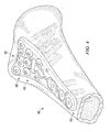
- FIGURE 1 generally demonstrates an embodiment of the volar plate 10, illustrating the basic shape and features generally associated with the present volar plate 10, while FIGURES 3A, 3B , 3C, and 3D further demonstrate the disclosed volar plate showing different views and bone screw placement.
- the volar plate of FIGURE 1 employs a generally Y-shaped plate 10, with a wider distal head portion 20 that tapers to a narrower proximal body portion 15. The distal head 20 angles upward away from the plane of the generally flat proximal body portion 15 of the volar plate, forming a concave upper surface 17. When the volar plate 10 is in place on the bone, the bottom surface 18 (which is opposite the upper surface) of the volar plate 10 would contact the bone. While the volar plate 10 could be constructed of any surgically safe material sufficiently strong and rigid to support bone fragments, the volar plate 10 of FIGURE 1 is generally made of medical grade anodized titanium or stainless steel.
- the Y-shaped volar plate 10 may vary in size, allowing the surgeon the option to select the volar plate 10 that best fits a particular patient.
- the volar plate 10 of the embodiment shown in FIGURE 1 might range in width, having a distal head portion 20 from approximately 20mm to 30mm across.
- the length of the volar plate 10 might range from approximately 45mm to 100mm.
- volar plates 10 tend to be 50mm to 65mm in length.
- the angle between the distal head 20 and the proximal body 15 is approximately twenty-five degrees. While specific disclosed embodiments may tend to have dimensions in the ranges discussed above, such dimensions are merely exemplary; a wide range of dimensions may be appropriate for the volar plate 10, and all are intended to be included within the scope of this disclosure.
- the shape of the volar plate 10 is designed to mimic and mesh with the bone surface geometry of the distal radius, as illustrated in FIGURE 2 .
- the Y-shape of the plate 10 allows for screw placement that essentially tracks the contours of the articular surface of the distal radius, basically following the subchondral bone contour line.
- the plate's shape provides anatomical alignment of the volar plate 10 within the pronator quadratus fossa, allowing bone screws to obtain purchase in the dorsal subchondral bone without danger of protrusion into the wrist joint space.
- volar surface geometry of the distal radius may not be standard, varying depending upon the individual.
- a crease 60 may score the bottom surface 18 of the corner of the distal head 20 of the volar plate 10 relating to the radial styloid, allowing the doctor to more easily bend that corner of the distal head portion 20 of the volar plate 10 to adjust the fit based on a particular patient's bone geometry.
- the prominence of the lunate facet may be variable, such that alternative embodiments may utilize a volar plate 10 with a curved distal end, with varying degrees of curvature laterally across the distal end of the volar plate, providing a high contour plate designed to align with greater protrusions of the lunate facet or a low contour plate for patients with less curvature along the pronator quadratus line.
- the embodiment of FIGURE 1 provides for a volar plate 10 designed to interact effectively with the patient's bone structure, thus providing a stable base of support for a wrist fracture.
- an anatomically designed volar plate 10 the risk of improper plate and screw placement is reduced, providing for successful, reproducible outcomes when mounting the volar plate 10 on the bone.
- the distal head 20 of the volar plate 10 for FIGURE 1 contains a plurality of threaded holes, through which bone screws (or some other fixation means) may be inserted to fix bone fragments in place relative to one another (as shown in FIGURE 3C ). While the volar plate 10 provides the underlying support, forming a steady base for affixing bone fragments, the bone screws 90 that screw into the threaded holes in the distal head 20 actually create the stabilization framework for the fracture. Generally, there are two rows of threaded screw holes located on the distal head 20 of the volar plate 10, and each of the holes are substantially the same size.
- Each row of screw holes shown in FIGURE 1 employs a substantially non-linear arrangement of holes, in an attempt to better match the contours of the wrist anatomy.
- the proximal row 40 of the volar plate 10 in FIGURE 1 has three threaded bone screw holes 41, 42, and 43 countersunk into the upper surface 17 of the volar plate 10.
- the volar plate 10 of FIGURE 1 utilizes a substantially non-linear alignment of the holes 41, 42, 43 in the proximal row 40, with the interior screw hole 42 distal to the two outside screw holes 41 and 43.
- the holes of proximal row 40 are staggered to essentially form a non-linear arc.
- the non-linear arc of the holes of the proximal row 40 proceeds from a proximal position, to a distal position, and back to a proximal position (generally forming a substantially parabolic arc).
- the proximal row 40 could form a non-linear arc that proceeds from a distal position, to a proximal position, and back to a distal position.
- Distal row 50 of FIGURE 1 has four threaded screw holes countersunk into the upper surface 17 of the volar plate 10. Again, the holes of the distal row 50 are arranged in a staggered, substantially non-linear alignment in an attempt to more closely match the contours of the distal radius, basically following the subchondral bone contour line in order to provide a stabilization framework that accommodates and interacts with the actual anatomy of the patient's wrist.
- the interior holes 52 and 53 of the distal row 50 of screw holes would be located proximal to the two outer screw holes 51 and 54, such that the holes of distal row 50 essentially form a non-linear (often parabolic-shaped) arc curving in the opposite direction of the arc of proximal row 40.
- distal row 50 curves from a distal position to a proximal position, and back to a distal position in the embodiment of FIGURE 1 .
- the holes of the distal row 50 could form a non-linear arc curving from a proximal position, to a distal position, and back to a proximal position.
- the non-linear orientation of the holes of the proximal and distal rows allows for a more organic design that may better interact with the underlying bone structure, such that the screws may track anatomical features and offer superior support.
- FIGURES 3A, 3B , 3C, and 3D illustrate one embodiment of the volar plate 10 with the bone screws 90 in place (screwed into the threaded holes in the volar plate 10), showing the projection of the shafts of the bone screws 90 out the bottom surface 18 of the head 20 of the volar plate 10.
- the distal row 50 of bone screws 90 would follow an angular orientation similar to the wrist joint surface, allowing the screws 90 to reach and obtain purchase in subchondral bone without entering the joint space, while the proximal row 40 of bone screws 90 would substantially converge on the distal row 50 of screws 90 to provide support while also possibly allowing the use of various screw lengths to accommodate various radius sizes, as necessary.
- the axes of the holes of the proximal row would substantially converge on the axes of the holes of the distal row, as both axes extend outward from the bottom surface of the volar plate.
- the term "converge” is intended here to describe the bone screws of the proximal row angling toward but not necessarily meeting or crossing the bone screws of the distal row in at least one plane.
- the screws 90 of the proximal row 40 would generally extend out between the screws 90 of the distal row 50.
- the screws 90 of the distal and proximal rows would typically be interleaved, creating an effective stabilization framework for bone fragments.
- Such an alignment would allow for bone fragments to be engaged by bone screws 90 from multiple directions, so that the bone screws 90 might essentially cradle each bone fragment and provide an improved stabilization framework for supporting the fracture site. It also might allow multiple smaller fragments to be properly positioned, since a multitude of support axes would be available. And it might allow screws of various sizes to be used, such that longer screws typically required for larger radius sizes would not interfere with each other.
- FIGURE 3D The bone screw 90 alignment of FIGURE 3D provides a detailed example.
- screws 90 in the distal row 50 project outward from the bottom surface 18 at an angle that can vary from substantially perpendicular to tilting towards the proximal end as they extend outward.
- the screws 90 may angle laterally as well.
- the outside screw 91 of the distal row 50 angles towards the proximal end of the volar plate 10, and may also simultaneously angle out away from the volar plate 10 laterally.
- the inside screw 92 (of the distal row) next to outside screw 91 angles towards the proximal end to a greater degree than does outside screw 91.
- the other inside screw 93 angles towards the proximal end less than both inside screw 92 and outside screw 91.
- the radial styloid screw 94 (which is the other outside screw corresponding to the corner of the head 20 of the volar plate 10 with a crease 60) is adjustable based on the position to which the corner is bent when fitting the volar plate 10 to the specific anatomical structure of the patient.
- the radial styloid screw 94 projects out to be substantially perpendicular to the bottom surface 18 of that corner of the head 20 of the volar plate10.
- the radial styloid screw 94 Since the corner of the head 20 of the volar plate 10 with the radial styloid 94 is typically flexed upward (such that the upper surface 17 of that corner is concave), the radial styloid screw 94 generally angles outward, allowing greater purchase of the typically larger radial styloid fragment.
- each of the bone screws 90 of the distal row 50 tend to angle towards the proximal end within a range of angles from approximately six degrees to thirty-two degrees from normal.
- each of the screws 90 of the distal row 50 may angle laterally (in either lateral direction) within a range of angles between approximately zero degrees and ten degrees (as measured from a vertical center plane). These ranges are merely exemplary, however; any number of bone screw 90 angles may be appropriate, and all are intended to be included within the scope of the disclosure.
- each of the seven threaded screw holes of the volar plate head 20 in this embodiment would generally be oriented so that the bone screws 90 inserted through them would project out in different directions, generally interleaving as the two rows converge.
- This provides for an effective stabilization framework, as bone fragments can be precisely held in the appropriate position in a manner that works with the underlying anatomical geometry of the distal radius.
- the precise bone screw placement described above for FIGURE 3D may vary, and different embodiments may use alternative placements.
- the general goal when placing bone screws 90 through a volar plate 10 is to provide an effective stabilization framework for fixing the bone fragments in proper alignment, preferably taking into account the anatomical geometry of the region.
- the volar plate 10 of the described embodiments also may contain a central cavity 70, located generally in the vicinity of the region of the volar plate 10 where the distal head 20 angles away from the proximal body 15.
- FIGURE 1 illustrates a central cavity 70.
- the central cavity 70 may promote bone growth by providing convenient access to proximal fracture sites for introduction of bone graft or bone void filler materials if needed during the treatment regimen.
- a plurality of mounting screw holes are located within the proximal body 15 of the volar plate 10, allowing for the plate to be mounted in place securely on the bone. Generally, the mounting screws would extend through the mounting screw holes substantially perpendicular to the bottom surface 18 of the body 15 of the volar plate.
- One or more mounting screw holes 31 are located towards the proximal end of the volar plate 10 (and one of these mounting screw holes could be configured as an elongated oval or slot 32, as shown in FIGURE 1 , allowing longitudinal movement of the volar plate 10 with respect to the shaft of the mounting screws for adjustment as the volar plate 10 is being affixed by the surgeon). These mounting screw holes allow the volar plate 10 to be firmly fixed in place on the bone using bone screws, providing a secure foundation for the stabilization framework. And in FIGURE 1 , two additional mounting screw holes 33 are distal to the proximal mounting screw holes 31 and the longitudinal slot 32, with one additional mounting screw hole 33 on either side of the central opening 70.
- These additional (distal) mounting screw holes 33 may provide for a more secure attachment of the volar plate 10 to the patient's bone and/or allow fixation and support of more proximal fractures. Because of the placement of the two additional (distal) mounting screw holes 33 about the central cavity 70, the central cavity 70 of FIGURE 1 is shaped to accommodate the screw placement by having a somewhat hourglass shape with a thinner waist in its middle. And given their distal position, it may be possible to utilize the additional (distal) mounting screws 33 to provide further support to the fracture site, in addition to possibly serving as additional mounting locations for secure attachment of the volar plate 10 to the bone. In this way, the distal mounting screw holes 33 may allow the volar plate 10 to address a wider range of fracture locations.
- all of the bone screw holes in the distal head 20, as well as the two distal mounting screws 33, are threaded. Utilizing threaded holes allows the bone screws 90 to be securely fastened to the volar plate 10, such that they may then hold bone fragments in position with respect to the volar plate 10. Thus, locking screws tend to be used in the distal head 20.
- Mounting holes 31 (and the longitudinal slot 32) are not threaded in FIGURE 1 , since the mounting screws do not need to attach (with engaging threads) to the volar plate 10, but can simply hold the volar plate 10 in position against the bone. Thus, non-locking screws tend to be used in the body.
- all of the holes for the bone screws used with the volar plate 10 are countersunk in the embodiment shown in FIGURE 1 . While this is not essential, it does provide a smoother upper surface 17, resulting in less irritation to the area surrounding the volar plate 10. And bone screws, with threading substantially along the length of their shafts, seem to provide a more secure stabilization framework, since they obtain purchase in the bone fragments.
- locking bone screws 90 are generally used within the distal head 20.
- the additional distal mounting screws (used within holes 33) may be either locking or non-locking, while the mounting screws (used within holes 31 and 32) tend to be non-locking.
- screws generally range from approximately 6mm to 28mm in length (depending upon the specific fracture situation).
- the diameter of the locking screws generally ranges from approximately 2mm to 2.7mm, while the non-locking screws (used for mounting the volar plate 10 to the bone) tend to be approximately 3.5mm in diameter.
- the volar plate 10 may include smaller holes for K-wires 80, allowing temporary fixation of the volar plate 10 in place during the surgical procedure in such a way that the surgeon may correctly position and temporarily fix the volar plate 10 prior to affixing it securely to the bone via bone screws.
- a plurality of K-wire holes 80 are positioned generally along the volar plate 10 in such a way as to allow for effective temporary placement of the volar plate during the mounting procedure.
- the volar plate 10 would be mounted directly to the volar surface of the distal radius bone during a surgical operation for aligning and fixing bone fragments of a wrist fracture.
- the bone screws may obtain purchase in the dorsal subchondral bone without danger of protrusion into the joint.
- the bottom face 18 of the volar plate 10 would be placed in contact with the bone, with the surgeon positioning the volar plate 10 as needed.
- the distal head portion 20 of the volar plate 10 would be placed over the bone fragments, so that bone screws 90 may be used to fix the position of the bone fragments.
- K-wires would be inserted through the guide holes 80 to temporarily fix the volar plate 10 onto the bone during the procedure and/or to provide an approximation of the projected axis of an adjacent screw position prior to actual insertion of the screw.
- the K-wires may also allow the surgeon to verify the approximate placement and angle that a screw may take in the bone. Since several of the K-wire holes 80 of the disclosed embodiment generally mimic the angle of nearby screw holes, the surgeon may preliminarily verify correct placement by examining the K-wire attachment to the bone via x-ray prior to drilling bone screw holes. The surgeon may then drill holes into the bone for the bone screws to enter and engage the bone.
- FIGURE 1 illustrates an exemplary volar plate 10 fixed in position with respect to the volar surface of the distal radius bone, with bone screws securing the volar plate and fixing the position of bone fragments.
- FIGURES 5, 6, and 7 illustrate alternative embodiments of the volar plate 10.
- FIGURE 5 for example, employs a central cavity 72, wherein the basic central cavity 70 of FIGURE 1 would be physically linked with the longitudinal mounting slot 32 of FIGURE 1 to form an elongated central cavity 72. This embodiment would allow maximum advantage from the central cavity 72, while also enhancing longitudinal adjustment capabilities.
- FIGURE 6 is similar, but the proximal body 15 is extended longitudinally, providing a longer volar plate 10 that can also accommodate shaft fractures.
- FIGURE 7 illustrates an embodiment in which the K-wire holes in the distal head 20 of the volar plate 10 are visually linked with their associated, corresponding bone screw holes.
- each of the seven threaded bone screw holes in the distal head 20 of this embodiment of the volar plate 10 project outward in different directions. It may be helpful for proper mounting if several of the K-wire holes in the distal head 20 would project outward in the same general direction as specific corresponding bone screw holes, such that the center-line axis of each K-wire hole in the distal head would be substantially parallel to the center-line axis of the corresponding bone screw hole. This type of orientation would aid the surgeon in properly aligning bone fragments with K-wires prior to final fixation with bone screws.
- FIGURE 7 illustrates an embodiment of the volar plate 10 in which K-wire hole 81 is visually linked with bone screw hole 52, while K-wire hole 82 is visually linked with bone screw hole 42.
Landscapes
- Health & Medical Sciences (AREA)
- Surgery (AREA)
- Orthopedic Medicine & Surgery (AREA)
- Life Sciences & Earth Sciences (AREA)
- Heart & Thoracic Surgery (AREA)
- Veterinary Medicine (AREA)
- Engineering & Computer Science (AREA)
- Biomedical Technology (AREA)
- Nuclear Medicine, Radiotherapy & Molecular Imaging (AREA)
- Medical Informatics (AREA)
- Molecular Biology (AREA)
- Animal Behavior & Ethology (AREA)
- General Health & Medical Sciences (AREA)
- Public Health (AREA)
- Pathology (AREA)
- Oral & Maxillofacial Surgery (AREA)
- Neurology (AREA)
- Surgical Instruments (AREA)
Claims (17)
- Eine volare Platte (10) bestehend aus:einem wesentlich flachen proximalen Körper (15); undeinem distalen Kopf (20), der mit dem proximalen Körper verbunden ist;wobei:der distale Kopf (20) breiter als der proximale Körper (15) ist;der distale Kopf (20) von der Ebene des proximalen Körpers nach oben abgewinkelt ist, wodurch eine wesentlich konkave obere Fläche (17) gebildet wird;im distalen Kopf (20) eine Vielzahl an Löchern gebildet ist;die Vielzahl der Löcher in zumindest zwei Reihen angeordnet ist, wobei eine proximale Reihe (40) mindestens drei Löcher (41, 42, 43) und eine distale Reihe (59) mindestens drei Löcher (51, 52, 53, 54) aufweist;die Löcher (41, 42, 43) der proximalen Reihe (40) wesentlich nicht linear angeordnet sind und die Löcher (51, 52, 53, 54) der distalen Reihe (50) wesentlich nicht linear angeordnet sind;die distale Reihe (50) ein oder mehrere interne Löcher (52, 53) und zwei äußere Löcher (51, 54) aufweist, wobei das eine oder die mehreren internen Löcher (52, 53) sich proximal zu den beiden äußeren Löchern (51, 54) befinden;die Löcher der distalen Reihe (50) alle distaler vom proximalen Körper als alle Löcher der proximalen Reihe positioniert sind; unddie proximale Reihe (40) an Löchern wesentlich einen parabolischen Bogen bildet, wobei die Position der Löcher der proximalen Reihe von einer proximalen Position zu einer distalen Position zu einer proximalen Position verläuft.
- Eine volare Platte entsprechend Anspruch 1, die zudem eines oder mehrere K-Draht-Löcher (80) im distalen Kopf (20) der volaren Platte aufweist, wobei:jedes K-Draht-Loch (80) einem der Vielzahl von Löchern im distalen Kopf der volaren Platte entspricht, wobei die Mittellinienachse jedes K-Draht-Lochs wesentlich parallel zur Mittellinienachse seines entsprechenden Lochs im distalen Kopf ist; undjedes K-Draht-Loch (80) visuell mit seinem entsprechenden Loch im distalen Kopf verbunden ist.
- Eine volare Platte entsprechend Anspruch 1, die zudem einen zentralen Hohlraum (70, 72) aufweist, wobei der zentrale Hohlraum wesentlich in Richtung des distalen Ende des proximalen Körpers (15) positioniert ist.
- Eine volare Platte entsprechend Anspruch 3, die zudem zwei Befestigungsschraubenlöcher (30) umfasst, wobei sich ein Befestigungsschraubenloch (33) lateral auf jeder Seite des zentralen Hohlraums (70) befindet.
- Eine volare Platte entsprechend Anspruch 1, wobei die proximale Reihe (40) ein oder mehrere innere Löcher (42) und zwei äußere Löcher (41, 43) umfasst, wobei das eine oder die mehreren internen Löcher (42) distal von den beiden äußeren Löchern (41, 43) sind.
- Eine volare Platte entsprechend Anspruch 1, wobei die distale Reihe der Löcher (50) einen wesentlich nicht linearen Bogen bildet, wobei die Position der Löcher der distalen Reihe von einer distalen Position zu einer proximalen Position zu einer distalen Position verläuft.
- Eine volare Platte entsprechend Anspruch 6, wobei die proximale Reihe (40) ein oder mehrere innere Löcher (42) und zwei äußere Löcher (41, 43) umfasst, wobei das eine oder die mehreren internen Löcher (42) der proximalen Reihe distal von den beiden äußeren Löchern (41, 43) der proximalen Reihe sind.
- Eine volare Platte entsprechend Anspruch 7, die zudem eine untere Fläche (18) aufweist, wobei die Vielzahl der Löcher im distalen Kopf (20) der volaren Platte so ausgerichtet sind, dass die Achsen der Löcher (51, 52, 53, 54) in der distalen Reihe (50) von der unteren Fläche (18) in einem Winkel proximal innerhalb einer Reihe von Winkeln von ca. 6 bis 32 Grad von der Normalen nach außen projizieren, und die Achsen der Löcher (41, 42, 43) in der proximalen Reihe (40) von der unteren Fläche (18) nach außen projizieren und wesentlich an den Achsen der Löcher der distalen Reihe konvergieren, während beide Achsen von der unteren Fläche der volaren Platte nach außen projizieren.
- Eine volare Platte entsprechend Anspruch 7, wobei die volare Platte wesentlich Y-Form aufweist.
- Eine volare Platte entsprechend Anspruch 7, die zudem einen Knick (60) entlang der unteren Fläche an einer Außenecke des distalen Kopfs (20) aufweist.
- Eine Fixiervorrichtung mit einer volaren Platte entsprechend einem der vorhergehenden Ansprüche und eine Vielzahl an Knochenschrauben (90) mit Gewindeschäften, wobei die Vielzahl der Löcher im distalen Kopf Gewinde haben und die Vielzahl der Knochenschrauben in den distalen Kopf (20) durch die Vielzahl der Gewindelöcher eindringen und dort verschraubt werden, so dass die Schäfte der Knochenschrauben von der unteren Fläche (18) der volaren Platte nach außen projizieren.
- Eine Fixiervorrichtung entsprechend Anspruch 11, wobei:die untere Fläche (18) der volaren Platte funktionsfähig ist, um mit der volaren Fläche eines Speichenknochens proximal zu einem Handgelenk in Kontakt gebracht werden kann; unddie Vielzahl der Löcher (41, 42, 43, 51, 52, 53, 54) im distalen Kopf der volaren Platte so ausgerichtet sind, dass die Schäfte der Knochenschrauben (90), die aus den Löchern (51, 52, 53, 54) der distalen Reihe (50) hervorstehen, nach außen von der unteren Fläche der volaren Platte verlaufen und allgemein auf die Gelenkfläche ausgerichtet sind, so dass in die subchondrale Knochenschicht eingegriffen wird und die Schäfte der Knochenschrauben (90), die aus den Löchern (41, 42, 43) der proximalen Reihe (40) hervorstehen, wesentlich an den Schäften der Knochenschrauben von der distalen Reihe konvergieren.
- Eine volare Platte entsprechend Anspruch 1, wobei die distale Reihe (50) von Löchern (51, 52, 53, 54) kurvenförmig verläuft, um wesentlich der Konturlinie des subchondralen Knochens eines distalen Speichenknochens zu folgen.
- Eine Fixiervorrichtung mit einer volaren Platte entsprechend Anspruch 1, und eine Vielzahl an Knochenschrauben (90) mit Gewindeschäften, wobei:die volare Platte eine untere Fläche (18) aufweist, die funktionsfähig ist, um mit der volaren Fläche eines Speichenknochens proximal zu einem Handgelenk in Kontakt gebracht werden kann;die Vielzahl der Knochenschraubendurch die Vielzahl der Gewindelöcher eindringen und so die volare Platte verschrauben, so dass die Schäfte der Knochenschrauben von der unteren Fläche der volaren Platte nach außen projizieren.die Vielzahl der Löcher im distalen Kopf der volaren Platte so ausgerichtet sind, dass die Schäfte der Knochenschrauben, die aus den Löchern der distalen Reihe hervorstehen, nach außen von der unteren Fläche der volaren Platte verlaufen und allgemein auf die Gelenkfläche ausgerichtet sind, so dass funktionsfähig in die subchondrale Knochenschicht eingegriffen wird und die Schäfte der Knochenschrauben, die aus den Löchern der proximalen Reihe hervorstehen, wesentlich an den Schäften der Knochenschrauben von der distalen Reihe konvergieren.
- Eine volare Platte entsprechend Anspruch 1 oder Anspruch 7 oder Anspruch 9 oder Anspruch 13, die die zudem eines oder mehrere K-Draht-Löcher (80) im distalen Kopf (20) der volaren Platte aufweist, wobei:jedes K-Draht-Loch (80) einem der Vielzahl von Gewindelöchern im distalen Kopf der volaren Platte entspricht, wobei die Mittellinienachse jedes K-Draht-Lochs wesentlich parallel zur Mittellinienachse seines entsprechenden Lochs im distalen Kopf ist; undjedes K-Draht-Loch (80) durch eine grafische Verbindung in der Fläche der volaren Platte mit seinem entsprechenden Gewindeloch im distalen Kopf verbunden ist.
- Eine volare Platte entsprechend Anspruch 1 oder eine Fixiervorrichtung entsprechend Anspruch 11, wobei die proximale und die distale Reihe von Gewindelöchern quer zu einer Längsachse der volaren Platte verlaufen und die nicht lineare Anordnung der Reihen durch Versetzung jedes Gewindelochs entlang der Längsachse der volaren Platte definiert ist.
- Eine volare Platte entsprechend Anspruch 1 oder eine Fixiervorrichtung entsprechend Anspruch 11, wobei der distale Kopf entlang der unteren Fläche einer Außenecke einen Knick aufweist.
Applications Claiming Priority (2)
| Application Number | Priority Date | Filing Date | Title |
|---|---|---|---|
| US11/567,661 US8398687B2 (en) | 2006-12-06 | 2006-12-06 | Volar plate fixation device |
| PCT/US2007/086450 WO2008070695A2 (en) | 2006-12-06 | 2007-12-05 | Volar plate fixation device |
Publications (3)
| Publication Number | Publication Date |
|---|---|
| EP2099373A2 EP2099373A2 (de) | 2009-09-16 |
| EP2099373A4 EP2099373A4 (de) | 2012-07-18 |
| EP2099373B1 true EP2099373B1 (de) | 2014-10-22 |
Family
ID=39493045
Family Applications (1)
| Application Number | Title | Priority Date | Filing Date |
|---|---|---|---|
| EP07854942.5A Active EP2099373B1 (de) | 2006-12-06 | 2007-12-05 | Volarplatten-fixiervorrichtung |
Country Status (6)
| Country | Link |
|---|---|
| US (1) | US8398687B2 (de) |
| EP (1) | EP2099373B1 (de) |
| AR (1) | AR064600A1 (de) |
| AU (1) | AU2007329398B2 (de) |
| ES (1) | ES2528203T3 (de) |
| WO (1) | WO2008070695A2 (de) |
Families Citing this family (46)
| Publication number | Priority date | Publication date | Assignee | Title |
|---|---|---|---|---|
| US8821508B2 (en) * | 2008-05-05 | 2014-09-02 | Trimed, Incorporated | Holder/impactor for contoured bone plate for fracture fixation |
| JP5634501B2 (ja) | 2009-05-05 | 2014-12-03 | シンセス ゲゼルシャフト ミット ベシュレンクテル ハフツングSynthes Gmbh | 釘係止システム |
| WO2011066280A1 (en) * | 2009-11-27 | 2011-06-03 | Synthes Usa, Llc | Plating concept for distal radial fractures |
| FR2956971B1 (fr) | 2010-03-08 | 2012-03-02 | Memometal Technologies | Systeme d'osteosynthese a plaque |
| FR2956972B1 (fr) | 2010-03-08 | 2012-12-28 | Memometal Technologies | Plaque d'osteosynthese articulee |
| US8603148B2 (en) * | 2010-05-07 | 2013-12-10 | Raymond B. Raven, III | System for treating bone fractures |
| KR101219266B1 (ko) * | 2010-08-13 | 2013-01-18 | 박지선 | 대퇴골 소전자와 주위를 견고하게 고정시켜서 인공 고관절 치환술이 가능할 수 있도록 안정적으로 보강하는 소전자 고정 장치 |
| WO2012050424A1 (en) * | 2010-10-14 | 2012-04-19 | Sai Yeong Leong | A distal radius plating system |
| US8518042B2 (en) * | 2010-10-19 | 2013-08-27 | Biomet Manufacturing, Llc | Orthopedic plate assembly for a distal radius having re-contouring features and method for using same |
| DE102010052231A1 (de) | 2010-11-24 | 2012-05-24 | Normed Medizin-Technik Gmbh | Medizinisches Implantat |
| US8790378B2 (en) | 2012-02-02 | 2014-07-29 | Biomet C.V. | Distal radius fracture fixation plate with integrated and adjustable volar ulnar facet support |
| EP2872073B1 (de) | 2012-07-12 | 2018-09-19 | Exsomed Holding Company LLC | Mittelhandknochenstabilisiereinrichtung |
| EP2730244B1 (de) * | 2012-11-07 | 2017-04-26 | Arthrex, Inc. | Knochenplatte mit Nahtlöchern zur Wiederanheftung von weichem Gewebe auf der Diaphyseregion der Platte |
| US9545276B2 (en) * | 2013-03-15 | 2017-01-17 | Aristotech Industries Gmbh | Fixation device and method of use for a lapidus-type plantar hallux valgus procedure |
| US11259849B2 (en) | 2013-10-02 | 2022-03-01 | ExsoMed Corporation | Full wrist fusion device |
| BR112016013208B1 (pt) * | 2013-12-11 | 2022-06-21 | Depuy Synthes Products, Inc | Placa óssea |
| US9848924B2 (en) | 2013-12-11 | 2017-12-26 | DePuy Synthes Products, Inc. | Bone plate |
| FR3023469B1 (fr) * | 2014-07-10 | 2016-08-26 | In2Bones | Implant et kit chirurgical pour maintenir en position des corps osseux d'un patient les uns par rapport aux autres |
| US9730686B2 (en) | 2014-09-03 | 2017-08-15 | Biomet C.V. | System and method of soft tissue anchoring to metaphyseal bone plate |
| AU2016205290B2 (en) | 2015-01-07 | 2020-11-26 | Treace Medical Concepts, Inc. | Bone plating system and method |
| US10245086B2 (en) | 2015-02-18 | 2019-04-02 | Treace Medical Concepts, Inc. | Bone plating kit for foot and ankle applications |
| US20160278824A1 (en) * | 2015-03-25 | 2016-09-29 | Medartis Holding Ag | Method for treating fractures of a bone |
| US10441330B2 (en) * | 2015-05-19 | 2019-10-15 | Exsomed Holding Company, Llc | Distal radius plate |
| US10245091B2 (en) | 2015-12-30 | 2019-04-02 | Exsomed Holding Company, Llc | Dip fusion spike screw |
| US11147604B2 (en) | 2016-01-12 | 2021-10-19 | ExsoMed Corporation | Bone stabilization device |
| USD787059S1 (en) * | 2016-02-17 | 2017-05-16 | Karl Leibinger Medzintechnik GmbH & Co. KG | Jawbone implant |
| USD786436S1 (en) * | 2016-02-17 | 2017-05-09 | Karl Leibinger Medizintechnik Gmbh & Co. Kg | Cheekbone implant |
| USD786435S1 (en) * | 2016-02-17 | 2017-05-09 | Karl Leibinger Medizintechnik Gmbh & Co. Kg | Jawbone implant |
| USD785798S1 (en) * | 2016-02-17 | 2017-05-02 | Karl Leibinger Medizintechnik Gmbh & Co. Kg | Jawbone implant |
| USD787060S1 (en) * | 2016-02-17 | 2017-05-16 | Karl Leibinger Medizintechnik Gmbh & Co. Kg | Jawbone implant |
| USD787058S1 (en) * | 2016-02-17 | 2017-05-16 | Karl Leibinger Medizintechnik Gmbh & Co. Kg | Eye-socket implant |
| USD785178S1 (en) * | 2016-02-17 | 2017-04-25 | Karl Leibinger Medizintechnik Gmbh & Co. Kg | Zygomatic bone implant |
| US10112062B2 (en) * | 2016-03-18 | 2018-10-30 | Fire Innovations Llc | Auto brake hand descent control device |
| US9956437B2 (en) * | 2016-03-18 | 2018-05-01 | Fire Innovations Llc | Auto brake hand descent control device |
| US10194923B2 (en) | 2016-05-10 | 2019-02-05 | Exsomed International IP, LLC | Tool for percutaneous joint cartilage destruction and preparation for joint fusion |
| USD869657S1 (en) | 2017-07-31 | 2019-12-10 | Crossroads Extremity Systems, Llc | Bone plate |
| US11147681B2 (en) | 2017-09-05 | 2021-10-19 | ExsoMed Corporation | Small bone angled compression screw |
| US11191645B2 (en) | 2017-09-05 | 2021-12-07 | ExsoMed Corporation | Small bone tapered compression screw |
| EP3678565A4 (de) | 2017-09-05 | 2021-10-27 | ExsoMed Corporation | Gewindemarknagel zur radialen kortikalisfixierung |
| CN111343934B (zh) | 2017-10-06 | 2023-06-30 | 布拉德·穆林 | 脊柱植入物 |
| CN111867504A (zh) | 2017-12-20 | 2020-10-30 | 格伦赫斯特实验室有限责任公司 | 用于骨折修复的多平面固定板 |
| US11583323B2 (en) | 2018-07-12 | 2023-02-21 | Treace Medical Concepts, Inc. | Multi-diameter bone pin for installing and aligning bone fixation plate while minimizing bone damage |
| USD874004S1 (en) * | 2018-09-26 | 2020-01-28 | Paragon 28, Inc. | Bone plate |
| USD874650S1 (en) * | 2018-10-23 | 2020-02-04 | DePuy Synthes Products, Inc. | Distal femur plate |
| US11877719B2 (en) * | 2019-06-25 | 2024-01-23 | OrthoNovis, Inc. | Bone plate with orientation indicator and positional adjustment mechanism |
| US11890039B1 (en) | 2019-09-13 | 2024-02-06 | Treace Medical Concepts, Inc. | Multi-diameter K-wire for orthopedic applications |
Family Cites Families (76)
| Publication number | Priority date | Publication date | Assignee | Title |
|---|---|---|---|---|
| AT378324B (de) * | 1982-09-13 | 1985-07-25 | Streli Elke | Zinkenplatte zur gegenseitigen lagefixierung der knochenteile bei knochenbruechen |
| US4776330A (en) * | 1986-06-23 | 1988-10-11 | Pfizer Hospital Products Group, Inc. | Modular femoral fixation system |
| US5190544A (en) * | 1986-06-23 | 1993-03-02 | Pfizer Hospital Products Group, Inc. | Modular femoral fixation system |
| US4905679A (en) * | 1988-02-22 | 1990-03-06 | M P Operation, Inc. | Bone fracture reduction device and method of internal fixation of bone fractures |
| US4955886A (en) * | 1988-04-01 | 1990-09-11 | The Trustees Of Columbia University In The City Of New York | Dual-taper, asymmetric hole placement in reconstruction and fracture plates |
| US5006120A (en) * | 1989-10-10 | 1991-04-09 | Carter Peter R | Distal radial fracture set and method for repairing distal radial fractures |
| US5015248A (en) * | 1990-06-11 | 1991-05-14 | New York Society For The Relief Of The Ruptured & Crippled, Maintaining The Hospital For Special Surgery | Bone fracture fixation device |
| US5085660A (en) * | 1990-11-19 | 1992-02-04 | Lin Kwan C | Innovative locking plate system |
| US5304180A (en) * | 1992-01-17 | 1994-04-19 | Slocum D Barclay | Tibial osteotomy fixation plate |
| US5197966A (en) * | 1992-05-22 | 1993-03-30 | Sommerkamp T Greg | Radiodorsal buttress blade plate implant for repairing distal radius fractures |
| IL105183A (en) * | 1993-03-28 | 1996-07-23 | Yehiel Gotfried | Surgical device for connection of fractured bones |
| SE501265C2 (sv) | 1993-05-07 | 1994-12-19 | Elos Ind Ab | Anordning för att fixera ryggkotor |
| DE4343117C2 (de) | 1993-12-17 | 1999-11-04 | Dietmar Wolter | Fixationssystem für Knochen |
| US5591169A (en) * | 1994-06-14 | 1997-01-07 | Benoist; Louis | Device and method for positioning and holding bone fragments in place |
| US5601553A (en) * | 1994-10-03 | 1997-02-11 | Synthes (U.S.A.) | Locking plate and bone screw |
| US5586985A (en) * | 1994-10-26 | 1996-12-24 | Regents Of The University Of Minnesota | Method and apparatus for fixation of distal radius fractures |
| SE505452C2 (sv) * | 1995-02-14 | 1997-09-01 | Robert J Medoff | En implanteringsbar fragmentklämma/stöd samt förfarande för framställning därav |
| SE508120C2 (sv) * | 1995-01-27 | 1998-08-31 | Robert J Medoff | Implanteringsbar anordning innefattande en stiftplatta och stift |
| SE505453C2 (sv) * | 1995-02-14 | 1997-09-01 | Robert J Medoff | Implanteringsbar stödplatta |
| US5941878A (en) * | 1995-02-14 | 1999-08-24 | Medoff; Robert J. | Implantable, surgical buttressing device |
| AU692846B2 (en) * | 1995-03-27 | 1998-06-18 | Synthes Gmbh | Bone plate |
| US5749872A (en) * | 1995-09-08 | 1998-05-12 | Ace Medical Company | Keyed/keyless barrel for bone plates |
| US5868749A (en) * | 1996-04-05 | 1999-02-09 | Reed; Thomas M. | Fixation devices |
| SE510025C2 (sv) * | 1996-05-10 | 1999-04-12 | Robert J Medoff | Fasthållningsanordning för graftmaterial |
| JP2000512186A (ja) | 1996-06-14 | 2000-09-19 | デピュイ エース メディカル カンパニー | 上肢骨プレート |
| US5827286A (en) * | 1997-02-14 | 1998-10-27 | Incavo; Stephen J. | Incrementally adjustable tibial osteotomy fixation device and method |
| US5853413A (en) * | 1997-04-18 | 1998-12-29 | Bristol-Myers Squibb Company | Wrist fusion plate |
| ZA983955B (en) * | 1997-05-15 | 2001-08-13 | Sdgi Holdings Inc | Anterior cervical plating system. |
| US6030389A (en) * | 1997-08-04 | 2000-02-29 | Spinal Concepts, Inc. | System and method for stabilizing the human spine with a bone plate |
| US6129728A (en) * | 1998-02-18 | 2000-10-10 | Walter Lorenz Surgical, Inc. | Method and apparatus for mandibular osteosynthesis |
| US5938664A (en) * | 1998-03-31 | 1999-08-17 | Zimmer, Inc. | Orthopaedic bone plate |
| US6228085B1 (en) * | 1998-07-14 | 2001-05-08 | Theken Surgical Llc | Bone fixation system |
| SE9900094D0 (sv) * | 1999-01-15 | 1999-01-15 | Robert J Medoff | A method of enabling bone screws to be installed at an angle in underlying bone |
| US6129730A (en) * | 1999-02-10 | 2000-10-10 | Depuy Acromed, Inc. | Bi-fed offset pitch bone screw |
| US6221073B1 (en) * | 1999-08-20 | 2001-04-24 | Kinetikos Medical, Inc. | Wrist fusion apparatus and method |
| ES2211583T3 (es) * | 1999-09-13 | 2004-07-16 | Synthes Ag Chur | Sistema de placa osea. |
| US6440135B2 (en) * | 2000-02-01 | 2002-08-27 | Hand Innovations, Inc. | Volar fixation system with articulating stabilization pegs |
| US6358250B1 (en) * | 2000-02-01 | 2002-03-19 | Hand Innovations, Inc. | Volar fixation system |
| US6893444B2 (en) * | 2000-02-01 | 2005-05-17 | Hand Innovations, Llc | Bone fracture fixation systems with both multidirectional and unidirectional stabilization pegs |
| US6712820B2 (en) * | 2000-02-01 | 2004-03-30 | Hand Innovations, Inc. | Fixation plate system for dorsal wrist fracture fixation |
| US6767351B2 (en) * | 2000-02-01 | 2004-07-27 | Hand Innovations, Inc. | Fixation system with multidirectional stabilization pegs |
| US6866665B2 (en) * | 2003-03-27 | 2005-03-15 | Hand Innovations, Llc | Bone fracture fixation system with subchondral and articular surface support |
| US6283969B1 (en) * | 2000-03-10 | 2001-09-04 | Wright Medical Technology, Inc. | Bone plating system |
| USD443060S1 (en) * | 2000-06-01 | 2001-05-29 | Bristol-Myers Squibb Company | Bone plate |
| US20020156474A1 (en) * | 2001-04-20 | 2002-10-24 | Michael Wack | Polyaxial locking plate |
| US20050049594A1 (en) * | 2001-04-20 | 2005-03-03 | Wack Michael A. | Dual locking plate and associated method |
| US7326212B2 (en) * | 2002-11-19 | 2008-02-05 | Acumed Llc | Bone plates with reference marks |
| US20050240187A1 (en) * | 2004-04-22 | 2005-10-27 | Huebner Randall J | Expanded fixation of bones |
| US20050234458A1 (en) * | 2004-04-19 | 2005-10-20 | Huebner Randall J | Expanded stabilization of bones |
| DK1389963T3 (da) * | 2001-05-28 | 2006-09-04 | Synthes Ag | Knogleplade til fiksering af proksimale humerusfrakturer |
| US6508819B1 (en) * | 2001-08-28 | 2003-01-21 | Hand Innovations, Inc. | Method of dorsal wrist fracture fixation |
| US6652530B2 (en) * | 2001-09-19 | 2003-11-25 | The University Of Hong Kong | Fixation device |
| US6755831B2 (en) * | 2001-11-30 | 2004-06-29 | Regents Of The University Of Minnesota | Wrist surgery devices and techniques |
| USD469533S1 (en) * | 2002-01-17 | 2003-01-28 | Zimmer, Inc. | Orthopaedic bone plate |
| US20030153918A1 (en) * | 2002-02-14 | 2003-08-14 | Putnam Matthew D. | Volar fixation plate |
| USD469874S1 (en) * | 2002-04-26 | 2003-02-04 | Zimmer, Inc. | Orthopaedic bone plate |
| US7635381B2 (en) * | 2003-03-27 | 2009-12-22 | Depuy Products, Inc. | Anatomical distal radius fracture fixation plate with fixed-angle K-wire holes defining a three-dimensional surface |
| US7250053B2 (en) * | 2003-03-27 | 2007-07-31 | Depuy Products, Inc. | Low profile distal radius fracture fixation plate |
| US7294130B2 (en) * | 2003-03-27 | 2007-11-13 | Depuy Products, Inc. | Distal radius fracture fixation plate having K-wire hole structured to fix a K-wire in one dimension relative to the plate |
| US20040193155A1 (en) * | 2003-03-27 | 2004-09-30 | Hand Innovations, Inc. | Fracture fixation plate with particular plate hole and fastener engagement and methods of using the same |
| EP1464295A3 (de) * | 2003-04-01 | 2006-04-26 | Zimmer GmbH | Implantat |
| EP1682020B1 (de) * | 2003-09-08 | 2007-10-17 | Synthes GmbH | Vorrichtung zur knochenfixation |
| US7269658B2 (en) | 2003-10-16 | 2007-09-11 | Lucent Technologies Inc. | Method and system for connecting calls through virtual media gateways |
| WO2005046494A1 (en) | 2003-10-17 | 2005-05-26 | Acumed Llc | Bone plates with slots |
| US20050085818A1 (en) * | 2003-10-17 | 2005-04-21 | Huebner Randall J. | Systems for distal radius fixation |
| CN103622741B (zh) * | 2004-01-23 | 2016-12-07 | 拜欧米特公司 | 用于包括软骨下支撑结构的凸状关节骨表面骨折的稳定系统 |
| US7572282B2 (en) * | 2004-04-23 | 2009-08-11 | Depuy Spine Sarl | Spinal fixation plates and plate extensions |
| US20060089648A1 (en) * | 2004-10-27 | 2006-04-27 | Masini Michael A | Versatile bone plate systems particularly suited to minimally invasive surgical procedures |
| US8062296B2 (en) * | 2005-03-17 | 2011-11-22 | Depuy Products, Inc. | Modular fracture fixation plate system with multiple metaphyseal and diaphyseal plates |
| US8172886B2 (en) * | 2004-12-14 | 2012-05-08 | Depuy Products, Inc. | Bone plate with pre-assembled drill guide tips |
| US7771433B2 (en) * | 2004-12-14 | 2010-08-10 | Depuy Products, Inc. | Bone fracture fixation plate shaping system |
| ES2300967T3 (es) * | 2005-03-11 | 2008-06-16 | Orthofix S.R.L. | Dispositivo para la osteosintesis de fracturas proximales del humero. |
| FI119969B (fi) * | 2005-05-06 | 2009-05-29 | Inion Ltd | Levy ja järjestelmä luuosien kiinnittämiseksi |
| US20060264947A1 (en) * | 2005-05-20 | 2006-11-23 | Orbay Jorge L | Bone fixation system |
| US8808334B2 (en) * | 2006-03-07 | 2014-08-19 | Orthohelix Surgical Designs, Inc. | Orthopedic plate |
| US8926675B2 (en) * | 2006-04-11 | 2015-01-06 | Biomet Manufacturing, Llc | Contoured bone plate |
-
2006
- 2006-12-06 US US11/567,661 patent/US8398687B2/en active Active
-
2007
- 2007-12-05 ES ES07854942.5T patent/ES2528203T3/es active Active
- 2007-12-05 AU AU2007329398A patent/AU2007329398B2/en active Active
- 2007-12-05 EP EP07854942.5A patent/EP2099373B1/de active Active
- 2007-12-05 WO PCT/US2007/086450 patent/WO2008070695A2/en active Application Filing
- 2007-12-06 AR ARP070105478A patent/AR064600A1/es not_active Application Discontinuation
Also Published As
| Publication number | Publication date |
|---|---|
| WO2008070695A2 (en) | 2008-06-12 |
| AR064600A1 (es) | 2009-04-15 |
| US8398687B2 (en) | 2013-03-19 |
| AU2007329398A1 (en) | 2008-06-12 |
| ES2528203T3 (es) | 2015-02-05 |
| US20080140127A1 (en) | 2008-06-12 |
| AU2007329398B2 (en) | 2013-06-20 |
| EP2099373A2 (de) | 2009-09-16 |
| EP2099373A4 (de) | 2012-07-18 |
| WO2008070695A3 (en) | 2008-07-31 |
Similar Documents
| Publication | Publication Date | Title |
|---|---|---|
| EP2099373B1 (de) | Volarplatten-fixiervorrichtung | |
| KR101144067B1 (ko) | 해부학적 원위 요골 골절 고정판 및 그 사용 방법 | |
| JP5547225B2 (ja) | 軟骨下関節表面支持体を備えた骨折固定システム | |
| JP4421474B2 (ja) | 長骨骨幹端骨折用の髄内固定デバイス | |
| US7563263B2 (en) | Intramedullary fixation device for metaphyseal long bone fractures | |
| US9370386B2 (en) | Plating concept for distal radial fractures | |
| US6730090B2 (en) | Fixation device for metaphyseal long bone fractures | |
| US20160166297A1 (en) | Bone plate with elevated suture hole structures | |
| ZA200602225B (en) | Anatomical distal radius fracture fixation plate and methods of using the same | |
| KR20020081282A (ko) | 장측 고정 장치 | |
| EP2675378A2 (de) | Bruchfixierungsplatte | |
| US11583317B2 (en) | Acromioclavicular hook plate | |
| EP3398545B1 (de) | Implantate zur behandlung von knöchelsyndesmose | |
| US20120016366A1 (en) | Proximal Radius Locking Plate | |
| US11446067B2 (en) | Distal radius plating system | |
| RU216558U1 (ru) | Устройство для остеосинтеза нестабильных переломов проксимального метаэпифиза большеберцовой кости |
Legal Events
| Date | Code | Title | Description |
|---|---|---|---|
| PUAI | Public reference made under article 153(3) epc to a published international application that has entered the european phase |
Free format text: ORIGINAL CODE: 0009012 |
|
| 17P | Request for examination filed |
Effective date: 20090608 |
|
| AK | Designated contracting states |
Kind code of ref document: A2 Designated state(s): AT BE BG CH CY CZ DE DK EE ES FI FR GB GR HU IE IS IT LI LT LU LV MC MT NL PL PT RO SE SI SK TR |
|
| DAX | Request for extension of the european patent (deleted) | ||
| A4 | Supplementary search report drawn up and despatched |
Effective date: 20120619 |
|
| RIC1 | Information provided on ipc code assigned before grant |
Ipc: A61B 17/80 20060101AFI20120613BHEP |
|
| 17Q | First examination report despatched |
Effective date: 20130409 |
|
| REG | Reference to a national code |
Ref country code: DE Ref legal event code: R079 Ref document number: 602007039004 Country of ref document: DE Free format text: PREVIOUS MAIN CLASS: A61B0017580000 Ipc: A61B0019000000 |
|
| GRAP | Despatch of communication of intention to grant a patent |
Free format text: ORIGINAL CODE: EPIDOSNIGR1 |
|
| RIC1 | Information provided on ipc code assigned before grant |
Ipc: A61B 17/80 20060101ALI20140505BHEP Ipc: A61B 19/00 20060101AFI20140505BHEP |
|
| INTG | Intention to grant announced |
Effective date: 20140522 |
|
| GRAS | Grant fee paid |
Free format text: ORIGINAL CODE: EPIDOSNIGR3 |
|
| GRAA | (expected) grant |
Free format text: ORIGINAL CODE: 0009210 |
|
| AK | Designated contracting states |
Kind code of ref document: B1 Designated state(s): AT BE BG CH CY CZ DE DK EE ES FI FR GB GR HU IE IS IT LI LT LU LV MC MT NL PL PT RO SE SI SK TR |
|
| REG | Reference to a national code |
Ref country code: GB Ref legal event code: FG4D |
|
| REG | Reference to a national code |
Ref country code: CH Ref legal event code: EP |
|
| REG | Reference to a national code |
Ref country code: AT Ref legal event code: REF Ref document number: 692227 Country of ref document: AT Kind code of ref document: T Effective date: 20141115 |
|
| REG | Reference to a national code |
Ref country code: IE Ref legal event code: FG4D |
|
| REG | Reference to a national code |
Ref country code: DE Ref legal event code: R096 Ref document number: 602007039004 Country of ref document: DE Effective date: 20141204 |
|
| REG | Reference to a national code |
Ref country code: ES Ref legal event code: FG2A Ref document number: 2528203 Country of ref document: ES Kind code of ref document: T3 Effective date: 20150205 |
|
| REG | Reference to a national code |
Ref country code: NL Ref legal event code: VDEP Effective date: 20141022 |
|
| REG | Reference to a national code |
Ref country code: AT Ref legal event code: MK05 Ref document number: 692227 Country of ref document: AT Kind code of ref document: T Effective date: 20141022 |
|
| REG | Reference to a national code |
Ref country code: LT Ref legal event code: MG4D |
|
| PG25 | Lapsed in a contracting state [announced via postgrant information from national office to epo] |
Ref country code: IS Free format text: LAPSE BECAUSE OF FAILURE TO SUBMIT A TRANSLATION OF THE DESCRIPTION OR TO PAY THE FEE WITHIN THE PRESCRIBED TIME-LIMIT Effective date: 20150222 Ref country code: NL Free format text: LAPSE BECAUSE OF FAILURE TO SUBMIT A TRANSLATION OF THE DESCRIPTION OR TO PAY THE FEE WITHIN THE PRESCRIBED TIME-LIMIT Effective date: 20141022 Ref country code: PT Free format text: LAPSE BECAUSE OF FAILURE TO SUBMIT A TRANSLATION OF THE DESCRIPTION OR TO PAY THE FEE WITHIN THE PRESCRIBED TIME-LIMIT Effective date: 20150223 Ref country code: LT Free format text: LAPSE BECAUSE OF FAILURE TO SUBMIT A TRANSLATION OF THE DESCRIPTION OR TO PAY THE FEE WITHIN THE PRESCRIBED TIME-LIMIT Effective date: 20141022 Ref country code: FI Free format text: LAPSE BECAUSE OF FAILURE TO SUBMIT A TRANSLATION OF THE DESCRIPTION OR TO PAY THE FEE WITHIN THE PRESCRIBED TIME-LIMIT Effective date: 20141022 |
|
| PG25 | Lapsed in a contracting state [announced via postgrant information from national office to epo] |
Ref country code: PL Free format text: LAPSE BECAUSE OF FAILURE TO SUBMIT A TRANSLATION OF THE DESCRIPTION OR TO PAY THE FEE WITHIN THE PRESCRIBED TIME-LIMIT Effective date: 20141022 Ref country code: SE Free format text: LAPSE BECAUSE OF FAILURE TO SUBMIT A TRANSLATION OF THE DESCRIPTION OR TO PAY THE FEE WITHIN THE PRESCRIBED TIME-LIMIT Effective date: 20141022 Ref country code: GR Free format text: LAPSE BECAUSE OF FAILURE TO SUBMIT A TRANSLATION OF THE DESCRIPTION OR TO PAY THE FEE WITHIN THE PRESCRIBED TIME-LIMIT Effective date: 20150123 Ref country code: AT Free format text: LAPSE BECAUSE OF FAILURE TO SUBMIT A TRANSLATION OF THE DESCRIPTION OR TO PAY THE FEE WITHIN THE PRESCRIBED TIME-LIMIT Effective date: 20141022 Ref country code: LV Free format text: LAPSE BECAUSE OF FAILURE TO SUBMIT A TRANSLATION OF THE DESCRIPTION OR TO PAY THE FEE WITHIN THE PRESCRIBED TIME-LIMIT Effective date: 20141022 Ref country code: CY Free format text: LAPSE BECAUSE OF FAILURE TO SUBMIT A TRANSLATION OF THE DESCRIPTION OR TO PAY THE FEE WITHIN THE PRESCRIBED TIME-LIMIT Effective date: 20141022 |
|
| PG25 | Lapsed in a contracting state [announced via postgrant information from national office to epo] |
Ref country code: BE Free format text: LAPSE BECAUSE OF NON-PAYMENT OF DUE FEES Effective date: 20141231 |
|
| REG | Reference to a national code |
Ref country code: DE Ref legal event code: R097 Ref document number: 602007039004 Country of ref document: DE |
|
| PG25 | Lapsed in a contracting state [announced via postgrant information from national office to epo] |
Ref country code: CZ Free format text: LAPSE BECAUSE OF FAILURE TO SUBMIT A TRANSLATION OF THE DESCRIPTION OR TO PAY THE FEE WITHIN THE PRESCRIBED TIME-LIMIT Effective date: 20141022 Ref country code: SK Free format text: LAPSE BECAUSE OF FAILURE TO SUBMIT A TRANSLATION OF THE DESCRIPTION OR TO PAY THE FEE WITHIN THE PRESCRIBED TIME-LIMIT Effective date: 20141022 Ref country code: EE Free format text: LAPSE BECAUSE OF FAILURE TO SUBMIT A TRANSLATION OF THE DESCRIPTION OR TO PAY THE FEE WITHIN THE PRESCRIBED TIME-LIMIT Effective date: 20141022 Ref country code: RO Free format text: LAPSE BECAUSE OF FAILURE TO SUBMIT A TRANSLATION OF THE DESCRIPTION OR TO PAY THE FEE WITHIN THE PRESCRIBED TIME-LIMIT Effective date: 20141022 Ref country code: DK Free format text: LAPSE BECAUSE OF FAILURE TO SUBMIT A TRANSLATION OF THE DESCRIPTION OR TO PAY THE FEE WITHIN THE PRESCRIBED TIME-LIMIT Effective date: 20141022 Ref country code: LU Free format text: LAPSE BECAUSE OF FAILURE TO SUBMIT A TRANSLATION OF THE DESCRIPTION OR TO PAY THE FEE WITHIN THE PRESCRIBED TIME-LIMIT Effective date: 20141205 |
|
| REG | Reference to a national code |
Ref country code: CH Ref legal event code: PL |
|
| PLBE | No opposition filed within time limit |
Free format text: ORIGINAL CODE: 0009261 |
|
| STAA | Information on the status of an ep patent application or granted ep patent |
Free format text: STATUS: NO OPPOSITION FILED WITHIN TIME LIMIT |
|
| REG | Reference to a national code |
Ref country code: IE Ref legal event code: MM4A |
|
| 26N | No opposition filed |
Effective date: 20150723 |
|
| PG25 | Lapsed in a contracting state [announced via postgrant information from national office to epo] |
Ref country code: LI Free format text: LAPSE BECAUSE OF NON-PAYMENT OF DUE FEES Effective date: 20141231 Ref country code: CH Free format text: LAPSE BECAUSE OF NON-PAYMENT OF DUE FEES Effective date: 20141231 Ref country code: IE Free format text: LAPSE BECAUSE OF NON-PAYMENT OF DUE FEES Effective date: 20141205 |
|
| REG | Reference to a national code |
Ref country code: FR Ref legal event code: PLFP Year of fee payment: 9 |
|
| PG25 | Lapsed in a contracting state [announced via postgrant information from national office to epo] |
Ref country code: SI Free format text: LAPSE BECAUSE OF FAILURE TO SUBMIT A TRANSLATION OF THE DESCRIPTION OR TO PAY THE FEE WITHIN THE PRESCRIBED TIME-LIMIT Effective date: 20141022 |
|
| PG25 | Lapsed in a contracting state [announced via postgrant information from national office to epo] |
Ref country code: BG Free format text: LAPSE BECAUSE OF FAILURE TO SUBMIT A TRANSLATION OF THE DESCRIPTION OR TO PAY THE FEE WITHIN THE PRESCRIBED TIME-LIMIT Effective date: 20141022 Ref country code: MC Free format text: LAPSE BECAUSE OF FAILURE TO SUBMIT A TRANSLATION OF THE DESCRIPTION OR TO PAY THE FEE WITHIN THE PRESCRIBED TIME-LIMIT Effective date: 20141022 |
|
| PG25 | Lapsed in a contracting state [announced via postgrant information from national office to epo] |
Ref country code: HU Free format text: LAPSE BECAUSE OF FAILURE TO SUBMIT A TRANSLATION OF THE DESCRIPTION OR TO PAY THE FEE WITHIN THE PRESCRIBED TIME-LIMIT; INVALID AB INITIO Effective date: 20071205 Ref country code: MT Free format text: LAPSE BECAUSE OF FAILURE TO SUBMIT A TRANSLATION OF THE DESCRIPTION OR TO PAY THE FEE WITHIN THE PRESCRIBED TIME-LIMIT Effective date: 20141022 |
|
| REG | Reference to a national code |
Ref country code: FR Ref legal event code: PLFP Year of fee payment: 10 |
|
| REG | Reference to a national code |
Ref country code: FR Ref legal event code: PLFP Year of fee payment: 11 |
|
| REG | Reference to a national code |
Ref country code: DE Ref legal event code: R082 Ref document number: 602007039004 Country of ref document: DE Representative=s name: PATENTANWAELTE BAUER VORBERG KAYSER PARTNERSCH, DE Ref country code: DE Ref legal event code: R081 Ref document number: 602007039004 Country of ref document: DE Owner name: ORTHOFIX S.R.L., IT Free format text: FORMER OWNER: AMEI TECHNOLOGIES INC., WILMINGTON, DEL., US Ref country code: DE Ref legal event code: R081 Ref document number: 602007039004 Country of ref document: DE Owner name: ORTHOFIX S.R.L., BUSSOLENGO, IT Free format text: FORMER OWNER: AMEI TECHNOLOGIES INC., WILMINGTON, DEL., US |
|
| REG | Reference to a national code |
Ref country code: DE Ref legal event code: R081 Ref document number: 602007039004 Country of ref document: DE Owner name: ORTHOFIX S.R.L., BUSSOLENGO, IT Free format text: FORMER OWNER: ORTHOFIX S.R.L., MILANO, IT Ref country code: DE Ref legal event code: R082 Ref document number: 602007039004 Country of ref document: DE Representative=s name: PATENTANWAELTE BAUER VORBERG KAYSER PARTNERSCH, DE |
|
| REG | Reference to a national code |
Ref country code: ES Ref legal event code: PC2A Owner name: ORTHOFIX S.R.L. Effective date: 20181218 |
|
| REG | Reference to a national code |
Ref country code: GB Ref legal event code: 732E Free format text: REGISTERED BETWEEN 20210930 AND 20211006 |
|
| PGFP | Annual fee paid to national office [announced via postgrant information from national office to epo] |
Ref country code: TR Payment date: 20221124 Year of fee payment: 16 Ref country code: IT Payment date: 20221122 Year of fee payment: 16 |
|
| P01 | Opt-out of the competence of the unified patent court (upc) registered |
Effective date: 20230517 |
|
| PGFP | Annual fee paid to national office [announced via postgrant information from national office to epo] |
Ref country code: GB Payment date: 20231121 Year of fee payment: 17 |
|
| PGFP | Annual fee paid to national office [announced via postgrant information from national office to epo] |
Ref country code: FR Payment date: 20231122 Year of fee payment: 17 Ref country code: DE Payment date: 20231121 Year of fee payment: 17 |
|
| PGFP | Annual fee paid to national office [announced via postgrant information from national office to epo] |
Ref country code: ES Payment date: 20240102 Year of fee payment: 17 |