EP2098148A2 - Trennwand mit Gelenkband und Gelenkband für eine Trennwand - Google Patents
Trennwand mit Gelenkband und Gelenkband für eine Trennwand Download PDFInfo
- Publication number
- EP2098148A2 EP2098148A2 EP09001734A EP09001734A EP2098148A2 EP 2098148 A2 EP2098148 A2 EP 2098148A2 EP 09001734 A EP09001734 A EP 09001734A EP 09001734 A EP09001734 A EP 09001734A EP 2098148 A2 EP2098148 A2 EP 2098148A2
- Authority
- EP
- European Patent Office
- Prior art keywords
- hinge
- recess
- wing
- wall
- door
- Prior art date
- Legal status (The legal status is an assumption and is not a legal conclusion. Google has not performed a legal analysis and makes no representation as to the accuracy of the status listed.)
- Granted
Links
- 238000005192 partition Methods 0.000 title claims description 57
- 239000011521 glass Substances 0.000 claims abstract description 5
- 238000007789 sealing Methods 0.000 claims description 78
- 230000002093 peripheral effect Effects 0.000 claims description 12
- 239000005336 safety glass Substances 0.000 claims description 4
- 210000002414 leg Anatomy 0.000 description 7
- 210000000689 upper leg Anatomy 0.000 description 4
- 240000001439 Opuntia Species 0.000 description 2
- 235000004727 Opuntia ficus indica Nutrition 0.000 description 2
- 238000011161 development Methods 0.000 description 2
- 230000018109 developmental process Effects 0.000 description 2
- 210000000707 wrist Anatomy 0.000 description 2
- 238000004026 adhesive bonding Methods 0.000 description 1
- 238000013459 approach Methods 0.000 description 1
- 230000006835 compression Effects 0.000 description 1
- 238000007906 compression Methods 0.000 description 1
- 230000001419 dependent effect Effects 0.000 description 1
- 230000000694 effects Effects 0.000 description 1
- 230000003993 interaction Effects 0.000 description 1
- 238000004519 manufacturing process Methods 0.000 description 1
- 238000000465 moulding Methods 0.000 description 1
- 239000007921 spray Substances 0.000 description 1
- XLYOFNOQVPJJNP-UHFFFAOYSA-N water Substances O XLYOFNOQVPJJNP-UHFFFAOYSA-N 0.000 description 1
Images


Classifications
-
- A—HUMAN NECESSITIES
- A47—FURNITURE; DOMESTIC ARTICLES OR APPLIANCES; COFFEE MILLS; SPICE MILLS; SUCTION CLEANERS IN GENERAL
- A47K—SANITARY EQUIPMENT NOT OTHERWISE PROVIDED FOR; TOILET ACCESSORIES
- A47K3/00—Baths; Douches; Appurtenances therefor
- A47K3/28—Showers or bathing douches
- A47K3/30—Screens or collapsible cabinets for showers or baths
- A47K3/36—Articulated screens
-
- E—FIXED CONSTRUCTIONS
- E05—LOCKS; KEYS; WINDOW OR DOOR FITTINGS; SAFES
- E05D—HINGES OR SUSPENSION DEVICES FOR DOORS, WINDOWS OR WINGS
- E05D5/00—Construction of single parts, e.g. the parts for attachment
- E05D5/02—Parts for attachment, e.g. flaps
- E05D5/0246—Parts for attachment, e.g. flaps for attachment to glass panels
-
- E—FIXED CONSTRUCTIONS
- E05—LOCKS; KEYS; WINDOW OR DOOR FITTINGS; SAFES
- E05F—DEVICES FOR MOVING WINGS INTO OPEN OR CLOSED POSITION; CHECKS FOR WINGS; WING FITTINGS NOT OTHERWISE PROVIDED FOR, CONCERNED WITH THE FUNCTIONING OF THE WING
- E05F1/00—Closers or openers for wings, not otherwise provided for in this subclass
- E05F1/02—Closers or openers for wings, not otherwise provided for in this subclass gravity-actuated, e.g. by use of counterweights
- E05F1/04—Closers or openers for wings, not otherwise provided for in this subclass gravity-actuated, e.g. by use of counterweights for wings which lift during movement, operated by their own weight
- E05F1/06—Mechanisms in the shape of hinges or pivots, operated by the weight of the wing
- E05F1/061—Mechanisms in the shape of hinges or pivots, operated by the weight of the wing with cams or helical tracks
-
- A—HUMAN NECESSITIES
- A47—FURNITURE; DOMESTIC ARTICLES OR APPLIANCES; COFFEE MILLS; SPICE MILLS; SUCTION CLEANERS IN GENERAL
- A47K—SANITARY EQUIPMENT NOT OTHERWISE PROVIDED FOR; TOILET ACCESSORIES
- A47K3/00—Baths; Douches; Appurtenances therefor
- A47K3/28—Showers or bathing douches
- A47K3/30—Screens or collapsible cabinets for showers or baths
- A47K3/36—Articulated screens
- A47K2003/367—Hinges urging the articulated screen in one or more stable positions
-
- E—FIXED CONSTRUCTIONS
- E05—LOCKS; KEYS; WINDOW OR DOOR FITTINGS; SAFES
- E05D—HINGES OR SUSPENSION DEVICES FOR DOORS, WINDOWS OR WINGS
- E05D5/00—Construction of single parts, e.g. the parts for attachment
- E05D5/02—Parts for attachment, e.g. flaps
- E05D5/0246—Parts for attachment, e.g. flaps for attachment to glass panels
- E05D2005/0253—Parts for attachment, e.g. flaps for attachment to glass panels the panels having conical or stepped recesses
-
- E—FIXED CONSTRUCTIONS
- E05—LOCKS; KEYS; WINDOW OR DOOR FITTINGS; SAFES
- E05D—HINGES OR SUSPENSION DEVICES FOR DOORS, WINDOWS OR WINGS
- E05D5/00—Construction of single parts, e.g. the parts for attachment
- E05D5/02—Parts for attachment, e.g. flaps
- E05D5/0246—Parts for attachment, e.g. flaps for attachment to glass panels
- E05D2005/0261—Parts for attachment, e.g. flaps for attachment to glass panels connecting two or more glass panels
- E05D2005/0269—Parts for attachment, e.g. flaps for attachment to glass panels connecting two or more glass panels the panels being coplanar
-
- E—FIXED CONSTRUCTIONS
- E05—LOCKS; KEYS; WINDOW OR DOOR FITTINGS; SAFES
- E05Y—INDEXING SCHEME ASSOCIATED WITH SUBCLASSES E05D AND E05F, RELATING TO CONSTRUCTION ELEMENTS, ELECTRIC CONTROL, POWER SUPPLY, POWER SIGNAL OR TRANSMISSION, USER INTERFACES, MOUNTING OR COUPLING, DETAILS, ACCESSORIES, AUXILIARY OPERATIONS NOT OTHERWISE PROVIDED FOR, APPLICATION THEREOF
- E05Y2800/00—Details, accessories and auxiliary operations not otherwise provided for
- E05Y2800/10—Additional functions
- E05Y2800/12—Sealing
-
- E—FIXED CONSTRUCTIONS
- E05—LOCKS; KEYS; WINDOW OR DOOR FITTINGS; SAFES
- E05Y—INDEXING SCHEME ASSOCIATED WITH SUBCLASSES E05D AND E05F, RELATING TO CONSTRUCTION ELEMENTS, ELECTRIC CONTROL, POWER SUPPLY, POWER SIGNAL OR TRANSMISSION, USER INTERFACES, MOUNTING OR COUPLING, DETAILS, ACCESSORIES, AUXILIARY OPERATIONS NOT OTHERWISE PROVIDED FOR, APPLICATION THEREOF
- E05Y2800/00—Details, accessories and auxiliary operations not otherwise provided for
- E05Y2800/15—Applicability
- E05Y2800/16—Applicable on combinations of fixed and movable wings
- E05Y2800/162—Applicable on combinations of fixed and movable wings the wings being coplanar when the movable wing is in the closed position
-
- E—FIXED CONSTRUCTIONS
- E05—LOCKS; KEYS; WINDOW OR DOOR FITTINGS; SAFES
- E05Y—INDEXING SCHEME ASSOCIATED WITH SUBCLASSES E05D AND E05F, RELATING TO CONSTRUCTION ELEMENTS, ELECTRIC CONTROL, POWER SUPPLY, POWER SIGNAL OR TRANSMISSION, USER INTERFACES, MOUNTING OR COUPLING, DETAILS, ACCESSORIES, AUXILIARY OPERATIONS NOT OTHERWISE PROVIDED FOR, APPLICATION THEREOF
- E05Y2800/00—Details, accessories and auxiliary operations not otherwise provided for
- E05Y2800/26—Form or shape
- E05Y2800/27—Profiles; Strips
-
- E—FIXED CONSTRUCTIONS
- E05—LOCKS; KEYS; WINDOW OR DOOR FITTINGS; SAFES
- E05Y—INDEXING SCHEME ASSOCIATED WITH SUBCLASSES E05D AND E05F, RELATING TO CONSTRUCTION ELEMENTS, ELECTRIC CONTROL, POWER SUPPLY, POWER SIGNAL OR TRANSMISSION, USER INTERFACES, MOUNTING OR COUPLING, DETAILS, ACCESSORIES, AUXILIARY OPERATIONS NOT OTHERWISE PROVIDED FOR, APPLICATION THEREOF
- E05Y2800/00—Details, accessories and auxiliary operations not otherwise provided for
- E05Y2800/26—Form or shape
- E05Y2800/292—Form or shape having apertures
-
- E—FIXED CONSTRUCTIONS
- E05—LOCKS; KEYS; WINDOW OR DOOR FITTINGS; SAFES
- E05Y—INDEXING SCHEME ASSOCIATED WITH SUBCLASSES E05D AND E05F, RELATING TO CONSTRUCTION ELEMENTS, ELECTRIC CONTROL, POWER SUPPLY, POWER SIGNAL OR TRANSMISSION, USER INTERFACES, MOUNTING OR COUPLING, DETAILS, ACCESSORIES, AUXILIARY OPERATIONS NOT OTHERWISE PROVIDED FOR, APPLICATION THEREOF
- E05Y2900/00—Application of doors, windows, wings or fittings thereof
- E05Y2900/10—Application of doors, windows, wings or fittings thereof for buildings or parts thereof
- E05Y2900/114—Application of doors, windows, wings or fittings thereof for buildings or parts thereof for showers
Definitions
- the invention relates to a partition, in particular shower partition, comprising a wall element and a door element and at least one hinge according to the preamble of claim 1 and a hinge according to the preamble of claim 15.
- a partition which comprises a wall element, a door element and at least one hinge, wherein the door element is rotatably mounted in particular by means of two hinge bands on the wall element, each hinge having a first and a second wing, wherein the wall element and the door element with Opposite longitudinal edges, wherein each hinge band is associated with a recess which is formed on the longitudinal edge of the wall member or the door member, wherein the first wing and the second wing of the hinge band engage in the recess and wherein the two wings are rotatably connected to each other about an axis of rotation.
- a disadvantage of such partitions is that, in particular, when the partition wall has a arranged on the door element to a bottom and / or arranged on the bottom seal, the closing and opening is difficult and reduces the life of the seal or seals due to heavy wear.
- the invention has for its object to develop a partition which, despite an arrangement of the hinge in a recess of the wall element or the door member allows a low-resistance opening and closing of the door element and ensures a splash-proof in the recess in particular when the door element is closed. Furthermore, it is an object of the invention to develop a hinge which is adaptable to changing space in the region of its axis of rotation.
- a rotational movement of the door member relative to the wall element is superimposed by an axial movement of the door member in the direction of the axis of rotation, wherein the axial movement can be generated by the cooperating wings of the hinge and wherein a recess in their Dimensions is dimensioned such that the arranged on the door element wings of the hinge in the recess between a lowered position and a raised position in the direction of the axis of rotation is movable.
- the invention provides, in a free space, which in the recess between the hinge and the wall element or the door element is formed to arrange at least one sealing element.
- the invention provides a relative mobility and / or deformability of the first sealing element with respect to at least one peripheral edge of the cutout. As a result, obstruction of the lifting-lowering and rotational movement of the door element is avoided by the first sealing element, since this is adaptable in its position and / or in its shape to the existing in the respective rotational position of the door element requirements.
- the first sealing element is attached to one of the wings of the hinge, wherein the first sealing element is in particular rotatably attached to this wing of the hinge and wherein the first sealing element is in particular rotatably mounted around the axis of rotation of the hinge to this wing of the hinge.
- a variant of the invention provides to provide the wall element with the recess and to secure the first sealing element to the movable wing of the hinge band which is associated with the door element, wherein the sealing element with the movable wing relative to the wall element upon rotation of the door member about the axis of rotation movable in the axial direction relative to the wall element and / or deformable by the movable wing of the hinge.
- a further embodiment provides to arrange the recess in the door member and to secure the first sealing element to the stationary wing of the hinge band, which is associated with the wall element, wherein the door element is rotatable relative to the sealing element in rotation about the axis of rotation and / / or deformable by the door element.
- This makes it possible for the door element is by sliding in the first sealing element and / or compressing or stretching the first sealing element when opening the door element with the wing, which is associated with the door element, upwards in the direction of the axis of rotation relative to the wing, which is assigned to the edge element to lift.
- the invention provides for the first sealing element to be formed by an L-shaped component as a profile, which in particular has a U-shaped cross section at least on one leg and, with its webs as a rider, overlaps an edge of the recess.
- a sealing element is easy to manufacture and can be safely without further components on the wall element or the door element.
- a second sealing element in the recess, which is in particular formed as an L-shaped profile and in particular at least on one leg has a U-shaped cross-section and with this as a rider at least one edge of the recess with two webs overlaps.
- a second sealing element is easy to install without gluing, since it is held in the recess between one of the wings and the wall element or the door element.
- the invention provides, to screw the axially stationary wings of the hinge and / or the axially movable wings of the hinge by means of conical discs with internal thread or set screw flush with countersunk holes of the wall element or the door element.
- the invention also provides a hinge which is designed as a lifting-lowering hinge and has on one of its wings a first sealing element which is connected to this wing. This makes it possible by means of the hinge band to control the movement of a sealing element and so to position the sealing element depending on a rotational position of the hinge.
- a wall element is understood to be an element which is formed, in particular, by a plate fixedly mounted in a room, this plate being designed in particular as a glass plate.
- the wall element may also be designed as a fixed wall or wall.
- a hinge is understood to be a hinge or a hinge, by means of which two components can be connected to one another in a rotatable manner.
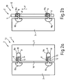
- the partition wall 1 is designed as a shower partition wall 2 and comprises a fixed wall element 3 and a relative to the wall element 3 rotatable about a rotation axis d door element 4.
- the wall element 3 has two recesses 5, 6, which on a formed vertically in space longitudinal edge 7 of the wall element 3 are formed.
- the wall element 3 and the door element 4 are interconnected via hinge bands 8, 9.
- the hinge bands 8, 9 each consist of a first wing 8a and 9a, which is connected to the door element 4 and a second wing 8b and 9b, which is connected to the wall element 3.
- the wings 8a, 8b and 9a, 9b are rotatably connected to each other in the recess 5 or in the recess 6 about the already mentioned rotation axis d.
- the hinge 8 and the hinge 9 are in a known manner as so-called lifting-lowering joints 10th executed, in which a measured in the direction of the rotation axis d distance between the wings 8a and 8b or 9a and 9b by a rotation of the first wing 8a and 9a relative to the second wing 8b and 9b from a distance a (see FIG. 1a ) to a distance A (see FIG. 1b ) changed by the interaction of moldings, not shown.
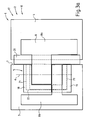
- FIGS. 2a and 2b is a simplified representation of a second partition 13 is shown.
- the second partition wall 13 is also designed as a shower partition wall 2 and comprises a wall element 3 and a door element 4, which are connected via hinge bands 8 and 9, wherein, in contrast to the in the FIGS. 1a and 1b shown first partition wall recesses 14 and 15 are not arranged on the wall element 3, but on a longitudinal edge 16 of the door element 4.
- the hinge bands 8 and 9 each comprise two wings 8a, 8b and 9a, 9b, which are rotatably connected to each other about a rotation axis d in the recess 14 and the recess 15.
- the hinge bands 8 and 9 are in turn designed as a so-called lifting-lowering joints 10. In one in the FIG.
- the recesses 14, 15 respectively below the hinge bands 8 and 9 free spaces 11 and 12, respectively.
- the door element 4 When opening the door element 4 from in the FIG. 2a shown lowered position I in one in the FIG. 2b shown raised position II, the door element 4 is lifted by the wings 8a and 9a in an arrow direction y in the direction of the axis of rotation d, thereby entering the free spaces 11 and 12, respectively.
- the free spaces 11, 12 are closed by in each case at least one sealing element, the display of sealing elements being omitted here for the sake of clarity.
- FIG. 3a is a detailed view of a third partition wall 17 is shown, wherein the third partition 17 with respect to its basic structure with in the FIGS. 1a and 1b
- a wall element 3 has a recess 5, which is arranged on a longitudinal edge 7 of the wall element 3.
- the Indian FIG. 3a shown section of the partition 17 is part of a shower partition 2, which also otherwise comparable to that in the FIGS. 1a and 1b is shown, and in which a door element 4 is also fastened by means of two hinge bands on the wall element 3, wherein in the FIG. 3a only the upper hinge 8 is shown.
- the hinge 8 comprises a first wing 8 a, which is fixed to the door member 4, and a second wing 8 b, which is fixed to the wall element 3.
- the wings 8a and 8b of the hinge 8 are connected to each other in the recess 5 and have an axis of rotation d with each other, which runs parallel to the longitudinal edge 7 of the wall element 3.
- the hinge 8 is as a so-called lifting-lowering joint 10th executed.
- the third partition wall 17 comprises, in addition to the wall element 3, the door element 4 and the hinge 8, a first sealing element 18, a second sealing element 19 and a conventional door seal 20, which is fastened to the door element 4.
- In the FIG. 3a is the hinge I or the door element 4 in a lowered position I, in which the door element 4 is closed. In this lowered position I, the recess 5 is closed in the wall element 3 by the wings 8a and 8b and the two sealing elements 18 and 19 or sealed against spray water. With dashed lines edge edges 21, 22 and 23 are indicated, which limit the
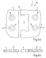
- FIG. 3b are as individual parts of the FIG. 3a the wall element 3 with its recess 5, the first sealing element 18 and the second sealing element 19 shown.
- the recess 5 is bounded by the already mentioned marginal edges 21 to 23.
- the wall element 3 is preferably made of safety glass.
- the first sealing element 18 is formed by an L-shaped profile 24, which has two legs 25, 26.
- the two legs 25, 26 each have a U-shaped cross-section (see also FIG. 3g ). With dashed lines groove bottoms 25a and 25b indicated, which arise through this U-shaped cross-section.
- the first sealing element 18 forms a tab 27, which can be placed on the wall element 3 in the region of the cutout 5.
- the second sealing element 19 is likewise designed as an L-shaped profile 28, which has two legs 29 and 30.
- These two legs 29, 30 each have a U-shaped cross-section.
- the second sealing element 19 also forms a tab 31, which can be pushed onto the wall element 3 in the region of the recess 5. Pushing occurs in an arrow direction p, wherein after pushing the groove bottom 29a and the peripheral edge 22 and the groove bottom 30a and the peripheral edge 23 are opposite.
- FIG. 3c is as a further detail from the FIG. 3a the hinge 8 shown.
- Dashed lines show a sleeve 32 associated with the wing 8a and a sleeve 33 associated with the wing 8b which, when rotated about the axis of rotation d, raise in an arrowed direction y and then lower in an arrowed direction y 'of the wing 8a relative to the wing 8b effect.
- the sleeves 32, 33 extends in the direction of the axis of rotation d an unillustrated pin, which is connected to the wing 8b and on which the wing 8a in the direction of arrow y 'is attached.
- the hinge 8 shown in the 3d figure is again the hinge 8 shown. Unlike the Figure 3c show the 3d figure also the first sealing element 18, which is fastened with a fastening means 34 on the wing 8a of the hinge 8.
- the fastening means 34 allows a relative movement between the wing 8 a and the first sealing element 18, about the axis of rotation d.
- FIG. 3e the wall element 3 is shown with the already pushed second sealing element 19.
- FIG. 3e the hinge 8 with the mounted on the hinge 8 first sealing element 18, wherein the from 3d figure known fastener for clarity is not shown.
- the hinge 8 together with the first sealing element 18 forms an assembly which is intended to be inserted in an arrow direction x 'in the recess 5 of the wall element 3.
- FIG. 3f shows a view of the wall element 3, in which the FIG. 3e mentioned assembly already assembled is.
- the wing 8b is attached to the wall element 3, to maintain clarity, this attachment is not shown in the drawing.
- FIG. 3g is finally a cut through the representation of the FIG. 3f shown along the section line 3g-3g.
- the first sealing element 18 with its groove bottom 25a of the peripheral edge 21 of the recess 5 with a distance B is opposite and like webs 25b and 25c of the leg 25 of the first sealing member 18, the door element 3 engage around the side.
- the second sealing element 19 rests with its groove bottom 30a on the peripheral edge 23 of the recess 5 and laterally overlaps the door element 3 in the region of the peripheral edge 23 with webs 30b and 30c.
- the peripheral edge 22 of the recess 5 is surrounded by unspecified webs of the sealing elements 18 and 19 (see FIG. 3f ), wherein the sealing elements 18 and 19 lie with their groove bottoms 26a and 29a of the peripheral edge 22 of the recess opposite or abut against this.
- FIG. 3f show the FIG. 3h the partition 17 now in a raised position II of the wing 8a, in which the wing 8a together with the only in the FIG. 3a shown door element is pivoted by 90 ° about the axis of rotation d in the plane of the drawing.
- a distance between the wings 8a and 8b increases from a distance a in the lowered position I (see FIGS. 3f and 3g ) to a distance A in the raised position II (see FIGS. 3h and 3i ).
- the first sealing element 18 is displaced by the wing 8a of the hinge 8 in the direction of the arrow y and, with its groove bottom 25a, approaches the edge 21 of the recess 5 by a distance A-a.
- FIG. 3i is a side view on the appearance of the FIG. 3h shown from the direction of the arrow 3i.
- the first sealing element 18 is pulled by the wing 8a of the hinge 8 in an arrow y 'down, since it via the fastener 34 (see 3d figure ) is connected to this.
- the recess 5 is securely closed again in the lowered position I, since the first sealing element 18 is force-controlled via the wing 8.
- the second sealing element 19 is always in the same position in the positions I and II.
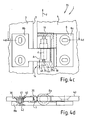
- FIGS. 4a to 4d show individual representations of a fourth partition wall 35, wherein the fourth partition 35 with respect to its basic structure with the in the FIGS. 2a and 2b shown second partition is comparable, since even with the partition wall 35, a door member 4 has a recess 14 which is arranged on a longitudinal edge 16 of the door member 4.
- the Indian FIG. 4a shown section of the partition 17 is part of a shower partition 2, which. also otherwise comparable to that in the FIGS. 2a and 2b shown second partition wall is formed and in which the door element 4 is also secured by means of two hinge straps on a wall element 3, wherein in the FIG. 3a only the wall element 3 and the door element 4 are shown.
- the wall element 3 and the door element 4 each have two conical bores 36 - 29 for attachment of the upper hinge band 8 (see Figure 4c ) on.
- FIG. 4b is a section through the depiction of FIG. 4a shown along the section line 4b-4b.
- the conical Holes 37 and 39 and the recess 14 can be seen.
- the wall element 3 and the door element 4 are formed of glass plates made of safety glass.
- FIG. 4d is a section through the depiction of Figure 4c shown along the section line 4d-4d. In this section is opposite to the Figure 4c In addition, a door seal 20 is shown, which is placed on the door element 3 and along a longitudinal edge 7 (see also Figure 4c ) of the door element 3 extends.
- the attachment of the hinge 8b in the conical bore 36 and in the other conical holes by means of a conical disc 40 with a threaded bore 41 and a countersunk screw 42. This results in an inner side 43 of the partition wall 35 a flush mounting of the hinge 8.
- first sealing element 18 is similar in terms of its shape to that in the FIGS. 3a to 3i executed shown first sealing element.
- the first sealing element 18 is connected by a fastening means 34 with the wing 8b of the hinge 8 rotatably about a rotational axis d of the hinge 8.
- closed position I of the partition wall 35 has a groove bottom 25a of the first sealing element 18 at a distance A to a peripheral edge 44 of the recess 14.
- a gap 45 which lies between the groove bottom 25a of the first sealing element 18 and the peripheral edge 44 of the recess 14 on the door element 4 is reduced. That is, the door member 4 pushes into the first stationary in the axial direction sealing element 19, wherein the first sealing member 19 rotates together with the door member 4 and the wing 8a of the hinge 8 about the axis of rotation 8.
- first sealing element form an elastically deformable seal, which can be stretched and squeezed.
Landscapes
- Health & Medical Sciences (AREA)
- Public Health (AREA)
- Epidemiology (AREA)
- General Health & Medical Sciences (AREA)
- Engineering & Computer Science (AREA)
- Mechanical Engineering (AREA)
- Hinges (AREA)
- Extensible Doors And Revolving Doors (AREA)
- Specific Sealing Or Ventilating Devices For Doors And Windows (AREA)
Abstract
Description
- Die Erfindung betrifft eine Trennwand, insbesondere Duschtrennwand, umfassend ein Wandelement und ein Türelement und wenigstens ein Gelenkband gemäß dem Oberbegriff des Anspruchs 1 und ein Gelenkband gemäß dem Oberbegriff des Anspruchs 15.
- Aus der
DE 203 04 389 U1 ist eine Trennwand bekannt, welche ein Wandelement, ein Türelement und wenigstens ein Gelenkband umfasst, wobei das Türelement insbesondere mittels zwei Gelenkbändern drehbar an dem Wandelement gelagert ist, wobei jedes Gelenkband einen ersten und einen zweiten Flügel aufweist, wobei sich das Wandelement und das Türelement mit Längskanten gegenüberliegen, wobei jedem Gelenkband eine Ausnehmung zugeordnet ist, welche an der Längskante des Wandelements oder des Türelements ausgebildet ist, wobei der erste Flügel und der zweite Flügel des Gelenkbands in die Ausnehmung eingreifen und wobei die beiden Flügel drehbar um eine Drehachse miteinander verbunden sind. Nachteilig an derartigen Trennwänden ist, dass insbesondere wenn die Trennwand eine am Türelement angeordnete zu einem Boden gerichteten und/oder eine am Boden angeordnete Dichtung aufweist, das Schließen und Öffnen erschwert ist und sich die Lebensdauer der Dichtung bzw. der Dichtungen durch starken Verschleiß verringert. - Der Erfindung liegt die Aufgabe zugrunde, eine Trennwand zu entwickeln, welche trotz einer Anordnung des Gelenkbands in einer Ausnehmung des Wandelements oder des Türelements ein widerstandsarmes Öffnen und Schließen des Türelements erlaubt und insbesondere bei geschlossenem Türelement eine Spritzwasserdichtigkeit im Bereich der Ausnehmung gewährleistet. Weiterhin ist es Aufgabe der Erfindung, ein Gelenkband zu entwickeln, welches auf sich verändernde Platzverhältnisse im Bereich seiner Drehachse anpassbar ist.
- Diese Aufgabe wird ausgehend von den Merkmalen des Oberbegriffs des Anspruchs 1 bzw. des Anspruchs 15 durch die kennzeichnenden Merkmale des Anspruchs 1 bzw. des Anspruchs 15 gelöst. In den Unteransprüchen sind vorteilhafte und zweckmäßige Weiterbildungen angegeben.
- Bei der erfindungsgemäßen Trennwand mit einem Wandelement, einem Türelements und wenigstens einem Gelenkband ist eine Drehbewegung des Türelements gegenüber dem Wandelement durch eine Axialbewegung des Türelements in Richtung der Drehachse überlagert, wobei die Axialbewegung durch die zusammenwirkenden Flügel des Gelenkbands erzeugbar ist und wobei eine Ausnehmung in ihren Abmessungen derart bemessen ist, dass der an dem Türelement angeordnete Flügel des Gelenkbands in der Ausnehmung zwischen einer abgesenkten Stellung und einer angehobenen Stellung in Richtung der Drehachse verfahrbar ist. Durch eine angepasste Dimensionierung der Ausnehmung ist es möglich ein Gelenkband mit einer Hebe-Senk-Funktion zu nutzen, durch welches das Türelement bei Öffnen angehoben und bei Schließen abgesenkt wird. Hierdurch kann eine ungewünschte Reibung im Bereich einer Unterkante an der Unterkante des Türelements vermieden werden.
- Weiterhin sieht die Erfindung vor, in einem Freiraum, welcher in der Ausnehmung zwischen dem Gelenkband und dem Wandelement bzw. dem Türelement gebildet ist, wenigstens ein Dichtelement anzuordnen. Hierdurch ist trotz vergrößerter Ausnehmung eine spritzwasserdichte Trennwand realisierbar, welche alle Anforderungen erfüllt, die an eine Duschtrennwand gestellt werden.
- Die Erfindung sieht eine Relativbeweglichkeit und/oder eine Verformbarkeit des ersten Dichtelements gegenüber wenigstens einer Randkante des Ausschnitts vor. Hierdurch ist eine Behinderung der Hebe-Senk- und Drehbewegung des Türelements durch das erste Dichtelement vermieden, da dieses in seiner Position und/oder in seiner Form an die in der jeweiligen Drehstellung des Türelements bestehenden Erfordernisse anpassbar ist.
- Erfindungsgemäß ist das erste Dichtelement an einem der Flügel des Gelenkbandes befestigt ist, wobei das erste Dichtelement insbesondere verdrehbar an diesem Flügel des Gelenkbands befestigt ist und wobei das erste Dichtelement insbesondere verdrehbar um die Drehachse des Gelenkbands an diesem Flügel des Gelenkbands befestigt ist. Hierdurch ist sichergestellt, dass das erste Dichtelement in der geschlossenen Stellung des Türelements immer seine Abdichtposition in der Ausnehmung einnimmt und nicht ungewollt, beispielsweise auf Grund erhöhter Reibung, in einer Offenposition stehen bleibt.
- Eine Ausführungsvariante der Erfindung sieht vor, das Wandelement mit der Ausnehmung zu versehen und das erste Dichtelement an dem bewegbaren Flügel des Gelenkbands zu befestigen, welcher dem Türelement zugeordnet ist, wobei das Dichtelement mit dem bewegbaren Flügel gegenüber dem Wandelement bei Drehung des Türelements um die Drehachse in axialer Richtung relativ zu dem Wandelement verfahrbar und/oder von dem bewegbaren Flügel des Gelenkbandes verformbar ist. Durch eine Verschiebung und/oder Kompression bzw. Dehnung des ersten Dichtelements zwischen dem Wandelement und dem dem Türelement zugeordneten Flügel des Gelenkbandes wird der Raum bereit gestellt, welcher für den sich beim Öffnen anhebenden Flügel des Scharnierbands erforderlich ist.
- Eine weitere Ausführungsvariante sieht vor, die Ausnehmung in dem Türelement anzuordnen und das erste Dichtelement an dem stillstehenden Flügel des Gelenkbands zu befestigen, welcher dem Wandelement zugeordnet ist, wobei das Türelement bei Drehung um die Drehachse relativ zu dem Dichtelement in axiale Richtung verfahrbar ist und/oder von dem Türelement verformbar ist. Hierdurch ist es dem Türelement möglich sich durch ein Gleiten in dem ersten Dichtelement und/oder ein Komprimieren bzw. Dehnen des ersten Dichtelements beim Öffnen des Türelements mit dem Flügel, welcher dem Türelement zugeordnet ist, nach oben in Richtung der Drehachse gegenüber dem Flügel, welcher dem Randelement zugeordnet ist, anzuheben.
- Weiterhin sieht die Erfindung vor, das erste Dichtelement durch ein L-förmiges Bauteil als Profil auszubilden, welches insbesondere wenigstens an einem Schenkel einen U-förmigen Querschnitt aufweist und mit seinen Stegen als Reiter eine Randkante der Ausnehmung übergreifen. Ein derartiges Dichtelement ist einfach herstellbar und lässt sich ohne weitere Bauteile sicher auf dem Wandelement bzw. dem Türelement führen.
- Gemäß der Erfindung ist es auch vorgesehen, in der Ausnehmung ein zweites Dichtelement anzuordnen, welches insbesondere als L-förmiges Profil ausgebildet ist und insbesondere wenigstens an einem Schenkel einen U-förmigen Querschnitt aufweist und mit diesem als Reiter wenigstens eine Randkante der Ausnehmung mit zwei Stegen übergreift. Ein derartiges zweites Dichtungselement ist einfach ohne Verklebung montierbar, da es in der Ausnehmung zwischen einem der Flügel und dem Wandelement bzw. dem Türelement gehalten wird.
- Schließlich sieht die Erfindung vor, den axial stillstehenden Flügel des Gelenkbands und/oder den axial verfahrbaren Flügel des Gelenkbands mittels konischer Scheiben mit Innengewinde oder Gewindestift flächenbündig an Senkbohrungen des Wandelements oder des Türelements zu verschrauben. Bei einer derartigen Befestigung des Gelenkbands lässt sich die Duschtrennwand an einer Innenseite einfach reinigen, da diese keine hervorstehenden Bauteile aufweist.
- Die Erfindung sieht auch ein Gelenkband vor, welches als Hebe-Senk-Gelenkband ausgebildet ist und an einem seiner Flügel ein erstes Dichtelement aufweist, welches mit diesem Flügel verbunden ist. Hierdurch ist es möglich mittels des Gelenkbands die Bewegung eines Dichtelements zu Steuern und so das Dichtelement abhängig von einer Drehstellung des Gelenkbands zu positionieren.
- Im Sinne der Erfindung wird unter einem Wandelement ein Element verstanden, welches insbesondere durch eine fest in einem Raum montierte Platte gebildet ist, wobei diese Platte insbesondere als Glasplatte ausgeführt ist. Im Sinne der Erfindung kann das Wandelement aber auch als feststehende Wand oder Mauer ausgebildet sein.
- Im Sinne der Erfindung wird unter einem Gelenkband ein Gelenk bzw. ein Scharnier verstanden, durch welches zwei Bauteile drehbar miteinander verbindbar sind.
- Weitere Einzelheiten der Erfindung werden in der Zeichnung anhand von schematisch dargestellten Ausführungsbeispielen beschrieben.
- Hierbei zeigt:
- Figur 1a - 1b:
- vereinfachte Seitenansichten auf eine ersten Trennwand, bei welcher das Wandelement zwei Ausschnitte aufweist;
- Figur 2a - 2b:
- vereinfachte Seitenansichten auf eine zweiten Trennwand, bei welcher das Türelement zwei Ausschnitte aufweist;
- Figur 3a:
- Detailansicht einer dritten Trennwand, bei welcher das Wandelement einen Ausschnitt aufweist;
- Figur 3b - 3i
- weitere Ansichten zu der in der
Figur 3a gezeigten Trennwand und - Figur 4a - 4d:
- Detailansicht einer vierten Trennwand, bei welcher das Türelement einen Ausschnitt aufweist.
- Die
Figuren 1a und 1b zeigen vereinfachte Seitenansichten einer ersten Trennwand 1. Die Trennwand 1 ist als Duschtrennwand 2 ausgeführt und umfasst ein feststehendes Wandelement 3 und ein gegenüber dem Wandelement 3 um eine Drehachse d drehbares Türelement 4. Das Wandelement 3 weist zwei Ausnehmungen 5, 6 auf, welche an einer senkrecht im Raum stehenden Längskante 7 des Wandelements 3 ausgebildet sind. Das Wandelement 3 und das Türelement 4 sind über Gelenkbänder 8, 9 miteinander verbunden. Die Gelenkbänder 8, 9 bestehen jeweils aus einem ersten Flügel 8a bzw. 9a, welcher mit dem Türelement 4 verbunden ist und einem zweiten Flügel 8b bzw. 9b, welcher mit dem Wandelement 3 verbunden ist. Die Flügel 8a, 8b bzw. 9a, 9b sind in der Ausnehmung 5 bzw. in der Ausnehmung 6 um die bereits erwähnte Drehachse d drehbar miteinander verbunden. Das Gelenkband 8 und das Gelenkband 9 sind in bekannter Weise als so genannte Hebe-Senk-Gelenke 10 ausgeführt, bei welchen sich ein in Richtung der Drehachse d gemessener Abstand zwischen den Flügeln 8a und 8b bzw. 9a und 9b durch ein Verdrehen des ersten Flügels 8a bzw. 9a gegenüber dem zweiten Flügel 8b bzw. 9b von einem Abstand a (sieheFigur 1a ) auf einen Abstand A (sieheFigur 1b ) durch das Zusammenwirken von nicht dargestellten Formteilen verändert. Somit ist eine Drehbewegung des Türelements 4 beim Öffnen des Türelements 4 aus der in derFigur 1a dargestellten abgesenkten Stellung I in die in derFigur 1b dargestellte angehobene Stellung II durch eine Axialbewegung in eine Pfeilrichtung y entlang der Drehachse d überlagert. Beim Schließen des Türelements 4 aus der in derFigur 1b gezeigten angehobenen Stellung II erfolgt dann eine Absenkbewegung in eine Pfeilrichtung y' entlang der Drehachse d. Um diese Hebe-Senk-Bewegung der Flügel 8a bzw. 9a der Gelenkbänder 8 bzw. 9 zu ermöglichen, weisen die Ausnehmungen 5 und 6 jeweils einen Freiraum 11 bzw. 12 auf, welcher erfindungsgemäß in der abgesenkten Stellung I durch jeweils wenigstens ein Dichtelement verschlossen ist, wobei die Dichtelemente in denFiguren 1a und 1b zur Erhaltung der Übersichtlichkeit nicht dargestellt sind. An einer Unterkante K4 des Türelements 4 ist eine Dichtung D angeordnet. Dies Dichtung wird mit dem Türelement 4 beim Öffnen angehoben und bremst somit das Öffnen des Türelements 4 nicht. Ebenso wir die Dichtung D beim Schließen des Türelements 4 wieder in derFigur 1a gezeigte Stellung angesenkt. - In den
Figuren 2a und 2b ist in vereinfachter Darstellung eine zweite Trennwand 13 dargestellt. Die zweite Trennwand 13 ist ebenfalls als Duschtrennwand 2 ausgeführt und umfasst ein Wandelement 3 und ein Türelement 4, welche über Gelenkbänder 8 und 9 verbunden sind, wobei im Unterschied zu der in denFiguren 1a und 1b gezeigten ersten Trennwand Ausnehmungen 14 und 15 nicht an dem Wandelement 3, sondern an einer Längskante 16 des Türelements 4 angeordnet sind. Die Gelenkbänder 8 und 9 umfassen jeweils zwei Flügel 8a, 8b bzw. 9a, 9b, welche um eine Drehachse d in der Ausnehmung 14 bzw. der Ausnehmung 15 drehbar miteinander verbunden sind. Die Gelenkbänder 8 und 9 sind wiederum als so genannte Hebe-Senk-Gelenke 10 ausgeführt. In einer in derFigur 2a gezeigten abgesenkten Stellung I des Flügelelements 4 weisen die Ausnehmungen 14, 15 jeweils unterhalb der Gelenkbänder 8 bzw. 9 Freiräume 11 bzw. 12 auf. Beim Öffnen des Türelements 4 aus der in derFigur 2a gezeigten abgesenkten Stellung I in eine in derFigur 2b gezeigte angehobene Stellung II wird das Türelement 4 von den Flügeln 8a und 9a in eine Pfeilrichtung y in Richtung der Drehachse d angehoben und tritt hierbei in die Freiräume 11 bzw. 12 ein. Erfindungsgemäß sind die Freiräume 11, 12 durch jeweils wenigstens ein Dichtelement verschlossen, wobei hier zur Erhaltung der Übersichtlichkeit auf die Darstellung von Dichtelementen verzichtet wurde. - In der
Figur 3a ist eine Detailansicht einer dritten Trennwand 17 dargestellt, wobei die dritte Trennwand 17 bezüglich ihres grundsätzlichen Aufbaus mit der in denFiguren 1a und 1b gezeigten ersten Trennwand vergleichbar ist, da auch bei der Trennwand 17 ein Wandelement 3 eine Ausnehmung 5 aufweist, welche an einer Längskante 7 des Wandelements 3 angeordnet ist. Der in derFigur 3a gezeigte Ausschnitt der Trennwand 17 gehört zu einer Duschtrennwand 2, welche auch ansonsten vergleichbar zu der in denFiguren 1a und 1b gezeigten ersten Trennwand ausgebildet ist und bei welcher ein Türelement 4 ebenfalls mittels zweier Gelenkbänder an dem Wandelement 3 befestigt ist, wobei in derFigur 3a nur das obere Gelenkband 8 gezeigt ist. Das Gelenkband 8 umfasst einen ersten Flügel 8a, welcher an dem Türelement 4 befestigt ist, und einen zweiten Flügel 8b, welcher an dem Wandelement 3 befestigt ist. Die Flügel 8a und 8b des Gelenkbands 8 sind in der Ausnehmung 5 miteinander verbunden und weisen miteinander eine Drehachse d auf, welche parallel zu der Längskante 7 des Wandelements 3 verläuft. Das Gelenkband 8 ist als so genanntes Hebe-Senk-Gelenk 10 ausgeführt. Die dritte Trennwand 17 umfasst neben dem Wandelement 3, dem Türelement 4 und dem Gelenkband 8 ein erstes Dichtelement 18, ein zweites Dichtelement 19 und eine herkömmliche Türdichtung 20, welche an dem Türelement 4 befestigt ist. In derFigur 3a steht das Gelenkband I bzw. das Türelement 4 in einer abgesenkten Stellung I, in welcher das Türelement 4 geschlossen ist. In dieser abgesenkten Stellung I ist die Ausnehmung 5 in dem Wandelement 3 durch die Flügel 8a und 8b und die beiden Dichtelemente 18 und 19 verschlossen bzw. gegen Spritzwasser abgedichtet. Mit gestrichelten Linien sind Randkanten 21, 22 und 23 angedeutet, welche die Ausnehmung 5 begrenzen. - In der
Figur 3b sind als Einzelteile aus derFigur 3a das Wandelement 3 mit seiner Ausnehmung 5, das erste Dichtelement 18 und das zweite Dichtelement 19 gezeigt. Die Ausnehmung 5 wird durch die bereits erwähnten Randkanten 21 bis 23 begrenzt. Das Wandelement 3 ist vorzugsweise aus Sicherheitsglas ausgeführt. Das erste Dichtelement 18 ist durch ein L-förmiges Profil 24 gebildet, welches zwei Schenkel 25, 26 aufweist. Die beiden Schenkel 25, 26 weisen jeweils einen U-förmigen Querschnitt auf (siehe auchFigur 3g ). Mit gestrichelten Linien Nutböden 25a und 25b angedeutet, welche durch diesen U-förmigen Querschnitt entstehen. Das erste Dichtelement 18 bildet einen Reiter 27, welcher auf das Wandelement 3 im Bereich des Ausschnitts 5 aufsetzbar ist. Das zweite Dichtelement 19 ist ebenfalls als L-förmiges Profil 28 ausgebildet, welches zwei Schenkel 29 und 30 aufweist. Diese beiden Schenkel 29, 30 haben jeweils einen U-förmigen Querschnitt. Durch den Querschnitt entstehenden Nutböden 29a und 30a sind mit gestrichelten Linien angedeutet (siehe auchFigur 3g ). Auch das zweite Dichtelement 19 bildet einen Reiter 31, welcher auf das Wandelement 3 im Bereich der Ausnehmung 5 aufschiebbar ist. Ein Aufschieben erfolgt in eine Pfeilrichtung p, wobei sich nach dem Aufschieben der Nutboden 29a und die Randkante 22 sowie der Nutboden 30a und die Randkante 23 gegenüber liegen. - In der
Figur 3c ist als weiteres Detail aus derFigur 3a das Gelenkband 8 dargestellt. Mit gestrichelten Linien sind eine dem Flügel 8a zugeordnete Hülse 32 und eine dem Flügel 8b zugeordnete Hülse 33 dargestellt, welche bei einer Drehbewegung um die Drehachse d ein Anheben in eine Pfeilrichtung y und danach ein Absenken in eine Pfeilrichtung y' des Flügels 8a gegenüber dem Flügel 8b bewirken. In den Hülsen 32, 33 verläuft in Richtung der Drehachse d ein nicht dargestellter Stift, welcher mit dem Flügel 8b verbunden ist und auf welchen der Flügel 8a in die Pfeilrichtung y' aufgesteckt ist. - In der
Figur 3d ist nochmals das Gelenkband 8 dargestellt. Im Unterschied zu derFigur 3c zeigt dieFigur 3d auch das erste Dichtelement 18, welches mit einem Befestigungsmittel 34 an dem Flügel 8a des Gelenkbands 8 befestigt ist. Das Befestigungsmittel 34 ermöglicht eine Relativbewegung zwischen dem Flügel 8a und dem ersten Dichtelement 18, um die Drehachse d. - In der
Figur 3e ist das Wandelement 3 mit dem bereits aufgeschobenen zweiten Dichtelement 19 dargestellt. Zusätzlich zeigt dieFigur 3e das Gelenkband 8 mit dem an dem Gelenkband 8 montierten ersten Dichtelement 18, wobei das aus derFigur 3d bekannte Befestigungselement zur Erhaltung der Übersichtlichkeit nicht dargestellt ist. Das Gelenkband 8 bildet zusammen mit dem ersten Dichtelement 18 eine Baugruppe, welche dafür vorgesehen ist, in eine Pfeilrichtung x' in die Ausnehmung 5 des Wandelements 3 eingeschoben zu werden. - Die
Figur 3f zeigt eine Ansicht des Wandelements 3, bei welcher die zuFigur 3e erwähnte Baugruppe bereits montiert ist. Selbstverständlich ist der Flügel 8b an dem Wandelement 3 befestigt, zur Erhaltung der Übersichtlichkeit ist diese Befestigung zeichnerisch nicht dargestellt. - In der
Figur 3g ist schließlich ein Schnitt durch die Darstellung derFigur 3f entlang der Schnittlinie 3g-3g gezeigt. In der Schnittansicht ist erkennbar, wie das erste Dichtelement 18 mit seinem Nutboden 25a der Randkante 21 der Ausnehmung 5 mit einem Abstand B gegenüber liegt und die wie Stege 25b und 25c des Schenkels 25 des ersten Dichtelements 18 das Türelement 3 seitlich umgreifen. Weiterhin ist erkennbar, wie das zweite Dichtelement 19 mit seinem Nutboden 30a auf der Randkante 23 der Ausnehmung 5 aufliegt und mit Stegen 30b und 30c das Türelement 3 im Bereich der Randkante 23 seitlich übergreift. Auch die Randkante 22 der Ausnehmung 5 wird von nicht näher bezeichneten Stegen der Dichtelemente 18 und 19 umgriffen (sieheFigur 3f ), wobei die Dichtelemente 18 und 19 mit ihren Nutböden 26a und 29a der Randkante 22 der Ausnehmung gegenüber liegen bzw. an dieser anliegen. - Im Vergleich zur
Figur 3f zeigt dieFigur 3h die Trennwand 17 nun in einer angehobenen Stellung II des Flügels 8a, in welcher der Flügel 8a zusammen mit dem lediglich in derFigur 3a dargestellten Türelement um 90° um die Drehachse d in die Zeichnungsebene hinein verschwenkt ist. Durch ein gegeneinander Verdrehen der Hülsen 32 und 33 vergrößert sich ein Abstand zwischen den Flügeln 8a und 8b auf von einem Abstand a in der abgesenkten Stellung I (sieheFigur 3f und 3g ) auf einen Abstand A in der angehobenen Stellung II (sieheFigur 3h und 3i ). Bei dieser Hebebewegung in eine Pfeilrichtung y wird das erste Dichtelement 18 von dem Flügel 8a des Gelenkbands 8 in die Pfeilrichtung y verschoben und nähert sich hierbei mit seinem Nutboden 25a der Randkante 21 der Ausnehmung 5 um eine Strecke A - a an. - In der
Figur 3i ist eine Seitenansicht auf die Darstellung derFigur 3h aus der Pfeilrichtung 3i gezeigt. In dieser Darstellung ist insbesondere im Vergleich zu derFigur 3g zu erkennen, wie sich das erste Dichtelement 18 auf das Wandelement 3 in y-Richtung aufschiebt, und hierdurch eine Hebe-Bewegung des mit dem Türelement 4 (sieheFigur 3a ) verbundenen Flügels 8a ermöglicht. Beim Zurückschwenken des Türelements 4 aus der angehobenen Stellung II in die abgesenkte, geschlossene Stellung I wird das erste Dichtelement 18 von dem Flügel 8a des Gelenkbands 8 in eine Pfeilrichtung y' nach unten gezogen, da es über das Befestigungsmittel 34 (sieheFigur 3d ) mit diesem verbunden ist. Hierdurch wird die Ausnehmung 5 in der abgesenkten Stellung I wieder sicher verschlossen, da das erste Dichtelement 18 über den Flügel 8 zwangsgesteuert ist. Das zweite Dichtelement 19 steht in den Stellungen I und II immer in der selben Position. - Die
Figuren 4a bis 4d zeigen einzelne Darstellungen einer vierten Trennwand 35, wobei die vierte Trennwand 35 bezüglich ihres grundsätzlichen Aufbaus mit der in denFiguren 2a und 2b gezeigten zweiten Trennwand vergleichbar ist, da auch bei der Trennwand 35 ein Türelement 4 eine Ausnehmung 14 aufweist, welche an einer Längskante 16 des Türelements 4 angeordnet ist. Der in derFigur 4a gezeigte Ausschnitt der Trennwand 17 gehört zu einer Duschtrennwand 2, welche.auch ansonsten vergleichbar zu der in denFiguren 2a und 2b gezeigten zweiten Trennwand ausgebildet ist und bei welcher das Türelement 4 ebenfalls mittels zweier Gelenkbänder an einem Wandelement 3 befestigt ist, wobei in derFigur 3a nur das Wandelement 3 und das Türelement 4 gezeigt sind. Das Wandelement 3 und das Türelement 4 weisen jeweils zwei konische Bohrungen 36 - 29 zur Befestigung des oberen Gelenkbands 8 (sieheFigur 4c ) auf. In derFigur 4b ist ein Schnitt durch die Darstellung derFigur 4a entlang der Schnittlinie 4b-4b dargestellt. Im Schnitt sind die konischen Bohrungen 37 und 39 und die Ausnehmung 14 erkennbar. Weiterhin ist erkennbar, dass das Wandelement 3 und das Türelement 4 aus Glasplatten aus Sicherheitsglas ausgebildet sind. - In der
Figur 4c ist der aus derFigur 4a bekannte Ausschnitt nochmals dargestellt, wobei nun das Gelenkband 8 mit seinen Flügeln 8a und 8b und das erste Dichtelement 18 und das zweite Dichtelement 19 in die Ausnehmung 14 des Türelements 4 eingesetzt sind. - In der
Figur 4d ist ein Schnitt durch die Darstellung derFigur 4c entlang der Schnittlinie 4d-4d gezeigt. In diesem Schnitt ist gegenüber derFigur 4c zusätzlich eine Türdichtung 20 gezeigt, welche auf das Türelement 3 aufgesetzt ist und entlang einer Längskante 7 (siehe auchFigur 4c ) des Türelements 3 verläuft. Die Befestigung des Gelenkbands 8b in der konischen Bohrung 36 sowie in den anderen konischen Bohrungen erfolgt mittels einer konischen Scheibe 40 mit einer Gewindebohrung 41 und einer Senkkopfschraube 42. Hierdurch ergibt sich zu einer Innenseite 43 der Trennwand 35 eine flächenbündige Befestigung des Gelenkbands 8. - Das in der
Figur 4c gezeigte erste Dichtelement 18 ist bezüglich seiner Formgebung vergleichbar zu dem in denFiguren 3a bis 3i gezeigten ersten Dichtelement ausgeführt. Das erste Dichtelement 18 ist durch ein Befestigungsmittel 34 mit dem Flügel 8b des Gelenkbands 8 drehbar um eine Drehachse d des Gelenkbands 8 verbunden. In einer in derFigur 4c gezeigten geschlossenen Stellung I der Trennwand 35 weist ein Nutboden 25a des ersten Dichtelements 18 einen Abstand A zu einer Randkante 44 der Ausnehmung 14 auf. Sobald das Türelement 4 zusammen mit dem Flügel 8a des Gelenkbands 8 in eine nicht dargestellte angehobene Stellung gedreht wird, hebt sich das Türelement 4 zusammen mit dem Flügel 8a auch in eine Pfeilrichtung y an. Hierbei wird verkleinert sich ein Spalt 45, welcher zwischen dem Nutboden 25a des ersten Dichtelements 18 und der Randkante 44 der Ausnehmung 14 an dem Türelement 4 liegt. Das heißt, das Türelement 4 schiebt sich in das in axialer Richtung stillstehende erste Dichtelement 19 hinein, wobei sich das erste Dichtelement 19 zusammen mit dem Türelement 4 und dem Flügel 8a des Gelenkbands 8 um die Drehachse 8 dreht. - Die Erfindung ist nicht auf dargestellte oder beschriebene Ausführungsbeispiele beschränkt. Sie umfasst vielmehr Weiterbildungen der Erfindung im Rahmen der Schutzrechtsansprüche. Insbesondere sieht die Erfindung auch vor, dass erste Dichtungselement als elastisch verformbare Dichtung auszubilden, welche gedehnt und gequetscht werden kann.
-
- 1
- Trennwand
- 2
- Duschtrennwand
- 3
- Wandelement
- 4
- Türelement
- 5
- Ausnehmung in 3
- 6
- Ausnehmung in 3
- 7
- Längskante von 3
- 8
- Gelenkband
- 8a
- erster Flügel von 8
- 8b
- zweiter Flügel von 8
- 9
- Gelenkband
- 9a
- erster Flügel von 9
- 9b
- weiter Flügel von 9
- 10
- Hebe-Senk-Gelenk
- 11
- Freiraum
- 12
- Freiraum
- 13
- zweite Trennwand
- 14
- Ausnehmung in 4
- 15
- Ausnehmung in 4
- 16
- Längskante von 4
- 17
- dritte Trennwand
- 18
- erstes Dichtelement
- 19
- zweites Dichtelement
- 20
- Türdichtung
- 21
- Randkante von 5
- 22
- Randkante von 5
- 23
- Randkante von 5
- 24
- L-förmiges Profil
- 25
- Schenkel von 24
- 25a
- Nutboden an 25
- 25b
- Steg an 25
- 25c
- Steg an 225
- 26
- Schenkel an 24
- 26a
- Nutboden von 26
- 27
- Reiter
- 28
- L-förmiges Profil
- 29
- Schenkel von 28
- 29a
- Nutboden an 29
- 30
- Schenkel von 28
- 30a
- Nutboden an 30
- 30b
- Steg an 30
- 30c
- Steg an 30
- 31
- Reiter
- 32
- Hülse an 8a
- 33
- Hülse an 8b
- 34
- Befestigungsmittel für 18 and 8a
- 35
- vierte Trennwand
- 36 - 39
- konische Bohrung in 3 bzw. 4
- 40
- konische Scheibe
- 41
- Gewindebohrung in 40
- 42
- Senkkopfschraube
- 43
- Innenseite von 35
- 44
- Randkante von 14
- 45
- Spalt zwischen 44 und 25a in 14
- A
- Abstand zwischen 8a und 8b in II
- a
- Abstand zwischen 8a und 8b in I
- B
- Abstand zwischen 25 und 21 in I
- b
- Abstand zwischen 25a und 21 in II
- d
- Drehachse
- D
- Dichtung an K4
- K4
- Unterkante von 4
- p
- Pfeilrichtung
- x
- Raumrichtung
- x'
- Raumrichtung
- Y
- Raumrichtung
- y'
- Raumrichtung
Claims (16)
- Trennwand (1; 13; 17; 35), insbesondere Duschtrennwand (2), umfassend ein Wandelement (3) und ein Türelement (4) und wenigstens ein Gelenkband (8; 9),- wobei das Türelement (4) insbesondere mittels zwei Gelenkbändern (8; 9) drehbar an dem Wandelement (3) gelagert ist,- wobei jedes Gelenkband (8; 9) einen ersten und einen zweiten Flügel (8a, 8b; 9a, 9b) aufweist,- wobei sich das Wandelement (3) und das Türelement (4) mit Längskanten (7; 16) gegenüberliegen,- wobei jedem Gelenkband (8; 9) eine Ausnehmung (5, 6; 14, 15) zugeordnet ist, welche an der Längskante (7; 16) des Wandelements (3) oder des Türelements (4) ausgebildet ist,- wobei der erste Flügel (8a; 9a) und der zweite Flügel (8b; 9b) des Gelenkbands (8; 9) in die Ausnehmung (5, 6; 14, 15) eingreifen und- wobei die beiden Flügel (8a, 8b; 9a, 9b) drehbar um eine Drehachse (d) miteinander verbunden sind,dadurch gekennzeichnet, dass- eine Drehbewegung des Türelements (4) gegenüber dem Wandelement (3) durch eine Axialbewegung des Türelements (4) in Richtung der Drehachse (d) überlagert ist,- wobei die Axialbewegung durch die zusammenwirkenden Flügel (8a, 8b; 9a, 9b) des Gelenkbands (8; 9) erzeugbar ist und- wobei die Ausnehmung (5, 6; 14, 15) so bemessen ist, dass der an dem Türelement (4) angeordnete Flügel (8a; 9a) des Gelenkbands (8; 9) in der Ausnehmung (5, 6; 14, 15) zwischen einer abgesenkten Stellung (I) und einer angehobenen Stellung (II) in Richtung der Drehachse (d) verfahrbar ist.
- Trennwand nach Anspruch 1, dadurch gekennzeichnet, dass in der Ausnehmung (5, 6; 14, 15) zwischen dem Gelenkband (8; 9) und dem Wandelement (3) bzw. dem Türelement (4) wenigstens ein Dichtelement (18, 19) angeordnet ist.
- Trennwand nach einem der vorhergehenden Ansprüche, dadurch gekennzeichnet, dass das erste Dichtelement (18) gegenüber wenigstens einer Randkante (21, 22, 23; 44) des Ausschnitts (5, 6; 14, 15) relativbeweglich und/oder verformbar ist.
- Trennwand nach einem der vorhergehenden Ansprüche, dadurch gekennzeichnet, dass das erste Dichtelement (18) an einem der Flügel (8a, 8b; 9a, 9b) des Gelenkbands (8; 9) befestigt ist, wobei das erste Dichtelement (18) insbesondere verdrehbar an diesem Flügel (8a, 8b; 9a, 9b) befestigt ist und wobei das erste Dichtelement (18) insbesondere verdrehbar um die Drehachse (d) des Gelenkbands (8; 9) an diesem Flügel (8a, 8b; 9a, 9b) befestigt ist.
- Trennwand nach einem der vorhergehenden Ansprüche, dadurch gekennzeichnet, dass die Ausnehmung (5, 6; 14, 15) in dem Wandelement (3) angeordnet ist und dass das erste Dichtelement (18) an dem dem Türelement (4) zugeordneten, bewegbaren Flügel (8a,; 9a) des Gelenkbands (8; 9) befestigt ist und mit dem bewegbaren Flügel (8a; 9a) gegenüber dem Wandelement (3) bei Drehung um die Drehachse (d) in axialer Richtung (y, y') relativ zu dem Wandelement (3) verfahrbar und/oder von dem bewegbaren Flügel (8a; 9a) des Gelenkbands (8; 9) verformbar ist.
- Trennwand nach einem der vorhergehenden Ansprüche 1 bis 4, dadurch gekennzeichnet, dass die Ausnehmung (5, 6; 14, 15) in dem Türelement (4) angeordnet ist und dass das erste Dichtelement (18) an dem dem Wandelement (3) zugeordneten, stillstehenden Flügel (8b; 9b) des Gelenkbands (8; 9) befestigt ist und dass das Türelement (4) bei Drehung um die Drehachse (d) relativ zu dem ersten Dichtelement (18) in axiale Richtung (y, y') verfahrbar ist und/oder von dem Türelement (4) verformbar ist.
- Trennwand nach einem der vorhergehenden Ansprüche, dadurch gekennzeichnet, dass das erste Dichtelement (18) durch ein L-förmiges Profil (24) gebildet ist, welches insbesondere wenigstens an einem Schenkel (25, 26) einen U-förmigen Querschnitt aufweist und mit diesem als Reiter (27) eine Randkante (21, 22, 23; 44) der Ausnehmung (5, 6; 14, 15) übergreift.
- Trennwand nach einem der vorhergehenden Ansprüche, dadurch gekennzeichnet, dass in der Ausnehmung (5, 6; 14, 15) ein zweites Dichtelement (19) angeordnet ist, welches insbesondere als L-förmiges Profil (28) ausgebildet ist und insbesondere wenigstens an einem Schenkel (29, 30) einen U-förmigen Querschnitt aufweist und mit diesem als Reiter (31) wenigstens eine Randkante (21, 22, 23; 44) der Ausnehmung (5, 6; 14, 15) übergreift.
- Trennwand nach Anspruch 8, dadurch gekennzeichnet, dass die Ausnehmung (5, 6) in dem Wandelement (3) angeordnet ist und das zweite Dichtelement (19) in dieser Ausnehmung (5, 6) zwischen dem Wandelement (3) und dem stillstehenden Flügel (8b; 9b) des Gelenkbands (8; 9) angeordnet ist.
- Trennwand nach Anspruch 8, dadurch gekennzeichnet, dass die Ausnehmung (14, 15) in dem Türelement (4) angeordnet ist und das zweite Dichtelement (19) in dieser Ausnehmung (14, 15) zwischen dem Türelement (4) und dem drehbaren Flügel (8a; 9a) des Gelenkbands (8; 9) angeordnet ist.
- Trennwand nach einem der vorhergehenden Ansprüche, dadurch gekennzeichnet, dass der axial stillstehende Flügel (8b; 9b) des Gelenkbands (8; 9) und/oder der axial verfahrbare Flügel (8a; 9a) des Gelenkbands (8; 9) mittels konischer Scheiben (40) mit Innengewinde (41) oder Gewindestift flächenbündig in Senkbohrungen (36 - 39) des Wandelements (3) oder des Türelements (4) verschraubbar ist.
- Trennwand nach einem der vorhergehenden Ansprüche, dadurch gekennzeichnet, dass ein Freiraum (11; 12) in der Ausnehmung (5, 6; 14, 15) zwischen dem Gelenkband (8; 9) und dem Türelement (4) oder dem Wandelement (3) durch das wenigstens eine Dichtelement (18, 19) in der abgesenkten bzw. geschlossenen Stellung (I) des Türelements (3) abdichtbar ist.
- Trennwand nach einem der vorhergehenden Ansprüche, dadurch gekennzeichnet, dass das Türelement (3) als Glasplatte, insbesondere aus Sicherheitsglas, ausgebildet ist.
- Trennwand nach einem der vorhergehenden Ansprüche, dadurch gekennzeichnet, dass das Wandelement (4) als Glasplatte, insbesondere aus Sicherheitsglas, ausgebildet ist.
- Gelenkband (8; 9) mit einem ersten Flügel (8a; 9a) und einem zweiten Flügel (8b; 9b), welche drehbar um eine Drehachse (d) miteinander verbunden sind, wobei das Gelenkband (8; 9) als Hebe-Senk-Gelenkband (10) ausgebildet ist, dadurch gekennzeichnet, dass an einem der Flügel (8a; 8b; 9a; 9b) ein erstes Dichtelement (18) befestigbar ist.
- Gelenkband nach Anspruch 15, dadurch gekennzeichnet, dass das erste Dichtelement (18) insbesondere verdrehbar an dem jeweiligen Flügel (8a, 8b; 9a, 9b) befestigbar ist und dass das erste Dichtelement (18) insbesondere verdrehbar um die Drehachse (d) des Gelenkbands (8; 9) an dem jeweiligen Flügel (8a, 8b; 9a, 9b) befestigbar ist.
Applications Claiming Priority (1)
| Application Number | Priority Date | Filing Date | Title |
|---|---|---|---|
| DE200810012274 DE102008012274A1 (de) | 2008-03-03 | 2008-03-03 | Trennwand mit Gelenkband und Gelenkband für eine Trennwand |
Publications (3)
| Publication Number | Publication Date |
|---|---|
| EP2098148A2 true EP2098148A2 (de) | 2009-09-09 |
| EP2098148A3 EP2098148A3 (de) | 2011-04-27 |
| EP2098148B1 EP2098148B1 (de) | 2018-09-26 |
Family
ID=40599972
Family Applications (1)
| Application Number | Title | Priority Date | Filing Date |
|---|---|---|---|
| EP09001734.4A Active EP2098148B1 (de) | 2008-03-03 | 2009-02-07 | Trennwand mit Gelenkband |
Country Status (2)
| Country | Link |
|---|---|
| EP (1) | EP2098148B1 (de) |
| DE (1) | DE102008012274A1 (de) |
Cited By (2)
| Publication number | Priority date | Publication date | Assignee | Title |
|---|---|---|---|---|
| GB2563907A (en) * | 2017-06-29 | 2019-01-02 | Kohler Mira Ltd | Shower door hinge assembly |
| GB2581381A (en) * | 2019-02-15 | 2020-08-19 | Sum Chow Chi | Hinge for glass doors |
Families Citing this family (2)
| Publication number | Priority date | Publication date | Assignee | Title |
|---|---|---|---|---|
| DE202009013693U1 (de) | 2009-11-09 | 2010-01-07 | Munch, Paul-Jean | Rahmenlose Duschabtrennung |
| DE102019105018B4 (de) * | 2019-02-27 | 2020-09-24 | Joh. Sprinz Gmbh & Co. Kg | Scharnier mit elastischem Rückhalteelement |
Citations (1)
| Publication number | Priority date | Publication date | Assignee | Title |
|---|---|---|---|---|
| DE20304389U1 (de) | 2003-03-18 | 2003-06-05 | Altura Leiden Holding B.V., Vianen | Trennwand |
Family Cites Families (3)
| Publication number | Priority date | Publication date | Assignee | Title |
|---|---|---|---|---|
| DE202004000351U1 (de) * | 2004-01-13 | 2004-04-08 | Beck, Roland | Duschtürbeschlag mit Abdichtsystem |
| DE202006012415U1 (de) * | 2006-08-11 | 2006-11-23 | Schulte Duschkabinenbau Gmbh & Co. Kg | Scharnier und Duschabtrennung sowie Wandhalterung |
| DE202007001139U1 (de) * | 2007-01-19 | 2008-02-28 | Altura Leiden Holding B.V. | Trennwand, insbesondere Duschtrennwand |
-
2008
- 2008-03-03 DE DE200810012274 patent/DE102008012274A1/de not_active Withdrawn
-
2009
- 2009-02-07 EP EP09001734.4A patent/EP2098148B1/de active Active
Patent Citations (1)
| Publication number | Priority date | Publication date | Assignee | Title |
|---|---|---|---|---|
| DE20304389U1 (de) | 2003-03-18 | 2003-06-05 | Altura Leiden Holding B.V., Vianen | Trennwand |
Cited By (5)
| Publication number | Priority date | Publication date | Assignee | Title |
|---|---|---|---|---|
| GB2563907A (en) * | 2017-06-29 | 2019-01-02 | Kohler Mira Ltd | Shower door hinge assembly |
| US11193316B2 (en) | 2017-06-29 | 2021-12-07 | Kohler Mira Limited | Shower door hinge assembly |
| GB2563907B (en) * | 2017-06-29 | 2022-06-08 | Kohler Mira Ltd | Shower door hinge assembly |
| GB2581381A (en) * | 2019-02-15 | 2020-08-19 | Sum Chow Chi | Hinge for glass doors |
| GB2581381B (en) * | 2019-02-15 | 2021-08-18 | Sum Chow Chi | Hinge |
Also Published As
| Publication number | Publication date |
|---|---|
| EP2098148A3 (de) | 2011-04-27 |
| DE102008012274A1 (de) | 2009-09-10 |
| EP2098148B1 (de) | 2018-09-26 |
Similar Documents
| Publication | Publication Date | Title |
|---|---|---|
| DE69225792T2 (de) | Mehrpunkt-türverriegelung mit nocken-ritzelementen | |
| AT502611B1 (de) | Scharnier | |
| EP2824270B1 (de) | Flächenelement einer Brandschutzverglasung, insbesondere Glastür für Brandschutzzwecke zur Vermeidung des Durchtritts von Feuer und Rauch im Brandfall von einem Raum in einen anderen | |
| EP1707717A2 (de) | Vorreiberverschluss mit Selbstmontage | |
| DE3010703A1 (de) | Tuerschliesseranordnung | |
| EP2682545B1 (de) | Verschlussanordnung für eine Schiebetür oder ein Schiebefenster, und Schiebetür oder Schiebefenster | |
| EP2245252B1 (de) | Einstellbares ecklager für einen flügel eines fensters, einer tür oder dergleichen | |
| EP2098148B1 (de) | Trennwand mit Gelenkband | |
| DE102008004429A1 (de) | Endabdeckung für ein Gehäuse mit Stelleinrichtung und Vorrichtung zur Gehäuseanordnung an einem Flügel | |
| EP2189091B1 (de) | Duschabtrennung | |
| EP1771635A1 (de) | Gelenkband für glastüren | |
| EP2374973B1 (de) | Band für Türen, Fenster oder dergleichen | |
| CH665873A5 (de) | Scharnier zum beweglichen verbinden zweier teile, insbesondere fuer kuehlschraenke. | |
| EP3871575A1 (de) | Scharnier | |
| EP1813754B1 (de) | Obertürschliesser | |
| DE202018002548U1 (de) | Beschlag und Duschabtrennung | |
| EP2722472B1 (de) | Drehflügelbeschlag und Duschabtrennung | |
| EP1876319B1 (de) | Gleitfuehrung fuer Schiebefluegel oder Abstellschiebefluegel | |
| EP2175096B1 (de) | Scharnier einer Verschlusseinrichtung, beispielsweise eines Fensters, einer Tür oder dergleichen, sowie Verschlusseinrichtung mit einem solchen Scharnier | |
| DE202009001411U1 (de) | Vorrichtung zum Verschliessen eines Durchgangs | |
| DE102008029320B3 (de) | Klemmbeschlag, Anschlagtür und Gargerät | |
| DE29808660U1 (de) | Tür- oder Fensterdrehband | |
| DE102017202727A1 (de) | Verdeckt angeordneter Beschlag für Fenster, Türen oder dergleichen | |
| DE102008036587A1 (de) | Sektionaltor mit Dichtelement als Klemmschutz | |
| DE102009006969A1 (de) | Vorrichtung zum Verschliessen eines Durchgangs |
Legal Events
| Date | Code | Title | Description |
|---|---|---|---|
| PUAI | Public reference made under article 153(3) epc to a published international application that has entered the european phase |
Free format text: ORIGINAL CODE: 0009012 |
|
| AK | Designated contracting states |
Kind code of ref document: A2 Designated state(s): AT BE BG CH CY CZ DE DK EE ES FI FR GB GR HR HU IE IS IT LI LT LU LV MC MK MT NL NO PL PT RO SE SI SK TR |
|
| AX | Request for extension of the european patent |
Extension state: AL BA RS |
|
| RIC1 | Information provided on ipc code assigned before grant |
Ipc: E05F 1/04 20060101ALI20101124BHEP Ipc: E05D 5/02 20060101ALI20101124BHEP Ipc: A47K 3/36 20060101AFI20090619BHEP Ipc: E05D 7/00 20060101ALI20101124BHEP |
|
| PUAL | Search report despatched |
Free format text: ORIGINAL CODE: 0009013 |
|
| AK | Designated contracting states |
Kind code of ref document: A3 Designated state(s): AT BE BG CH CY CZ DE DK EE ES FI FR GB GR HR HU IE IS IT LI LT LU LV MC MK MT NL NO PL PT RO SE SI SK TR |
|
| AX | Request for extension of the european patent |
Extension state: AL BA RS |
|
| 17P | Request for examination filed |
Effective date: 20111027 |
|
| AKX | Designation fees paid |
Designated state(s): AT CH DE LI |
|
| GRAP | Despatch of communication of intention to grant a patent |
Free format text: ORIGINAL CODE: EPIDOSNIGR1 |
|
| INTG | Intention to grant announced |
Effective date: 20180516 |
|
| GRAS | Grant fee paid |
Free format text: ORIGINAL CODE: EPIDOSNIGR3 |
|
| GRAA | (expected) grant |
Free format text: ORIGINAL CODE: 0009210 |
|
| AK | Designated contracting states |
Kind code of ref document: B1 Designated state(s): AT CH DE LI |
|
| REG | Reference to a national code |
Ref country code: CH Ref legal event code: EP |
|
| REG | Reference to a national code |
Ref country code: AT Ref legal event code: REF Ref document number: 1045023 Country of ref document: AT Kind code of ref document: T Effective date: 20181015 |
|
| REG | Reference to a national code |
Ref country code: DE Ref legal event code: R096 Ref document number: 502009015305 Country of ref document: DE |
|
| REG | Reference to a national code |
Ref country code: DE Ref legal event code: R097 Ref document number: 502009015305 Country of ref document: DE |
|
| PLBE | No opposition filed within time limit |
Free format text: ORIGINAL CODE: 0009261 |
|
| STAA | Information on the status of an ep patent application or granted ep patent |
Free format text: STATUS: NO OPPOSITION FILED WITHIN TIME LIMIT |
|
| 26N | No opposition filed |
Effective date: 20190627 |
|
| REG | Reference to a national code |
Ref country code: CH Ref legal event code: PL |
|
| PG25 | Lapsed in a contracting state [announced via postgrant information from national office to epo] |
Ref country code: CH Free format text: LAPSE BECAUSE OF NON-PAYMENT OF DUE FEES Effective date: 20190228 Ref country code: LI Free format text: LAPSE BECAUSE OF NON-PAYMENT OF DUE FEES Effective date: 20190228 |
|
| REG | Reference to a national code |
Ref country code: AT Ref legal event code: MM01 Ref document number: 1045023 Country of ref document: AT Kind code of ref document: T Effective date: 20190207 |
|
| PG25 | Lapsed in a contracting state [announced via postgrant information from national office to epo] |
Ref country code: AT Free format text: LAPSE BECAUSE OF NON-PAYMENT OF DUE FEES Effective date: 20190207 |
|
| PGFP | Annual fee paid to national office [announced via postgrant information from national office to epo] |
Ref country code: DE Payment date: 20240216 Year of fee payment: 16 |