EP2097589B1 - Sanitäres einbauelement - Google Patents
Sanitäres einbauelement Download PDFInfo
- Publication number
- EP2097589B1 EP2097589B1 EP07856279.0A EP07856279A EP2097589B1 EP 2097589 B1 EP2097589 B1 EP 2097589B1 EP 07856279 A EP07856279 A EP 07856279A EP 2097589 B1 EP2097589 B1 EP 2097589B1
- Authority
- EP
- European Patent Office
- Prior art keywords
- insert element
- element according
- valve body
- valve
- filter screen
- Prior art date
- Legal status (The legal status is an assumption and is not a legal conclusion. Google has not performed a legal analysis and makes no representation as to the accuracy of the status listed.)
- Active
Links
Images


Classifications
-
- E—FIXED CONSTRUCTIONS
- E03—WATER SUPPLY; SEWERAGE
- E03C—DOMESTIC PLUMBING INSTALLATIONS FOR FRESH WATER OR WASTE WATER; SINKS
- E03C1/00—Domestic plumbing installations for fresh water or waste water; Sinks
- E03C1/02—Plumbing installations for fresh water
- E03C1/08—Jet regulators or jet guides, e.g. anti-splash devices
- E03C1/084—Jet regulators with aerating means
-
- B—PERFORMING OPERATIONS; TRANSPORTING
- B05—SPRAYING OR ATOMISING IN GENERAL; APPLYING FLUENT MATERIALS TO SURFACES, IN GENERAL
- B05B—SPRAYING APPARATUS; ATOMISING APPARATUS; NOZZLES
- B05B1/00—Nozzles, spray heads or other outlets, with or without auxiliary devices such as valves, heating means
-
- E—FIXED CONSTRUCTIONS
- E03—WATER SUPPLY; SEWERAGE
- E03C—DOMESTIC PLUMBING INSTALLATIONS FOR FRESH WATER OR WASTE WATER; SINKS
- E03C1/00—Domestic plumbing installations for fresh water or waste water; Sinks
- E03C1/02—Plumbing installations for fresh water
- E03C1/08—Jet regulators or jet guides, e.g. anti-splash devices
- E03C1/086—Jet regulators or jet guides, easily mountable on the outlet of taps
-
- B—PERFORMING OPERATIONS; TRANSPORTING
- B01—PHYSICAL OR CHEMICAL PROCESSES OR APPARATUS IN GENERAL
- B01D—SEPARATION
- B01D35/00—Filtering devices having features not specifically covered by groups B01D24/00 - B01D33/00, or for applications not specifically covered by groups B01D24/00 - B01D33/00; Auxiliary devices for filtration; Filter housing constructions
- B01D35/02—Filters adapted for location in special places, e.g. pipe-lines, pumps, stop-cocks
-
- Y—GENERAL TAGGING OF NEW TECHNOLOGICAL DEVELOPMENTS; GENERAL TAGGING OF CROSS-SECTIONAL TECHNOLOGIES SPANNING OVER SEVERAL SECTIONS OF THE IPC; TECHNICAL SUBJECTS COVERED BY FORMER USPC CROSS-REFERENCE ART COLLECTIONS [XRACs] AND DIGESTS
- Y10—TECHNICAL SUBJECTS COVERED BY FORMER USPC
- Y10S—TECHNICAL SUBJECTS COVERED BY FORMER USPC CROSS-REFERENCE ART COLLECTIONS [XRACs] AND DIGESTS
- Y10S261/00—Gas and liquid contact apparatus
- Y10S261/22—Faucet aerators
Definitions
- the invention relates to a sanitary installation element with at least one by-pass channel, to which a valve is assigned, in the open position of which at least one by-pass channel is connected.
- Sanitary installation elements which are designed as a jet regulator which can be inserted into the outlet mouthpiece of a sanitary outlet fitting are already known.
- Such jet regulators which are provided to produce a homogeneous and pearly-soft water jet, have in the housing interior of their installation housing a jet splitter, which can be configured as a diffuser or as a perforated plate. While the perforated plate has a plurality of flow holes each producing a single jet, the diffuser has a baffle plate which is delimited by a wall section interrupted by passage openings.
- the known installation element is configured as a jet regulator insert, which can be switched between a powerful cleaning jet and a soft ventilated overall jet.
- the previously known jet regulator insert has for this purpose a central cleaning jet channel, which surrounds an annular flow chamber with a multiplicity of water outlet nozzles.
- the flow chamber provided for generating the soft ventilated overall jet has an inflow opening which can be controlled with a valve biased into its closed position in such a way that the inflowing water opens the valve by a predeterminable backpressure of the water.
- the cleaning jet can be advantageously used, for example, for cleaning a razor
- a soft jet composed of a plurality of individual jets is produced when the valve is opened as a result of the water pressure. Since the so-called soft jet includes the powerful cleaning jet, it always results even with a corresponding water pressure a comparatively uncomfortable perceived and centrally splashing overall jet.
- the cleaning jet of the prior art jet regulator is also provided only for external cleaning purposes, but not for self-cleaning of the jet regulator for the purpose of maintaining its intended functions.
- the installation element has a filter with at least one outlet opening, which outlet has a larger compared to the filter openings of the filter screen clear opening cross-section that the at least one outlet opening in the at least opens a by-pass channel, and that the outlet opening in the flow direction before and the channel outlet of the at least one by-pass channel downstream of at least one liquid-conducting component of at least one functional unit located in the installation element is arranged.
- the installation element according to the invention has a filter screen with at least one outlet opening, which intercepts the dirt particles entrained in the water and can accumulate in order to discharge them via its outlet opening.
- the outlet opening of this filter sieve has an enlarged opening cross-section which is larger in comparison to the filter openings of the filter sieve.
- the at least one outlet opening opens into the at least one by-pass channel, through which the accumulated dirt particles can be removed.
- the at least one outlet opening of the filter screen is arranged in the flow direction before and the channel outlet of the by-pass channel downstream of at least one liquid-conducting component of at least one functional unit located in the installation element.
- the installation element according to the invention is therefore characterized by a comfortable operation with constant flow velocities. Since the functioning of a water-bearing component potentially hazardous dirt particles can be dissipated via the by-pass channel during the interruption of water supply, a low-maintenance and trouble-free operation of the installation element according to the invention and the functional units therein is ensured simultaneously.
- the at least one valve is movable from its open position under the back pressure of the inflowing water in its closed position.
- a preferred and particularly advantageous embodiment according to the invention provides that the installation element is designed to be self-cleaning and that for this purpose the at least one valve under the back pressure of the inflowing water is movable against a restoring force in its closed position.
- the valve is basically held in its open position by the restoring force. Since the valve is movable from its open position under the back pressure of the incoming water against the restoring force in its closed position, the valve is held by the inflowing water in its closed position, only with the interruption of the flow of water under closing the outlet fitting open so that the accumulated dirt particles can be removed.
- the functioning of a water-bearing component hazardous dirt particles can be removed via the by-pass channel during the interruption of the water supply, which is done regularly when closing the water flow controlling outlet fitting.
- a preferred embodiment according to the invention provides that the installation element has a jet regulator as a functional unit and that a jet splitter is provided as at least one of the liquid-conducting components. Since just the jet splitter of a jet regulator with its comparatively small flow cross-sections is endangered by dirt particles entrained in the water, the built-in element according to the invention with its self-cleaning properties can be used advantageously in conjunction with a jet regulator.
- the jet splitter can be configured as a perforated plate or as a diffuser.
- the filter openings of the filter screen have an equal or smaller clear flow cross-section compared to the flow openings of the at least one liquid-conducting component. In this way, it is ensured that such dirt particles, which may have passed through the filter openings of the filter screen, can also pass through the flow openings of the jet breaker.
- the at least one functional unit is connected downstream of the filter openings of the filter in the flow direction.
- the purified by the filter openings of the filter water jet is always supplied to the at least one functional unit.
- a preferred embodiment according to the invention provides that at least one valve has a valve body, which is displaceably guided in the installation element against a restoring force.
- a particularly advantageous development according to the invention provides that a portion of the valve body passed through the installation element protrudes at least approximately as far as the water outlet of the installation element and is configured as a handle for manual actuation of the valve.
- the protruding over the water outlet of the installation member portion of the valve body can not only recognize the respective operating position of the valve, but the user can if necessary beyond the automatic self-cleaning of the installation element according to the invention also trigger further self-cleaning operations, if he the valve body at the designed as a handle portion Need moved into its open position.
- valve body is mushroom-shaped or dish-shaped.
- valve body has a guide pin displaceably guided in the installation element.
- This guide pin can be configured solid and guided in corresponding guide openings of the mounting element be.
- the guide pin is tubular, that the tube interior of the guide pin is designed as a by-pass channel, and that at least one liquid inlet in the inflow-side end region of the guide pin and at least one liquid outlet in the downstream end region of the guide pin is.
- the dirt particles are passed over the tube interior of the tubular guide pin formed on the liquid-conducting component of the functional unit. If the tubular guide pin projects beyond the water outlet of the installation element according to the invention, the dirt particles are conveyed directly to the outside without being able to affect even one of the functional units.
- a particularly simple embodiment according to the invention provides that the outflow-side and preferably over the installation element projecting end opening of the guide pin is designed as a liquid outlet.
- valve body is designed to be elastic at least in a umbrella-shaped portion and outer peripheral side has a circumferential sealing lip and that the umbrella-shaped portion is movable from an open position against the elasticity of the elastic material in a closed position.
- the elastically configured umbrella-shaped portion of such a valve body can be everted by the back pressure of the inflowing water such that the valve moves from its open position to its closed position. With decreasing back pressure of the water, the umbrella-shaped portion of the valve body can evert from its closed position to the open position due to the inherent elasticity of the material. It is particularly advantageous if the edge region of the filter screen delimiting the outlet opening is designed as a valve seat cooperating with the valve body.
- the installation element in the flow direction at least one attachment screen is connected upstream.
- Such a front screen causes prefiltration of the incoming water before the water can then pass through the filter screen.
- the installation element has a jet regulator and a preferably upstream flow rate regulator as functional units.
- a preferred embodiment according to the invention provides that the filter screen is funnel-shaped and that the funnel opening of the filter screen serves as an outlet opening.
- the funnel-shaped filter screen may have a substantially convex or concave funnel shape.
- valve body of the by-pass channel associated valve can be moved against the restoring force of a return spring from its open position to the closed position.
- Another, particularly advantageous embodiment according to the invention provides that the valve body is displaceably guided on a guide pin protruding beyond the attachment or filter screen and that at least one return element of elastic material is provided, which is connected on the one hand to the valve body and on the other hand to the guide pin is.
- valve body In order to be able to guide the valve body particularly securely on the guide pin, it is expedient if the valve body surrounds the guide pin in an annular manner.
- valve body on the one hand and its associated restoring element on the other hand form an inseparable functional unit when the restoring element is integrally molded with opposite end edges on the valve body and when the restoring element is supported with its central region on the inflow-side end side of the guide pin.
- the restoring element can be fastened to the valve body practically in the manner of a spring-bellows or suspenders.
- a particularly simple and advantageous embodiment according to the invention provides that the restoring element engages over the guide pin in the shape of a cap and that the return element is integrally formed with its downstream peripheral edge region integrally with the valve body.
- a preferred embodiment according to the invention therefore provides that the valve body is guided displaceably on the guide pin substantially by the elastically yielding cap circumference of the return element.
- the return element connected to the valve body can be made of hard elastic material and / or allow a longer adjustment of the valve body when the return element has a cap circumference designed as a bellows.
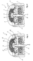
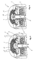
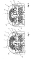
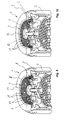
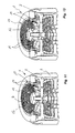
- FIGS. 1 to 26 Different versions of a self-cleaning sanitary installation element 1 are shown.
- the embodiments of the self-cleaning installation element 1 shown here are in the outlet mouthpiece 2 one here not shown further sanitary outlet fitting used.
- Each of the mounting elements 1 has at least one designed as a jet regulator 3 functional unit, which serves to form a homogeneous or pearly soft, ventilated or non-aerated, but especially non-splashing water jet.
- the in the FIGS. 1 to 26 shown installation elements 1 have a filter screen 4 with a centrally arranged here outlet opening 5, wherein the outlet opening 5 has an enlarged compared to the filter openings of the filter screen 4 clear opening cross-section.
- the outlet opening 5 of the filter screen 4 opens into a by-pass channel 6.
- the filter screen 4 is configured funnel-shaped here, wherein the funnel opening of the filter screen 4 serves as an outlet opening 5.
- the funnel-shaped filter screen 4 here has a substantially convex funnel shape, which increasingly tapers in the direction of flow. The funnel-shaped filter screen 4 is thus capable of effectively trapping the dirt particles possibly entrained in the water and accumulating them in the region of the outlet opening 5 at the foot of its funnel shape.
- the outlet opening 5 opens into the by-pass channel 6, through which the collected dirt particles can be removed.
- the outlet opening 5 is arranged in the flow direction in front of and the channel outlet of the by-pass channel 6 downstream of at least one liquid-conducting component of at least one functional unit located in the installation element.
- the by-pass channel 6 can be controlled by means of a valve which is arranged in the region of the outlet opening 5 of the filter screen 4.
- the mounting element 1 Since the valve of the installation elements 1 shown here from its open position under the back pressure of the incoming water against a restoring force can be moved into its closed position, the valve is always held by the inflowing water in its closed position to open only with the interruption of the water flow and closing the outlet fitting such that the accumulated in the outlet opening 5 dirt particles can be removed.
- the mounting element 1 is therefore characterized by a comfortable operation with constant flow characteristics. Since the functioning of a water-bearing component hazardous dirt particles via the by-pass channel 6 during the interruption of the water supply can be dissipated, which is done regularly when closing the water flow controlling outlet fitting, at the same time a low-maintenance and trouble-free operation of the mounting elements 1 shown here the functional units contained therein ensured.
- the jet splitter of the at least one functional unit designed as a jet regulator 3 can be designed either as a perforated plate 7 or as a diffuser 8. While the in FIGS. 1 and 2 illustrated and serving as a beam splitter perforated plate 7 has a plurality of, the inflowing water into individual beams dividing passages 10 has, also provided as a beam splitter diffuser 8 of the in the FIGS. 9 and 10 illustrated jet regulator 3, a baffle plate which surrounds a, interrupted by passage openings 10 peripheral wall 9.
- the at least one functional unit 3 upstream filter openings 11 of the filter screen 4 in comparison to the passage openings 10 of the at least one liquid-carrying component 7, 8 at most equal and preferably smaller clear flow cross-section, so that such dirt particles which the filter openings of the filter screen 4th In any case, pass through the passage openings or through holes 10 of the liquid-carrying component 7, 8 pass.
- valve body 12 has a guide pin 14, which is displaceably guided in corresponding guide openings of the installation element 1.
- the valve body 12 may extend with its guide pin 14 to the downstream in the flow direction components of at least one functional unit 3, as for example in the Figures 1 and 2 is shown. It is also possible that the valve body 12 is guided with its guide pin 14 through the mounting element 1 and projects at least to the water outlet of the mounting element, wherein the projecting portion of the valve body 12 may be configured as a handle 15.
- the designed as a handle 15 and above the mounting element 1 projecting portion not only the respective open or closed position of the valve body 12 recognize, but rather the user if necessary, manually move the valve into its open position by pressurizing the portion of the valve body 12 designed as a handle 15, if a user-initiated cleaning of the installation element 1 appears necessary to him.
- the up to the water outlet of the installation element projecting and designed as a handle 15 portion of the valve body 12 is preferably designed crown-shaped at its free end, so that the dirt in the guide pin 14 dirt particles can also be flushed out when a user the valve body 12 with the Press the finger up and the Ausschwemmö réelle the sleeve-shaped guide pin 14 closes.
- valve body 12 in the FIGS. 1 to 4 and 7 to 12 illustrated built-in elements 1 is designed as a solid and composed of two parts component
- At least one liquid inlet 16 is provided below the valve screen cooperating with the valve seat at the inflow-side end region of the guide pin 14, while the downstream end opening of the tubular guide pin reaching at least as far as the water outlet of the installation element 1 serves as a liquid outlet.
- the valve has a made of elastic material and substantially mushroom or umbrella-shaped valve body 12. While the screen of the in the FIGS. 13 and 14 pictured valve body 12 is placed in the open position upwards, the screen of this elastic valve body by the back pressure of the incoming water against the inherent elasticity of the material used in the, in FIG. 13 shown closed position, everted.
- valve body 12 in the closed position of the valve at the outlet opening 5 bounding and serving as a valve seat edge region of the filter screen 4 tight fit.
- a front screen 17 may be upstream in the flow direction. By such a front screen 17 and comparatively coarse dirt particles can be kept away from the mounting element 1.
- the mounting elements 1 in addition to or instead of a jet regulator 3 may also have a flow rate regulator 18 as a functional unit.
- This flow rate regulator 18 is connected upstream of the jet regulator 3 and its jet splitter configured as a perforated plate 7 in the flow direction. In this case, the operation of the flow rate regulator 18 is ensured by the upstream filter screen 4.
- FIGS. 3 to 6 illustrated jet controller 1 can be configured with manual operation of the cleaning function without a return spring 13.
- the cleaning function is triggered solely by manual pressurization of the handle 15; the cleaning takes place in the thus designed jet regulator 1 practically "on demand”. Due to the omission of the return spring 13, the cost-effective production of the jet regulator 1 is additionally favored.
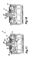
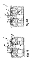
- the installation elements 1 shown there have a guide pin 20 which passes through the outlet opening 5 and projects with its free end of the spigot on the inflow side over the filter screen 4.
- a valve body 12 is slidably guided, which surrounds the guide pin 20 annular.
- a return element 21 is provided made of elastic material, which is connected on the one hand with the valve body 12 and on the other hand with the guide pin 20.
- the restoring element 21 made of elastic material is formed cap-shaped.
- the cap-shaped return elements 21 engages over the guide pin 20 and is integrally formed with its downstream peripheral edge portion of the valve body 12 that the return element 21 is connected at opposite end edges with the valve body 12, while it is supported with its central region on the inflow-side end face of the guide pin 20 ,
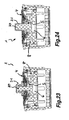
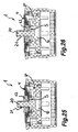
- return element 21 in the FIGS. 15 to 16 . 19 to 20 and 25 to 26 is shown formed as einaitig closed sleeve, which is also cap-shaped return element in the FIGS. 17 to 18 .
- 21 to 22 and 23 to 24 shown installation elements configured at its cap circumference as bellows.
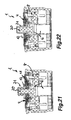
- the by-pass channel in the FIGS. 15 to 16 . 17 to 18 . 23 to 24 and 25 to 26 shown installation elements 1 has its channel outlet on the upstream side of the filter screen 4 subsequent beam breaker.
- the sleeve-shaped by-pass channel 6 of the in FIGS. 19 to 20 and 21 to 22 shown mounting elements 1 continued such that the channel outlet passes through the jet splitter and a downstream flow straightener and is arranged on the downstream side of the mounting element 1.
- the beam splitter is in the FIGS. 15 to 16 and 17 to 18 illustrated installation elements 1 configured as a perforated plate 7, while in the FIGS. 19 to 20 . 21 to 22 . 22 to 23 and 23 to 24 shown installation elements 1 have a diffuser 8 as a beam splitter.
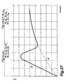
- FIG. 27 shows a typical flow curve, with the installation elements 1 according to the FIGS. 1 to 26 is reachable.
- the dashed line a shows the flow behavior of a jet separator used in the prior art
- the curve b shown in solid line in the low pressure range due to the by-pass effect of the valve still open represents a very steep increase in the flow is then reduced with increasing pressure due to the closing of the valve body 12 and at higher pressure congruent with the curve a, which shows the typical flow behavior of a designed as a jet regulator installation element 1 with befindlichem in the closed position valve.
Landscapes
- Health & Medical Sciences (AREA)
- Life Sciences & Earth Sciences (AREA)
- Engineering & Computer Science (AREA)
- Hydrology & Water Resources (AREA)
- Public Health (AREA)
- Water Supply & Treatment (AREA)
- Nozzles (AREA)
- Bidet-Like Cleaning Device And Other Flush Toilet Accessories (AREA)
- Filtering Materials (AREA)
- Lift Valve (AREA)
- Details Of Valves (AREA)
Priority Applications (1)
| Application Number | Priority Date | Filing Date | Title |
|---|---|---|---|
| PL07856279T PL2097589T3 (pl) | 2006-12-06 | 2007-11-28 | Sanitarny element konstrukcyjny |
Applications Claiming Priority (2)
| Application Number | Priority Date | Filing Date | Title |
|---|---|---|---|
| DE102006057795A DE102006057795B3 (de) | 2006-12-06 | 2006-12-06 | Sanitäres Einbauelement |
| PCT/EP2007/010314 WO2008067936A1 (de) | 2006-12-06 | 2007-11-28 | Sanitäres einbauelement |
Publications (2)
| Publication Number | Publication Date |
|---|---|
| EP2097589A1 EP2097589A1 (de) | 2009-09-09 |
| EP2097589B1 true EP2097589B1 (de) | 2014-10-08 |
Family
ID=38955160
Family Applications (1)
| Application Number | Title | Priority Date | Filing Date |
|---|---|---|---|
| EP07856279.0A Active EP2097589B1 (de) | 2006-12-06 | 2007-11-28 | Sanitäres einbauelement |
Country Status (14)
| Country | Link |
|---|---|
| US (1) | US8308079B2 (pl) |
| EP (1) | EP2097589B1 (pl) |
| JP (1) | JP5361732B2 (pl) |
| KR (2) | KR20150013909A (pl) |
| CN (1) | CN101395323B (pl) |
| AU (1) | AU2007327986B2 (pl) |
| BR (1) | BRPI0707667A8 (pl) |
| DE (2) | DE102006057795B3 (pl) |
| ES (1) | ES2523319T3 (pl) |
| IL (1) | IL193537A (pl) |
| MX (1) | MX2008010848A (pl) |
| PL (1) | PL2097589T3 (pl) |
| RU (1) | RU2442860C2 (pl) |
| WO (1) | WO2008067936A1 (pl) |
Cited By (1)
| Publication number | Priority date | Publication date | Assignee | Title |
|---|---|---|---|---|
| CN104913094A (zh) * | 2014-03-12 | 2015-09-16 | 厦门松霖科技有限公司 | 节水装置 |
Families Citing this family (35)
| Publication number | Priority date | Publication date | Assignee | Title |
|---|---|---|---|---|
| CN101548053B (zh) | 2006-12-06 | 2013-01-16 | 纽珀有限公司 | 卫生用嵌入式元件 |
| US9481986B2 (en) * | 2006-12-06 | 2016-11-01 | Neoperl Gmbh | Sanitary installation element |
| US9139988B2 (en) * | 2009-10-15 | 2015-09-22 | Am Conservation Group, Inc. | Aeration device |
| DE102010012326B4 (de) * | 2010-03-23 | 2015-10-01 | Neoperl Gmbh | Strahlregler |
| DE102010055459A1 (de) | 2010-05-27 | 2011-12-01 | Neoperl Gmbh | Sanitärer Auslaufeinsatz |
| CN102359154B (zh) * | 2011-08-04 | 2013-03-27 | 厦门松霖科技有限公司 | 气水混合起泡器 |
| DE202011105376U1 (de) * | 2011-09-06 | 2012-12-10 | Neoperl Gmbh | Sanitäres Einbauteil |
| CN103132565A (zh) * | 2011-11-28 | 2013-06-05 | 纽珀有限公司 | 卫生嵌入单元 |
| DE102012021361B4 (de) * | 2012-11-02 | 2014-11-06 | Neoperl Gmbh | Strahlregler |
| DE202012010420U1 (de) * | 2012-11-02 | 2014-02-03 | Neoperl Gmbh | Strahlregler |
| DE202013000860U1 (de) * | 2013-01-29 | 2014-05-05 | Neoperl Gmbh | Sanitäres Einbauteil und Komponente einer Sanitärarmatur |
| CN103821201B (zh) * | 2014-03-21 | 2016-08-17 | 厦门松霖科技有限公司 | 带清洁功能的出水装置 |
| DE102014005854B4 (de) * | 2014-04-22 | 2022-11-17 | Neoperl Gmbh | Druckreduzierventil |
| CN105588124A (zh) * | 2014-10-28 | 2016-05-18 | 中国航空工业集团公司西安飞机设计研究所 | 一种油喷多型面火源发生器 |
| DE202015001886U1 (de) * | 2015-03-09 | 2016-06-10 | Neoperl Gmbh | Sanitäre Einsetzeinheit |
| DE202015001754U1 (de) * | 2015-03-09 | 2016-06-10 | Neoperl Gmbh | Durchflussmengenregler-Einheit |
| DE102015017107A1 (de) * | 2015-03-09 | 2016-09-15 | Neoperl Gmbh | Sanitäre Einsetzeinheit |
| CN106031902B (zh) * | 2015-03-17 | 2020-03-17 | 厦门松霖科技股份有限公司 | 一种设有排杂流道的花洒 |
| DE202016001630U1 (de) * | 2016-03-14 | 2017-06-16 | Neoperl Gmbh | Strahlregler |
| US11248368B2 (en) | 2016-04-14 | 2022-02-15 | Delta Faucet Company | Faucet aerator with center stream |
| DE202016003402U1 (de) | 2016-05-28 | 2017-08-30 | Neoperl Gmbh | Sanitäre Einsetzeinheit |
| DE102016006498B4 (de) * | 2016-05-28 | 2018-02-15 | Neoperl Gmbh | Sanitäre Einsetzeinheit |
| DE202016005553U1 (de) * | 2016-09-08 | 2017-12-11 | Neoperl Gmbh | Sanitäre Einsetzeinheit |
| DE102016011168B4 (de) | 2016-09-16 | 2026-02-26 | Neoperl Gmbh | Sanitäre Einheit |
| US10358803B2 (en) * | 2016-09-30 | 2019-07-23 | Toto Ltd. | Spout apparatus |
| USD964514S1 (en) | 2017-03-07 | 2022-09-20 | Neoperl Gmbh | Faucet stream straightener |
| DE102017214571B4 (de) | 2017-08-21 | 2019-02-28 | Hansgrohe Se | Sanitärarmatur mit Wasserführungskanal |
| US11591780B2 (en) * | 2020-04-15 | 2023-02-28 | Yeuu Deng Sanitary Facilities Industrial Co., Ltd. | Faucet aerator |
| DE202020103532U1 (de) * | 2020-06-18 | 2021-09-23 | Neoperl Gmbh | Sanitäres Einsetzteil |
| DE202020103566U1 (de) * | 2020-06-19 | 2021-09-23 | Neoperl Gmbh | Strahlregler |
| CN111827417B (zh) * | 2020-07-07 | 2025-04-18 | 厦门水蜻蜓卫浴科技有限公司 | 一种出水装置 |
| DE202020106451U1 (de) * | 2020-11-10 | 2022-02-16 | Neoperl Gmbh | Strahlregler |
| DE102021127212A1 (de) * | 2021-10-20 | 2023-04-20 | Neoperl Gmbh | Sanitäre Funktionseinheit |
| CN115814967B (zh) * | 2022-11-08 | 2025-12-23 | 杨德会 | 一种多功能卫浴出水装置 |
| DE202022106621U1 (de) * | 2022-11-25 | 2023-11-29 | Neoperl Gmbh | Sanitäres Einbauteil |
Family Cites Families (16)
| Publication number | Priority date | Publication date | Assignee | Title |
|---|---|---|---|---|
| US3104819A (en) * | 1963-09-24 | Spiral screened fluid mixing devices | ||
| US2014063A (en) * | 1934-06-06 | 1935-09-10 | John S Brady | Self-cleaning faucet filter |
| DE2658742C2 (de) * | 1976-12-24 | 1985-08-01 | Dieter Wildfang KG, 7840 Müllheim | Strahlregler |
| US4313564A (en) * | 1979-01-17 | 1982-02-02 | Shames Sidney J | Self-cleaning aerator with noise reduction |
| US4214702A (en) * | 1979-01-17 | 1980-07-29 | Shames | Self-cleaning aerator |
| SU1000523A1 (ru) * | 1981-04-29 | 1983-02-28 | Производственное Объединение "Ростовсантехника" Им.И.Д.Ченцова | Аэратор |
| US4562960A (en) * | 1983-03-14 | 1986-01-07 | Masco Corporation Of Indiana | Pressure responsive aerator |
| DE3642356C2 (de) | 1986-12-11 | 1995-10-05 | Wildfang Dieter Gmbh | Strahlregler |
| AU1926797A (en) * | 1996-10-11 | 1998-05-11 | Dieter Wildfang Gmbh | Sanitary outlet |
| DE29822353U1 (de) * | 1998-01-08 | 1999-05-12 | INGWA Umwelttechnik GmbH, 28832 Achim | Vorrichtung zur Durchflußmengenverringerung von Flüssigkeiten |
| US6241880B1 (en) * | 1999-09-13 | 2001-06-05 | James Yahr | Self-cleaning faucet filter |
| DE10027987B4 (de) * | 2000-06-06 | 2005-12-22 | Neoperl Gmbh | Strahlregler |
| DE102005010551B4 (de) * | 2005-03-04 | 2007-05-16 | Neoperl Gmbh | Sanitäre Funktionseinheit |
| JP4501499B2 (ja) | 2004-03-31 | 2010-07-14 | Toto株式会社 | 吐水切替装置 |
| DE102004044158B3 (de) * | 2004-09-13 | 2006-01-12 | Hansa Metallwerke Ag | Wasserauslaufmundstück mit einem umschaltbaren Strahlreglereinsatz |
| US8925831B2 (en) * | 2005-05-18 | 2015-01-06 | Neoperl Gmbh | Sanitary component, namely jet regulator or jet former for flowing, fluid media, method of producing such a sanitary component and use of a sanitary component |
-
2006
- 2006-12-06 DE DE102006057795A patent/DE102006057795B3/de not_active Expired - Fee Related
-
2007
- 2007-03-02 DE DE202007003264U patent/DE202007003264U1/de not_active Expired - Lifetime
- 2007-11-28 RU RU2008132731/13A patent/RU2442860C2/ru not_active IP Right Cessation
- 2007-11-28 EP EP07856279.0A patent/EP2097589B1/de active Active
- 2007-11-28 JP JP2009539640A patent/JP5361732B2/ja not_active Expired - Fee Related
- 2007-11-28 CN CN2007800078396A patent/CN101395323B/zh not_active Expired - Fee Related
- 2007-11-28 KR KR1020147036525A patent/KR20150013909A/ko not_active Ceased
- 2007-11-28 ES ES07856279.0T patent/ES2523319T3/es active Active
- 2007-11-28 WO PCT/EP2007/010314 patent/WO2008067936A1/de not_active Ceased
- 2007-11-28 PL PL07856279T patent/PL2097589T3/pl unknown
- 2007-11-28 BR BRPI0707667A patent/BRPI0707667A8/pt not_active IP Right Cessation
- 2007-11-28 AU AU2007327986A patent/AU2007327986B2/en not_active Ceased
- 2007-11-28 KR KR1020087024400A patent/KR101516022B1/ko not_active Expired - Fee Related
- 2007-11-28 MX MX2008010848A patent/MX2008010848A/es active IP Right Grant
- 2007-11-28 US US12/296,531 patent/US8308079B2/en not_active Expired - Fee Related
-
2008
- 2008-08-19 IL IL193537A patent/IL193537A/en active IP Right Grant
Cited By (2)
| Publication number | Priority date | Publication date | Assignee | Title |
|---|---|---|---|---|
| CN104913094A (zh) * | 2014-03-12 | 2015-09-16 | 厦门松霖科技有限公司 | 节水装置 |
| CN104913094B (zh) * | 2014-03-12 | 2017-05-10 | 厦门松霖科技有限公司 | 节水装置 |
Also Published As
| Publication number | Publication date |
|---|---|
| IL193537A (en) | 2013-08-29 |
| KR20150013909A (ko) | 2015-02-05 |
| PL2097589T3 (pl) | 2015-03-31 |
| BRPI0707667B1 (pt) | 2017-11-21 |
| BRPI0707667A2 (pt) | 2011-05-10 |
| DE202007003264U1 (de) | 2008-04-17 |
| IL193537A0 (en) | 2009-02-11 |
| AU2007327986A1 (en) | 2008-06-12 |
| BRPI0707667A8 (pt) | 2018-04-24 |
| DE102006057795B3 (de) | 2008-02-21 |
| CN101395323A (zh) | 2009-03-25 |
| WO2008067936A1 (de) | 2008-06-12 |
| AU2007327986B2 (en) | 2013-10-03 |
| RU2008132731A (ru) | 2010-04-27 |
| US20090224067A1 (en) | 2009-09-10 |
| MX2008010848A (es) | 2008-09-05 |
| KR101516022B1 (ko) | 2015-05-04 |
| JP2010511497A (ja) | 2010-04-15 |
| KR20090093791A (ko) | 2009-09-02 |
| US8308079B2 (en) | 2012-11-13 |
| RU2442860C2 (ru) | 2012-02-20 |
| ES2523319T3 (es) | 2014-11-24 |
| JP5361732B2 (ja) | 2013-12-04 |
| CN101395323B (zh) | 2011-11-02 |
| EP2097589A1 (de) | 2009-09-09 |
Similar Documents
| Publication | Publication Date | Title |
|---|---|---|
| EP2097589B1 (de) | Sanitäres einbauelement | |
| EP2100200B1 (de) | Durchflussmengenregler | |
| EP2576925B1 (de) | Sanitärer auslaufeinsatz | |
| EP2087181B1 (de) | Sanitäres einbaulement | |
| EP3199714B1 (de) | Sanitäres auslaufelement | |
| EP3510204B1 (de) | Sanitäre einsetzeinheit | |
| DE102007009717B4 (de) | Durchflussmengenregler | |
| WO2016142060A2 (de) | Sanitäres umschaltventil sowie baugruppe mit einem solchen umschaltventil | |
| DE202006018577U1 (de) | Sanitäres Einbauelement | |
| DE202007002904U1 (de) | Durchflussmengenregler | |
| DE102007010618B4 (de) | Sanitäres Einbauelement | |
| DE102016010842B4 (de) | Sanitäre Einsetzeinheit | |
| DE102016015807B4 (de) | Sanitäre Einsetzeinheit | |
| DE102011112666B4 (de) | Sanitäre Funktionseinheit | |
| DE202005001101U1 (de) | Filtersieb für Wasserauslaufarmaturen | |
| DE102015001383B4 (de) | Sanitäres Auslaufelement | |
| AU2013231013B2 (en) | Sanitory installation element | |
| EP3327208A1 (de) | Sanitäre auslaufeinheit | |
| DE102015001371B3 (de) | Sanitäre Einsetzeinheit | |
| DE102015017072B4 (de) | Sanitäre Einsetzeinheit | |
| DE102011122957B3 (de) | Sanitäres Einbauteil | |
| DE102005003276A1 (de) | Filtersieb für Wasserauslaufarmaturen |
Legal Events
| Date | Code | Title | Description |
|---|---|---|---|
| PUAI | Public reference made under article 153(3) epc to a published international application that has entered the european phase |
Free format text: ORIGINAL CODE: 0009012 |
|
| 17P | Request for examination filed |
Effective date: 20080514 |
|
| AK | Designated contracting states |
Kind code of ref document: A1 Designated state(s): AT BE BG CH CY CZ DE DK EE ES FI FR GB GR HU IE IS IT LI LT LU LV MC MT NL PL PT RO SE SI SK TR |
|
| AX | Request for extension of the european patent |
Extension state: AL BA HR MK RS |
|
| DAX | Request for extension of the european patent (deleted) | ||
| 17Q | First examination report despatched |
Effective date: 20101201 |
|
| GRAP | Despatch of communication of intention to grant a patent |
Free format text: ORIGINAL CODE: EPIDOSNIGR1 |
|
| INTG | Intention to grant announced |
Effective date: 20140630 |
|
| GRAS | Grant fee paid |
Free format text: ORIGINAL CODE: EPIDOSNIGR3 |
|
| GRAA | (expected) grant |
Free format text: ORIGINAL CODE: 0009210 |
|
| AK | Designated contracting states |
Kind code of ref document: B1 Designated state(s): AT BE BG CH CY CZ DE DK EE ES FI FR GB GR HU IE IS IT LI LT LU LV MC MT NL PL PT RO SE SI SK TR |
|
| REG | Reference to a national code |
Ref country code: GB Ref legal event code: FG4D Free format text: NOT ENGLISH |
|
| REG | Reference to a national code |
Ref country code: AT Ref legal event code: REF Ref document number: 690720 Country of ref document: AT Kind code of ref document: T Effective date: 20141015 Ref country code: CH Ref legal event code: EP |
|
| REG | Reference to a national code |
Ref country code: IE Ref legal event code: FG4D Free format text: LANGUAGE OF EP DOCUMENT: GERMAN |
|
| REG | Reference to a national code |
Ref country code: DE Ref legal event code: R096 Ref document number: 502007013511 Country of ref document: DE Effective date: 20141113 |
|
| REG | Reference to a national code |
Ref country code: CH Ref legal event code: NV Representative=s name: HANS RUDOLF GACHNANG PATENTANWALT, CH |
|
| REG | Reference to a national code |
Ref country code: ES Ref legal event code: FG2A Ref document number: 2523319 Country of ref document: ES Kind code of ref document: T3 Effective date: 20141124 |
|
| REG | Reference to a national code |
Ref country code: DE Ref legal event code: R083 Ref document number: 502007013511 Country of ref document: DE |
|
| REG | Reference to a national code |
Ref country code: SE Ref legal event code: TRGR |
|
| REG | Reference to a national code |
Ref country code: NL Ref legal event code: T3 |
|
| REG | Reference to a national code |
Ref country code: LT Ref legal event code: MG4D |
|
| REG | Reference to a national code |
Ref country code: PL Ref legal event code: T3 |
|
| PG25 | Lapsed in a contracting state [announced via postgrant information from national office to epo] |
Ref country code: IS Free format text: LAPSE BECAUSE OF FAILURE TO SUBMIT A TRANSLATION OF THE DESCRIPTION OR TO PAY THE FEE WITHIN THE PRESCRIBED TIME-LIMIT Effective date: 20150208 Ref country code: FI Free format text: LAPSE BECAUSE OF FAILURE TO SUBMIT A TRANSLATION OF THE DESCRIPTION OR TO PAY THE FEE WITHIN THE PRESCRIBED TIME-LIMIT Effective date: 20141008 Ref country code: LT Free format text: LAPSE BECAUSE OF FAILURE TO SUBMIT A TRANSLATION OF THE DESCRIPTION OR TO PAY THE FEE WITHIN THE PRESCRIBED TIME-LIMIT Effective date: 20141008 Ref country code: PT Free format text: LAPSE BECAUSE OF FAILURE TO SUBMIT A TRANSLATION OF THE DESCRIPTION OR TO PAY THE FEE WITHIN THE PRESCRIBED TIME-LIMIT Effective date: 20150209 |
|
| PG25 | Lapsed in a contracting state [announced via postgrant information from national office to epo] |
Ref country code: CY Free format text: LAPSE BECAUSE OF FAILURE TO SUBMIT A TRANSLATION OF THE DESCRIPTION OR TO PAY THE FEE WITHIN THE PRESCRIBED TIME-LIMIT Effective date: 20141008 Ref country code: GR Free format text: LAPSE BECAUSE OF FAILURE TO SUBMIT A TRANSLATION OF THE DESCRIPTION OR TO PAY THE FEE WITHIN THE PRESCRIBED TIME-LIMIT Effective date: 20150109 Ref country code: LV Free format text: LAPSE BECAUSE OF FAILURE TO SUBMIT A TRANSLATION OF THE DESCRIPTION OR TO PAY THE FEE WITHIN THE PRESCRIBED TIME-LIMIT Effective date: 20141008 |
|
| PG25 | Lapsed in a contracting state [announced via postgrant information from national office to epo] |
Ref country code: BE Free format text: LAPSE BECAUSE OF NON-PAYMENT OF DUE FEES Effective date: 20141130 |
|
| REG | Reference to a national code |
Ref country code: DE Ref legal event code: R097 Ref document number: 502007013511 Country of ref document: DE |
|
| PG25 | Lapsed in a contracting state [announced via postgrant information from national office to epo] |
Ref country code: CZ Free format text: LAPSE BECAUSE OF FAILURE TO SUBMIT A TRANSLATION OF THE DESCRIPTION OR TO PAY THE FEE WITHIN THE PRESCRIBED TIME-LIMIT Effective date: 20141008 Ref country code: MC Free format text: LAPSE BECAUSE OF FAILURE TO SUBMIT A TRANSLATION OF THE DESCRIPTION OR TO PAY THE FEE WITHIN THE PRESCRIBED TIME-LIMIT Effective date: 20141008 Ref country code: EE Free format text: LAPSE BECAUSE OF FAILURE TO SUBMIT A TRANSLATION OF THE DESCRIPTION OR TO PAY THE FEE WITHIN THE PRESCRIBED TIME-LIMIT Effective date: 20141008 Ref country code: RO Free format text: LAPSE BECAUSE OF FAILURE TO SUBMIT A TRANSLATION OF THE DESCRIPTION OR TO PAY THE FEE WITHIN THE PRESCRIBED TIME-LIMIT Effective date: 20141008 Ref country code: DK Free format text: LAPSE BECAUSE OF FAILURE TO SUBMIT A TRANSLATION OF THE DESCRIPTION OR TO PAY THE FEE WITHIN THE PRESCRIBED TIME-LIMIT Effective date: 20141008 Ref country code: SK Free format text: LAPSE BECAUSE OF FAILURE TO SUBMIT A TRANSLATION OF THE DESCRIPTION OR TO PAY THE FEE WITHIN THE PRESCRIBED TIME-LIMIT Effective date: 20141008 |
|
| PLBE | No opposition filed within time limit |
Free format text: ORIGINAL CODE: 0009261 |
|
| STAA | Information on the status of an ep patent application or granted ep patent |
Free format text: STATUS: NO OPPOSITION FILED WITHIN TIME LIMIT |
|
| REG | Reference to a national code |
Ref country code: IE Ref legal event code: MM4A |
|
| 26N | No opposition filed |
Effective date: 20150709 |
|
| PG25 | Lapsed in a contracting state [announced via postgrant information from national office to epo] |
Ref country code: IE Free format text: LAPSE BECAUSE OF NON-PAYMENT OF DUE FEES Effective date: 20141128 |
|
| REG | Reference to a national code |
Ref country code: FR Ref legal event code: PLFP Year of fee payment: 9 |
|
| PG25 | Lapsed in a contracting state [announced via postgrant information from national office to epo] |
Ref country code: SI Free format text: LAPSE BECAUSE OF FAILURE TO SUBMIT A TRANSLATION OF THE DESCRIPTION OR TO PAY THE FEE WITHIN THE PRESCRIBED TIME-LIMIT Effective date: 20141008 |
|
| PG25 | Lapsed in a contracting state [announced via postgrant information from national office to epo] |
Ref country code: BG Free format text: LAPSE BECAUSE OF FAILURE TO SUBMIT A TRANSLATION OF THE DESCRIPTION OR TO PAY THE FEE WITHIN THE PRESCRIBED TIME-LIMIT Effective date: 20141008 |
|
| PG25 | Lapsed in a contracting state [announced via postgrant information from national office to epo] |
Ref country code: HU Free format text: LAPSE BECAUSE OF FAILURE TO SUBMIT A TRANSLATION OF THE DESCRIPTION OR TO PAY THE FEE WITHIN THE PRESCRIBED TIME-LIMIT; INVALID AB INITIO Effective date: 20071128 Ref country code: MT Free format text: LAPSE BECAUSE OF FAILURE TO SUBMIT A TRANSLATION OF THE DESCRIPTION OR TO PAY THE FEE WITHIN THE PRESCRIBED TIME-LIMIT Effective date: 20141008 Ref country code: LU Free format text: LAPSE BECAUSE OF NON-PAYMENT OF DUE FEES Effective date: 20141128 |
|
| REG | Reference to a national code |
Ref country code: FR Ref legal event code: PLFP Year of fee payment: 10 |
|
| PGFP | Annual fee paid to national office [announced via postgrant information from national office to epo] |
Ref country code: GB Payment date: 20170908 Year of fee payment: 11 |
|
| REG | Reference to a national code |
Ref country code: FR Ref legal event code: PLFP Year of fee payment: 11 |
|
| PGFP | Annual fee paid to national office [announced via postgrant information from national office to epo] |
Ref country code: NL Payment date: 20171122 Year of fee payment: 11 |
|
| REG | Reference to a national code |
Ref country code: NL Ref legal event code: MM Effective date: 20181201 |
|
| GBPC | Gb: european patent ceased through non-payment of renewal fee |
Effective date: 20181128 |
|
| PG25 | Lapsed in a contracting state [announced via postgrant information from national office to epo] |
Ref country code: NL Free format text: LAPSE BECAUSE OF NON-PAYMENT OF DUE FEES Effective date: 20181201 |
|
| PG25 | Lapsed in a contracting state [announced via postgrant information from national office to epo] |
Ref country code: GB Free format text: LAPSE BECAUSE OF NON-PAYMENT OF DUE FEES Effective date: 20181128 |
|
| PGFP | Annual fee paid to national office [announced via postgrant information from national office to epo] |
Ref country code: ES Payment date: 20191216 Year of fee payment: 13 |
|
| REG | Reference to a national code |
Ref country code: ES Ref legal event code: FD2A Effective date: 20220207 |
|
| PG25 | Lapsed in a contracting state [announced via postgrant information from national office to epo] |
Ref country code: ES Free format text: LAPSE BECAUSE OF NON-PAYMENT OF DUE FEES Effective date: 20201129 |
|
| PGFP | Annual fee paid to national office [announced via postgrant information from national office to epo] |
Ref country code: SE Payment date: 20221122 Year of fee payment: 16 |
|
| PGFP | Annual fee paid to national office [announced via postgrant information from national office to epo] |
Ref country code: PL Payment date: 20221116 Year of fee payment: 16 |
|
| PGFP | Annual fee paid to national office [announced via postgrant information from national office to epo] |
Ref country code: TR Payment date: 20231121 Year of fee payment: 17 Ref country code: IT Payment date: 20231130 Year of fee payment: 17 Ref country code: FR Payment date: 20231124 Year of fee payment: 17 Ref country code: DE Payment date: 20231128 Year of fee payment: 17 Ref country code: CH Payment date: 20231201 Year of fee payment: 17 Ref country code: AT Payment date: 20231117 Year of fee payment: 17 |
|
| REG | Reference to a national code |
Ref country code: SE Ref legal event code: EUG |
|
| PG25 | Lapsed in a contracting state [announced via postgrant information from national office to epo] |
Ref country code: SE Free format text: LAPSE BECAUSE OF NON-PAYMENT OF DUE FEES Effective date: 20231129 |
|
| PG25 | Lapsed in a contracting state [announced via postgrant information from national office to epo] |
Ref country code: PL Free format text: LAPSE BECAUSE OF NON-PAYMENT OF DUE FEES Effective date: 20231128 |
|
| REG | Reference to a national code |
Ref country code: DE Ref legal event code: R119 Ref document number: 502007013511 Country of ref document: DE |
|
| REG | Reference to a national code |
Ref country code: CH Ref legal event code: PL |
|
| REG | Reference to a national code |
Ref country code: AT Ref legal event code: MM01 Ref document number: 690720 Country of ref document: AT Kind code of ref document: T Effective date: 20241128 Ref country code: CH Ref legal event code: PL |
|
| PG25 | Lapsed in a contracting state [announced via postgrant information from national office to epo] |
Ref country code: CH Free format text: LAPSE BECAUSE OF NON-PAYMENT OF DUE FEES Effective date: 20241130 |
|
| PG25 | Lapsed in a contracting state [announced via postgrant information from national office to epo] |
Ref country code: AT Free format text: LAPSE BECAUSE OF NON-PAYMENT OF DUE FEES Effective date: 20241128 |
|
| PG25 | Lapsed in a contracting state [announced via postgrant information from national office to epo] |
Ref country code: DE Free format text: LAPSE BECAUSE OF NON-PAYMENT OF DUE FEES Effective date: 20250603 |
|
| PG25 | Lapsed in a contracting state [announced via postgrant information from national office to epo] |
Ref country code: IT Free format text: LAPSE BECAUSE OF NON-PAYMENT OF DUE FEES Effective date: 20241128 |
|
| PG25 | Lapsed in a contracting state [announced via postgrant information from national office to epo] |
Ref country code: FR Free format text: LAPSE BECAUSE OF NON-PAYMENT OF DUE FEES Effective date: 20241130 |