EP2097589B1 - Sanitory installation element - Google Patents
Sanitory installation element Download PDFInfo
- Publication number
- EP2097589B1 EP2097589B1 EP07856279.0A EP07856279A EP2097589B1 EP 2097589 B1 EP2097589 B1 EP 2097589B1 EP 07856279 A EP07856279 A EP 07856279A EP 2097589 B1 EP2097589 B1 EP 2097589B1
- Authority
- EP
- European Patent Office
- Prior art keywords
- insert element
- element according
- valve body
- valve
- filter screen
- Prior art date
- Legal status (The legal status is an assumption and is not a legal conclusion. Google has not performed a legal analysis and makes no representation as to the accuracy of the status listed.)
- Active
Links
- 238000009434 installation Methods 0.000 title description 63
- XLYOFNOQVPJJNP-UHFFFAOYSA-N water Substances O XLYOFNOQVPJJNP-UHFFFAOYSA-N 0.000 claims description 60
- 238000004140 cleaning Methods 0.000 claims description 23
- 239000013013 elastic material Substances 0.000 claims description 12
- 238000011144 upstream manufacturing Methods 0.000 claims description 12
- 239000007788 liquid Substances 0.000 claims description 8
- 238000007789 sealing Methods 0.000 claims description 2
- 239000002245 particle Substances 0.000 description 25
- 239000000463 material Substances 0.000 description 5
- 230000002093 peripheral effect Effects 0.000 description 4
- 238000001595 flow curve Methods 0.000 description 3
- 231100001261 hazardous Toxicity 0.000 description 3
- 238000012423 maintenance Methods 0.000 description 3
- 230000000694 effects Effects 0.000 description 2
- 239000007787 solid Substances 0.000 description 2
- 235000001674 Agaricus brunnescens Nutrition 0.000 description 1
- 241001295925 Gegenes Species 0.000 description 1
- 230000003247 decreasing effect Effects 0.000 description 1
- 239000012530 fluid Substances 0.000 description 1
- 238000004519 manufacturing process Methods 0.000 description 1
- 238000011045 prefiltration Methods 0.000 description 1
- 239000008234 soft water Substances 0.000 description 1
- 230000001960 triggered effect Effects 0.000 description 1
Images


Classifications
-
- E—FIXED CONSTRUCTIONS
- E03—WATER SUPPLY; SEWERAGE
- E03C—DOMESTIC PLUMBING INSTALLATIONS FOR FRESH WATER OR WASTE WATER; SINKS
- E03C1/00—Domestic plumbing installations for fresh water or waste water; Sinks
- E03C1/02—Plumbing installations for fresh water
- E03C1/08—Jet regulators or jet guides, e.g. anti-splash devices
- E03C1/084—Jet regulators with aerating means
-
- B—PERFORMING OPERATIONS; TRANSPORTING
- B05—SPRAYING OR ATOMISING IN GENERAL; APPLYING FLUENT MATERIALS TO SURFACES, IN GENERAL
- B05B—SPRAYING APPARATUS; ATOMISING APPARATUS; NOZZLES
- B05B1/00—Nozzles, spray heads or other outlets, with or without auxiliary devices such as valves, heating means
-
- E—FIXED CONSTRUCTIONS
- E03—WATER SUPPLY; SEWERAGE
- E03C—DOMESTIC PLUMBING INSTALLATIONS FOR FRESH WATER OR WASTE WATER; SINKS
- E03C1/00—Domestic plumbing installations for fresh water or waste water; Sinks
- E03C1/02—Plumbing installations for fresh water
- E03C1/08—Jet regulators or jet guides, e.g. anti-splash devices
- E03C1/086—Jet regulators or jet guides, easily mountable on the outlet of taps
-
- B—PERFORMING OPERATIONS; TRANSPORTING
- B01—PHYSICAL OR CHEMICAL PROCESSES OR APPARATUS IN GENERAL
- B01D—SEPARATION
- B01D35/00—Filtering devices having features not specifically covered by groups B01D24/00 - B01D33/00, or for applications not specifically covered by groups B01D24/00 - B01D33/00; Auxiliary devices for filtration; Filter housing constructions
- B01D35/02—Filters adapted for location in special places, e.g. pipe-lines, pumps, stop-cocks
-
- Y—GENERAL TAGGING OF NEW TECHNOLOGICAL DEVELOPMENTS; GENERAL TAGGING OF CROSS-SECTIONAL TECHNOLOGIES SPANNING OVER SEVERAL SECTIONS OF THE IPC; TECHNICAL SUBJECTS COVERED BY FORMER USPC CROSS-REFERENCE ART COLLECTIONS [XRACs] AND DIGESTS
- Y10—TECHNICAL SUBJECTS COVERED BY FORMER USPC
- Y10S—TECHNICAL SUBJECTS COVERED BY FORMER USPC CROSS-REFERENCE ART COLLECTIONS [XRACs] AND DIGESTS
- Y10S261/00—Gas and liquid contact apparatus
- Y10S261/22—Faucet aerators
Definitions
- the invention relates to a sanitary installation element with at least one by-pass channel, to which a valve is assigned, in the open position of which at least one by-pass channel is connected.
- Sanitary installation elements which are designed as a jet regulator which can be inserted into the outlet mouthpiece of a sanitary outlet fitting are already known.
- Such jet regulators which are provided to produce a homogeneous and pearly-soft water jet, have in the housing interior of their installation housing a jet splitter, which can be configured as a diffuser or as a perforated plate. While the perforated plate has a plurality of flow holes each producing a single jet, the diffuser has a baffle plate which is delimited by a wall section interrupted by passage openings.
- the known installation element is configured as a jet regulator insert, which can be switched between a powerful cleaning jet and a soft ventilated overall jet.
- the previously known jet regulator insert has for this purpose a central cleaning jet channel, which surrounds an annular flow chamber with a multiplicity of water outlet nozzles.
- the flow chamber provided for generating the soft ventilated overall jet has an inflow opening which can be controlled with a valve biased into its closed position in such a way that the inflowing water opens the valve by a predeterminable backpressure of the water.
- the cleaning jet can be advantageously used, for example, for cleaning a razor
- a soft jet composed of a plurality of individual jets is produced when the valve is opened as a result of the water pressure. Since the so-called soft jet includes the powerful cleaning jet, it always results even with a corresponding water pressure a comparatively uncomfortable perceived and centrally splashing overall jet.
- the cleaning jet of the prior art jet regulator is also provided only for external cleaning purposes, but not for self-cleaning of the jet regulator for the purpose of maintaining its intended functions.
- the installation element has a filter with at least one outlet opening, which outlet has a larger compared to the filter openings of the filter screen clear opening cross-section that the at least one outlet opening in the at least opens a by-pass channel, and that the outlet opening in the flow direction before and the channel outlet of the at least one by-pass channel downstream of at least one liquid-conducting component of at least one functional unit located in the installation element is arranged.
- the installation element according to the invention has a filter screen with at least one outlet opening, which intercepts the dirt particles entrained in the water and can accumulate in order to discharge them via its outlet opening.
- the outlet opening of this filter sieve has an enlarged opening cross-section which is larger in comparison to the filter openings of the filter sieve.
- the at least one outlet opening opens into the at least one by-pass channel, through which the accumulated dirt particles can be removed.
- the at least one outlet opening of the filter screen is arranged in the flow direction before and the channel outlet of the by-pass channel downstream of at least one liquid-conducting component of at least one functional unit located in the installation element.
- the installation element according to the invention is therefore characterized by a comfortable operation with constant flow velocities. Since the functioning of a water-bearing component potentially hazardous dirt particles can be dissipated via the by-pass channel during the interruption of water supply, a low-maintenance and trouble-free operation of the installation element according to the invention and the functional units therein is ensured simultaneously.
- the at least one valve is movable from its open position under the back pressure of the inflowing water in its closed position.
- a preferred and particularly advantageous embodiment according to the invention provides that the installation element is designed to be self-cleaning and that for this purpose the at least one valve under the back pressure of the inflowing water is movable against a restoring force in its closed position.
- the valve is basically held in its open position by the restoring force. Since the valve is movable from its open position under the back pressure of the incoming water against the restoring force in its closed position, the valve is held by the inflowing water in its closed position, only with the interruption of the flow of water under closing the outlet fitting open so that the accumulated dirt particles can be removed.
- the functioning of a water-bearing component hazardous dirt particles can be removed via the by-pass channel during the interruption of the water supply, which is done regularly when closing the water flow controlling outlet fitting.
- a preferred embodiment according to the invention provides that the installation element has a jet regulator as a functional unit and that a jet splitter is provided as at least one of the liquid-conducting components. Since just the jet splitter of a jet regulator with its comparatively small flow cross-sections is endangered by dirt particles entrained in the water, the built-in element according to the invention with its self-cleaning properties can be used advantageously in conjunction with a jet regulator.
- the jet splitter can be configured as a perforated plate or as a diffuser.
- the filter openings of the filter screen have an equal or smaller clear flow cross-section compared to the flow openings of the at least one liquid-conducting component. In this way, it is ensured that such dirt particles, which may have passed through the filter openings of the filter screen, can also pass through the flow openings of the jet breaker.
- the at least one functional unit is connected downstream of the filter openings of the filter in the flow direction.
- the purified by the filter openings of the filter water jet is always supplied to the at least one functional unit.
- a preferred embodiment according to the invention provides that at least one valve has a valve body, which is displaceably guided in the installation element against a restoring force.
- a particularly advantageous development according to the invention provides that a portion of the valve body passed through the installation element protrudes at least approximately as far as the water outlet of the installation element and is configured as a handle for manual actuation of the valve.
- the protruding over the water outlet of the installation member portion of the valve body can not only recognize the respective operating position of the valve, but the user can if necessary beyond the automatic self-cleaning of the installation element according to the invention also trigger further self-cleaning operations, if he the valve body at the designed as a handle portion Need moved into its open position.
- valve body is mushroom-shaped or dish-shaped.
- valve body has a guide pin displaceably guided in the installation element.
- This guide pin can be configured solid and guided in corresponding guide openings of the mounting element be.
- the guide pin is tubular, that the tube interior of the guide pin is designed as a by-pass channel, and that at least one liquid inlet in the inflow-side end region of the guide pin and at least one liquid outlet in the downstream end region of the guide pin is.
- the dirt particles are passed over the tube interior of the tubular guide pin formed on the liquid-conducting component of the functional unit. If the tubular guide pin projects beyond the water outlet of the installation element according to the invention, the dirt particles are conveyed directly to the outside without being able to affect even one of the functional units.
- a particularly simple embodiment according to the invention provides that the outflow-side and preferably over the installation element projecting end opening of the guide pin is designed as a liquid outlet.
- valve body is designed to be elastic at least in a umbrella-shaped portion and outer peripheral side has a circumferential sealing lip and that the umbrella-shaped portion is movable from an open position against the elasticity of the elastic material in a closed position.
- the elastically configured umbrella-shaped portion of such a valve body can be everted by the back pressure of the inflowing water such that the valve moves from its open position to its closed position. With decreasing back pressure of the water, the umbrella-shaped portion of the valve body can evert from its closed position to the open position due to the inherent elasticity of the material. It is particularly advantageous if the edge region of the filter screen delimiting the outlet opening is designed as a valve seat cooperating with the valve body.
- the installation element in the flow direction at least one attachment screen is connected upstream.
- Such a front screen causes prefiltration of the incoming water before the water can then pass through the filter screen.
- the installation element has a jet regulator and a preferably upstream flow rate regulator as functional units.
- a preferred embodiment according to the invention provides that the filter screen is funnel-shaped and that the funnel opening of the filter screen serves as an outlet opening.
- the funnel-shaped filter screen may have a substantially convex or concave funnel shape.
- valve body of the by-pass channel associated valve can be moved against the restoring force of a return spring from its open position to the closed position.
- Another, particularly advantageous embodiment according to the invention provides that the valve body is displaceably guided on a guide pin protruding beyond the attachment or filter screen and that at least one return element of elastic material is provided, which is connected on the one hand to the valve body and on the other hand to the guide pin is.
- valve body In order to be able to guide the valve body particularly securely on the guide pin, it is expedient if the valve body surrounds the guide pin in an annular manner.
- valve body on the one hand and its associated restoring element on the other hand form an inseparable functional unit when the restoring element is integrally molded with opposite end edges on the valve body and when the restoring element is supported with its central region on the inflow-side end side of the guide pin.
- the restoring element can be fastened to the valve body practically in the manner of a spring-bellows or suspenders.
- a particularly simple and advantageous embodiment according to the invention provides that the restoring element engages over the guide pin in the shape of a cap and that the return element is integrally formed with its downstream peripheral edge region integrally with the valve body.
- a preferred embodiment according to the invention therefore provides that the valve body is guided displaceably on the guide pin substantially by the elastically yielding cap circumference of the return element.
- the return element connected to the valve body can be made of hard elastic material and / or allow a longer adjustment of the valve body when the return element has a cap circumference designed as a bellows.
- FIGS. 1 to 26 Different versions of a self-cleaning sanitary installation element 1 are shown.
- the embodiments of the self-cleaning installation element 1 shown here are in the outlet mouthpiece 2 one here not shown further sanitary outlet fitting used.
- Each of the mounting elements 1 has at least one designed as a jet regulator 3 functional unit, which serves to form a homogeneous or pearly soft, ventilated or non-aerated, but especially non-splashing water jet.
- the in the FIGS. 1 to 26 shown installation elements 1 have a filter screen 4 with a centrally arranged here outlet opening 5, wherein the outlet opening 5 has an enlarged compared to the filter openings of the filter screen 4 clear opening cross-section.
- the outlet opening 5 of the filter screen 4 opens into a by-pass channel 6.
- the filter screen 4 is configured funnel-shaped here, wherein the funnel opening of the filter screen 4 serves as an outlet opening 5.
- the funnel-shaped filter screen 4 here has a substantially convex funnel shape, which increasingly tapers in the direction of flow. The funnel-shaped filter screen 4 is thus capable of effectively trapping the dirt particles possibly entrained in the water and accumulating them in the region of the outlet opening 5 at the foot of its funnel shape.
- the outlet opening 5 opens into the by-pass channel 6, through which the collected dirt particles can be removed.
- the outlet opening 5 is arranged in the flow direction in front of and the channel outlet of the by-pass channel 6 downstream of at least one liquid-conducting component of at least one functional unit located in the installation element.
- the by-pass channel 6 can be controlled by means of a valve which is arranged in the region of the outlet opening 5 of the filter screen 4.
- the mounting element 1 Since the valve of the installation elements 1 shown here from its open position under the back pressure of the incoming water against a restoring force can be moved into its closed position, the valve is always held by the inflowing water in its closed position to open only with the interruption of the water flow and closing the outlet fitting such that the accumulated in the outlet opening 5 dirt particles can be removed.
- the mounting element 1 is therefore characterized by a comfortable operation with constant flow characteristics. Since the functioning of a water-bearing component hazardous dirt particles via the by-pass channel 6 during the interruption of the water supply can be dissipated, which is done regularly when closing the water flow controlling outlet fitting, at the same time a low-maintenance and trouble-free operation of the mounting elements 1 shown here the functional units contained therein ensured.
- the jet splitter of the at least one functional unit designed as a jet regulator 3 can be designed either as a perforated plate 7 or as a diffuser 8. While the in FIGS. 1 and 2 illustrated and serving as a beam splitter perforated plate 7 has a plurality of, the inflowing water into individual beams dividing passages 10 has, also provided as a beam splitter diffuser 8 of the in the FIGS. 9 and 10 illustrated jet regulator 3, a baffle plate which surrounds a, interrupted by passage openings 10 peripheral wall 9.
- the at least one functional unit 3 upstream filter openings 11 of the filter screen 4 in comparison to the passage openings 10 of the at least one liquid-carrying component 7, 8 at most equal and preferably smaller clear flow cross-section, so that such dirt particles which the filter openings of the filter screen 4th In any case, pass through the passage openings or through holes 10 of the liquid-carrying component 7, 8 pass.
- valve body 12 has a guide pin 14, which is displaceably guided in corresponding guide openings of the installation element 1.
- the valve body 12 may extend with its guide pin 14 to the downstream in the flow direction components of at least one functional unit 3, as for example in the Figures 1 and 2 is shown. It is also possible that the valve body 12 is guided with its guide pin 14 through the mounting element 1 and projects at least to the water outlet of the mounting element, wherein the projecting portion of the valve body 12 may be configured as a handle 15.
- the designed as a handle 15 and above the mounting element 1 projecting portion not only the respective open or closed position of the valve body 12 recognize, but rather the user if necessary, manually move the valve into its open position by pressurizing the portion of the valve body 12 designed as a handle 15, if a user-initiated cleaning of the installation element 1 appears necessary to him.
- the up to the water outlet of the installation element projecting and designed as a handle 15 portion of the valve body 12 is preferably designed crown-shaped at its free end, so that the dirt in the guide pin 14 dirt particles can also be flushed out when a user the valve body 12 with the Press the finger up and the Ausschwemmö réelle the sleeve-shaped guide pin 14 closes.
- valve body 12 in the FIGS. 1 to 4 and 7 to 12 illustrated built-in elements 1 is designed as a solid and composed of two parts component
- At least one liquid inlet 16 is provided below the valve screen cooperating with the valve seat at the inflow-side end region of the guide pin 14, while the downstream end opening of the tubular guide pin reaching at least as far as the water outlet of the installation element 1 serves as a liquid outlet.
- the valve has a made of elastic material and substantially mushroom or umbrella-shaped valve body 12. While the screen of the in the FIGS. 13 and 14 pictured valve body 12 is placed in the open position upwards, the screen of this elastic valve body by the back pressure of the incoming water against the inherent elasticity of the material used in the, in FIG. 13 shown closed position, everted.
- valve body 12 in the closed position of the valve at the outlet opening 5 bounding and serving as a valve seat edge region of the filter screen 4 tight fit.
- a front screen 17 may be upstream in the flow direction. By such a front screen 17 and comparatively coarse dirt particles can be kept away from the mounting element 1.
- the mounting elements 1 in addition to or instead of a jet regulator 3 may also have a flow rate regulator 18 as a functional unit.
- This flow rate regulator 18 is connected upstream of the jet regulator 3 and its jet splitter configured as a perforated plate 7 in the flow direction. In this case, the operation of the flow rate regulator 18 is ensured by the upstream filter screen 4.
- FIGS. 3 to 6 illustrated jet controller 1 can be configured with manual operation of the cleaning function without a return spring 13.
- the cleaning function is triggered solely by manual pressurization of the handle 15; the cleaning takes place in the thus designed jet regulator 1 practically "on demand”. Due to the omission of the return spring 13, the cost-effective production of the jet regulator 1 is additionally favored.
- the installation elements 1 shown there have a guide pin 20 which passes through the outlet opening 5 and projects with its free end of the spigot on the inflow side over the filter screen 4.
- a valve body 12 is slidably guided, which surrounds the guide pin 20 annular.
- a return element 21 is provided made of elastic material, which is connected on the one hand with the valve body 12 and on the other hand with the guide pin 20.
- the restoring element 21 made of elastic material is formed cap-shaped.
- the cap-shaped return elements 21 engages over the guide pin 20 and is integrally formed with its downstream peripheral edge portion of the valve body 12 that the return element 21 is connected at opposite end edges with the valve body 12, while it is supported with its central region on the inflow-side end face of the guide pin 20 ,
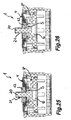
- return element 21 in the FIGS. 15 to 16 . 19 to 20 and 25 to 26 is shown formed as einaitig closed sleeve, which is also cap-shaped return element in the FIGS. 17 to 18 .
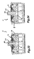
- 21 to 22 and 23 to 24 shown installation elements configured at its cap circumference as bellows.
- the by-pass channel in the FIGS. 15 to 16 . 17 to 18 . 23 to 24 and 25 to 26 shown installation elements 1 has its channel outlet on the upstream side of the filter screen 4 subsequent beam breaker.
- the sleeve-shaped by-pass channel 6 of the in FIGS. 19 to 20 and 21 to 22 shown mounting elements 1 continued such that the channel outlet passes through the jet splitter and a downstream flow straightener and is arranged on the downstream side of the mounting element 1.
- the beam splitter is in the FIGS. 15 to 16 and 17 to 18 illustrated installation elements 1 configured as a perforated plate 7, while in the FIGS. 19 to 20 . 21 to 22 . 22 to 23 and 23 to 24 shown installation elements 1 have a diffuser 8 as a beam splitter.
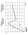
- FIG. 27 shows a typical flow curve, with the installation elements 1 according to the FIGS. 1 to 26 is reachable.
- the dashed line a shows the flow behavior of a jet separator used in the prior art
- the curve b shown in solid line in the low pressure range due to the by-pass effect of the valve still open represents a very steep increase in the flow is then reduced with increasing pressure due to the closing of the valve body 12 and at higher pressure congruent with the curve a, which shows the typical flow behavior of a designed as a jet regulator installation element 1 with befindlichem in the closed position valve.
Landscapes
- Health & Medical Sciences (AREA)
- Life Sciences & Earth Sciences (AREA)
- Engineering & Computer Science (AREA)
- Hydrology & Water Resources (AREA)
- Public Health (AREA)
- Water Supply & Treatment (AREA)
- Nozzles (AREA)
- Bidet-Like Cleaning Device And Other Flush Toilet Accessories (AREA)
- Details Of Valves (AREA)
- Filtering Materials (AREA)
- Lift Valve (AREA)
Description
Die Erfindung betrifft ein sanitäres Einbauelement mit zumindest einem By-Pass-Kanal, dem ein Ventil zugeordnet ist, in dessen Offenstellung der zumindest eine By-Pass-Kanal zugeschaltet ist.The invention relates to a sanitary installation element with at least one by-pass channel, to which a valve is assigned, in the open position of which at least one by-pass channel is connected.
Man kennt bereits sanitäre Einbauelemente, die als ein in das Auslaufmundstück einer sanitären Auslaufarmatur einsetzbarer Strahlreglers ausgestaltet sind. Solche Strahlregler, die zur Erzeugung eines homogenen und perlend-weichen Wasserstrahls vorgesehen sind, weisen im Gehäuseinneren ihres Einbaugehäuses einen Strahlzerleger auf, der als ein Diffusor oder als eine Lochplatte ausgestaltet sein kann. Während die Lochplatte eine Vielzahl, jeweils einen Einzelstrahl erzeugender Durchflusslöcher hat, weist der Diffusor eine Prallplatte auf, die von einem durch Durchtrittsöffnungen unterbrochenen Wandungsabschnitt umgrenzt ist. Bei diesen vorbekannten Einbauelementen besteht die Gefahr, dass im Wasser mitgeführte Schmutzpartikel die vergleichsweise kleinen Durchflussquerschnitte der Lochplatte oder des Diffusors verstopfen und somit die Funktion der in den vorbekannten Einbauelementen vorgesehenen Funktionseinheiten beeinträchtigen können.Sanitary installation elements which are designed as a jet regulator which can be inserted into the outlet mouthpiece of a sanitary outlet fitting are already known. Such jet regulators, which are provided to produce a homogeneous and pearly-soft water jet, have in the housing interior of their installation housing a jet splitter, which can be configured as a diffuser or as a perforated plate. While the perforated plate has a plurality of flow holes each producing a single jet, the diffuser has a baffle plate which is delimited by a wall section interrupted by passage openings. In these known installation elements, there is a risk that entrained in the water dirt particles clog the comparatively small flow cross-sections of the perforated plate or the diffuser and thus may affect the function of the provided in the prior art mounting elements functional units.
Man hat daher auch bereits ein selbstreinigendes und als Strahlregler ausgestaltetes sanitäres Einbauelement geschaffen (vgl.
Aus der
Es besteht daher die Aufgabe, ein sanitäres Einbauelement der eingangs erwähnten Art zu schaffen, dass sich durch die störungsfreie und wartungsarme Funktionsweise der darin befindlichen Funktionseinheiten auszeichnet und unabhängig vom Wasserdruck einen homogenen Wasserstrahl zu formen vermag.It is therefore an object to provide a sanitary installation element of the type mentioned that is characterized by the trouble-free and low-maintenance operation of the functional units contained therein and is able to form a homogeneous water jet regardless of the water pressure.
Die erfindungsgemäße Lösung dieser Aufgabe besteht bei dem Einbauelement der eingangs erwähnten Art insbesondere darin, dass das Einbauelement ein Filtersieb mit wenigstens einer Auslassöffnung hat, welche Auslassöffnung einen im Vergleich zu den Filteröffnungen des Filtersiebes vergrößerten lichten Öffnungsquerschnitt aufweist, dass die wenigstens eine Auslassöffnung in den zumindest einen By-Pass-Kanal mündet, und dass die Auslassöffnung in Strömungsrichtung vor und der Kanalauslass des zumindest einen By-Pass-Kanals in Strömungsrichtung hinter mindestens einem flüssigkeitsführenden Bestandteil wenigstens einer im Einbauelement befindlichen Funktionseinheit angeordnet ist.The inventive solution to this problem is in the installation element of the type mentioned in particular that the installation element has a filter with at least one outlet opening, which outlet has a larger compared to the filter openings of the filter screen clear opening cross-section that the at least one outlet opening in the at least opens a by-pass channel, and that the outlet opening in the flow direction before and the channel outlet of the at least one by-pass channel downstream of at least one liquid-conducting component of at least one functional unit located in the installation element is arranged.
Das erfindungsgemäße Einbauelement weist ein Filtersieb mit wenigstens einer Auslassöffnung auf, das die im Wasser mitgeführten Schmutzpartikel abfängt und ansammeln kann, um diese über seine Auslassöffnung auszutragen. Um diese Schmutzpartikel von der Zuströmseite des Filtersiebes aus austragen zu können, weist die Auslassöffnung dieses Filtersiebes einen im Vergleich zu den Filteröffnungen des Filtersiebes vergrößerten lichten Öffnungsquerschnitt auf. Die wenigstens eine Auslassöffnung mündet in dem zumindest einen By-Pass-Kanal, durch den die angesammelten Schmutzpartikel abgeführt werden können. Dabei ist die wenigstens eine Auslassöffnung des Filtersiebs in Strömungsrichtung vor und der Kanalauslass des By-Pass-Kanals in Strömungsrichtung hinter mindestens einem flüssigkeitsführenden Bestandteil wenigstens einer im Einbauelement befindlichen Funktionseinheit angeordnet. Das erfindungsgemäße Einbauelement zeichnet sich daher durch eine komfortable Funktionsweise mit gleichbleibenden Strömungsgeschwindigkeiten aus. Da die die Funktionsweise eines wasserführenden Bestandteils eventuell gefährdenden Schmutzpartikel über den By-Pass-Kanal während der Unterbrechung der Wasserzufuhr abgeführt werden können, wird gleichzeitig eine wartungsarme und störungsfreie Funktionsweise des erfindungsgemäßen Einbauelementes sowie der darin befindlichen Funktionseinheiten sichergestellt.The installation element according to the invention has a filter screen with at least one outlet opening, which intercepts the dirt particles entrained in the water and can accumulate in order to discharge them via its outlet opening. In order to be able to discharge these dirt particles from the inflow side of the filter sieve, the outlet opening of this filter sieve has an enlarged opening cross-section which is larger in comparison to the filter openings of the filter sieve. The at least one outlet opening opens into the at least one by-pass channel, through which the accumulated dirt particles can be removed. In this case, the at least one outlet opening of the filter screen is arranged in the flow direction before and the channel outlet of the by-pass channel downstream of at least one liquid-conducting component of at least one functional unit located in the installation element. The installation element according to the invention is therefore characterized by a comfortable operation with constant flow velocities. Since the functioning of a water-bearing component potentially hazardous dirt particles can be dissipated via the by-pass channel during the interruption of water supply, a low-maintenance and trouble-free operation of the installation element according to the invention and the functional units therein is ensured simultaneously.
Unabhängig davon, ob das Ventil durch eine Rückstellfeder in seiner Offenstellung gehalten wird oder manuell in seine Offenstellung bewegt werden kann, ist es vorteilhaft, wenn das wenigstens eine Ventil von seiner Offenstellung unter dem Staudruck des zuströmenden Wassers in seine Schließstellung bewegbar ist.Regardless of whether the valve is held by a return spring in its open position or can be moved manually in its open position, it is advantageous if the at least one valve is movable from its open position under the back pressure of the inflowing water in its closed position.
Eine bevorzugte und besonders vorteilhafte Ausführungsform gemäß der Erfindung sieht vor, dass das Einbauelement selbstreinigend ausgestaltet ist und dass dazu das wenigstens eine Ventil unter dem Staudruck des zuströmenden Wassers gegen eine Rückstellkraft in seine Schließstellung bewegbar ist. Bei dieser Ausführungsform wird das Ventil durch die Rückstellkraft grundsätzlich in seiner Offenstellung gehalten. Da das Ventil von seiner Offenstellung unter dem Staudruck des zuströmenden Wassers gegen die Rückstellkraft in seine Schließstellung bewegbar ist, wird das Ventil vom zuströmenden Wasser in seiner Schließstellung gehalten, um erst mit der Unterbrechung des Wasserstroms unter Schließen der Auslaufarmatur derart zu öffnen, dass die angesammelten Schmutzpartikel abgeführt werden können. Somit können die die Funktionsweise eines wasserführenden Bestandteils gefährdenden Schmutzpartikel über den By-Pass-Kanal während der Unterbrechung der Wasserzufuhr abgeführt werden, was regelmäßig beim Schließen der den Wasserstrom steuernden Auslaufarmatur erfolgt.A preferred and particularly advantageous embodiment according to the invention provides that the installation element is designed to be self-cleaning and that for this purpose the at least one valve under the back pressure of the inflowing water is movable against a restoring force in its closed position. In this embodiment, the valve is basically held in its open position by the restoring force. Since the valve is movable from its open position under the back pressure of the incoming water against the restoring force in its closed position, the valve is held by the inflowing water in its closed position, only with the interruption of the flow of water under closing the outlet fitting open so that the accumulated dirt particles can be removed. Thus, the functioning of a water-bearing component hazardous dirt particles can be removed via the by-pass channel during the interruption of the water supply, which is done regularly when closing the water flow controlling outlet fitting.
Eine bevorzugte Ausführungsform gemäß der Erfindung sieht vor, dass das Einbauelement einen Strahlregler als Funktionseinheit aufweist und dass ein Strahlzerleger als zumindest eines der flüssigkeitsführenden Bestandteile vorgesehen ist. Da gerade der Strahlzerleger eines Strahlreglers mit seinen vergleichsweise kleinen Durchflussquerschnitten durch im Wasser mitgeführte Schmutzpartikel gefährdet ist, ist das erfindungsgemäße Einbauelement mit seinen selbstreinigenden Eigenschaften gerade in Verbindung mit einem Strahlregler vorteilhaft einsetzbar.A preferred embodiment according to the invention provides that the installation element has a jet regulator as a functional unit and that a jet splitter is provided as at least one of the liquid-conducting components. Since just the jet splitter of a jet regulator with its comparatively small flow cross-sections is endangered by dirt particles entrained in the water, the built-in element according to the invention with its self-cleaning properties can be used advantageously in conjunction with a jet regulator.
Dabei kann der Strahlzerleger als Lochplatte oder als Diffusor ausgestaltet sein.In this case, the jet splitter can be configured as a perforated plate or as a diffuser.
Um eine störungsfreie Funktion der im erfindungsgemäßen Einbauelement befindlichen Funktionseinheiten zu begünstigen, ist es vorteilhaft, wenn zumindest ein Teil der Filteröffnungen des Filtersiebs einen im Vergleich zu den Durchflussöffnungen des zumindest einen flüssigkeitsführenden Bestandteils gleich großen oder kleineren lichten Durchflussquerschnitt aufweisen. Auf diese Weise wird sichergestellt, dass solche Schmutzpartikel, die eventuell die Filteröffnungen des Filtersiebs passiert haben, erst Recht auch durch die Durchflussöffnungen des Strahlzerlegers hindurchtreten können.In order to promote trouble-free operation of the functional units in the installation element according to the invention, it is advantageous if at least a part of the filter openings of the filter screen have an equal or smaller clear flow cross-section compared to the flow openings of the at least one liquid-conducting component. In this way, it is ensured that such dirt particles, which may have passed through the filter openings of the filter screen, can also pass through the flow openings of the jet breaker.
Während die im Wasser mitgeführten Schmutzpartikel zumindest zu einem überwiegenden Teil durch den By-Pass-Kanal abgeführt werden, ist es vorteilhaft, wenn die zumindest eine Funktionseinheit den Filteröffnungen des Filtersiebes in Strömungsrichtung nachgeschaltet ist. Somit wird der durch die Filteröffnungen des Filtersiebes gereinigte Wasserstrahl stets der zumindest einen Funktionseinheit zugeführt.While the entrained in the water particles at least are discharged to a large extent by the by-pass channel, it is advantageous if the at least one functional unit is connected downstream of the filter openings of the filter in the flow direction. Thus, the purified by the filter openings of the filter water jet is always supplied to the at least one functional unit.
Eine bevorzugte Ausführungsform gemäß der Erfindung sieht vor, dass zumindest ein Ventil einen ventilkörper hat, der im Einbauelement gegen eine Rückstellkraft verschieblich geführt ist.A preferred embodiment according to the invention provides that at least one valve has a valve body, which is displaceably guided in the installation element against a restoring force.
Dabei sieht eine besonders vorteilhafte Weiterbildung gemäß der Erfindung vor, dass ein durch das Einbauelement hindurchgeführter Teilbereich des Ventilkörpers zumindest bis etwa zum Wasserauslass des Einbauelementes vorsteht und als Handhabe zum manuellen Betätigen des Ventils ausgestaltet ist. Der über den Wasserauslass des Einbauelements vorstehende Teilbereich des Ventilkörpers lässt nicht nur die jeweilige Betriebsstellung des Ventils erkennen, vielmehr kann der Anwender bei Bedarf über die automatische Selbstreinigung des erfindungsgemäßen Einbauelementes hinaus auch weitere Selbstreinigungsvorgänge auslösen, wenn er den Ventilkörper an dem als Handhabe ausgestalteten Teilbereich bei Bedarf in seine Offenstellung bewegt.In this case, a particularly advantageous development according to the invention provides that a portion of the valve body passed through the installation element protrudes at least approximately as far as the water outlet of the installation element and is configured as a handle for manual actuation of the valve. The protruding over the water outlet of the installation member portion of the valve body can not only recognize the respective operating position of the valve, but the user can if necessary beyond the automatic self-cleaning of the installation element according to the invention also trigger further self-cleaning operations, if he the valve body at the designed as a handle portion Need moved into its open position.
Besonders vorteilhaft ist es, wenn der Ventilkörper pilz- oder tellerförmig ausgestaltet ist.It is particularly advantageous if the valve body is mushroom-shaped or dish-shaped.
Eine bevorzugte Ausführungsform gemäß der Erfindung sieht vor, dass der Ventilkörper einen im Einbauelement verschieblich geführten Führungszapfen hat.A preferred embodiment according to the invention provides that the valve body has a guide pin displaceably guided in the installation element.
Dieser Führungszapfen kann massiv ausgestaltet und in entsprechenden Führungsöffnungen des Einbauelementes geführt sein. Eine andere Ausführungsform gemäß der Erfindung sieht vor, dass der Führungszapfen rohrförmig ausgestaltet ist, dass das Rohrinnere des Führungszapfens als By-Pass-Kanal ausgestaltet ist, und dass im zuströmseitigen Endbereich des Führungszapfens zumindest ein Flüssigkeitseinlass und im abströmseitigen Endbereich des Führungszapfens wenigstens ein Flüssigkeitsauslass vorgesehen ist. Somit werden die Schmutzpartikel über das Rohrinnere des rohrförmig ausgestalteten Führungszapfens hindurch am flüssigkeitsführenden Bestandteil der Funktionseinheit vorbeigeführt. Steht der rohrförmige Führungszapfen über den Wasserauslass des erfindungsgemäßen Einbauelementes hervor, werden die Schmutzpartikel unmittelbar nach außen befördert, ohne auch nur eine der Funktionseinheiten beeinträchtigen zu können.This guide pin can be configured solid and guided in corresponding guide openings of the mounting element be. Another embodiment according to the invention provides that the guide pin is tubular, that the tube interior of the guide pin is designed as a by-pass channel, and that at least one liquid inlet in the inflow-side end region of the guide pin and at least one liquid outlet in the downstream end region of the guide pin is. Thus, the dirt particles are passed over the tube interior of the tubular guide pin formed on the liquid-conducting component of the functional unit. If the tubular guide pin projects beyond the water outlet of the installation element according to the invention, the dirt particles are conveyed directly to the outside without being able to affect even one of the functional units.
Eine besonders einfache Ausführungsform gemäß der Erfindung sieht vor, dass die abströmseitige und vorzugsweise über das Einbauelement vorstehende Stirnöffnung des Führungszapfens als Flüssigkeitsauslass ausgestaltet ist.A particularly simple embodiment according to the invention provides that the outflow-side and preferably over the installation element projecting end opening of the guide pin is designed as a liquid outlet.
Eine weitere, besonders vorteilhafte Ausführungsform gemäß der Erfindung sieht vor, dass der Ventilkörper zumindest in einem schirmförmigen Teilbereich elastisch ausgestaltet ist und außenumfangsseitig eine umlaufende Dichtlippe hat und dass der schirmförmige Teilbereich von einer Offenstellung gegen die Elastizität des elastischen Materials in eine Schließstellung bewegbar ist. Der elastisch ausgestaltete schirmförmige Teilbereich eines solchen Ventilkörpers kann durch den Staudruck des zuströmenden Wassers derart umgestülpt werden, dass sich das Ventil von seiner Offenstellung in seine Schließstellung bewegt. Bei nachlassendem Staudruck des Wassers kann sich der schirmförmige Teilbereich des Ventilkörpers aufgrund der Eigenelastizität des Materials von seiner Schließstellung in die Offenstellung umstülpen. Besonders vorteilhaft ist es, wenn der die Auslassöffnung umgrenzende Randbereich des Filtersiebes als mit dem Ventilkörper zusammenwirkender Ventilsitz ausgestaltet ist.A further, particularly advantageous embodiment according to the invention provides that the valve body is designed to be elastic at least in a umbrella-shaped portion and outer peripheral side has a circumferential sealing lip and that the umbrella-shaped portion is movable from an open position against the elasticity of the elastic material in a closed position. The elastically configured umbrella-shaped portion of such a valve body can be everted by the back pressure of the inflowing water such that the valve moves from its open position to its closed position. With decreasing back pressure of the water, the umbrella-shaped portion of the valve body can evert from its closed position to the open position due to the inherent elasticity of the material. It is particularly advantageous if the edge region of the filter screen delimiting the outlet opening is designed as a valve seat cooperating with the valve body.
Um gegebenenfalls auch große Schmutzpartikel im Wasser ausfiltern zu können, ist es vorteilhaft, wenn dem Einbauelement in Strömungsrichtung zumindest ein Vorsatzsieb vorgeschaltet ist. Ein solches Vorsatzsieb bewirkt eine Vorfilterung des zuströmenden Wassers, bevor das Wasser anschließend das Filtersieb passieren kann.In order to be able to filter even large particles of dirt in the water, it is advantageous if the installation element in the flow direction at least one attachment screen is connected upstream. Such a front screen causes prefiltration of the incoming water before the water can then pass through the filter screen.
Besonders vorteilhaft ist es, wenn das Einbauelement einen Strahlregler sowie einen vorzugsweise vorgeschalteten Durchflussmengenregler als Funktionseinheiten aufweist.It is particularly advantageous if the installation element has a jet regulator and a preferably upstream flow rate regulator as functional units.
Eine bevorzugte Ausführungsform gemäß der Erfindung sieht vor, dass das Filtersieb trichterförmig ausgestaltet ist und dass die Trichteröffnung des Filtersiebes als Auslassöffnung dient. Dabei kann das trichterförmige Filtersieb eine im wesentlichen konvexe oder konkave Trichterform haben.A preferred embodiment according to the invention provides that the filter screen is funnel-shaped and that the funnel opening of the filter screen serves as an outlet opening. In this case, the funnel-shaped filter screen may have a substantially convex or concave funnel shape.
Der Ventilkörper des dem By-Pass-Kanal zugeordneten Ventils kann gegen die Rückstellkraft einer Rückstellfeder von seiner Offenstellung in die Schließstellung bewegt werden. Eine andere, besonders vorteilhafte Ausführungsform gemäß der Erfindung sieht vor, dass der ventilkörper an einem über das Vorsatz- oder Filtersieb vorstehenden Führungszapfen verschieblich geführt ist und dass zumindest ein Rückstellelement aus elastischem Material vorgesehen ist, welches einerseits mit dem Ventilkörper und andererseits mit dem Führungszapfen verbunden ist.The valve body of the by-pass channel associated valve can be moved against the restoring force of a return spring from its open position to the closed position. Another, particularly advantageous embodiment according to the invention provides that the valve body is displaceably guided on a guide pin protruding beyond the attachment or filter screen and that at least one return element of elastic material is provided, which is connected on the one hand to the valve body and on the other hand to the guide pin is.
Um den Ventilkörper besonders sicher am Führungszapfen führen zu können, ist es zweckmäßig, wenn der Ventilkörper den Führungszapfen ringförmig umgreift.In order to be able to guide the valve body particularly securely on the guide pin, it is expedient if the valve body surrounds the guide pin in an annular manner.
Der Ventilkörper einerseits und das ihm zugeordnete Rückstellelement andererseits bilden eine untrennbare Funktionseinheit, wenn das Rückstellelement mit gegenüberliegenden Stirnrändern am Ventilkörper einstückig abgeformt ist und wenn das Rückstellelement mit seinem Mittelbereich auf der zuströmseitigen Stirnseite des Führungszapfens abgestützt ist. Dabei kann das Rückstellelement praktisch federbalg- oder hosenträgerartig am Ventilkörper befestigt sein.The valve body on the one hand and its associated restoring element on the other hand form an inseparable functional unit when the restoring element is integrally molded with opposite end edges on the valve body and when the restoring element is supported with its central region on the inflow-side end side of the guide pin. In this case, the restoring element can be fastened to the valve body practically in the manner of a spring-bellows or suspenders.
Eine besonders einfache und vorteilhafte Ausführungsform gemäß der Erfindung sieht vor, dass das Rückstellelement den Führungszapfen kappenförmig übergreift und dass das Rückstellelement mit seinem abströmseitigen Umfangsrandbereich einstückig an den Ventilkörper angeformt ist.A particularly simple and advantageous embodiment according to the invention provides that the restoring element engages over the guide pin in the shape of a cap and that the return element is integrally formed with its downstream peripheral edge region integrally with the valve body.
Bei einem den Führungszapfen kappenförmig übergreifenden Rückstellelement ist es besonders vorteilhaft, wenn der elastisch nachgiebige Kappenumfang des aus elastischem Material hergestellten Rückstellelementes die Rückstellkraft bewirkt. Eine bevorzugte Ausführungsform gemäß der Erfindung sieht daher vor, dass der Ventilkörper im wesentlichen durch den elastisch nachgiebigen Kappenumfang des Rückstellelementes am Führungszapfen verschieblich geführt ist.When the guide pin cap-shaped cross-restoring element, it is particularly advantageous if the elastically yielding cap circumference of the restoring element made of elastic material causes the restoring force. A preferred embodiment according to the invention therefore provides that the valve body is guided displaceably on the guide pin substantially by the elastically yielding cap circumference of the return element.
Das mit dem Ventilkörper verbundene Rückstellelement kann aus hartelastischem Material hergestellt werden und/oder auch einen längeren Verstellweg des Ventilkörpers erlauben, wenn das Rückstellelement einen als Federbalg ausgestalteten Kappenumfang hat.The return element connected to the valve body can be made of hard elastic material and / or allow a longer adjustment of the valve body when the return element has a cap circumference designed as a bellows.
Weitere Merkmale gemäß der Erfindung ergeben sich aus der nachfolgenden Beschreibung erfindungsgemäßer Ausführungsbeispiele sowie den Ansprüchen. Nachstehend wird die Erfindung anhand bevorzugter Ausführungsbeispiele noch näher erläutert.Further features according to the invention will become apparent from the following description of inventive embodiments and the claims. The invention will be explained in more detail with reference to preferred embodiments.
Es zeigt:
- Fig. 1
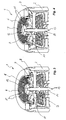
- ein selbstreinigendes und in das Auslaufmundstück einer sanitären Auslaufarmatur einsetzbares Einbauelement in einem perspektivischen Längsschnitt, wobei sich in dem Einbauelement eine als Strahlregler ausgestaltete Funktionseinheit befindet, die den Filteröffnungen eines Filtersiebes in Strömungsrichtung nachgeschaltet ist, und wobei das Filtersieb auch eine zentrale Auslassöffnung hat, die in einem By-Pass-Kanal mündet, der über ein hier in seiner Schließstellung befindliches Ventil ansteuerbar ist,
- Fig. 2
- das
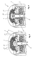
Einbauelement aus Figur 1 in der Offenstellung seines, den By-Pass-Kanal ansteuernden Ventils, - Fig. 3
ein mit Figur 1 und 2 vergleichbares Einbauelement in seiner Schließstellung, das ein Ventil mit einem über das Einbauelement vorstehenden Führungszapfen hat, wobei der vorstehende Endbereich des Führungszapfens als Handhabe zum manuellen Betätigen des Ventils ausgestaltet ist,- Fig. 4
- das
Einbauelement aus Figur 3 in der Offenstellung seines Ventils, - Fig. 5
- ein in der Schließstellung seines Ventils dargestelltes Einbauelement, dessen Ventil einen rohrförmigen Ventilkörper hat, wobei in dem Rohrinneren des rohrförmigen Ventilkörpers der By-Pass-Kanal vorgesehen ist,
- Fig. 6
- das
Einbauelement aus Figur 5 in der Offenstellung seines Ventils, - Fig. 7
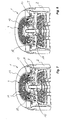
- ein in der Schließstellung seines Ventils dargestelltes Einbauelement, das in seinem Einbaugehäuse eine als Strahlregler ausgestaltete und eine als Durchflussmengenregler ausgebildete Funktionseinheit zusammenfasst,
- Fig. 8
- das
Einbauelement aus Figur 7 in der Offenstellung seines Ventils, - Fig. 9
- ein in der Schließstellung seines Ventils gezeigtes Einbauelement, wobei das Einbauelement einen Strahlregler als Funktionseinheit beinhaltet, welcher Strahlregler einen als Diffusor ausgestalteten Strahlzerleger hat,
- Fig. 10
- das Einbauelement aus
Figur 9 in der Offenstellung seines Ventils, - Fig. 11
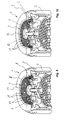
ein mit Figur 1 und 2 vergleichbar ausgestaltetes selbstreinigendes Einbauelement, dem hier ein Vorsatzsieb in Strömungsrichtung vorgeschaltet ist,- Fig. 12
- das
Einbauelement aus Figur 11 in der Offenstellung seines Ventils, - Fig. 13
- ein Einbauelement mit einem in seiner Schließstellung befindlichen Ventil, wobei der schirm- oder pilzförmige Ventilkörper des Ventils aus elastischem Material hergestellt und unter dem Staudruck des zuströmenden Wassers von seiner Offenstellung gegen die Rückstellkraft des elastischen Materials in eine Schließstellung des Ventils bewegbar ist,
- Fig. 14
- das
Einbauelement aus Figur 13 in der Offenstellung seines Ventils, - Fig. 15
- ein Einbauelement mit einem, in seiner Offenstellung befindlichen Ventil, welches Ventil einen ringförmig ausgebildeten und an einem Führungszapfen verschieblich geführten Ventilkörper hat, wobei an dem Ventilkörper ein kappenförmiges Rückstellelement aus elastischem Material angeformt ist, welches den freien Endbereich des Führungszapfens übergreift,
- Fig. 16
- das
Einbauelement aus Figur 15 in der Schließstellung seines Ventils, - Fig. 17
ein mit Figur 15 und 16 vergleichbar ausgebildetes Einbauelement mit einem, in seiner Offenstellung befindlichen Ventil, wobei das Ventil ein kappenförmiges Rückstellelement hat, dessen Kappenumfang federbalgartig ausgestaltet ist,- Fig. 18
- das
Einbauelement aus Figur 17 in der Schließstellung seines Ventils, - Fig. 19
- ein
mit den Figuren 15 vergleichbar ausgebildetes Einbauelement mit einem in seiner Offenstellung befindlichen Ventil, wobei das Ventil einem hülsenförmigen By-Pass-Kanal zuströmseitig vorgeschaltet ist, dessen Kanalauslass auf der Abströmseite des Einbauelements mündet,bis 18 - Fig. 20
- das Einbauelement aus
Figur 19 in der Schließstellung seines Ventils, - Fig. 21
- ein mit
Figur 19 und 20 vergleichbares Einbauelement mit einem in seiner Offenstellung befindlichen Ventil, dessen Ventilkörper mit einem kappenförmigen Rückstellelement verbunden ist, welches Rückstellelement as seinem Kappenumfang als Federbalg ausgestaltet ist, - Fig. 22
- das
Einbauelement aus Figur 21 in der Schließstellung seines Ventils, - Fig. 23
ein mit Figur 17 und 18 vergleichbares Einbauelement, wobei das als Strahlregler ausgebildete Einbauelement hier einen als Diffusor ausgestalteten Strahlzerleger hat,- Fig. 24
- das Einbauelement aus
Figur 23 in der Schließstellung seines Ventils, - Fig. 25
ein mit Figur 15 und 16 vergleichbares und in der Offenstellung seines Ventils abgebildetes Einbauelement, das hier ebenfalls einen Diffusor als Strahlzerleger ausweist,- Fig. 26
- das Einbauelement aus
Figur 25 in der Schließstellung seines Ventils und - Fig. 27
- die Durchflusskurve der in
den Figuren 1 bis 26 gezeigten und als Strahlregler ausgebildeten Einbauelemente (durchgezogene Linie) im Vergleich zur Durchflusskurve eines herkömmlichen und gemäß dem Stand der Technik ausgestalteten Strahlreglers (strichpunktierte Linie).
- Fig. 1
- a self-cleaning and insertable into the outlet mouthpiece of a sanitary outlet fitting installation element in a perspective longitudinal section, wherein in the installation element designed as a jet regulator functional unit is downstream of the filter openings of a filter screen in the flow direction, and wherein the filter screen also has a central outlet opening in a By-pass channel opens, which is controllable via a valve located here in its closed position,
- Fig. 2
- the built-in element
FIG. 1 in the open position of its valve, which actuates the by-pass channel, - Fig. 3
- one with
FIGS. 1 and 2 comparable installation element in its closed position, which has a valve with a guide pin projecting above the installation element, the projecting end area of the guide pin being configured as a handle for manual actuation of the valve, - Fig. 4
- the built-in element
FIG. 3 in the open position of its valve, - Fig. 5
- a built-in element in the closed position of its valve, the valve of which has a tubular valve body, wherein in the tube interior of the tubular valve body, the by-pass channel is provided,
- Fig. 6
- the built-in element
FIG. 5 in the open position of its valve, - Fig. 7
- a in the closed position of its valve shown installation element which summarizes in its housing a built-in as a jet regulator and designed as a flow rate controller functional unit,
- Fig. 8
- the built-in element
FIG. 7 in the open position of its valve, - Fig. 9
- an installation element shown in the closed position of its valve, wherein the installation element includes a jet regulator as a functional unit, which jet regulator has a jet splitter configured as a diffuser,
- Fig. 10
- the built-in element
FIG. 9 in the open position of its valve, - Fig. 11
- one with
FIGS. 1 and 2 comparable ausgestaltetes self-cleaning mounting element, which is preceded by a front screen in the flow direction, - Fig. 12
- the built-in element
FIG. 11 in the open position of its valve, - Fig. 13
- a built-in element with a valve located in its closed position, wherein the umbrella or mushroom-shaped valve body of the valve made of elastic material and is movable under the back pressure of the incoming water from its open position against the restoring force of the elastic material in a closed position of the valve,
- Fig. 14
- the built-in element
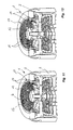
FIG. 13 in the open position his valve, - Fig. 15
- a built-in element with a valve in its open position, which valve has a ring-shaped valve body slidably guided on a guide pin, wherein on the valve body, a cap-shaped restoring element made of elastic material is formed, which engages over the free end portion of the guide pin,
- Fig. 16
- the built-in element
FIG. 15 in the closed position of its valve, - Fig. 17
- one with
FIGS. 15 and 16 Comparable trained installation element with a, located in its open position valve, wherein the valve has a cap-shaped return element, the cap circumference is designed spring bellows, - Fig. 18
- the built-in element
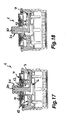
FIG. 17 in the closed position of its valve, - Fig. 19
- one with the
FIGS. 15 to 18 Comparable trained installation element with a valve located in its open position, wherein the valve is connected upstream of a sleeve-shaped by-pass channel on the inlet side, the channel outlet opens on the downstream side of the installation element, - Fig. 20
- the built-in element
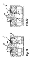
FIG. 19 in the closed position of its valve, - Fig. 21
- one with
FIGS. 19 and 20 comparable installation element with a in its open position located valve whose valve body is connected to a cap-shaped restoring element, which restoring element is designed as its cap circumference as bellows, - Fig. 22
- the built-in element
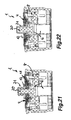
FIG. 21 in the closed position of its valve, - Fig. 23
- one with
FIGS. 17 and 18 comparable installation element, wherein the built-in as a jet regulator mounting element here has a designed as a diffuser jet splitter, - Fig. 24
- the built-in element
FIG. 23 in the closed position of its valve, - Fig. 25
- one with
FIGS. 15 and 16 comparable and in the open position of its valve mapped installation element, which also identifies here a diffuser as a jet separator, - Fig. 26
- the built-in element
FIG. 25 in the closed position of its valve and - Fig. 27
- the flow curve in the
FIGS. 1 to 26 built and designed as a jet regulator built-in elements (solid line) compared to the flow curve of a conventional and designed according to the prior art jet regulator (dash-dotted line).
In den
Die in den
Wie beispielsweise aus einem Vergleich der
Dabei weisen die der zumindest einen Funktionseinheit 3 vorgeschalteten Filteröffnungen 11 des Filtersiebs 4 einen im Vergleich zu den Durchtrittsöffnungen 10 des zumindest einen flüssigkeitsführenden Bestandteils 7, 8 allenfalls gleich großen und vorzugsweise kleineren lichten Durchflussquerschnitt auf, so dass solche Schmutzpartikel, welche die Filteröffnungen des Filtersiebes 4 passiert haben, auf jeden Fall auch durch die Durchtrittöffnungen oder Durchtrittslöcher 10 des flüssigkeitsführenden Bestandteils 7, 8 passen.In this case, the at least one
Bei den in
Aus den
Während der Ventilkörper 12 der in den
In den
Aus einem Vergleich der
In den
Aus den
Es versteht sich, dass die in den
Wie aus einem Vergleich der
Das aus elastischem Material hergestellte Rückstellelement 21 ist kappenförmig ausgebildet. Das kappenförmige Rückstellelemente 21 übergreift den Führungszapfen 20 und ist mit seinem abströmseitigen Umfangsrandbereich derart einstückig an den Ventilkörper 12 angeformt, dass das Rückstellelement 21 an gegenüberliegenden Stirnrändern mit dem ventilkörper 12 verbunden ist, während es sich mit seinem Mittelbereich auf der zuströmseitigen Stirnseite des Führungszapfens 20 abstützt.The restoring
Während das Rückstellelement 21 der in den
Der By-Pass-Kanal der in den
Dabei ist der Strahlzerleger der in den
Claims (26)
- Sanitary insert element (1) having at least one bypass duct (6) which is assigned a valve, in the open position of which the at least one bypass duct (6) is activated, wherein the duct outlet of the at least one bypass duct (6) is arranged downstream, as viewed in a flow direction, of at least one liquid-conducting component (7, 8) of at least one functional unit situated in the insert element, characterized in that the insert element (1) has a filter screen (4) with at least one outlet opening (5), which outlet opening (5) has a clear opening cross section which is enlarged in relation to the filter openings (11) of the filter screen (4), in that the at least one outlet opening (5) issues into the at least one bypass duct (6), and in that the outlet opening (5) is arranged upstream, as viewed in the flow direction, of the at least one liquid-conducting component (7, 8) of the at least one functional unit situated in the insert element.
- Insert element according to Claim 1, characterized in that the at least one valve can be moved from its open position into its closed position under the dynamic pressure of the inflowing water.
- Insert element according to Claim 1 or 2, characterized in that the insert element (1) is of self-cleaning design and in that, for this purpose, the at least one valve can be moved into its closed position under the dynamic pressure of the inflowing water counter to a restoring force.
- Insert element according to one of Claims 1 to 3, characterized in that the insert element (1) has a jet regulator (3) as functional unit, and in that a jet splitter is provided as at least one of the liquid-conducting components.
- Insert element according to Claim 4, characterized in that the jet splitter is in the form of a perforated plate (7) or a diffuser (8).
- Insert element according to one of Claims 1 to 5, characterized in that at least some of the filter openings (11) of the filter screen (4) have a clear throughflow cross section which is of the same size as or smaller than the passage openings of the at least one liquid-conducting component (7, 8) .
- Insert element according to one of Claims 1 to 6, characterized in that the at least one functional unit (3, 4) is positioned downstream, as viewed in the flow direction, of the filter openings (11) of the filter screen (4).
- Insert element according to one of Claims 1 to 7, characterized in that the at least one valve has a valve body (12) which is guided displaceably in the insert element (1) counter to a restoring force.
- Insert element according to Claim 8, characterized in that a sub-region, which is guided through the insert element (1), of the valve body (12) projects at least as far as the water outlet of the insert element (1) and is designed as a handle (15) for the manual actuation of the valve.
- Insert element according to Claim 8 or 9, characterized in that the valve body (12) is of mushroom-shaped or plate-shaped form.
- Insert element according to one of Claims 8 to 10, characterized in that the valve body (12) has a guide peg (14) guided displaceably in the insert element (1).
- Insert element according to Claim 11, characterized in that the guide peg (14) is of tubular form, in that the tube interior of the guide peg (14) is in the form of a bypass duct (6), and in that at least one liquid inlet is provided in the inflow-side end region of the guide peg (14) and at least one liquid outlet is provided in the outflow-side end region of the guide peg (14).
- Insert element according to Claim 12, characterized in that the outflow-side face opening, which projects preferably at least as far as the water outlet of the insert element (1), of the guide peg (14) is in the form of a liquid outlet.
- Insert element according to one of Claims 11 to 13, characterized in that the outflow-side end region of the guide peg (14) is of crown-shaped form.
- Insert element according to Claim 8, characterized in that the valve body (12), at least in an umbrella-shaped sub-region, is of elastic form and has an encircling sealing lip on the outer circumference, and in that the umbrella-shaped sub-region can be moved from an open position into a closed position counter to the elasticity of the elastic material.
- Insert element according to one of Claims 1 to 15, characterized in that the edge region, which borders the outlet opening (5), of the filter screen (4) is in the form of a valve seat that interacts with the valve body (12).
- Insert element according to one of Claims 1 to 16, characterized in that at least one upstream screen (17) is positioned upstream, as viewed in the flow direction, of the insert element (1).
- Insert element according to one of Claims 3 to 17, characterized in that the insert element (1) has the jet regulator (3) and a throughflow rate regulator (18), which is preferably positioned upstream, as functional units.
- Insert element according to one of Claims 1 to 18, characterized in that the filter screen (4) is of funnel-shaped form, and in that the funnel opening of the filter screen (4) serves as outlet opening (5).
- Insert element according to one of Claims 17 to 19, characterized in that the funnel-shaped filter screen (4) has a substantially convex or concave funnel shape.
- Insert element according to one of Claims 18 to 20, characterized in that the valve body (12) is guided displaceably on a guide peg (20) that projects beyond the filter screen (4), and in that at least one restoring element (21) composed of elastic material is provided, which restoring element is connected at one side to the valve body (12) and at the other side to the guide peg (20).
- Insert element according to Claim 21, characterized in that the valve body (12) engages annularly around the guide peg (20).
- Insert element according to Claim 21 or 22, characterized in that the restoring element (21) is, by way of opposite face edges, formed integrally on the valve body (12), and in that the restoring element (21) is supported by way of its central region on the inflow-side face side of the guide peg (20).
- Insert element according to one of Claims 21 to 23, characterized in that the restoring element (21) engages over the guide peg (20) in the manner of a cap, and in that the restoring element (21) is, by way of its outflow-side circumferential edge region, formed integrally on the valve body (12).
- Insert element according to Claim 24, characterized in that the valve body (12) is guided displaceably on the guide peg (20) substantially by the elastically flexible cap circumference of the restoring element (21).
- Insert element according to Claim 24 or 25, characterized in that the restoring element (21) has a cap circumference in the form of a spring bellows.
Priority Applications (1)
| Application Number | Priority Date | Filing Date | Title |
|---|---|---|---|
| PL07856279T PL2097589T3 (en) | 2006-12-06 | 2007-11-28 | Sanitory installation element |
Applications Claiming Priority (2)
| Application Number | Priority Date | Filing Date | Title |
|---|---|---|---|
| DE102006057795A DE102006057795B3 (en) | 2006-12-06 | 2006-12-06 | Sanitary installation unit for use as aerator, has filter sieve with dirt outlet opening, which has increased opening cross-section compared to sieve openings of filter sieve, where dirt outlet opening ends into bypass or cleaning channel |
| PCT/EP2007/010314 WO2008067936A1 (en) | 2006-12-06 | 2007-11-28 | Sanitory installation element |
Publications (2)
| Publication Number | Publication Date |
|---|---|
| EP2097589A1 EP2097589A1 (en) | 2009-09-09 |
| EP2097589B1 true EP2097589B1 (en) | 2014-10-08 |
Family
ID=38955160
Family Applications (1)
| Application Number | Title | Priority Date | Filing Date |
|---|---|---|---|
| EP07856279.0A Active EP2097589B1 (en) | 2006-12-06 | 2007-11-28 | Sanitory installation element |
Country Status (14)
| Country | Link |
|---|---|
| US (1) | US8308079B2 (en) |
| EP (1) | EP2097589B1 (en) |
| JP (1) | JP5361732B2 (en) |
| KR (2) | KR101516022B1 (en) |
| CN (1) | CN101395323B (en) |
| AU (1) | AU2007327986B2 (en) |
| BR (1) | BRPI0707667A8 (en) |
| DE (2) | DE102006057795B3 (en) |
| ES (1) | ES2523319T3 (en) |
| IL (1) | IL193537A (en) |
| MX (1) | MX2008010848A (en) |
| PL (1) | PL2097589T3 (en) |
| RU (1) | RU2442860C2 (en) |
| WO (1) | WO2008067936A1 (en) |
Cited By (1)
| Publication number | Priority date | Publication date | Assignee | Title |
|---|---|---|---|---|
| CN104913094A (en) * | 2014-03-12 | 2015-09-16 | 厦门松霖科技有限公司 | Water saving device |
Families Citing this family (32)
| Publication number | Priority date | Publication date | Assignee | Title |
|---|---|---|---|---|
| ES2740150T3 (en) | 2006-12-06 | 2020-02-05 | Neoperl Gmbh | Sanitary Installation Element |
| US9481986B2 (en) * | 2006-12-06 | 2016-11-01 | Neoperl Gmbh | Sanitary installation element |
| WO2011047134A1 (en) * | 2009-10-15 | 2011-04-21 | Niagara Conservation Corp. | Aeration device |
| DE102010012326B4 (en) * | 2010-03-23 | 2015-10-01 | Neoperl Gmbh | aerator |
| DE102010055459A1 (en) * | 2010-05-27 | 2011-12-01 | Neoperl Gmbh | Sanitary outlet insert |
| CN102359154B (en) * | 2011-08-04 | 2013-03-27 | 厦门松霖科技有限公司 | Gas-water mixing bubbler |
| DE202011105376U1 (en) * | 2011-09-06 | 2012-12-10 | Neoperl Gmbh | Sanitary installation part |
| CN103132565A (en) * | 2011-11-28 | 2013-06-05 | 纽珀有限公司 | Hygienic insertion unit |
| DE102012021361B4 (en) * | 2012-11-02 | 2014-11-06 | Neoperl Gmbh | aerator |
| DE202012010420U1 (en) * | 2012-11-02 | 2014-02-03 | Neoperl Gmbh | aerator |
| DE202013000860U1 (en) * | 2013-01-29 | 2014-05-05 | Neoperl Gmbh | Sanitary installation part and component of a sanitary fitting |
| CN103821201B (en) * | 2014-03-21 | 2016-08-17 | 厦门松霖科技有限公司 | Discharging device with cleaning function |
| DE102014005854B4 (en) * | 2014-04-22 | 2022-11-17 | Neoperl Gmbh | pressure reducing valve |
| CN105588124A (en) * | 2014-10-28 | 2016-05-18 | 中国航空工业集团公司西安飞机设计研究所 | Multi-profile oil-spraying fire generator |
| DE102015017107A1 (en) * | 2015-03-09 | 2016-09-15 | Neoperl Gmbh | Sanitary insert unit |
| DE202015001754U1 (en) * | 2015-03-09 | 2016-06-10 | Neoperl Gmbh | Flow regulator unit |
| DE202015001886U1 (en) * | 2015-03-09 | 2016-06-10 | Neoperl Gmbh | Sanitary insert unit |
| CN106031902B (en) * | 2015-03-17 | 2020-03-17 | 厦门松霖科技股份有限公司 | Shower head with impurity discharge flow channel |
| DE202016001630U1 (en) * | 2016-03-14 | 2017-06-16 | Neoperl Gmbh | aerator |
| US11248368B2 (en) | 2016-04-14 | 2022-02-15 | Delta Faucet Company | Faucet aerator with center stream |
| DE102016006498B4 (en) * | 2016-05-28 | 2018-02-15 | Neoperl Gmbh | Sanitary insert unit |
| DE202016003402U1 (en) | 2016-05-28 | 2017-08-30 | Neoperl Gmbh | Sanitary insert unit |
| DE202016005553U1 (en) * | 2016-09-08 | 2017-12-11 | Neoperl Gmbh | Sanitary insert unit |
| DE102016011168A1 (en) | 2016-09-16 | 2018-03-22 | Neoperl Gmbh | Sanitary unit |
| US10358803B2 (en) * | 2016-09-30 | 2019-07-23 | Toto Ltd. | Spout apparatus |
| USD964514S1 (en) | 2017-03-07 | 2022-09-20 | Neoperl Gmbh | Faucet stream straightener |
| DE102017214571B4 (en) * | 2017-08-21 | 2019-02-28 | Hansgrohe Se | Sanitary fitting with water channel |
| US11591780B2 (en) * | 2020-04-15 | 2023-02-28 | Yeuu Deng Sanitary Facilities Industrial Co., Ltd. | Faucet aerator |
| DE202020103566U1 (en) * | 2020-06-19 | 2021-09-23 | Neoperl Gmbh | Aerator |
| CN111827417A (en) * | 2020-07-07 | 2020-10-27 | 厦门水蜻蜓卫浴科技有限公司 | Water outlet device |
| DE102021127212A1 (en) * | 2021-10-20 | 2023-04-20 | Neoperl Gmbh | Sanitary functional unit |
| DE202022106621U1 (en) * | 2022-11-25 | 2023-11-29 | Neoperl Gmbh | Sanitary installation part |
Family Cites Families (16)
| Publication number | Priority date | Publication date | Assignee | Title |
|---|---|---|---|---|
| US3104819A (en) * | 1963-09-24 | Spiral screened fluid mixing devices | ||
| US2014063A (en) * | 1934-06-06 | 1935-09-10 | John S Brady | Self-cleaning faucet filter |
| DE2658742C2 (en) * | 1976-12-24 | 1985-08-01 | Dieter Wildfang KG, 7840 Müllheim | Aerator |
| US4313564A (en) * | 1979-01-17 | 1982-02-02 | Shames Sidney J | Self-cleaning aerator with noise reduction |
| US4214702A (en) * | 1979-01-17 | 1980-07-29 | Shames | Self-cleaning aerator |
| SU1000523A1 (en) * | 1981-04-29 | 1983-02-28 | Производственное Объединение "Ростовсантехника" Им.И.Д.Ченцова | Aerator |
| US4562960A (en) * | 1983-03-14 | 1986-01-07 | Masco Corporation Of Indiana | Pressure responsive aerator |
| DE3642356C2 (en) | 1986-12-11 | 1995-10-05 | Wildfang Dieter Gmbh | Aerator |
| WO1998016693A1 (en) * | 1996-10-11 | 1998-04-23 | Dieter Wildfang Gmbh | Sanitary outlet |
| DE29822353U1 (en) * | 1998-01-08 | 1999-05-12 | INGWA Umwelttechnik GmbH, 28832 Achim | Device for reducing the flow rate of liquids |
| US6241880B1 (en) * | 1999-09-13 | 2001-06-05 | James Yahr | Self-cleaning faucet filter |
| DE10027987B4 (en) * | 2000-06-06 | 2005-12-22 | Neoperl Gmbh | aerator |
| DE102005010551B4 (en) * | 2005-03-04 | 2007-05-16 | Neoperl Gmbh | Sanitary functional unit |
| JP4501499B2 (en) | 2004-03-31 | 2010-07-14 | Toto株式会社 | Water discharge switching device |
| DE102004044158B3 (en) * | 2004-09-13 | 2006-01-12 | Hansa Metallwerke Ag | Water outlet mouthpiece with a switchable jet regulator insert |
| AU2005331853B2 (en) * | 2005-05-18 | 2011-09-01 | Neoperl Gmbh | Sanitary component, namely jet regulator or jet former for flowing, fluid media, method of producing such a sanitary component and use of a sanitary component |
-
2006
- 2006-12-06 DE DE102006057795A patent/DE102006057795B3/en not_active Expired - Fee Related
-
2007
- 2007-03-02 DE DE202007003264U patent/DE202007003264U1/en not_active Expired - Lifetime
- 2007-11-28 EP EP07856279.0A patent/EP2097589B1/en active Active
- 2007-11-28 CN CN2007800078396A patent/CN101395323B/en active Active
- 2007-11-28 KR KR1020087024400A patent/KR101516022B1/en not_active IP Right Cessation
- 2007-11-28 KR KR1020147036525A patent/KR20150013909A/en not_active Application Discontinuation
- 2007-11-28 PL PL07856279T patent/PL2097589T3/en unknown
- 2007-11-28 JP JP2009539640A patent/JP5361732B2/en not_active Expired - Fee Related
- 2007-11-28 MX MX2008010848A patent/MX2008010848A/en active IP Right Grant
- 2007-11-28 WO PCT/EP2007/010314 patent/WO2008067936A1/en active Application Filing
- 2007-11-28 RU RU2008132731/13A patent/RU2442860C2/en not_active IP Right Cessation
- 2007-11-28 ES ES07856279.0T patent/ES2523319T3/en active Active
- 2007-11-28 AU AU2007327986A patent/AU2007327986B2/en not_active Ceased
- 2007-11-28 BR BRPI0707667A patent/BRPI0707667A8/en not_active IP Right Cessation
- 2007-11-28 US US12/296,531 patent/US8308079B2/en active Active
-
2008
- 2008-08-19 IL IL193537A patent/IL193537A/en active IP Right Grant
Cited By (2)
| Publication number | Priority date | Publication date | Assignee | Title |
|---|---|---|---|---|
| CN104913094A (en) * | 2014-03-12 | 2015-09-16 | 厦门松霖科技有限公司 | Water saving device |
| CN104913094B (en) * | 2014-03-12 | 2017-05-10 | 厦门松霖科技有限公司 | Water saving device |
Also Published As
| Publication number | Publication date |
|---|---|
| BRPI0707667A2 (en) | 2011-05-10 |
| KR101516022B1 (en) | 2015-05-04 |
| US20090224067A1 (en) | 2009-09-10 |
| EP2097589A1 (en) | 2009-09-09 |
| MX2008010848A (en) | 2008-09-05 |
| KR20090093791A (en) | 2009-09-02 |
| AU2007327986A1 (en) | 2008-06-12 |
| IL193537A (en) | 2013-08-29 |
| DE102006057795B3 (en) | 2008-02-21 |
| JP5361732B2 (en) | 2013-12-04 |
| KR20150013909A (en) | 2015-02-05 |
| JP2010511497A (en) | 2010-04-15 |
| RU2442860C2 (en) | 2012-02-20 |
| US8308079B2 (en) | 2012-11-13 |
| CN101395323A (en) | 2009-03-25 |
| WO2008067936A1 (en) | 2008-06-12 |
| DE202007003264U1 (en) | 2008-04-17 |
| IL193537A0 (en) | 2009-02-11 |
| BRPI0707667A8 (en) | 2018-04-24 |
| CN101395323B (en) | 2011-11-02 |
| ES2523319T3 (en) | 2014-11-24 |
| RU2008132731A (en) | 2010-04-27 |
| PL2097589T3 (en) | 2015-03-31 |
| AU2007327986B2 (en) | 2013-10-03 |
| BRPI0707667B1 (en) | 2017-11-21 |
Similar Documents
| Publication | Publication Date | Title |
|---|---|---|
| EP2097589B1 (en) | Sanitory installation element | |
| EP2100200B1 (en) | Flow rate regulator | |
| EP2576925B1 (en) | Sanitary outlet insert | |
| DE202006018577U1 (en) | Sanitary installation element | |
| EP3510204B1 (en) | Sanitary insert unit | |
| EP3199714B1 (en) | Sanitary outlet unit | |
| WO2008067948A1 (en) | Sanitary installation element | |
| DE102007009717A1 (en) | Tap has outlet fitted with perforated plate, filter sieve being mounted above plate, outlets for material removed by it connecting with cleaning channels which discharge downstream from perforated plate | |
| DE202007002904U1 (en) | Flow regulator | |
| DE102007010618B4 (en) | Sanitary installation element | |
| WO2016142060A2 (en) | Sanitary change-over valve and assembly comprising a change-over valve of this type | |
| DE102016015807B4 (en) | Sanitary insert unit | |
| DE102016010842B4 (en) | Sanitary insert unit | |
| DE202005001101U1 (en) | One-piece transparent plastic filter sieve plug for water tap spout outlet has an array of sieve holes | |
| EP3327208B1 (en) | Sanitary outlet unit | |
| DE102015001383B4 (en) | Sanitary outlet element | |
| DE102005003276B4 (en) | Sanitary functional unit for a water outlet fitting | |
| AU2013231013B2 (en) | Sanitory installation element | |
| DE102015001371B3 (en) | Sanitary insert unit | |
| DE102015017072B4 (en) | Sanitary insert unit |
Legal Events
| Date | Code | Title | Description |
|---|---|---|---|
| PUAI | Public reference made under article 153(3) epc to a published international application that has entered the european phase |
Free format text: ORIGINAL CODE: 0009012 |
|
| 17P | Request for examination filed |
Effective date: 20080514 |
|
| AK | Designated contracting states |
Kind code of ref document: A1 Designated state(s): AT BE BG CH CY CZ DE DK EE ES FI FR GB GR HU IE IS IT LI LT LU LV MC MT NL PL PT RO SE SI SK TR |
|
| AX | Request for extension of the european patent |
Extension state: AL BA HR MK RS |
|
| DAX | Request for extension of the european patent (deleted) | ||
| 17Q | First examination report despatched |
Effective date: 20101201 |
|
| GRAP | Despatch of communication of intention to grant a patent |
Free format text: ORIGINAL CODE: EPIDOSNIGR1 |
|
| INTG | Intention to grant announced |
Effective date: 20140630 |
|
| GRAS | Grant fee paid |
Free format text: ORIGINAL CODE: EPIDOSNIGR3 |
|
| GRAA | (expected) grant |
Free format text: ORIGINAL CODE: 0009210 |
|
| AK | Designated contracting states |
Kind code of ref document: B1 Designated state(s): AT BE BG CH CY CZ DE DK EE ES FI FR GB GR HU IE IS IT LI LT LU LV MC MT NL PL PT RO SE SI SK TR |
|
| REG | Reference to a national code |
Ref country code: GB Ref legal event code: FG4D Free format text: NOT ENGLISH |
|
| REG | Reference to a national code |
Ref country code: AT Ref legal event code: REF Ref document number: 690720 Country of ref document: AT Kind code of ref document: T Effective date: 20141015 Ref country code: CH Ref legal event code: EP |
|
| REG | Reference to a national code |
Ref country code: IE Ref legal event code: FG4D Free format text: LANGUAGE OF EP DOCUMENT: GERMAN |
|
| REG | Reference to a national code |
Ref country code: DE Ref legal event code: R096 Ref document number: 502007013511 Country of ref document: DE Effective date: 20141113 |
|
| REG | Reference to a national code |
Ref country code: CH Ref legal event code: NV Representative=s name: HANS RUDOLF GACHNANG PATENTANWALT, CH |
|
| REG | Reference to a national code |
Ref country code: ES Ref legal event code: FG2A Ref document number: 2523319 Country of ref document: ES Kind code of ref document: T3 Effective date: 20141124 |
|
| REG | Reference to a national code |
Ref country code: DE Ref legal event code: R083 Ref document number: 502007013511 Country of ref document: DE |
|
| REG | Reference to a national code |
Ref country code: SE Ref legal event code: TRGR |
|
| REG | Reference to a national code |
Ref country code: NL Ref legal event code: T3 |
|
| REG | Reference to a national code |
Ref country code: LT Ref legal event code: MG4D |
|
| REG | Reference to a national code |
Ref country code: PL Ref legal event code: T3 |
|
| PG25 | Lapsed in a contracting state [announced via postgrant information from national office to epo] |
Ref country code: IS Free format text: LAPSE BECAUSE OF FAILURE TO SUBMIT A TRANSLATION OF THE DESCRIPTION OR TO PAY THE FEE WITHIN THE PRESCRIBED TIME-LIMIT Effective date: 20150208 Ref country code: FI Free format text: LAPSE BECAUSE OF FAILURE TO SUBMIT A TRANSLATION OF THE DESCRIPTION OR TO PAY THE FEE WITHIN THE PRESCRIBED TIME-LIMIT Effective date: 20141008 Ref country code: LT Free format text: LAPSE BECAUSE OF FAILURE TO SUBMIT A TRANSLATION OF THE DESCRIPTION OR TO PAY THE FEE WITHIN THE PRESCRIBED TIME-LIMIT Effective date: 20141008 Ref country code: PT Free format text: LAPSE BECAUSE OF FAILURE TO SUBMIT A TRANSLATION OF THE DESCRIPTION OR TO PAY THE FEE WITHIN THE PRESCRIBED TIME-LIMIT Effective date: 20150209 |
|
| PG25 | Lapsed in a contracting state [announced via postgrant information from national office to epo] |
Ref country code: CY Free format text: LAPSE BECAUSE OF FAILURE TO SUBMIT A TRANSLATION OF THE DESCRIPTION OR TO PAY THE FEE WITHIN THE PRESCRIBED TIME-LIMIT Effective date: 20141008 Ref country code: GR Free format text: LAPSE BECAUSE OF FAILURE TO SUBMIT A TRANSLATION OF THE DESCRIPTION OR TO PAY THE FEE WITHIN THE PRESCRIBED TIME-LIMIT Effective date: 20150109 Ref country code: LV Free format text: LAPSE BECAUSE OF FAILURE TO SUBMIT A TRANSLATION OF THE DESCRIPTION OR TO PAY THE FEE WITHIN THE PRESCRIBED TIME-LIMIT Effective date: 20141008 |
|
| PG25 | Lapsed in a contracting state [announced via postgrant information from national office to epo] |
Ref country code: BE Free format text: LAPSE BECAUSE OF NON-PAYMENT OF DUE FEES Effective date: 20141130 |
|
| REG | Reference to a national code |
Ref country code: DE Ref legal event code: R097 Ref document number: 502007013511 Country of ref document: DE |
|
| PG25 | Lapsed in a contracting state [announced via postgrant information from national office to epo] |
Ref country code: CZ Free format text: LAPSE BECAUSE OF FAILURE TO SUBMIT A TRANSLATION OF THE DESCRIPTION OR TO PAY THE FEE WITHIN THE PRESCRIBED TIME-LIMIT Effective date: 20141008 Ref country code: MC Free format text: LAPSE BECAUSE OF FAILURE TO SUBMIT A TRANSLATION OF THE DESCRIPTION OR TO PAY THE FEE WITHIN THE PRESCRIBED TIME-LIMIT Effective date: 20141008 Ref country code: EE Free format text: LAPSE BECAUSE OF FAILURE TO SUBMIT A TRANSLATION OF THE DESCRIPTION OR TO PAY THE FEE WITHIN THE PRESCRIBED TIME-LIMIT Effective date: 20141008 Ref country code: RO Free format text: LAPSE BECAUSE OF FAILURE TO SUBMIT A TRANSLATION OF THE DESCRIPTION OR TO PAY THE FEE WITHIN THE PRESCRIBED TIME-LIMIT Effective date: 20141008 Ref country code: DK Free format text: LAPSE BECAUSE OF FAILURE TO SUBMIT A TRANSLATION OF THE DESCRIPTION OR TO PAY THE FEE WITHIN THE PRESCRIBED TIME-LIMIT Effective date: 20141008 Ref country code: SK Free format text: LAPSE BECAUSE OF FAILURE TO SUBMIT A TRANSLATION OF THE DESCRIPTION OR TO PAY THE FEE WITHIN THE PRESCRIBED TIME-LIMIT Effective date: 20141008 |
|
| PLBE | No opposition filed within time limit |
Free format text: ORIGINAL CODE: 0009261 |
|
| STAA | Information on the status of an ep patent application or granted ep patent |
Free format text: STATUS: NO OPPOSITION FILED WITHIN TIME LIMIT |
|
| REG | Reference to a national code |
Ref country code: IE Ref legal event code: MM4A |
|
| 26N | No opposition filed |
Effective date: 20150709 |
|
| PG25 | Lapsed in a contracting state [announced via postgrant information from national office to epo] |
Ref country code: IE Free format text: LAPSE BECAUSE OF NON-PAYMENT OF DUE FEES Effective date: 20141128 |
|
| REG | Reference to a national code |
Ref country code: FR Ref legal event code: PLFP Year of fee payment: 9 |
|
| PG25 | Lapsed in a contracting state [announced via postgrant information from national office to epo] |
Ref country code: SI Free format text: LAPSE BECAUSE OF FAILURE TO SUBMIT A TRANSLATION OF THE DESCRIPTION OR TO PAY THE FEE WITHIN THE PRESCRIBED TIME-LIMIT Effective date: 20141008 |
|
| PG25 | Lapsed in a contracting state [announced via postgrant information from national office to epo] |
Ref country code: BG Free format text: LAPSE BECAUSE OF FAILURE TO SUBMIT A TRANSLATION OF THE DESCRIPTION OR TO PAY THE FEE WITHIN THE PRESCRIBED TIME-LIMIT Effective date: 20141008 |
|
| PG25 | Lapsed in a contracting state [announced via postgrant information from national office to epo] |
Ref country code: HU Free format text: LAPSE BECAUSE OF FAILURE TO SUBMIT A TRANSLATION OF THE DESCRIPTION OR TO PAY THE FEE WITHIN THE PRESCRIBED TIME-LIMIT; INVALID AB INITIO Effective date: 20071128 Ref country code: MT Free format text: LAPSE BECAUSE OF FAILURE TO SUBMIT A TRANSLATION OF THE DESCRIPTION OR TO PAY THE FEE WITHIN THE PRESCRIBED TIME-LIMIT Effective date: 20141008 Ref country code: LU Free format text: LAPSE BECAUSE OF NON-PAYMENT OF DUE FEES Effective date: 20141128 |
|
| REG | Reference to a national code |
Ref country code: FR Ref legal event code: PLFP Year of fee payment: 10 |
|
| PGFP | Annual fee paid to national office [announced via postgrant information from national office to epo] |
Ref country code: GB Payment date: 20170908 Year of fee payment: 11 |
|
| REG | Reference to a national code |
Ref country code: FR Ref legal event code: PLFP Year of fee payment: 11 |
|
| PGFP | Annual fee paid to national office [announced via postgrant information from national office to epo] |
Ref country code: NL Payment date: 20171122 Year of fee payment: 11 |
|
| REG | Reference to a national code |
Ref country code: NL Ref legal event code: MM Effective date: 20181201 |
|
| GBPC | Gb: european patent ceased through non-payment of renewal fee |
Effective date: 20181128 |
|
| PG25 | Lapsed in a contracting state [announced via postgrant information from national office to epo] |
Ref country code: NL Free format text: LAPSE BECAUSE OF NON-PAYMENT OF DUE FEES Effective date: 20181201 |
|
| PG25 | Lapsed in a contracting state [announced via postgrant information from national office to epo] |
Ref country code: GB Free format text: LAPSE BECAUSE OF NON-PAYMENT OF DUE FEES Effective date: 20181128 |
|
| PGFP | Annual fee paid to national office [announced via postgrant information from national office to epo] |
Ref country code: ES Payment date: 20191216 Year of fee payment: 13 |
|
| REG | Reference to a national code |
Ref country code: ES Ref legal event code: FD2A Effective date: 20220207 |
|
| PG25 | Lapsed in a contracting state [announced via postgrant information from national office to epo] |
Ref country code: ES Free format text: LAPSE BECAUSE OF NON-PAYMENT OF DUE FEES Effective date: 20201129 |
|
| PGFP | Annual fee paid to national office [announced via postgrant information from national office to epo] |
Ref country code: SE Payment date: 20221122 Year of fee payment: 16 |
|
| PGFP | Annual fee paid to national office [announced via postgrant information from national office to epo] |
Ref country code: PL Payment date: 20221116 Year of fee payment: 16 |
|
| PGFP | Annual fee paid to national office [announced via postgrant information from national office to epo] |
Ref country code: TR Payment date: 20231121 Year of fee payment: 17 Ref country code: IT Payment date: 20231130 Year of fee payment: 17 Ref country code: FR Payment date: 20231124 Year of fee payment: 17 Ref country code: DE Payment date: 20231128 Year of fee payment: 17 Ref country code: CH Payment date: 20231201 Year of fee payment: 17 Ref country code: AT Payment date: 20231117 Year of fee payment: 17 |
|
| REG | Reference to a national code |
Ref country code: SE Ref legal event code: EUG |
|
| PG25 | Lapsed in a contracting state [announced via postgrant information from national office to epo] |
Ref country code: SE Free format text: LAPSE BECAUSE OF NON-PAYMENT OF DUE FEES Effective date: 20231129 |